EP2977099A1 - Membrane filter made of photosensitive material - Google Patents
Membrane filter made of photosensitive material Download PDFInfo
- Publication number
- EP2977099A1 EP2977099A1 EP15173691.5A EP15173691A EP2977099A1 EP 2977099 A1 EP2977099 A1 EP 2977099A1 EP 15173691 A EP15173691 A EP 15173691A EP 2977099 A1 EP2977099 A1 EP 2977099A1
- Authority
- EP
- European Patent Office
- Prior art keywords
- film
- thin film
- photosensitive composition
- substrate
- membrane filter
- Prior art date
- Legal status (The legal status is an assumption and is not a legal conclusion. Google has not performed a legal analysis and makes no representation as to the accuracy of the status listed.)
- Granted
Links
Images


Classifications
-
- B—PERFORMING OPERATIONS; TRANSPORTING
- B01—PHYSICAL OR CHEMICAL PROCESSES OR APPARATUS IN GENERAL
- B01D—SEPARATION
- B01D69/00—Semi-permeable membranes for separation processes or apparatus characterised by their form, structure or properties; Manufacturing processes specially adapted therefor
- B01D69/10—Supported membranes; Membrane supports
-
- B—PERFORMING OPERATIONS; TRANSPORTING
- B01—PHYSICAL OR CHEMICAL PROCESSES OR APPARATUS IN GENERAL
- B01D—SEPARATION
- B01D65/00—Accessories or auxiliary operations, in general, for separation processes or apparatus using semi-permeable membranes
- B01D65/003—Membrane bonding or sealing
-
- B—PERFORMING OPERATIONS; TRANSPORTING
- B01—PHYSICAL OR CHEMICAL PROCESSES OR APPARATUS IN GENERAL
- B01D—SEPARATION
- B01D67/00—Processes specially adapted for manufacturing semi-permeable membranes for separation processes or apparatus
- B01D67/0002—Organic membrane manufacture
- B01D67/002—Organic membrane manufacture from melts
-
- B—PERFORMING OPERATIONS; TRANSPORTING
- B01—PHYSICAL OR CHEMICAL PROCESSES OR APPARATUS IN GENERAL
- B01D—SEPARATION
- B01D67/00—Processes specially adapted for manufacturing semi-permeable membranes for separation processes or apparatus
- B01D67/0002—Organic membrane manufacture
- B01D67/0023—Organic membrane manufacture by inducing porosity into non porous precursor membranes
- B01D67/0032—Organic membrane manufacture by inducing porosity into non porous precursor membranes by elimination of segments of the precursor, e.g. nucleation-track membranes, lithography or laser methods
- B01D67/0034—Organic membrane manufacture by inducing porosity into non porous precursor membranes by elimination of segments of the precursor, e.g. nucleation-track membranes, lithography or laser methods by micromachining techniques, e.g. using masking and etching steps, photolithography
-
- B—PERFORMING OPERATIONS; TRANSPORTING
- B01—PHYSICAL OR CHEMICAL PROCESSES OR APPARATUS IN GENERAL
- B01D—SEPARATION
- B01D71/00—Semi-permeable membranes for separation processes or apparatus characterised by the material; Manufacturing processes specially adapted therefor
- B01D71/06—Organic material
- B01D71/46—Epoxy resins
-
- B—PERFORMING OPERATIONS; TRANSPORTING
- B01—PHYSICAL OR CHEMICAL PROCESSES OR APPARATUS IN GENERAL
- B01D—SEPARATION
- B01D2325/00—Details relating to properties of membranes
- B01D2325/24—Mechanical properties, e.g. strength
Definitions
- a preferred method when a thin film 14 has not through holes includes a method in which a thin film 14 is formed on a substrate 10 and a thick film of a photosensitive composition (hereinafter also referred to as the photosensitive composition thick film 15) is formed on the thin film 14, and then the thus formed photosensitive composition thick film 15 is exposed and developed to form a support film 19.
- This method is referred to as the first method of the preferred method for producing a membrane filter 21.
- alcohol-based solvent there is no particular limitation on the alcohol-based solvent, as long as it can dissolve a sacrificial film 11, and examples thereof include methanol, ethanol, and the like.
- a liquid negative photosensitive composition is applied on a surface of the sacrificial film 11 thus formed as mentioned above to form a photosensitive composition thin film 12.
- the method for applying a negative photosensitive composition on a surface of the sacrificial film 11 is the same as that in which a coating solution for formation of a sacrificial film is applied on a surface of a substrate 10.
- the thickness of the photosensitive composition thin film 12 is appropriately adjusted so as to form a thin film 14 having a thickness of 1 to 1,000 nm.
- a photosensitive composition thick film 15 is formed on the thin film 14.
- the photosensitive composition thick film 15 is preferably formed by applying a liquid photosensitive composition on the thin film 14.
- the method for applying a photosensitive composition on a surface of the thin film 14 is the same as that in which a coating solution for formation of a sacrificial film is applied on a surface of a substrate 10.
- the thickness of the photosensitive composition thick film 15 is appropriately adjusted so as to form a support film 19 having a thickness of 1 to 1,000 ⁇ m.
- a preferred method which is different from the first method when a thin film 14 has not through holes includes a method in which the thin film 14 formed on the substrate 10 is bonded to a surface of a support film 19 formed on the substrate 10 which is different from that including the thin film 14. This method is referred to as a second method of a preferred method for producing a membrane filter 21.
- the photosensitive composition thick film 15 is regioselectively exposed so as to completely expose the photosensitive composition filled in through holes of the thin film 14. Therefore, in the case of developing the exposed photosensitive composition thick film 15 with a developing solution 18, the photosensitive composition filled in through holes in the thin film 14 is dissolved in the developing solution 18, together with the exposed area 16 formed in the photosensitive composition thick film 15.
- Exposure was regioselectively performed through a mask so as to form circular holes each having a pore diameter of 10 ⁇ m at a pitch (a distance between centers of holes) of 50 ⁇ m.
- the substrate was immersed in PGMEA for 1 minute to thereby perform development to form a 10 ⁇ m thick support film including holes each having a circular opening with the above-mentioned diameter and pitch.
Landscapes
- Chemical & Material Sciences (AREA)
- Chemical Kinetics & Catalysis (AREA)
- Engineering & Computer Science (AREA)
- Manufacturing & Machinery (AREA)
- Physics & Mathematics (AREA)
- Optics & Photonics (AREA)
- Separation Using Semi-Permeable Membranes (AREA)
- Materials For Photolithography (AREA)
- Spectroscopy & Molecular Physics (AREA)
- General Physics & Mathematics (AREA)
Abstract




Description
- The present invention relates to a membrane filter in which a thin film having a nanometer order thickness and a support film which is a porous film having a micrometer order thickness are laminated with each other.
- In recent years, a self-supporting thin film having a large surface area and a nanometer order thickness attracts attention as a film which can be used as a selective permeable film, a film for microsensor and drug delivery, and the like. Therefore, various methods for producing a self-supporting thin film has been studied, and there have been known a water surface casting method, an interfacial reaction method using a silane coupling agent, and the like. However, thin films obtained by these methods usually have such problems that the thin films have insufficient mechanical strength and are not easy to achieve the enlargement of the area, and also there is limitation on accuracy of the obtained thin film.
-
Patent Document 1 discloses, an a specific example of a method for producing a self-supporting thin film, a polymer thin film having self-supportability even if the thickness is set at 100 nm or less, and a method for producing the polymer thin film. More specifically, the polymer thin film is produced by providing a sacrificial layer on a surface of a support, allowing a polymerizable compound in the composition to undergo chain polymerization on a surface of the sacrificial layer, and removing the sacrificial layer to thereby detach the support from the polymerized composition. - Patent Document 1: Japanese Unexamined Patent Application, Publication No.
2008-285617 - Certainly, the thin film produced by the method mentioned in
Patent Document 1 is an extremely thin film having a thickness of 100 nm or less, and has self-supportability. However, regardless of having self-supportability, such thin film is an ultrathin film having nanometer order thickness and is therefore fragile in view of strength, thus making it difficult for the thin film to use various applications. - Therefore, when the thin film produced in the method mentioned in
Patent Document 1 is applied to various applications, there is a need to compensate insufficient strength of the thin film by integrating some support film with the thin film. There is a need for such support film to support the thin film without a defect and also not to impair a functions such as selective permeability of the thin film. However, a sufficient study is not made on what kind of a support film can satisfactorily reinforce the thin film without impairing performances of the thin film, and also can easily form a laminate of a large area thin film with a support film. - The present invention has been made in light of the above problems, and an object thereof is to provide a membrane filter including a thin film having a nanometer order thickness as a base, which is easy to increase the size and also has enough strength for use as a filter.
- The present inventors have found that the above object can be achieved by laminating a thin film having a thickness of 1 to 1,000 nm, with a support film as a porous film having a thickness of 1 to 1,000 µm, which is made of a photosensitive composition or a cured product of the photosensitive composition, and has a plurality of hole portions penetrating in the thickness direction, leading to the production of a membrane filter. Thus, the present invention has been completed.
- A first aspect of the present invention is directed to a membrane filter comprising a thin film and a support film supporting the thin film, which are laminated with each other, wherein
the thin film has a thickness of 1 to 1,000 nm, and
the support film is a porous film having a thickness of 1 to 1,000 µm, which is made of a photosensitive composition or a cured product of the photosensitive composition, and has a plurality of hole portions penetrating in the thickness direction. - A second aspect of the present invention is directed to a method for producing a membrane filter comprising: laminating a thin film and a support film supporting the thin film, wherein
the thin film has a thickness of 1 to 1,000 nm, and
the support film is a porous film having a thickness of 1 to 1,000 µm that has a plurality of hole portions penetrating in the thickness direction, formed by exposure and development of a first photosensitive composition film. - According to the present invention, it is possible to provide a membrane filter including a thin film having a nanometer order thickness as a base, which is easy to increase the size and also has enough strength for use as a filter.
-
-
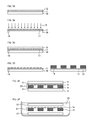
FIGs. 1A to 1H are view schematically showing a first method of a method for producing a membrane filter of the present invention. -
FIG. 1A is a view showing asubstrate 10 including asacrificial film 11. -
FIG. 1B is a view showing asubstrate 10 including asacrificial film 11 and a photosensitive compositionthin film 12. -
FIG. 1C is a view showing the formation of athin film 14 by irradiation ofexposure light 13 to a photosensitive compositionthin film 12 included in thesubstrate 10 with. -
FIG. 1D is a view showing asubstrate 10 including asacrificial film 11, athin film 14, and a photosensitive compositionthick film 15. -
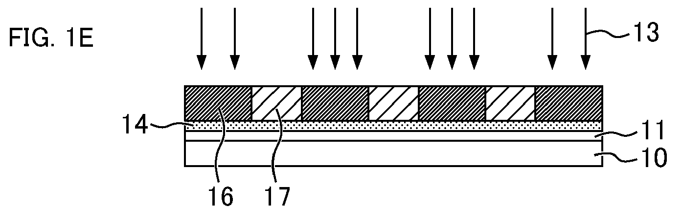
FIG. 1E is a view showing the formation of the exposedarea 16 and theunexposed area 17 in a photosensitive compositionthick film 15 by regioselective irradiation ofexposure light 13 to the photosensitive compositionthick film 15 included in asubstrate 10. -
FIG. 1F is a view showing the development of a photosensitive compositionthick film 15 including the exposedarea 16 and theunexposed area 17 with a developingsolution 18. -
FIG. 1G is a view showing asubstrate 10 including asacrificial film 11, athin film 14, and asupport film 19. -
FIG. 1H is a view showing detaching of amembrane filter 21 from asubstrate 10 by immersion of amembrane filter 21 including athin film 14 formed on thesubstrate 10 via asacrificial film 11, and asupport film 19 in adissolving solution 20. -
FIGs. 2A to 2C are view schematically showing a second method of a method for producing a membrane filter according to the present invention. -
FIG. 2A is a view showing asubstrate 10 including asacrificial film 11 and athin film 14, and a substrate including asacrificial film 11 and asupport film 19. -
FIG. 2B is a view showing bonding of athin film 14 formed on eachdifferent substrate 10, with asupport film 19. -
FIG. 2C is a view showing detaching of amembrane filter 21 from asubstrate 10 by immersion of amembrane filter 21 composed of athin film 14 formed between twosubstrates 10 via asacrificial film 11, and asupport film 19 in adissolving solution 20. -
FIGs. 3A to 3F are view schematically showing a third method of a method for producing a membrane filter according to the present invention. -
FIG. 3A is a view showing asubstrate 10 including asacrificial film 11 and a photosensitive compositionthin film 12. -
FIG. 3B is a view showing the formation of the exposedarea 16 and theunexposed area 17 in a photosensitive compositionthin film 12 by regioselective irradiation ofexposure light 13 to the photosensitive compositionthin film 12 included in asubstrate 10. -
FIG. 3C is a view showing the development of a photosensitive compositionthin film 12 including the exposedarea 16 and theunexposed area 17 with a developingsolution 18. -
FIG. 3D is a view showing asubstrate 10 including asacrificial film 11 and athin film 14 having through holes, and asubstrate 10 including asacrificial film 11 and asupport film 19. -
FIG. 3E is a view showing bonding of a thin film having throughholes 14 formed on eachdifferent substrate 10, with asupport film 19. -
FIG. 3F is a view showing detaching of amembrane filter 21 from asubstrate 10 by immersion of amembrane filter 21 composed of athin film 14 having through holes formed between twosubstrates 10 via asacrificial film 11, and asupport film 19 in adissolving solution 20. -
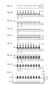
FIGs. 4A to 4I are view schematically showing modification of a first method of a method for producing a membrane filter. -
FIG. 4A is a view showing asubstrate 10 including asacrificial film 11 and a photosensitive compositionthin film 12. -
FIG. 4B is a view schematically showing the formation of the exposedarea 16 and theunexposed area 17 in a photosensitive compositionthin film 12 by regioselective irradiation of exposure light 13 to the photosensitive compositionthin film 12 included in asubstrate 10. -
FIG. 4C is a view schematically showing the development of a photosensitive compositionthin film 12 containing the exposedarea 16 and theunexposed area 17 with a developingsolution 18. -
FIG. 4D is a view schematically showing asubstrate 10 including asacrificial film 11, and athin film 14 having through holes. -
FIG. 4E is a view schematically showing asubstrate 10 including asacrificial film 11, athin film 14 having through holes, and a photosensitive compositionthick film 15 formed onthin film 14. -
FIG. 4F is a view showing the formation of the exposedarea 16 and theunexposed area 17 in a photosensitive compositionthick film 15 by regioselective irradiation of exposure light 13 to the photosensitive compositionthick film 15 included in asubstrate 10 with. -
FIG. 4G is a view schematically showing the development of a photosensitive compositionthick film 15 containing the exposedarea 16 and theunexposed area 17 with a developingsolution 18. -
FIG. 4H is a view schematically showing amembrane filter 21 composed of athin film 14 having through holes formed on asubstrate 10 via asacrificial film 11, an asupport film 19. -
FIG. 4I is a view schematically showing detaching of amembrane filter 21 from asubstrate 10 by immersion of amembrane filter 21 including athin film 14 having through holes formed on asubstrate 10 via asacrificial film 11, and asupport film 19 in adissolving solution 20. - The membrane filter according to the present invention is a membrane filter in which a thin film and a support film supporting the thin film are laminated with each other. The thin film has a thickness of 1 to 1,000 nm. The support film is made of a photosensitive composition or a cured product of the photosensitive composition. Therefore, the support film is typically a porous film having a thickness of 1 to 1,000 nm, which has a plurality of hole portions penetrating in the thickness direction, formed by exposure and development of a photosensitive composition film made of a photosensitive composition. Hereinafter, with respect to the thin film and the support film, hole portions penetrating in the thickness direction are also referred to as through holes.
- Since the thin film and the support film can be easily formed by applying a resin solution or a liquid photosensitive composition, it is easy for the membrane filter according to the present invention to achieve the enlargement of the area. The thin film and the support film will be described in due order below.
- The thin film has a thickness of 1 to 1,000 nm. It is easy to reconcile the strength of the thin film and satisfactory permeability of the membrane filter, so that the thin film preferably has a thickness of 5 to 1,000 nm. Since thin film is extremely thin, even when through holes and vacancies are not present, the thin film enables permeation of various molecules composing a gas and a liquid according to the size of the gap formed between molecules of the material composing the thin film.
- If necessary, the thin film may be formed with a plurality of hole portions penetrating in the thickness direction. Since it is easy to form hole portions, the thin film is preferably made of a photosensitive composition or a cured product of the photosensitive composition. In this case, the photosensitive composition film made of the photosensitive composition is preferably exposed and developed to form a thin film having the above-mentioned hole portions. Formation of plural through holes in the thin film enables permeation of a membrane filter for substances of relatively large size which cannot permeate a thin film having through hole. When thin film has through holes, it is possible to defiantly separate a liquid containing particles having the size larger than that of through holes into particles and a liquid using a membrane filter.
- When the photosensitive composition film is exposed and developed to form a thin film having hole portions, a thin film having hole portions with precisely controlled opening diameter can be formed, thus enabling microfiltration using a membrane filter.
- There is no particular limitation on the material for formation of a thin film, and the material may be either an organic material or an inorganic material. Because of its excellent processability and flexibility, typically, the material is preferably a polymer material. Examples thereof include solutions of various resins, a thermosetting composition, a photosensitive composition, and the like. The photosensitive composition includes a positive photosensitive composition in which the exposed area is solubilized in a developing solution, and negative photosensitive composition in which the exposed area is insolubilized in a developing solution. Both photosensitive compositions can be used to form a thin film.
- The material for formation of a thin film is preferably a thermosetting composition capable of curing under heating, or a negative photosensitive composition capable of curing under exposure from the viewpoint being capable of forming a thin film having excellent strength. Of these curable compositions, a negative photosensitive composition capable of curing under exposure is preferable since a thin film can be formed within a short time.
- There is no particular limitation on the composition of the thermosetting composition, as long as a thin film having a desired thickness can be formed. Examples of preferred thermosetting composition include a liquid composition containing an epoxy compound, and a curing agent for thermally curing the epoxy compound, and the like. Preferred examples of the negative photosensitive composition capable of curing under exposure include a composition containing an epoxy compound and a photosensitive curing agent, a composition containing an alkali-soluble resin, a photopolymerizable compound having an unsaturated double bond, and a photopolymerization initiator, and the like.
- When the thin film has plural through holes, there is no particular limitation on the shape of the opening on a surface of the thin film corresponding to both ends of through holes. Examples of the shape of the opening include polygons such as triangle (for example, regular triangle), tetragon (for example, square), and hexagon (for example, regular hexagon), circle, oval, and the like. The shape of the opening is preferably a circle since it is not easy to inhibit permeation of substances having a desired size and it is easy to inhibit permeation of substances having a size larger than the desired size. The above-mentioned shapes such as regular triangle, square, regular hexagon, circle, and oval may be the shape which can be visually recognized as these shapes, and there is no limitation on these shapes defined geometrically.
- There is no particular limitation on the average diameter the opening of through holes, and the average diameter is appropriately decided according to the size of a separation target. Typically, the average diameter of the opening is preferably 1 nm to 100 µm, more preferably 5 nm to 50 µm, and particularly preferably 10 nm to 20 µm. The average diameter of the opening is a circle equivalent diameter calculated based on the area of the opening.
- The thin film may be formed with either through holes having two or more openings each having a different shape, or through holes having two or more openings each having a different size.
- The support film is formed by exposure and development of a photosensitive composition film made of a photosensitive composition. The support film porous film having a thickness of 1 to 1,000 µm, which has a plurality of hole portions penetrating in the thickness direction. It is easy to reconcile the strength of the support film and satisfactory permeability of the membrane filter, so that the support film preferably has a thickness of 5 to 1,000 nm.
- The support film is thicker than the thin film, and also has numerous through holes. Therefore, the membrane filter produced by laminating the thin film with the support film is less likely to be broken by a force applied at the time of handling of the membrane filter, or a pressure applied to the membrane filter in the case of permeation of a gas or liquid, while satisfactorily enabling permeation of a gas or liquid fed to the membrane filter.
- It is possible to use, as the photosensitive composition for formation of the support film, both a positive photosensitive composition in which the exposed area is solubilized in the developing solution, and a negative photosensitive composition in which the exposed area is insolubilized in the developing solution. The material for formation of the support film is preferably a negative photosensitive composition which is cured under exposure from the viewpoint being capable of forming a thin film having excellent strength. Suitable examples of the negative photosensitive composition include the same materials as those for formation of the thin film.
- The support film has plural through holes. There is no particular limitation on the shape of the opening on a surface of the support film corresponding to both ends of through holes. Examples of the shape of the opening are the same as those of the shape of the opening of through holes which may be possessed by the thin film.
- There is no particular limitation on the average diameter of the opening of through holes, and the average diameter can be appropriately decided according to the size of a separation target, the strength of the thin film, and the area to be used of the entire filter.
- The support film may be formed with either through holes having two or more openings each having a different shape, or through holes having two or more openings each having a different size.
- There is no particular limitation on the method for producing a membrane filter, as long as it is a method capable of laminating a thin film with a support film, each having a predetermined configuration. Preferred method for producing a membrane filter will be described below by way of a first method, a second method, and a third method.
- Of the method for producing a membrane filter according to the present invention, a preferred method when a
thin film 14 has not through holes includes a method in which athin film 14 is formed on asubstrate 10 and a thick film of a photosensitive composition (hereinafter also referred to as the photosensitive composition thick film 15) is formed on thethin film 14, and then the thus formed photosensitive compositionthick film 15 is exposed and developed to form asupport film 19. This method is referred to as the first method of the preferred method for producing amembrane filter 21. - The material for formation of a
thin film 14 is preferably a thermosetting composition capable of curing under heating, or a negative photosensitive composition capable of curing under exposure from the viewpoint being capable of forming athin film 14 having excellent strength. Of these curable compositions, a negative photosensitive composition capable of curing under exposure is preferable since athin film 14 can be formed within a short time. - Because of easy detaching of the membrane filter formed by laminating a
support film 19 on thethin film 14 from thesubstrate 10, thethin film 14 is preferably formed on thesubstrate 10 via asacrificial film 11 made of a material which dissolves in a liquid. - Using a negative photosensitive composition capable of curing under exposure, which is preferable in the first method, a method including a step of forming a
thin film 14 on asubstrate 10 via asacrificial film 11 will be described with reference toFIGs. 1A to 1H . - First, as shown in
FIG. 1A , asacrificial film 11 is formed on asubstrate 10. There is no particular limitation on the material of thesubstrate 10 as long as it is not a material which is attacked with or dissolved in an organic solvent contained in the photosensitive composition or a liquid for dissolving asacrificial film 11. Examples of the material of thesubstrate 10 include silicone, glass, PET film, and the like. - There is no particular limitation on the method for forming a
sacrificial film 11, and the method is preferably a method in which a coating solution for formation of a sacrificial film is applied on thesubstrate 10. Examples of the method for applying a material for formation of liquid sacrificial film on asubstrate 10 include a method using a contact transfer type coating device such as a roll coater, a reverse coater, or a bar coater, or a non-contact type coating device such as a spinner (rotary coating device) or a curtain flow coater. Asacrificial film 11 is formed by drying a coating film formed after application using a method such as heating. There is no particular limitation on the thickness of thesacrificial film 11, and the thickness is preferably 0.1 to 100 µm, and more preferably 0.5 to 50 µm, from the viewpoint of quickly dissolving thesacrificial film 11. - Examples of the material of the
sacrificial film 11 include polyvinyl alcohol resin, dextrin, gelatin, glue, casein, serac, gum arabic, starch, protein, polyacrylic acid amide, sodium polyacylate, polyvinyl methyl ether, copolymer of methyl vinyl ether with maleic anhydride, copolymer of vinyl acetate with itaconic acid, polyvinylpyrrolidone, acetyl cellulose, hydroxyethyl cellulose, sodium alginate, and the like. Of these materials, a plurality of materials capable of being soluble in the same kind of a liquid may be used in combination. From the viewpoint of the strength and flexibility of thesacrificial film 11, the material of thesacrificial film 11 may contain rubber components such as mannan, xanthan gum, and guar gum. - The coating solution for formation of a sacrificial film is prepared by dissolving the above-described material of the
sacrificial film 11 in a liquid which can dissolve thesacrificial film 11. There is no particular limitation on the liquid which dissolves thesacrificial film 11, as long as it is a liquid which does not cause deterioration of or dissolve thethin film 14 and thesupport film 19. Examples of the liquid for dissolving thesacrificial film 11 include water, an aqueous acidic or basic solution, an organic solvent, and an aqueous solution of the organic solvent and, of these liquid, water, an aqueous acidic or basic solution, and an organic solvent are preferable. - Suitable examples of the liquid which dissolves the material of the
sacrificial film 11 material include an organic solvent. Examples of the organic solvent include lactones, ketones, polyhydric alcohols, organic solvent of cyclic ethers and esters, aromatic organic solvent, alcohol-based solvent, terpene-based solvent, hydrocarbon-based solvent, petroleum-based solvent, and the like. These organic solvents may be used alone, or plural kinds thereof may be used in combination. - Examples of the organic solvent of lactones include γ-butyrolactone, and the like. Examples of the organic solvent of ketones include acetone, methyl ethyl ketone, cycloheptanone, cyclohexanone, methyl-n-pentyl ketone, methyl isopentyl ketone, 2-heptanone, and the like. Examples of the organic solvent of polyhydric alcohols include ethylene glycol, diethylene glycol, propylene glycol, dipropylene glycol, and the like.
- The organic solvent of polyhydric alcohols may be derivatives of polyhydric alcohols, and examples thereof include compounds having an ester bond (ethylene glycol monoacetate, diethylene glycol monoacetate, propylene glycol monoacetate, dipropylene glycol monoacetate, etc.), compounds having an ether bond (monoalkyl ether or monophenyl ether, such as monomethyl ether, monoethyl ether, monopropyl ether, or monobutyl ether) of the above-mentioned polyhydric alcohols or the above-mentioned compounds having an ester bond), and the like. Of these, propylene glycol monomethyl ether acetate (PGMEA) and propylene glycol monomethyl ether (PGME) are preferable.
- Examples of the organic solvent of cyclic ethers include dioxane, and the like; and examples of the organic solvent of esters include ethyl lactate, ethyl lactate (EL), methyl acetate, ethyl acetate, butyl acetate, methyl pyruvate, ethyl pyruvate, methyl methoxypropionate, ethyl ethoxypropionate, and the like.
- Examples of the aromatic organic solvent include anisole, ethyl benzyl ether, cresyl methyl ether, diphenyl ether, dibenzyl ether, phenetole, butyl phenyl ether, ethylbenzene, diethylbenzene, pentylbenzene, isopropylbenzene, toluene, xylene, cymene, mesitylene, and the like.
- There is no particular limitation on the alcohol-based solvent, as long as it can dissolve a
sacrificial film 11, and examples thereof include methanol, ethanol, and the like. - Examples of the terpene-based solvent include geraniol, nerol, linalool, citral, citronellol, menthol, isomenthol, neomenthol, α-terpineol, β-terpineol, γ-terpineol, terpinen-1-ol, terpinen-4-ol, dihydroterpinyl acetate, 1,4-cineole, 1,8-cineole, borneol, carvone, ionone, thujone, camphor, and the like.
- Examples of the hydrocarbon-based solvent include a linear, branched, or cyclic hydrocarbon. Examples of the hydrocarbon-based solvent include linear hydrocarbons having 3 to 15 carbon atoms, such as hexane, heptane, octane, nonane, decane, undecane, dodecane, and tridecane; branched hydrocarbons having 4 to 15 carbon atoms, such as methyloctane; and cyclic hydrocarbons such as p-menthane, o-menthane, m-menthane, diphenylmenthane, 1,4-terpin, 1,8-terpin, bornane, norbornane, pinane, thujane, carane, longifolene, α-terpinene, β-terpinene, γ-terpinene, α-pinene, β-pinene, α-thujone, and β-thujone.
- Examples of the petroleum-based solvent include cyclohexane, cycloheptane, cyclooctane, naphthalene, decahydronaphthalene (decalin), tetrahydronaphthalene (tetralin), and the like.
- Next, as shown in
FIG. 1B , a liquid negative photosensitive composition is applied on a surface of thesacrificial film 11 thus formed as mentioned above to form a photosensitive compositionthin film 12. The method for applying a negative photosensitive composition on a surface of thesacrificial film 11 is the same as that in which a coating solution for formation of a sacrificial film is applied on a surface of asubstrate 10. The thickness of the photosensitive compositionthin film 12 is appropriately adjusted so as to form athin film 14 having a thickness of 1 to 1,000 nm. - As shown in
FIG. 1C , the photosensitive compositionthin film 12 is cured by irradiation of exposure light 13 to the photosensitive compositionthin film 12 to form athin film 14. There is no particular limitation on the method for exposing the photosensitive compositionthin film 12, and exposure is performed by a known method in which a photocurable photosensitive composition is cured. - When the
substrate 10 is made of a transparent material like a glass substrate, the photosensitive compositionthin film 12 can also be exposed from a surface opposite to the surface on which thesacrificial film 11 and the photosensitive compositionthin film 12 of thesubstrate 10 are formed. - After formation of the
thin film 14, as shown inFIG. 1D , a photosensitive compositionthick film 15 is formed on thethin film 14. The photosensitive compositionthick film 15 is preferably formed by applying a liquid photosensitive composition on thethin film 14. The method for applying a photosensitive composition on a surface of thethin film 14 is the same as that in which a coating solution for formation of a sacrificial film is applied on a surface of asubstrate 10. The thickness of the photosensitive compositionthick film 15 is appropriately adjusted so as to form asupport film 19 having a thickness of 1 to 1,000 µm. - Next, a photosensitive composition
thick film 15 is regioselectively exposed and developed to form asupport film 19 which is a porous film.FIG. 1E shows the case where the photosensitive compositionthick film 15 is formed by using a negative photosensitive composition which is cured under exposure. There is no particular limitation on the method in which a surface of the photosensitive compositionthick film 15 is regioselectively exposed, and examples thereof include a drawing method using laser, a method in which exposure is performed through a light-shielding mask, and the like. As shown inFIG. 1E , according to this method, the exposedarea 16 and theunexposed area 17 are formed in the photosensitive compositionthick film 15 by regioselectively irradiation of exposure light 13 to a surface of the photosensitive compositionthick film 15. - When the
substrate 10 is made of a transparent material like a glass substrate, the photosensitive compositionthick film 15 can also be exposed from a surface opposite to the surface on which thesacrificial film 11 and thethin film 14 of thesubstrate 10 are formed. - As shown in
FIG. 1F and FIG. 1G , theunexposed area 17 is dissolved and removed to form asupport film 19 by bringing the exposed photosensitive compositionthick film 15 into contact with a developingsolution 18 to thereby develop the thick film. Amembrane filter 21 in which athin film 14 and asupport film 19 are laminated with each other on asubstrate 10 is formed by forming thesupport film 19 in this way. - The developing
solution 18 is appropriately selected according to the kind of the photosensitive composition. Typically, a developing solution of an organic solvent and an alkali developing solution are preferably used. - Examples of the organic solvent used as the developing
solution 18 include polar solvents such as a ketone-based solvent, an ester-based solvent, an ether-based solvent, and an amide-based solvent; and a hydrocarbon-based solvent. - It is possible to use, as the alkali developing solution, for example, an aqueous solution of alkalis such as sodium hydroxide, potassium hydroxide, sodium carbonate, sodium silicate, sodium metasilicate, aqueous ammonia, ethylamine, n-propylamine, diethylamine, di-n-propylamine, triethylamine, methyldiethylamine, dimethylethanolamine, triethanolamine, tetramethylammonium hydroxide, tetraethylammonium hydroxide, pyrrole, piperidine, 1,8-diazabicyclo[5,4,0]-7-undecene, 1,5-diazabicyclo[4,3,0]-5-nonane, and the like. It is also possible to use, as the alkali developing solution, an aqueous solution prepared by adding an appropriate amount of a watersoluble organic solvent such as methanol or ethanol, and a surfactant to the above aqueous solutions of alkalis.
- The developing time varies depending on the composition, thickness, and the like of the photosensitive composition
thick film 15, and is usually 1 to 30 minutes. The developing method may be selected from a known method, and may be a liquid building-up method, a dipping method, a puddle method, a spray developing method, and the like. - As shown in
FIG. 1H , thesubstrate 10 including themembrane filter 21 thus formed is brought into contact with a dissolvingsolution 20 which dissolves asacrificial film 11 to thereby dissolve thesacrificial film 11, thus enabling detaching of themembrane filter 21 from a surface of thesubstrate 10. - There is no particular limitation on the method for dissolving the
sacrificial film 11. As shown inFIG. 1H , the method is preferably a method in which thesubstrate 10 including thesacrificial film 11 and themembrane filter 21 is immersed in a container charged with the dissolvingsolution 20. - It is possible to use, as the dissolving
solution 20 which dissolves thesacrificial film 11, various liquid capable of dissolving the above-mentioned material of thesacrificial film 11. - The
membrane filter 21 thus detached from thesubstrate 10 is pulled up from the dissolvingsolution 20 and optionally subjected to rinsing with deionized water and dried, and then used for various applications. - Of the method for producing a membrane filter according to the present invention, a preferred method which is different from the first method when a
thin film 14 has not through holes includes a method in which thethin film 14 formed on thesubstrate 10 is bonded to a surface of asupport film 19 formed on thesubstrate 10 which is different from that including thethin film 14. This method is referred to as a second method of a preferred method for producing amembrane filter 21. - The material for formation of the
thin film 14 in the same manner as in first method is preferably a thermosetting composition capable of curing under heating, or a negative photosensitive composition capable of curing under exposure from the viewpoint being capable of forming athin film 14 having excellent strength. Of these curable compositions, a negative photosensitive composition capable of curing under exposure is preferable since athin film 14 can be formed within a short time. - In the second method, it is possible to form a
membrane filter 21 in which thethin film 14 and thesupport film 19 are laminated with each other between twosubstrates 10. Themembrane filter 21 is used in a state of being detached from twosubstrates 10. Therefore, since it is easy to detach twosubstrates 10 from themembrane filter 21, it is preferred that thethin film 14 and thesupport film 19 are respectively formed on thesubstrate 10 via asacrificial film 11. - Using a negative photosensitive composition capable of curing under exposure, which is preferred in the second method, a description will be made of a method including a step of bonding a
thin film 14 formed on asubstrate 10 via asacrificial film 11 to asupport film 19 formed on asubstrate 10 via asacrificial film 11 with reference toFIGs. 2A to 2C . - In the second method, first, as shown in
FIG. 2A , athin film 14 formed on asubstrate 10 via asacrificial film 11 and asupport film 19 formed on asubstrate 10 via asacrificial film 11 are prepared. The method for forming athin film 14 is the same as the first method. The method for forming asupport film 19 is the same as the first method, except that a photosensitive compositionthick film 15 is not formed on thethin film 14, but on thesacrificial film 11. - Next, a
thin film 14 formed on asubstrate 10 via asacrificial film 11 and asupport film 19 formed on asubstrate 10 via asacrificial film 11 are disposed so that thethin film 14 and thesupport film 19 face each other, and then thesupport film 19 is bonded with thethin film 14. Examples of the method for bonding thesupport film 19 with thethin film 14 include a method in which laminate (thermocompression bonding), physical adsorption, and adhesive such as a curable compound are used as an adhesive layer. For example, thesupport film 19 may be bonded with thethin film 14 by applying a pressure to at least onesubstrate 10 so as not to cause breakage of thesupport film 19 or thethin film 14, using a roll. Such bonding operation enables the formation of amembrane filter 21 in which thethin film 14 and thesupport film 19 are laminated with each other between twosubstrates 10, as shown inFIG. 2B . - As shown in
FIG. 2C , themembrane filter 21 thus formed between twosubstrates 10 is brought into contact with a dissolvingsolution 20 which dissolves asacrificial film 11 to thereby dissolve thesacrificial film 11, thus enabling detaching ofmembrane filter 21 from a surface of twosubstrates 10. - There is no particular limitation on the method for dissolving the
sacrificial film 11. The method is preferably a method in which asubstrate 10 including thesacrificial film 11 and themembrane filter 21 is immersed in a container charged with the dissolvingsolution 20, as shown inFIG. 1H . In this case, after dissolution of thesacrificial film 11, wrinkles and flaws sometimes occur in thedetached membrane filter 21 due to the own weight of thesubstrate 10. Therefore, in the case of dissolving thesacrificial film 11, it is preferred that thesubstrate 10 of the liquid surface side of the dissolvingsolution 20 is fixed so as not to move in thedissolving solution 20, or both twosubstrates 10 are fixed so as not to freely remove in thedissolving solution 20. - It is possible to use, as the dissolving
solution 19 for dissolving thesacrificial film 11, various liquids capable of dissolving the above-mentioned materials of thesacrificial film 11. - The
membrane filter 21 thus detached from thesubstrate 10 is pulled up from the dissolvingsolution 20 and optionally subjected to rinsing with deionized water and drying, and then used for various applications. - Of the method for producing a membrane filter according to the present invention, a preferred method when a
thin film 14 has through holes includes a method in which thethin film 14 formed on thesubstrate 10 is bonded to a surface of asupport film 19 formed on thesubstrate 10 which is different from that including thethin film 14. This method is referred to as a third method of a preferred method for producing amembrane filter 21. - It is possible to use, as the material for formation of the
thin film 14, a photosensitive composition so as to form through holes. From the viewpoint being capable of forming athin film 14 having through holes, which is excellent in strength, by exposure and development of a photosensitive compositionthin film 12, the material for formation of athin film 14 is preferably negative photosensitive composition which is cured under exposure. - In third method, it is possible to form a
membrane filter 21 in which thethin film 14 and thesupport film 19 are laminated with each other between twosubstrates 10. Themembrane filter 21 is used in the state of being detached from twosubstrates 10. Therefore, since it is easy to detach twosubstrates 10 from themembrane filter 21, it is preferred that thethin film 14 and thesupport film 19 are respectively formed on thesubstrate 10 via asacrificial film 11. - Using a negative photosensitive composition capable of curing under exposure, which is preferred in the third method, a description will be made of a method including a step of bonding a
thin film 14 formed on asubstrate 10 via asacrificial film 11 to asupport film 19 formed on asubstrate 10 via asacrificial film 11 with reference toFIGs. 3A to 3F . - First, a method for forming a
thin film 14 having through holes will be described. When athin film 14 having through holes is formed, first, as shown inFIG. 3A , a photosensitive compositionthin film 12 is formed on a surface of thesacrificial film 11 formed on thesubstrate 10 in the same manner as in the first method. - Next, as shown in
FIG. 3B , the photosensitive compositionthin film 12 is regioselectively exposed. Such exposure enables the formation of the exposedarea 16 and theunexposed area 17 in the photosensitive compositionthin film 12. Exposing method is the same as the method of exposure to photosensitive compositionthick film 15 in the first method. - As shown in
FIG. 3C and FIG. 3D , the exposed photosensitive compositionthin film 12 is brought into contact with a developingsolution 18 to thereby develop the thin film, and thus theunexposed area 17 is dissolved and removed to form athin film 14 having through holes. - As shown in
FIG. 3D , in addition to the above-describedthin film 14 having through holes, asupport film 19 formed on asubstrate 10 via asacrificial film 11 in the same manner as in the second method is prepared. - Next, a
thin film 14 formed on asubstrate 10 via asacrificial film 11 and asupport film 19 formed on asubstrate 10 via asacrificial film 11 are disposed so that thethin film 14 and thesupport film 19 face each other, and then an external force is applied to at least onesubstrate 10 so that thesupport film 19 is contact-bonded with thethin film 14. As a result, it is possible to form amembrane filter 21 in which athin film 14 having through holes and asupport film 19 are laminated with each other between twosubstrates 10, as shown inFIG. 3E . - As shown in
FIG. 3F , themembrane filter 21 formed between twosubstrates 10 in the same manner as in the second method is brought into contact with a dissolvingsolution 20 which dissolves asacrificial film 11 to thereby dissolve thesacrificial film 11, thus enabling detaching of themembrane filter 21 from a surface of twosubstrates 10. - The
membrane filter 21 thus detached from thesubstrate 10 is pulled up from the dissolvingsolution 20 and optionally subjected to rinsing with deionized water and drying, and then used for various applications. - Modification of a first method will be described with reference to
FIGs. 4A to4I. According to the third method, two substrates are needed so as to produce a membrane filter in which a thin film having through holes and a support film having through holes are laminated with each other. However, according to modification of the first method, use of only one substrate enables the production of a membrane filter in which a thin film having through holes and a support film having through holes are laminated with each other. - Specifically, first, as shown in
FIG. 4A , a photosensitive compositionthin film 12 is formed on a surface of asacrificial film 11 formed on asubstrate 10 in the same manner as in the first method. - Next, as shown in
FIG. 4B , a photosensitive compositionthin film 12 is regioselectively exposed. Such exposure enables the formation of the exposedarea 16 and theunexposed area 17 in the photosensitive compositionthin film 12. The exposing method is the same as the method of exposure to a photosensitive compositionthick film 15 in the first method. - As shown in
FIG. 4C and FIG. 4D , the exposed photosensitive compositionthin film 12 is brought into contact with a developingsolution 18 to thereby develop the thin film, and thus theunexposed area 17 is dissolved and removed to form athin film 14 having through holes. - After forming the
thin film 14 having through holes, as shown inFIG. 4E , a photosensitive compositionthick film 15 is formed on thethin film 14. At this time, a photosensitive compositionthick film 15 is formed so as to fill through holes in thethin film 14 with a photosensitive composition. The photosensitive compositionthick film 15 is formed in the same manner as in the first method. - The photosensitive composition filled in through holes of the
thin film 14 is removed by dissolving in a developingsolution 18 in the case of developing the exposed photosensitive compositionthick film 15 with the developingsolution 18. Therefore, in the case of forming a photosensitive compositionthick film 15, it is not necessary that through holes inthin film 14 are completely filled with a photosensitive composition. - Next, as shown in
FIG. 4F and FIG. 4G , the photosensitive compositionthick film 15 is regioselectively exposure and then developed to form asupport film 19 which is a porous film. - In the present modification, the photosensitive composition
thick film 15 is regioselectively exposed so as to completely expose the photosensitive composition filled in through holes of thethin film 14. Therefore, in the case of developing the exposed photosensitive compositionthick film 15 with a developingsolution 18, the photosensitive composition filled in through holes in thethin film 14 is dissolved in the developingsolution 18, together with the exposedarea 16 formed in the photosensitive compositionthick film 15. - The above-mentioned developing operation enables the production of a
membrane filter 21, in which thethin film 14 having through holes and thesupport film 19 having through holes are laminated with each other, included in thesubstrate 10 via thesacrificial film 11, as shown inFIG. 4H . - As shown in
FIG. 4I , themembrane filter 21 thus formed is brought into contact with a dissolvingsolution 20 which dissolves asacrificial film 11 to thereby dissolve thesacrificial film 11, thus enabling detaching of themembrane filter 21 from a surface of twosubstrates 10. - The
membrane filter 21 thus detached from thesubstrate 10 is pulled up from the dissolvingsolution 20 and optionally subjected to rinsing with deionized water and drying, and then used for various applications. - On a substrate made of glass, a solution (solid content: 10% by mass) prepared by dissolving a thermoplastic elastomer having a structure shown below as a hydrogenated styrene-isoprene copolymer in decahydronaphthalene was applied, and then baked under the conditions of 90°C for 5 minutes and 120°C for 5 minutes to form a sacrificial film having a thickness of 1.5 µm.
-

- Next, on the sacrificial film, a negative photosensitive composition prepared by dissolving 100 parts by mass of a cresol novolak type epoxy resin having a structure shown below and 3 parts by mass of a photo acid generator having a structure shown below in propylene glycol monomethyl ether acetate (PGMEA) so as to adjust the solid content to 7% by mass was applied. Next, baking at 90°C for 3 minutes, exposure to ghi-line at an exposure dose of 100 mJ/cm2, and baking at 120°C for 5 minutes were performed in this order to form a thin film having a thickness of 100 nm.
-

-

- On the thin film thus formed, a negative photosensitive composition prepared by dissolving 50 parts by mass of a phenol novolak type epoxy resin having a structure shown below, 50 parts by mass of a bisphenol A type epoxy resin having a structure shown below, and 3 parts by weight of a photo acid generator having a structure shown below in PGMEA so as to adjust the solid content to 50% by mass was applied. Next, baking at 90°C for 3 minutes, exposure to ghi-line at an exposure dose of 200 mJ/cm2, and baking at 90°C for 5 minutes were performed in this order. Exposure was regioselectively performed through a mask so as to form circular holes each having a pore diameter of 10 µm at a pitch (a distance between centers of holes) of 50 µm. After exposure, the substrate was immersed in PGMEA for 1 minute to thereby perform development to form a 10 µm thick support film including holes each having a circular opening with the above-mentioned diameter and pitch.
-

-

- Next, the substrate with a membrane filter including a thin film and a support film laminated with each other was dissolved in p-menthane at room temperature for 1 hour to thereby dissolve the sacrificial film, and then the membrane filter was detached from the substrate. The detached membrane filter was recovered, rinsed with deionized water, and then dried.
- The membrane filter thus obtained was fixed to a jig and a nitrogen gas was fed from the support film side of the membrane filter under the conditions where the pressure difference between both sides of the membrane filter of 0.05 MPa. As a result, a nitrogen flow rate of 100 ml/minute was recognized. After a confirmation test of the nitrogen flow rate, breakage of the membrane filter was not recognized, thus revealing that the membrane filter obtained in Example 1 is excellent in strength.
- In the same manner as in Examples, except that a thickness of a thin film is adjusted to 1,500 nm, a membrane filter was obtained. In the same manner as in Example, regarding the obtained membrane filter, the nitrogen flow rate was recognized when a differential pressure of 0.05 MPa was applied. As a result, the nitrogen flow rate was 0 ml/minute. In other words, the membrane filter of Comparative Example did not enable permeation of nitrogen at a differential pressure of 0.05 MPa.
-
- 10: Substrate (first substrate or second substrate)
- 11: Sacrificial film (first sacrificial film or second sacrificial film)
- 12: Photosensitive composition thin film (second photosensitive composition film)
- 13: Exposure light
- 14: Thin film
- 15: Photosensitive composition thick film (first photosensitive composition film)
- 16: Exposed area
- 17: Unexposed area
- 18: Developing solution
- 19: Support film
- 20: Dissolving solution
- 21: Membrane filter
Claims (14)
- A membrane filter (21) characterized in that it comprises:a thin film (14) and a support film (19) supporting the thin film (14), whereinthe thin film (14) and the support film (19) are laminated with each other,the thin film (14) has a thickness of 1 to 1,000 nm,the support film (19) is a porous film having a thickness of 1 to 1,000 µm and a plurality of hole portions penetrating in the thickness direction, andthe support film (19) is made of a photosensitive composition or a cured product of the photosensitive composition.
- The membrane filter (21) according to claim 1, wherein the support film (19) is formed by exposure and development of a photosensitive composition film.
- The membrane filter (21) according to claim 1 or 2, wherein the thin film (14) does not have the hole portion penetrating in the thickness direction.
- The membrane filter (21) according to claim 1 or 2, wherein
the thin film (14) is a resin film having a plurality of hole portions penetrating in the thickness direction, and
the thin film (14) is made of a photosensitive composition or a cured product of the photosensitive composition. - The membrane filter (21) according to claim 4, wherein the thin film (14) is formed by exposure and development of a photosensitive composition film.
- A method for producing a membrane filter (21) characterized in that it comprises:laminating a thin film (14) and a support film (19) supporting the thin film (14), whereinthe thin film (14) has a thickness of 1 to 1,000 nm,the support film (19) is a porous film having a thickness of 1 to 1,000 µm and a plurality of hole portions penetrating in the thickness direction, andthe support film (19) is formed by exposure and development of a first photosensitive composition film (15).
- The method according to claim 6, further comprising:forming the first photosensitive composition film (15) on the thin film (14), andforming the support film (19) by exposure and development of the first photosensitive composition film (15), whereinthe thin film (14) is laminated with a first substrate (10).
- The method according to claim 7, wherein
the thin film (14) is formed on a first sacrificial film (11) that is formed on the first substrate (10),
the method further comprising:detaching the membrane filter (21) from the first substrate (10) by dissolving the first sacrificial film (11) in a dissolving solution (20). - The method according to claim 6, further comprising:laminating the first photosensitive composition film (15) with a second substrate (10), whereinthe thin film (14) is laminated with a first substrate (10).
- The method according to claim 9, wherein
the thin film (14) is formed on a first sacrificial film (11) that is formed on the first substrate (10), and
the support film (19) is formed on a second sacrificial film (11) that is formed on the second substrate (10),
the method further comprising:detaching the membrane filter (21) from the first substrate (10) by dissolving the first sacrificial film (11) in a dissolving solution (20), and also from the second substrate (10) by dissolving the second sacrificial film (11) in a dissolving solution (20). - The method according to claim 6, further comprising:laminating a second photosensitive composition film (12) with a first substrate (10),forming the thin film (14) by exposure and development of the second photosensitive composition film (12), andlaminating the first photosensitive composition film (15) with a second substrate (10), whereinthe thin film (14) is a resin film having a plurality of hole portions penetrating in the thickness direction.
- The method according to claim 11, wherein
the thin film (14) is formed on a first sacrificial film (11) that is formed on the first substrate (10), and
the support film (19) is formed on a second sacrificial film (11) that is formed on the second substrate (10),
the method further comprising:detaching the membrane filter (21) from the first substrate (10) by dissolving the first sacrificial film (11) in a dissolving solution (20), and also from the second substrate (10) by dissolving the second sacrificial film (11) in a dissolving solution (20). - The method according to claim 6, further comprising:laminating a second photosensitive composition film (12) with a first substrate (10),forming the thin film (14) by exposure and development of the second photosensitive composition film (12),forming the first photosensitive composition film (15) on the thin film (14), wherein the hole portions in the thin film (14) is filled with a photosensitive composition,regioselectively exposing the first photosensitive composition film (15), anddeveloping to remove the photosensitive composition filled in the hole portions, thereby the support film (19) is formed, whereinthe thin film (14) is a resin film having a plurality of hole portions penetrating in the thickness direction.
- The method according to claim 13, wherein
the thin film (14) is formed on a first sacrificial film (11) that is formed on the first substrate (10),
the method further comprising:detaching the membrane filter (21) from the first substrate (10) by dissolving the first sacrificial film (11) in a dissolving solution (20).
Applications Claiming Priority (1)
| Application Number | Priority Date | Filing Date | Title |
|---|---|---|---|
| JP2014133371A JP6359895B2 (en) | 2014-06-27 | 2014-06-27 | Membrane filter |
Publications (2)
| Publication Number | Publication Date |
|---|---|
| EP2977099A1 true EP2977099A1 (en) | 2016-01-27 |
| EP2977099B1 EP2977099B1 (en) | 2020-06-03 |
Family
ID=54011950
Family Applications (1)
| Application Number | Title | Priority Date | Filing Date |
|---|---|---|---|
| EP15173691.5A Active EP2977099B1 (en) | 2014-06-27 | 2015-06-24 | Method for forming a membrane filter made of photosensitive material |
Country Status (4)
| Country | Link |
|---|---|
| US (2) | US20150375176A1 (en) |
| EP (1) | EP2977099B1 (en) |
| JP (1) | JP6359895B2 (en) |
| KR (1) | KR102361841B1 (en) |
Cited By (4)
| Publication number | Priority date | Publication date | Assignee | Title |
|---|---|---|---|---|
| EP3073320A3 (en) * | 2015-03-26 | 2017-06-07 | Tokyo Ohka Kogyo Co., Ltd. | Laminated film |
| KR20170085445A (en) * | 2016-01-14 | 2017-07-24 | 도쿄 오카 고교 가부시키가이샤 | Method for producing laminate, and laminate |
| US10137665B2 (en) | 2016-01-14 | 2018-11-27 | Tokyo Ohka Kogyo Co., Ltd. | Method for manufacturing laminate, and laminate |
| EP3566774A1 (en) * | 2018-05-11 | 2019-11-13 | Tokyo Ohka Kogyo Co., Ltd. | Filter film and use thereof |
Families Citing this family (5)
| Publication number | Priority date | Publication date | Assignee | Title |
|---|---|---|---|---|
| JP6460658B2 (en) * | 2014-06-27 | 2019-01-30 | 東京応化工業株式会社 | Membrane filter |
| WO2019039242A1 (en) * | 2017-08-21 | 2019-02-28 | 東京応化工業株式会社 | Gas separation method and gas separation membrane |
| CN111569667A (en) * | 2020-05-21 | 2020-08-25 | 苏州研材微纳科技有限公司 | Preparation method of micron through hole array on PDMS film |
| KR102483728B1 (en) * | 2020-12-30 | 2023-01-02 | 금오공과대학교 산학협력단 | Membrane having ordered pores and manufacturing method thereof |
| CN114713051B (en) * | 2022-03-28 | 2023-06-27 | 金发科技股份有限公司 | Polyamide film, preparation method and application of photo-repairing polyamide film |
Citations (7)
| Publication number | Priority date | Publication date | Assignee | Title |
|---|---|---|---|---|
| WO2001041905A1 (en) * | 1999-12-08 | 2001-06-14 | Baxter International Inc. | Microporous filter membrane, method of making microporous filter membrane and separator employing microporous filter membranes |
| US20020162791A1 (en) * | 1999-12-08 | 2002-11-07 | Baxter International, Inc. | Method for fabricating three dimensional structures |
| JP2004057993A (en) * | 2002-07-31 | 2004-02-26 | Dainippon Printing Co Ltd | Method for producing filter for hydrogen production |
| US20060263548A1 (en) * | 2002-01-07 | 2006-11-23 | Thierry Lagarde | Method of producing a sheet comprising through pores and the application thereof in the production of micronic and submicronic filters |
| JP2008285617A (en) | 2007-05-21 | 2008-11-27 | Institute Of Physical & Chemical Research | Method for producing polymer thin film and polymer thin film |
| WO2013043124A1 (en) * | 2011-09-21 | 2013-03-28 | Nanyang Technological University | A multilayer filter |
| WO2013049936A1 (en) * | 2011-10-04 | 2013-04-11 | The University Of Western Ontario | Fabrication of free standing membranes and use thereof for synthesis of nanoparticle patterns |
Family Cites Families (7)
| Publication number | Priority date | Publication date | Assignee | Title |
|---|---|---|---|---|
| US7282148B2 (en) * | 2003-10-30 | 2007-10-16 | International Business Machines Corporation | Porous silicon composite structure as large filtration array |
| DE102009034575A1 (en) * | 2009-07-24 | 2011-01-27 | Universität Bielefeld | Perforated membranes |
| JP2011101837A (en) * | 2009-11-10 | 2011-05-26 | Fujifilm Corp | Separation membrane, and method of producing the same |
| JP6145982B2 (en) * | 2011-09-26 | 2017-06-14 | 東レ株式会社 | Method for producing composite semipermeable membrane and composite semipermeable membrane |
| US20140255638A1 (en) * | 2011-10-31 | 2014-09-11 | Tokyo Ohka Kogyo Co., Ltd. | Adhesive composition for bonding a wafer and supporting body for said wafer, adhesive film, and laminate |
| JP6460658B2 (en) * | 2014-06-27 | 2019-01-30 | 東京応化工業株式会社 | Membrane filter |
| JP6309840B2 (en) * | 2014-06-27 | 2018-04-11 | 東京応化工業株式会社 | Manufacturing method of membrane filter |
-
2014
- 2014-06-27 JP JP2014133371A patent/JP6359895B2/en active Active
-
2015
- 2015-06-24 EP EP15173691.5A patent/EP2977099B1/en active Active
- 2015-06-24 US US14/748,932 patent/US20150375176A1/en not_active Abandoned
- 2015-06-25 KR KR1020150090546A patent/KR102361841B1/en active Active
-
2018
- 2018-07-02 US US16/025,308 patent/US20180304207A1/en not_active Abandoned
Patent Citations (7)
| Publication number | Priority date | Publication date | Assignee | Title |
|---|---|---|---|---|
| WO2001041905A1 (en) * | 1999-12-08 | 2001-06-14 | Baxter International Inc. | Microporous filter membrane, method of making microporous filter membrane and separator employing microporous filter membranes |
| US20020162791A1 (en) * | 1999-12-08 | 2002-11-07 | Baxter International, Inc. | Method for fabricating three dimensional structures |
| US20060263548A1 (en) * | 2002-01-07 | 2006-11-23 | Thierry Lagarde | Method of producing a sheet comprising through pores and the application thereof in the production of micronic and submicronic filters |
| JP2004057993A (en) * | 2002-07-31 | 2004-02-26 | Dainippon Printing Co Ltd | Method for producing filter for hydrogen production |
| JP2008285617A (en) | 2007-05-21 | 2008-11-27 | Institute Of Physical & Chemical Research | Method for producing polymer thin film and polymer thin film |
| WO2013043124A1 (en) * | 2011-09-21 | 2013-03-28 | Nanyang Technological University | A multilayer filter |
| WO2013049936A1 (en) * | 2011-10-04 | 2013-04-11 | The University Of Western Ontario | Fabrication of free standing membranes and use thereof for synthesis of nanoparticle patterns |
Cited By (5)
| Publication number | Priority date | Publication date | Assignee | Title |
|---|---|---|---|---|
| EP3073320A3 (en) * | 2015-03-26 | 2017-06-07 | Tokyo Ohka Kogyo Co., Ltd. | Laminated film |
| KR20170085445A (en) * | 2016-01-14 | 2017-07-24 | 도쿄 오카 고교 가부시키가이샤 | Method for producing laminate, and laminate |
| US10137665B2 (en) | 2016-01-14 | 2018-11-27 | Tokyo Ohka Kogyo Co., Ltd. | Method for manufacturing laminate, and laminate |
| EP3566774A1 (en) * | 2018-05-11 | 2019-11-13 | Tokyo Ohka Kogyo Co., Ltd. | Filter film and use thereof |
| US11612891B2 (en) | 2018-05-11 | 2023-03-28 | Tokyo Ohka Kogyo Co., Ltd. | Filter film and use thereof |
Also Published As
| Publication number | Publication date |
|---|---|
| US20150375176A1 (en) | 2015-12-31 |
| EP2977099B1 (en) | 2020-06-03 |
| KR20160001682A (en) | 2016-01-06 |
| US20180304207A1 (en) | 2018-10-25 |
| KR102361841B1 (en) | 2022-02-11 |
| JP6359895B2 (en) | 2018-07-18 |
| JP2016010761A (en) | 2016-01-21 |
Similar Documents
| Publication | Publication Date | Title |
|---|---|---|
| EP2977099B1 (en) | Method for forming a membrane filter made of photosensitive material | |
| JP6309840B2 (en) | Manufacturing method of membrane filter | |
| CN102012633B (en) | Method for making self-supporting structure of nano fluid system based on SU-8 photoresist | |
| TWI637985B (en) | Multilayer material, method for producing film, and method for producing laminate | |
| TW201500517A (en) | Coating and adhesive for water-soluble detergent suitable for temporary bonding process and method for producing same | |
| JP6034796B2 (en) | Adhesive composition for bonding wafer and support of wafer and use thereof | |
| TW201400592A (en) | Photoactivated etching paste and its use | |
| EP3073320B1 (en) | Laminated film | |
| KR102254781B1 (en) | An adhesive composition, a laminate, a method of manufacturing a laminate | |
| EP3673975B1 (en) | Gas separation method and gas separation membrane | |
| JP6460658B2 (en) | Membrane filter | |
| JP6214182B2 (en) | Substrate processing method | |
| JP2019121661A (en) | Laminate, manufacturing method thereof, and manufacturing method of electronic component | |
| JP6368564B2 (en) | Film manufacturing method and laminate manufacturing method | |
| KR20110053169A (en) | Pellicle and its manufacturing method | |
| JP6691816B2 (en) | Method for manufacturing sealed body | |
| US20160355952A1 (en) | Method for producing a fiber having a pattern on the surface thereof | |
| JP6055354B2 (en) | Substrate processing method | |
| JP2014165400A (en) | Substrate processing method | |
| CN106517084B (en) | A kind of preparation method of the axial direction circular micro coaxle metal structure parallel with substrate | |
| JP2015033850A (en) | Composite layer material | |
| JP2015067760A (en) | UV peelable adhesive film |
Legal Events
| Date | Code | Title | Description |
|---|---|---|---|
| PUAI | Public reference made under article 153(3) epc to a published international application that has entered the european phase |
Free format text: ORIGINAL CODE: 0009012 |
|
| AK | Designated contracting states |
Kind code of ref document: A1 Designated state(s): AL AT BE BG CH CY CZ DE DK EE ES FI FR GB GR HR HU IE IS IT LI LT LU LV MC MK MT NL NO PL PT RO RS SE SI SK SM TR |
|
| AX | Request for extension of the european patent |
Extension state: BA ME |
|
| 17P | Request for examination filed |
Effective date: 20160715 |
|
| RBV | Designated contracting states (corrected) |
Designated state(s): AL AT BE BG CH CY CZ DE DK EE ES FI FR GB GR HR HU IE IS IT LI LT LU LV MC MK MT NL NO PL PT RO RS SE SI SK SM TR |
|
| STAA | Information on the status of an ep patent application or granted ep patent |
Free format text: STATUS: EXAMINATION IS IN PROGRESS |
|
| 17Q | First examination report despatched |
Effective date: 20190723 |
|
| GRAP | Despatch of communication of intention to grant a patent |
Free format text: ORIGINAL CODE: EPIDOSNIGR1 |
|
| RIC1 | Information provided on ipc code assigned before grant |
Ipc: B01D 69/10 20060101ALI20191203BHEP Ipc: B01D 69/12 20060101ALI20191203BHEP Ipc: B01D 53/22 20060101ALI20191203BHEP Ipc: B01D 67/00 20060101AFI20191203BHEP |
|
| STAA | Information on the status of an ep patent application or granted ep patent |
Free format text: STATUS: GRANT OF PATENT IS INTENDED |
|
| INTG | Intention to grant announced |
Effective date: 20200109 |
|
| RAP1 | Party data changed (applicant data changed or rights of an application transferred) |
Owner name: TOKYO OHKA KOGYO CO., LTD. |
|
| GRAS | Grant fee paid |
Free format text: ORIGINAL CODE: EPIDOSNIGR3 |
|
| GRAA | (expected) grant |
Free format text: ORIGINAL CODE: 0009210 |
|
| STAA | Information on the status of an ep patent application or granted ep patent |
Free format text: STATUS: THE PATENT HAS BEEN GRANTED |
|
| AK | Designated contracting states |
Kind code of ref document: B1 Designated state(s): AL AT BE BG CH CY CZ DE DK EE ES FI FR GB GR HR HU IE IS IT LI LT LU LV MC MK MT NL NO PL PT RO RS SE SI SK SM TR |
|
| REG | Reference to a national code |
Ref country code: GB Ref legal event code: FG4D |
|
| REG | Reference to a national code |
Ref country code: AT Ref legal event code: REF Ref document number: 1276428 Country of ref document: AT Kind code of ref document: T Effective date: 20200615 Ref country code: CH Ref legal event code: EP |
|
| REG | Reference to a national code |
Ref country code: DE Ref legal event code: R096 Ref document number: 602015053646 Country of ref document: DE |
|
| REG | Reference to a national code |
Ref country code: LT Ref legal event code: MG4D |
|
| PG25 | Lapsed in a contracting state [announced via postgrant information from national office to epo] |
Ref country code: NO Free format text: LAPSE BECAUSE OF FAILURE TO SUBMIT A TRANSLATION OF THE DESCRIPTION OR TO PAY THE FEE WITHIN THE PRESCRIBED TIME-LIMIT Effective date: 20200903 Ref country code: GR Free format text: LAPSE BECAUSE OF FAILURE TO SUBMIT A TRANSLATION OF THE DESCRIPTION OR TO PAY THE FEE WITHIN THE PRESCRIBED TIME-LIMIT Effective date: 20200904 Ref country code: FI Free format text: LAPSE BECAUSE OF FAILURE TO SUBMIT A TRANSLATION OF THE DESCRIPTION OR TO PAY THE FEE WITHIN THE PRESCRIBED TIME-LIMIT Effective date: 20200603 Ref country code: LT Free format text: LAPSE BECAUSE OF FAILURE TO SUBMIT A TRANSLATION OF THE DESCRIPTION OR TO PAY THE FEE WITHIN THE PRESCRIBED TIME-LIMIT Effective date: 20200603 Ref country code: SE Free format text: LAPSE BECAUSE OF FAILURE TO SUBMIT A TRANSLATION OF THE DESCRIPTION OR TO PAY THE FEE WITHIN THE PRESCRIBED TIME-LIMIT Effective date: 20200603 |
|
| REG | Reference to a national code |
Ref country code: NL Ref legal event code: MP Effective date: 20200603 |
|
| PG25 | Lapsed in a contracting state [announced via postgrant information from national office to epo] |
Ref country code: BG Free format text: LAPSE BECAUSE OF FAILURE TO SUBMIT A TRANSLATION OF THE DESCRIPTION OR TO PAY THE FEE WITHIN THE PRESCRIBED TIME-LIMIT Effective date: 20200903 Ref country code: RS Free format text: LAPSE BECAUSE OF FAILURE TO SUBMIT A TRANSLATION OF THE DESCRIPTION OR TO PAY THE FEE WITHIN THE PRESCRIBED TIME-LIMIT Effective date: 20200603 Ref country code: HR Free format text: LAPSE BECAUSE OF FAILURE TO SUBMIT A TRANSLATION OF THE DESCRIPTION OR TO PAY THE FEE WITHIN THE PRESCRIBED TIME-LIMIT Effective date: 20200603 Ref country code: LV Free format text: LAPSE BECAUSE OF FAILURE TO SUBMIT A TRANSLATION OF THE DESCRIPTION OR TO PAY THE FEE WITHIN THE PRESCRIBED TIME-LIMIT Effective date: 20200603 |
|
| REG | Reference to a national code |
Ref country code: AT Ref legal event code: MK05 Ref document number: 1276428 Country of ref document: AT Kind code of ref document: T Effective date: 20200603 |
|
| PG25 | Lapsed in a contracting state [announced via postgrant information from national office to epo] |
Ref country code: AL Free format text: LAPSE BECAUSE OF FAILURE TO SUBMIT A TRANSLATION OF THE DESCRIPTION OR TO PAY THE FEE WITHIN THE PRESCRIBED TIME-LIMIT Effective date: 20200603 Ref country code: NL Free format text: LAPSE BECAUSE OF FAILURE TO SUBMIT A TRANSLATION OF THE DESCRIPTION OR TO PAY THE FEE WITHIN THE PRESCRIBED TIME-LIMIT Effective date: 20200603 |
|
| PG25 | Lapsed in a contracting state [announced via postgrant information from national office to epo] |
Ref country code: IT Free format text: LAPSE BECAUSE OF FAILURE TO SUBMIT A TRANSLATION OF THE DESCRIPTION OR TO PAY THE FEE WITHIN THE PRESCRIBED TIME-LIMIT Effective date: 20200603 Ref country code: SM Free format text: LAPSE BECAUSE OF FAILURE TO SUBMIT A TRANSLATION OF THE DESCRIPTION OR TO PAY THE FEE WITHIN THE PRESCRIBED TIME-LIMIT Effective date: 20200603 Ref country code: AT Free format text: LAPSE BECAUSE OF FAILURE TO SUBMIT A TRANSLATION OF THE DESCRIPTION OR TO PAY THE FEE WITHIN THE PRESCRIBED TIME-LIMIT Effective date: 20200603 Ref country code: EE Free format text: LAPSE BECAUSE OF FAILURE TO SUBMIT A TRANSLATION OF THE DESCRIPTION OR TO PAY THE FEE WITHIN THE PRESCRIBED TIME-LIMIT Effective date: 20200603 Ref country code: ES Free format text: LAPSE BECAUSE OF FAILURE TO SUBMIT A TRANSLATION OF THE DESCRIPTION OR TO PAY THE FEE WITHIN THE PRESCRIBED TIME-LIMIT Effective date: 20200603 Ref country code: RO Free format text: LAPSE BECAUSE OF FAILURE TO SUBMIT A TRANSLATION OF THE DESCRIPTION OR TO PAY THE FEE WITHIN THE PRESCRIBED TIME-LIMIT Effective date: 20200603 Ref country code: CZ Free format text: LAPSE BECAUSE OF FAILURE TO SUBMIT A TRANSLATION OF THE DESCRIPTION OR TO PAY THE FEE WITHIN THE PRESCRIBED TIME-LIMIT Effective date: 20200603 Ref country code: PT Free format text: LAPSE BECAUSE OF FAILURE TO SUBMIT A TRANSLATION OF THE DESCRIPTION OR TO PAY THE FEE WITHIN THE PRESCRIBED TIME-LIMIT Effective date: 20201006 |
|
| REG | Reference to a national code |
Ref country code: CH Ref legal event code: PL |
|
| PG25 | Lapsed in a contracting state [announced via postgrant information from national office to epo] |
Ref country code: IS Free format text: LAPSE BECAUSE OF FAILURE TO SUBMIT A TRANSLATION OF THE DESCRIPTION OR TO PAY THE FEE WITHIN THE PRESCRIBED TIME-LIMIT Effective date: 20201003 Ref country code: PL Free format text: LAPSE BECAUSE OF FAILURE TO SUBMIT A TRANSLATION OF THE DESCRIPTION OR TO PAY THE FEE WITHIN THE PRESCRIBED TIME-LIMIT Effective date: 20200603 Ref country code: SK Free format text: LAPSE BECAUSE OF FAILURE TO SUBMIT A TRANSLATION OF THE DESCRIPTION OR TO PAY THE FEE WITHIN THE PRESCRIBED TIME-LIMIT Effective date: 20200603 |
|
| REG | Reference to a national code |
Ref country code: DE Ref legal event code: R097 Ref document number: 602015053646 Country of ref document: DE |
|
| PG25 | Lapsed in a contracting state [announced via postgrant information from national office to epo] |
Ref country code: LU Free format text: LAPSE BECAUSE OF NON-PAYMENT OF DUE FEES Effective date: 20200624 Ref country code: MC Free format text: LAPSE BECAUSE OF FAILURE TO SUBMIT A TRANSLATION OF THE DESCRIPTION OR TO PAY THE FEE WITHIN THE PRESCRIBED TIME-LIMIT Effective date: 20200603 |
|
| PLBE | No opposition filed within time limit |
Free format text: ORIGINAL CODE: 0009261 |
|
| STAA | Information on the status of an ep patent application or granted ep patent |
Free format text: STATUS: NO OPPOSITION FILED WITHIN TIME LIMIT |
|
| REG | Reference to a national code |
Ref country code: BE Ref legal event code: MM Effective date: 20200630 |
|
| PG25 | Lapsed in a contracting state [announced via postgrant information from national office to epo] |
Ref country code: CH Free format text: LAPSE BECAUSE OF NON-PAYMENT OF DUE FEES Effective date: 20200630 Ref country code: DK Free format text: LAPSE BECAUSE OF FAILURE TO SUBMIT A TRANSLATION OF THE DESCRIPTION OR TO PAY THE FEE WITHIN THE PRESCRIBED TIME-LIMIT Effective date: 20200603 Ref country code: IE Free format text: LAPSE BECAUSE OF NON-PAYMENT OF DUE FEES Effective date: 20200624 Ref country code: FR Free format text: LAPSE BECAUSE OF NON-PAYMENT OF DUE FEES Effective date: 20200803 Ref country code: LI Free format text: LAPSE BECAUSE OF NON-PAYMENT OF DUE FEES Effective date: 20200630 |
|
| 26N | No opposition filed |
Effective date: 20210304 |
|
| GBPC | Gb: european patent ceased through non-payment of renewal fee |
Effective date: 20200903 |
|
| PG25 | Lapsed in a contracting state [announced via postgrant information from national office to epo] |
Ref country code: SI Free format text: LAPSE BECAUSE OF FAILURE TO SUBMIT A TRANSLATION OF THE DESCRIPTION OR TO PAY THE FEE WITHIN THE PRESCRIBED TIME-LIMIT Effective date: 20200603 Ref country code: BE Free format text: LAPSE BECAUSE OF NON-PAYMENT OF DUE FEES Effective date: 20200630 |
|
| PG25 | Lapsed in a contracting state [announced via postgrant information from national office to epo] |
Ref country code: GB Free format text: LAPSE BECAUSE OF NON-PAYMENT OF DUE FEES Effective date: 20200903 |
|
| PG25 | Lapsed in a contracting state [announced via postgrant information from national office to epo] |
Ref country code: TR Free format text: LAPSE BECAUSE OF FAILURE TO SUBMIT A TRANSLATION OF THE DESCRIPTION OR TO PAY THE FEE WITHIN THE PRESCRIBED TIME-LIMIT Effective date: 20200603 Ref country code: MT Free format text: LAPSE BECAUSE OF FAILURE TO SUBMIT A TRANSLATION OF THE DESCRIPTION OR TO PAY THE FEE WITHIN THE PRESCRIBED TIME-LIMIT Effective date: 20200603 Ref country code: CY Free format text: LAPSE BECAUSE OF FAILURE TO SUBMIT A TRANSLATION OF THE DESCRIPTION OR TO PAY THE FEE WITHIN THE PRESCRIBED TIME-LIMIT Effective date: 20200603 |
|
| PG25 | Lapsed in a contracting state [announced via postgrant information from national office to epo] |
Ref country code: MK Free format text: LAPSE BECAUSE OF FAILURE TO SUBMIT A TRANSLATION OF THE DESCRIPTION OR TO PAY THE FEE WITHIN THE PRESCRIBED TIME-LIMIT Effective date: 20200603 |
|
| PGFP | Annual fee paid to national office [announced via postgrant information from national office to epo] |
Ref country code: DE Payment date: 20250520 Year of fee payment: 11 |