EP2976571B1 - Gas control valve - Google Patents
Gas control valve Download PDFInfo
- Publication number
- EP2976571B1 EP2976571B1 EP14716753.0A EP14716753A EP2976571B1 EP 2976571 B1 EP2976571 B1 EP 2976571B1 EP 14716753 A EP14716753 A EP 14716753A EP 2976571 B1 EP2976571 B1 EP 2976571B1
- Authority
- EP
- European Patent Office
- Prior art keywords
- gas
- housing
- temperature
- threaded
- gas control
- Prior art date
- Legal status (The legal status is an assumption and is not a legal conclusion. Google has not performed a legal analysis and makes no representation as to the accuracy of the status listed.)
- Active
Links
- 238000010438 heat treatment Methods 0.000 claims 2
- 239000002184 metal Substances 0.000 description 7
- 230000001276 controlling effect Effects 0.000 description 3
- 239000007788 liquid Substances 0.000 description 3
- 230000001066 destructive effect Effects 0.000 description 2
- 238000006073 displacement reaction Methods 0.000 description 2
- 238000009434 installation Methods 0.000 description 2
- 230000001105 regulatory effect Effects 0.000 description 2
- 241001156002 Anthonomus pomorum Species 0.000 description 1
- 238000012544 monitoring process Methods 0.000 description 1
Images
Classifications
-
- F—MECHANICAL ENGINEERING; LIGHTING; HEATING; WEAPONS; BLASTING
- F23—COMBUSTION APPARATUS; COMBUSTION PROCESSES
- F23N—REGULATING OR CONTROLLING COMBUSTION
- F23N1/00—Regulating fuel supply
- F23N1/007—Regulating fuel supply using mechanical means
-
- F—MECHANICAL ENGINEERING; LIGHTING; HEATING; WEAPONS; BLASTING
- F16—ENGINEERING ELEMENTS AND UNITS; GENERAL MEASURES FOR PRODUCING AND MAINTAINING EFFECTIVE FUNCTIONING OF MACHINES OR INSTALLATIONS; THERMAL INSULATION IN GENERAL
- F16K—VALVES; TAPS; COCKS; ACTUATING-FLOATS; DEVICES FOR VENTING OR AERATING
- F16K31/00—Actuating devices; Operating means; Releasing devices
- F16K31/002—Actuating devices; Operating means; Releasing devices actuated by temperature variation
-
- F—MECHANICAL ENGINEERING; LIGHTING; HEATING; WEAPONS; BLASTING
- F16—ENGINEERING ELEMENTS AND UNITS; GENERAL MEASURES FOR PRODUCING AND MAINTAINING EFFECTIVE FUNCTIONING OF MACHINES OR INSTALLATIONS; THERMAL INSULATION IN GENERAL
- F16L—PIPES; JOINTS OR FITTINGS FOR PIPES; SUPPORTS FOR PIPES, CABLES OR PROTECTIVE TUBING; MEANS FOR THERMAL INSULATION IN GENERAL
- F16L15/00—Screw-threaded joints; Forms of screw-threads for such joints
- F16L15/08—Screw-threaded joints; Forms of screw-threads for such joints with supplementary elements
-
- F—MECHANICAL ENGINEERING; LIGHTING; HEATING; WEAPONS; BLASTING
- F23—COMBUSTION APPARATUS; COMBUSTION PROCESSES
- F23N—REGULATING OR CONTROLLING COMBUSTION
- F23N1/00—Regulating fuel supply
-
- F—MECHANICAL ENGINEERING; LIGHTING; HEATING; WEAPONS; BLASTING
- F23—COMBUSTION APPARATUS; COMBUSTION PROCESSES
- F23N—REGULATING OR CONTROLLING COMBUSTION
- F23N5/00—Systems for controlling combustion
- F23N5/02—Systems for controlling combustion using devices responsive to thermal changes or to thermal expansion of a medium
- F23N5/027—Systems for controlling combustion using devices responsive to thermal changes or to thermal expansion of a medium using mechanical means
-
- F—MECHANICAL ENGINEERING; LIGHTING; HEATING; WEAPONS; BLASTING
- F23—COMBUSTION APPARATUS; COMBUSTION PROCESSES
- F23N—REGULATING OR CONTROLLING COMBUSTION
- F23N5/00—Systems for controlling combustion
- F23N5/02—Systems for controlling combustion using devices responsive to thermal changes or to thermal expansion of a medium
- F23N5/06—Systems for controlling combustion using devices responsive to thermal changes or to thermal expansion of a medium using bellows; using diaphragms
- F23N5/067—Systems for controlling combustion using devices responsive to thermal changes or to thermal expansion of a medium using bellows; using diaphragms using mechanical means
-
- G—PHYSICS
- G05—CONTROLLING; REGULATING
- G05D—SYSTEMS FOR CONTROLLING OR REGULATING NON-ELECTRIC VARIABLES
- G05D23/00—Control of temperature
- G05D23/01—Control of temperature without auxiliary power
-
- G—PHYSICS
- G05—CONTROLLING; REGULATING
- G05D—SYSTEMS FOR CONTROLLING OR REGULATING NON-ELECTRIC VARIABLES
- G05D7/00—Control of flow
- G05D7/06—Control of flow characterised by the use of electric means
- G05D7/0617—Control of flow characterised by the use of electric means specially adapted for fluid materials
- G05D7/0629—Control of flow characterised by the use of electric means specially adapted for fluid materials characterised by the type of regulator means
- G05D7/0676—Control of flow characterised by the use of electric means specially adapted for fluid materials characterised by the type of regulator means by action on flow sources
-
- F—MECHANICAL ENGINEERING; LIGHTING; HEATING; WEAPONS; BLASTING
- F23—COMBUSTION APPARATUS; COMBUSTION PROCESSES
- F23N—REGULATING OR CONTROLLING COMBUSTION
- F23N2235/00—Valves, nozzles or pumps
- F23N2235/12—Fuel valves
- F23N2235/24—Valve details
Definitions
- the invention relates to a gas control valve for a gas-fired heater according to the preamble of the first claim.
- Gas control valves for gas-fired heaters are used for ignition and for controlling or regulating a gas flow flowing to a burner. At the same time, the safety of the operator and the installation must be guaranteed.
- a controlled variable usually serves a temperature that is detected by a temperature sensor, which is connected via a capillary with a temperature-sensitive element, such as a metal bellows as a lifting element.
- a gas control valve which operates without auxiliary power.
- the switching system of a combined proportional controller / two-position controller is arranged in the housing after the main valve, which can be influenced via a temperature-sensitive actuating device.
- the adjusting device consists of a temperature sensor located outside the housing and arranged in the gas control valve metal bellows, which are both connected to each other via a capillary, all parts are filled with liquid.
- Such adjusting devices operate on the principle of liquid expansion with temperature increase. If the temperature on the temperature sensor changes, this change causes a correspondingly directed movement of the metal bellows. This hub is transferred to the switching system.
- the invention is based on the problem to provide a gas control valve, in which a subsequent shift of the predetermined setpoint range can be made in a simple manner to optimize the range of the adjustable temperature for the heater without exceeding the device and / or plant-specific approved conditions of use , This should be made possible in particular without intervention in the gas-carrying space.
- an adjusting element which serves to change the position of a temperature-sensitive element and thus to actuate a switch for driving a valve, has a screwed into the housing of the gas control valve threaded piece. Both are connected to each other via a releasable locking against rotation, wherein between the threaded piece with a recess partially comprehensive pot-shaped adjusting element and the threaded piece a fixedly connected to the threaded piece tubular locking piece is arranged. With a frontally upstanding stop element, the locking piece protrudes into a guide contour, which is formed by an opening located in the adjustment frontal breakthrough.
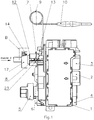
- the in the FIG. 1 illustrated exemplary gas control valve according to the invention is a switching and control device, which is preferably intended for a gas-fired heater or the like. It allows the operation and monitoring of a burner, the pressure control, as well as the adjustment and regulation of the desired temperature by controlling the amount of gas flowing to the burner.
- a valve associated with the switching system via which the gas quantity flowing to the burner is regulated, can be activated by a switch likewise associated with the switching system.
- the switch is a longitudinally movable plunger 7 in non-positive connection. It protrudes from the gas-carrying space of the housing 1 and is supported with its end facing away from the switch to a temperature-sensitive element 8, a metal bellows from.
- the metal bellows 8 is connected via a capillary 9 with a temperature sensor 10.
- Metal bellows 8, capillary 9 and temperature sensor 10 are filled with a thermo-active liquid.
- a tubular locking piece 14 fixed and in particular pressed against rotation.
- the lateral surface of the threaded part 12 is additionally provided in this area with a knurling.
- the pressed-locking piece 14 is supported on the end face of the threaded part 12.
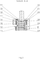
- the collar 15 on its side facing away from the threaded portion 12 an upstanding stop member 16, whose function will be explained in more detail below ( Fig. 3 ).
- a cup-shaped adjusting member 17 is axially mounted on the locking piece 14 so that it includes the locking piece 14 and partially also the threaded piece 12 with its recess 18.
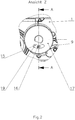
- a breakthrough located in the end face of the adjusting element 17 serves as a guide contour 19 for the stop element 16 (FIG. Fig. 2 ).
- the locking piece 14 has at least partially on its outer cylindrical surface Locking collar 20 which projects into a circumferential locking groove 21 located in the inner wall of the recess 18.
- the adjustment 17 further includes a lock for torsion-proof connection with the threaded part 12 is present. It is formed in this embodiment by two opposite in the lateral surface of the adjusting element 17 screwed screws 22.
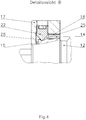
- the locking piece 14 has clearances 25 in these areas in order to produce the desired firm connection between adjusting element 17 and threaded piece 12.
- Necessary stops for limiting the rotational movement of the adjusting element 17 are formed by a rib 23 located on the top 13 of the housing 1 and a partial extension 24 of the lateral surface of the adjusting element 17.
- the adjusting element 17 is rotated within the adjustment range limited by the stops formed by rib 23 and extension 24.
Description
Die Erfindung betrifft eine Gasregelarmatur für ein gasbetriebenes Heizgerät nach dem Oberbegriff des ersten Patentanspruches.The invention relates to a gas control valve for a gas-fired heater according to the preamble of the first claim.
Gasregelarmaturen für gasbetriebene Heizgeräte dienen zur Zündung und zur Steuerung bzw. Regelung eines einem Brenner zufließenden Gasstromes. Dabei muss die Sicherheit für Betreiber und Anlage gewährleistet sein. Als Regelgröße dient dabei üblicherweise eine Temperatur, die durch einen Temperaturfühler erfasst wird, der über eine Kapillarleitung mit einem temperaturempfindlichen Element, beispielsweise ein Metallfaltenbalg als Hubelement, verbunden ist.Gas control valves for gas-fired heaters are used for ignition and for controlling or regulating a gas flow flowing to a burner. At the same time, the safety of the operator and the installation must be guaranteed. As a controlled variable usually serves a temperature that is detected by a temperature sensor, which is connected via a capillary with a temperature-sensitive element, such as a metal bellows as a lifting element.
So ist beispielsweise für den Einbau in Einzelraumheizern aus der
Üblicherweise sind derartige Gasregelarmaturen für einen definierten Sollwertbereich ausgelegt und werden im Rahmen der Fertigung dementsprechend einjustiert. Dies trifft auch auf die in der
Insbesondere in der Küchentechnik wird es jedoch gewünscht, dass die Justierung einfach korrigiert werden kann, wenn es auf Grund einer Anwendung erforderlich ist. Diese nachträgliche Verschiebung des vom Hersteller der Gasregelarmatur vorgegebenen Sollwertbereiches in einem begrenzten Bereich ist jedoch bei allen diesen weiter oben beschriebenen Gasregelarmaturen nicht möglich.However, especially in the kitchen art, it is desired that the adjustment can be easily corrected when required by an application. However, this subsequent shift in the setpoint range specified by the manufacturer of the gas control valve in a limited range is not possible with all of the gas control valves described above.
Der Erfindung liegt das Problem zugrunde eine Gasregelarmatur zu schaffen, bei der eine nachträgliche Verschiebung des vorgegebenen Sollwertbereiches in einfacher Weise vorgenommen werden kann, um den Bereich der einstellbaren Temperatur für das Heizgerät zu optimieren, ohne die geräte- und/oder anlagenspezifischen zugelassenen Einsatzbedingungen zu überschreiten. Dies soll insbesondere ohne Eingriff in den gasführenden Raum ermöglicht werden.The invention is based on the problem to provide a gas control valve, in which a subsequent shift of the predetermined setpoint range can be made in a simple manner to optimize the range of the adjustable temperature for the heater without exceeding the device and / or plant-specific approved conditions of use , This should be made possible in particular without intervention in the gas-carrying space.
Erfindungsgemäß wird das Problem dadurch gelöst, dass ein Einstellelement, das zur Veränderung der Lage eines temperaturempfindlichen Elementes und damit zur Betätigung eines Schalters zur Ansteuerung eines Ventils dient, ein in das Gehäuse der Gasregelarmatur einschraubbares Gewindestück aufweist. Dabei sind beide über eine lösbare Arretierung verdrehsicher miteinander verbunden, wobei zwischen dem das Gewindestück mit einer Ausnehmung teilweise umfassenden topfförmigen Einstellelement und dem Gewindestück ein fest mit dem Gewindestück verbundenes rohrförmiges Raststück angeordnet ist. Mit einem stirnseitig aufragenden Anschlagelement ragt das Raststück in eine Führungskontur hinein, die durch einen im Einstellelement befindlichen stirnseitigen Durchbruch gebildet wird.According to the invention the problem is solved in that an adjusting element which serves to change the position of a temperature-sensitive element and thus to actuate a switch for driving a valve, has a screwed into the housing of the gas control valve threaded piece. Both are connected to each other via a releasable locking against rotation, wherein between the threaded piece with a recess partially comprehensive pot-shaped adjusting element and the threaded piece a fixedly connected to the threaded piece tubular locking piece is arranged. With a frontally upstanding stop element, the locking piece protrudes into a guide contour, which is formed by an opening located in the adjustment frontal breakthrough.
Damit wurde eine Lösung gefunden, mit der es möglich ist, dass der Anwender eine nachträgliche Verschiebung des vom Hersteller der Gasregelarmatur vorgegebenen Sollwertbereiches vornehmen kann. Durch die Führungskontur wird gleichzeitig die Verschiebung des Sollwertbereiches derart begrenzt, dass die geräte- bzw. anlagenspezifisch zugelassenen Einsatzbedingungen nicht überschritten werden können. Dabei zeichnet sich die Lösung durch ihren einfachen Aufbau und ihre einfache Wirkungsweise aus.Thus, a solution was found with which it is possible that the user can make a subsequent shift of the setpoint range specified by the manufacturer of the gas control valve. At the same time, the displacement of the setpoint range is limited by the guide contour in such a way that the operating conditions or plant-specific permitted operating conditions can not be exceeded. The solution is characterized by its simple structure and simple operation.
Eine vorteilhafte Ausgestaltung ergibt sich, wenn das Raststück mit einem auf seiner äußeren zylindrischen Oberfläche zumindest teilweise vorhandenen Rastbund in eine in der Innenwandung der Ausnehmung befindliche umlaufende Rastnut hineinragt.An advantageous embodiment is obtained when the locking piece protrudes with a on its outer cylindrical surface at least partially existing locking collar in a located in the inner wall of the recess circumferential locking groove.
Auf Grund der durch Rastbund und Rastnut entstehenden Verbindung zwischen dem Einstellring und dem Raststück wird in dieser Ausgestaltung zusätzlich sichergestellt, dass ein Verschieben des Sollwertbereiches mit Überschreiten der zugelassenen Einsatzbedingungen, indem durch Demontage das Anschlagelement aus der Führungskontur entfernt wird, nicht zerstörungsfrei möglich ist.Due to the resulting by latching collar and locking groove connection between the adjusting ring and the locking piece is additionally ensured in this embodiment that a displacement of the setpoint range with exceeding the approved conditions of use by removing the stop element from the guide contour is removed by disassembly, non-destructive possible.
Die Erfindung wird nachstehend an einem Ausführungsbeispiel näher beschrieben. Es zeigen:
- Fig. 1
- eine erfindungsgemäße Gasregelarmatur
- Fig. 2
- eine Ansicht Z der erfindungsgemäßen Gasregelarmatur aus
Fig. 1 in vergrößerter Darstellung - Fig. 3
- eine Schnittansicht A - A der erfindungsgemäßen Gasregelarmatur aus
Fig. 1 in vergrößerter Darstellung. - Fig. 4
- eine Detailansicht B der erfindungsgemäßen Gasregelarmatur aus
Fig. 1 in vergrößerter Darstellung.
- Fig. 1
- a gas control valve according to the invention
- Fig. 2
- a view Z of the gas control valve according to the invention from
Fig. 1 in an enlarged view - Fig. 3
- a sectional view A - A of the gas control valve according to the invention from
Fig. 1 in an enlarged view. - Fig. 4
- a detail B of the gas control valve according to the invention from
Fig. 1 in an enlarged view.
Die in der
Die Gasregelarmatur besteht aus einem Gehäuse 1, das einen durch Richtungspfeil gekennzeichneten Gaseingang 2 und einen ebenfalls durch einen Richtungspfeil gekennzeichneten Gasausgang 3, sowie einen Zündgasausgang 4 aufweist. In dem Gehäuse 1 sind in Strömungsrichtung des Gases gesehen, nachfolgende Funktionseinheiten untergebracht:
- Inbetriebnahme mit
dazugehörigem Bedienungselement 5, - Zündsicherungsventil und Hauptventil mit Wiedereinschaltverriegelung,
Druckregler 6,- Schaltsystem eines kombinierten Proportionalreglers/Zweipunktreglers zur Regelung der zum Brenner strömenden Gasmenge.
- Commissioning with associated
operating element 5, - Ignition valve and main valve with reclosing lock,
-
Pressure regulator 6, - Switching system of a combined proportional controller / two-point controller for controlling the amount of gas flowing to the burner.
Aufbau und Wirkungsweise der Inbetriebnahme, des Zündsicherungs- und des Hauptventils, des Druckreglers 6 und des Schaltsystems sind dem Fachmann bekannt. Auf eine nähere Darstellung und Erläuterung der Einzelheiten wird deshalb in diesem Ausführungsbeispiel verzichtet.Design and operation of the commissioning, the Zündsicherungs- and the main valve, the
Ein zum Schaltsystem zugehöriges Ventil, über welches die zum Brenner strömende Gasmenge geregelt wird, ist durch einen ebenfalls zum Schaltsystem zugehörigen Schalter ansteuerbar.A valve associated with the switching system, via which the gas quantity flowing to the burner is regulated, can be activated by a switch likewise associated with the switching system.
Mit dem Schalter steht ein längsbeweglicher Stößel 7 in kraftschlüssiger Verbindung. Er ragt aus dem gasführenden Raum des Gehäuses 1 heraus und stützt sich mit seinem dem Schalter abgewandten Ende an einem temperaturempfindlichen Element 8, einem Metallfaltenbalg, ab. Der Metallfaltenbalg 8 ist über eine Kapillarleitung 9 mit einem Temperaturfühler 10 verbunden. Metallfaltenbalg 8, Kapillarleitung 9 und Temperaturfühler 10 sind mit einer thermoaktiven Flüssigkeit gefüllt.With the switch is a longitudinally
Auf seiner dem Stößel 7 abgewandten Seite stützt sich, in diesem Ausführungsbeispiel günstigerweise über eine dazwischen gelagerte Kugel 11, auf dem Metallfaltenbalg 8 ein Gewindestück 12 ab, das in einem im Inneren eines zum Gehäuse 1 zugehörigen rohrförmigen Aufsatzes 13 befindlichen Gewinde schraubbar geführt ist, um im Rahmen der Fertigung eine Temperaturjustierung vornehmen zu können.On its side facing away from the
Auf dem Gewindestück 12 ist desweiteren ein rohrförmiges Raststück 14 fest und insbesondere verdrehsicher aufgepresst. Dazu ist die Mantelfläche des Gewindestücks 12 in diesem Bereich zusätzlich mit einer Rändelung versehen. Mit einem umlaufenden inneren Bund 15 stützt sich das aufgepresste Raststück 14 auf der Stirnfläche des Gewindestücks 12 ab. Zusätzlich weist der Bund 15 auf seiner dem Gewindestück 12 abgewandten Stirnseite ein aufragendes Anschlagelement 16 auf, dessen Funktion weiter unten näher erläutert wird (
Ein topfförmiges Einstellelement 17 ist axial derart auf das Raststück 14 aufgesetzt, dass es mit seiner Ausnehmung 18 das Raststück 14 und teilweise auch das Gewindestück 12 umfasst. Dabei dient ein in der Stirnfläche des Einstellelementes 17 befindlicher Durchbruch als Führungskontur 19 für das in ihn hineinragende und weiter oben bereits beschriebene Anschlagelement 16 (
Im Einstellelement 17 ist desweiteren eine Arretierung zur verdrehsicheren Verbindung mit dem Gewindestück 12 vorhanden. Sie wird in diesem Ausführungsbeispiel durch zwei gegenüberliegend in die Mantelfläche des Einstellelementes 17 eindrehbare Schrauben 22 gebildet.In the
Es versteht sich dabei von selbst, dass das Raststück 14 in diesen Bereichen Freimachungen 25 aufweist, um die gewünschte feste Verbindung zwischen Einstellelement 17 und Gewindestück 12 herzustellen. Durch, wie in diesem Ausführungsbeispiel erfolgt, die Verwendung von Schrauben 22, die mit einer Spitze versehen sind, und eine im Gewindestück 12 eingebrachte umlaufende Nut 26, in die die Schrauben 22 hineingedreht werden, kann die Verbindung noch sicherer gestaltet werden (
Notwendige Anschläge zur Begrenzung der Drehbewegung des Einstellelementes 17 werden durch eine am Aufsatz 13 des Gehäuses 1 befindliche Rippe 23 und eine teilweise Verlängerung 24 der Mantelfläche des Einstellelementes 17 gebildet.Necessary stops for limiting the rotational movement of the adjusting
Um, wie normalerweise üblich, einen gewünschten Wert der Temperatur aus dem vom Hersteller der Gasregelarmatur vorgegebenen Sollwertbereich einzustellen, wird das Einstellelement 17 innerhalb des durch die Anschläge, gebildet von Rippe 23 und Verlängerung 24, begrenzten Verstellbereiches verdreht.In order, as is customary, to set a desired value of the temperature from the set value range specified by the manufacturer of the gas control fitting, the adjusting
Soll nun durch den Anwender eine nachträgliche Verschiebung des vom Hersteller der Gasregelarmatur vorgegebenen Sollwertbereiches erfolgen, so ist zuerst die Arretierung zwischen Gewindestück 12 und Einstellelement 17 zu lösen. Dann kann das Einstellelement 17 innerhalb des durch die Führungskontur 19 und des Anschlagelementes 16 vorgegebenen Bereiches verdreht werden. Anschließend ist die Arretierung wieder herzustellen.If now carried out by the user a subsequent shift of the setpoint range specified by the manufacturer of the gas control valve, so the lock between the threaded
Eine größere Verschiebung des Sollwertbereiches ist auf Grund der zerstörungsfrei nicht mehr lösbaren Verbindung zwischen Einstellelement 17, Raststück 14 und Gewindestück 12 nicht möglich.A larger shift of the desired value range is not possible due to the non-destructive no longer releasable connection between the adjusting
- 11
- Gehäusecasing
- 22
- Gaseinganggas input
- 33
- Gasausganggas output
- 44
- Zündgasausgangignition gas output
- 55
- Bedienungselementoperating element
- 66
- Druckreglerpressure regulator
- 77
- Stößeltappet
- 88th
- Temperaturempfindliches ElementTemperature-sensitive element
- 99
- Kapillarleitungcapillary
- 1010
- Temperaturfühlertemperature sensor
- 1111
- KugelBullet
- 1212
- Gewindestückthreaded piece
- 1313
- Aufsatzessay
- 1414
- Raststücklocking piece
- 1515
- BundFederation
- 1616
- Anschlagelementstop element
- 1717
- Einstellelementadjustment
- 1818
- Ausnehmungrecess
- 1919
- Führungskonturguide contour
- 2020
- Rastbundlocking collar
- 2121
- Rastnutlocking groove
- 2222
- Schraubescrew
- 2323
- Ripperib
- 2424
- Verlängerungrenewal
- 2525
- Freimachungfranking
- 2626
- Nutgroove
Claims (2)
- Gas regulator fitting for a gas-fired heating device with at least one valve that is arranged downstream of the main valve in the flow path of the gas flow for the main burner, that can be controlled by a switch and that is accommodated in a housing (1) with additional secondary functional elements, wherein the switch can be operated by a longitudinally movable tappet (7) which leads out of the gas-conducting area of the housing (1) and whose position can be altered via a temperature-sensitive element (8), wherein the temperature-sensitive element 8 is supported on a setting element (17) which alters its position and whose operation serving to alter the position of the temperature-sensitive element 8 is restricted by the stops located on the housing (1) and on the setting element (17), that can be operated manually and/or by a drive unit, wherein the setting element (17) has a threaded element (12) that can be screwed into the housing (1) and both are interconnected rigidly via a removable locking device (22), characterized in that a tubular latching part (14) securely connected to the threaded element (12) is arranged between the cup-shaped setting element (17) partly covering the threaded element (12) with a recess (18) and the threaded element (12), and the latching part (14) with a stop element (16) projecting on a front face protrudes into a guide contour (19) formed by an aperture located in the setting element (17) on the front side.
- Gas regulator fitting for a gas-fired heating device according to claim 1, characterized in that the latching part (14) with a locking collar (20) on at least part of its external cylindrical surface protrudes into a circumferential locking groove (21) located in the inner wall of the recess 18).
Priority Applications (2)
| Application Number | Priority Date | Filing Date | Title |
|---|---|---|---|
| SI201430309T SI2976571T1 (en) | 2013-03-18 | 2014-03-17 | Gas control valve |
| PL14716753T PL2976571T3 (en) | 2013-03-18 | 2014-03-17 | Gas control valve |
Applications Claiming Priority (2)
| Application Number | Priority Date | Filing Date | Title |
|---|---|---|---|
| DE102013004745.5A DE102013004745B4 (en) | 2013-03-18 | 2013-03-18 | Gas control valve |
| PCT/EP2014/000718 WO2014146777A1 (en) | 2013-03-18 | 2014-03-17 | Gas control valve |
Publications (2)
| Publication Number | Publication Date |
|---|---|
| EP2976571A1 EP2976571A1 (en) | 2016-01-27 |
| EP2976571B1 true EP2976571B1 (en) | 2017-05-10 |
Family
ID=50478808
Family Applications (1)
| Application Number | Title | Priority Date | Filing Date |
|---|---|---|---|
| EP14716753.0A Active EP2976571B1 (en) | 2013-03-18 | 2014-03-17 | Gas control valve |
Country Status (15)
| Country | Link |
|---|---|
| US (1) | US9696033B2 (en) |
| EP (1) | EP2976571B1 (en) |
| CN (1) | CN105190178B (en) |
| AU (1) | AU2014234683B2 (en) |
| CA (1) | CA2907420A1 (en) |
| DE (1) | DE102013004745B4 (en) |
| DK (1) | DK2976571T3 (en) |
| ES (1) | ES2636841T3 (en) |
| HK (1) | HK1217752A1 (en) |
| HU (1) | HUE033101T2 (en) |
| PL (1) | PL2976571T3 (en) |
| PT (1) | PT2976571T (en) |
| RU (1) | RU2653619C2 (en) |
| SI (1) | SI2976571T1 (en) |
| WO (1) | WO2014146777A1 (en) |
Families Citing this family (2)
| Publication number | Priority date | Publication date | Assignee | Title |
|---|---|---|---|---|
| WO2020094245A1 (en) * | 2018-11-06 | 2020-05-14 | Mertik Maxitrol Gmbh & Co. Kg | Device for regulating a supply of gas |
| CN115013587B (en) * | 2022-08-02 | 2023-01-03 | 浙江轩安居暖通科技有限公司 | Self-operated temperature control valve capable of controlling pressure |
Family Cites Families (11)
| Publication number | Priority date | Publication date | Assignee | Title |
|---|---|---|---|---|
| US2724409A (en) * | 1951-12-29 | 1955-11-22 | Honeywell Regulator Co | Thermostatic valve |
| US2857103A (en) * | 1953-09-04 | 1958-10-21 | Baso Inc | Modulating fuel control apparatus |
| US2783946A (en) | 1953-09-25 | 1957-03-05 | Stewart Warner Corp | Gas modulating and shutoff valve mechanism |
| US2980386A (en) * | 1959-04-30 | 1961-04-18 | Harold C Reinhart | Thermostatic gas valve control |
| DE29902204U1 (en) * | 1999-02-08 | 1999-12-09 | Erhardt Axel | Wall / post and foundation elements |
| DE29905204U1 (en) | 1999-03-22 | 1999-06-10 | Mertik Maxitrol Gmbh & Co Kg | Gas control valve |
| RU2280215C1 (en) * | 2005-01-27 | 2006-07-20 | Евгений Васильевич Бусыгин | Domestic gas flow-type water heater |
| DE102006052296A1 (en) * | 2006-09-04 | 2008-03-06 | Otto Egelhof Gmbh & Co. Kg | Thermostatic valve for controlling a mass flow |
| ITAN20070026A1 (en) * | 2007-04-27 | 2008-10-28 | Merloni Termosanitari Spa | METHOD OF MANAGEMENT OF WATER TEMPERATURE IN WATER HEATER WITH ACCUMULATION |
| DE102009011611B4 (en) * | 2009-03-04 | 2014-02-27 | Mertik Maxitrol Gmbh & Co. Kg | Gas regulating valve |
| DE102009011343B4 (en) * | 2009-03-05 | 2013-11-07 | Neoperl Gmbh | Flow regulator |
-
2013
- 2013-03-18 DE DE102013004745.5A patent/DE102013004745B4/en not_active Expired - Fee Related
-
2014
- 2014-03-17 AU AU2014234683A patent/AU2014234683B2/en active Active
- 2014-03-17 RU RU2015140470A patent/RU2653619C2/en active
- 2014-03-17 CN CN201480016655.6A patent/CN105190178B/en active Active
- 2014-03-17 DK DK14716753.0T patent/DK2976571T3/en active
- 2014-03-17 CA CA2907420A patent/CA2907420A1/en not_active Abandoned
- 2014-03-17 PT PT147167530T patent/PT2976571T/en unknown
- 2014-03-17 US US14/778,349 patent/US9696033B2/en active Active
- 2014-03-17 HU HUE14716753A patent/HUE033101T2/en unknown
- 2014-03-17 PL PL14716753T patent/PL2976571T3/en unknown
- 2014-03-17 ES ES14716753.0T patent/ES2636841T3/en active Active
- 2014-03-17 WO PCT/EP2014/000718 patent/WO2014146777A1/en active Application Filing
- 2014-03-17 SI SI201430309T patent/SI2976571T1/en unknown
- 2014-03-17 EP EP14716753.0A patent/EP2976571B1/en active Active
-
2016
- 2016-05-17 HK HK16105661.9A patent/HK1217752A1/en unknown
Also Published As
| Publication number | Publication date |
|---|---|
| AU2014234683A1 (en) | 2015-10-22 |
| WO2014146777A1 (en) | 2014-09-25 |
| PL2976571T3 (en) | 2017-10-31 |
| HK1217752A1 (en) | 2017-01-20 |
| ES2636841T3 (en) | 2017-10-09 |
| CN105190178B (en) | 2017-03-15 |
| DE102013004745A1 (en) | 2014-09-18 |
| DK2976571T3 (en) | 2017-09-04 |
| US20160069565A1 (en) | 2016-03-10 |
| PT2976571T (en) | 2017-08-09 |
| RU2653619C2 (en) | 2018-05-11 |
| CA2907420A1 (en) | 2014-09-25 |
| US9696033B2 (en) | 2017-07-04 |
| CN105190178A (en) | 2015-12-23 |
| SI2976571T1 (en) | 2017-08-31 |
| AU2014234683B2 (en) | 2016-05-05 |
| DE102013004745B4 (en) | 2020-03-05 |
| HUE033101T2 (en) | 2017-11-28 |
| RU2015140470A (en) | 2017-04-27 |
| EP2976571A1 (en) | 2016-01-27 |
Similar Documents
| Publication | Publication Date | Title |
|---|---|---|
| EP2271969B1 (en) | Valve combination for regulating the flow rate or differential pressure | |
| EP1275039B1 (en) | Gas pressure regulator | |
| EP2887170B1 (en) | Thermostatic mixer valve | |
| EP1614975A2 (en) | Air flow controller, in particular for ventilation and/or air-conditioning devices | |
| EP2976571B1 (en) | Gas control valve | |
| EP2404113B1 (en) | Gas regulator fitting | |
| EP3149406B1 (en) | Gas control valve, hob and gas oven | |
| DE102007013505A1 (en) | Armature combination for use in liquid-containing heating or cooling system, has flow cross-section adjusted with actuator by handle, where state of handle is read on indicator that indicates pre-adjustment of flow cross-section | |
| DE102013218014B4 (en) | Gas valve device and gas appliance with a gas valve device | |
| DE102012003912B3 (en) | Fitting for a continuous flow water heater | |
| DE10303828B4 (en) | thermostatic valve | |
| DE944225C (en) | Temperature regulator for gas ovens, gas heaters and like | |
| DE2312305C2 (en) | Device for influencing the performance of a gas-heated instantaneous water heater | |
| WO2000057107A1 (en) | Gas regulating fixture | |
| DE4427846A1 (en) | Control device for the temperature of the water taken from a water pipe | |
| DE2518443A1 (en) | Thermostat for screwing to heater valve - has expanding bellows pushing against pressure plug with adjustable screw cap | |
| EP1903415B1 (en) | Device for flow limitation | |
| DE102018001539B4 (en) | Device for displaying the status of a gas burner | |
| EP2504743B1 (en) | Return flow temperature control valve for cooling systems | |
| DE701621C (en) | Device for automatic regulation of the room air temperature | |
| DE1529100C3 (en) | Control valve for regulating the supply of a flammable fluid | |
| DE1529055B1 (en) | Standard fitting for a gas-heated device consisting of an oven and grill | |
| DE7329274U (en) | Top-mounted thermostat for valves | |
| WO2009026901A2 (en) | Temperature regulating arrangement | |
| DE1254556B (en) | Temperature regulator for gas-heated devices |
Legal Events
| Date | Code | Title | Description |
|---|---|---|---|
| PUAI | Public reference made under article 153(3) epc to a published international application that has entered the european phase |
Free format text: ORIGINAL CODE: 0009012 |
|
| 17P | Request for examination filed |
Effective date: 20150901 |
|
| AK | Designated contracting states |
Kind code of ref document: A1 Designated state(s): AL AT BE BG CH CY CZ DE DK EE ES FI FR GB GR HR HU IE IS IT LI LT LU LV MC MK MT NL NO PL PT RO RS SE SI SK SM TR |
|
| AX | Request for extension of the european patent |
Extension state: BA ME |
|
| DAX | Request for extension of the european patent (deleted) | ||
| GRAP | Despatch of communication of intention to grant a patent |
Free format text: ORIGINAL CODE: EPIDOSNIGR1 |
|
| RIC1 | Information provided on ipc code assigned before grant |
Ipc: G05D 7/06 20060101ALI20161205BHEP Ipc: F23N 5/02 20060101AFI20161205BHEP Ipc: F23N 1/00 20060101ALI20161205BHEP Ipc: F16L 15/08 20060101ALI20161205BHEP Ipc: G05D 23/01 20060101ALI20161205BHEP Ipc: F23N 5/06 20060101ALI20161205BHEP Ipc: F16K 31/00 20060101ALI20161205BHEP |
|
| INTG | Intention to grant announced |
Effective date: 20161221 |
|
| GRAS | Grant fee paid |
Free format text: ORIGINAL CODE: EPIDOSNIGR3 |
|
| GRAA | (expected) grant |
Free format text: ORIGINAL CODE: 0009210 |
|
| AK | Designated contracting states |
Kind code of ref document: B1 Designated state(s): AL AT BE BG CH CY CZ DE DK EE ES FI FR GB GR HR HU IE IS IT LI LT LU LV MC MK MT NL NO PL PT RO RS SE SI SK SM TR |
|
| REG | Reference to a national code |
Ref country code: GB Ref legal event code: FG4D Free format text: NOT ENGLISH |
|
| REG | Reference to a national code |
Ref country code: AT Ref legal event code: REF Ref document number: 892762 Country of ref document: AT Kind code of ref document: T Effective date: 20170515 Ref country code: CH Ref legal event code: EP |
|
| REG | Reference to a national code |
Ref country code: IE Ref legal event code: FG4D Free format text: LANGUAGE OF EP DOCUMENT: GERMAN |
|
| REG | Reference to a national code |
Ref country code: DE Ref legal event code: R096 Ref document number: 502014003798 Country of ref document: DE |
|
| REG | Reference to a national code |
Ref country code: RO Ref legal event code: EPE |
|
| REG | Reference to a national code |
Ref country code: PT Ref legal event code: SC4A Ref document number: 2976571 Country of ref document: PT Date of ref document: 20170809 Kind code of ref document: T Free format text: AVAILABILITY OF NATIONAL TRANSLATION Effective date: 20170801 |
|
| REG | Reference to a national code |
Ref country code: NL Ref legal event code: FP |
|
| REG | Reference to a national code |
Ref country code: SE Ref legal event code: TRGR |
|
| REG | Reference to a national code |
Ref country code: DK Ref legal event code: T3 Effective date: 20170829 |
|
| REG | Reference to a national code |
Ref country code: LT Ref legal event code: MG4D |
|
| REG | Reference to a national code |
Ref country code: ES Ref legal event code: FG2A Ref document number: 2636841 Country of ref document: ES Kind code of ref document: T3 Effective date: 20171009 |
|
| PG25 | Lapsed in a contracting state [announced via postgrant information from national office to epo] |
Ref country code: NO Free format text: LAPSE BECAUSE OF FAILURE TO SUBMIT A TRANSLATION OF THE DESCRIPTION OR TO PAY THE FEE WITHIN THE PRESCRIBED TIME-LIMIT Effective date: 20170810 Ref country code: FI Free format text: LAPSE BECAUSE OF FAILURE TO SUBMIT A TRANSLATION OF THE DESCRIPTION OR TO PAY THE FEE WITHIN THE PRESCRIBED TIME-LIMIT Effective date: 20170510 Ref country code: HR Free format text: LAPSE BECAUSE OF FAILURE TO SUBMIT A TRANSLATION OF THE DESCRIPTION OR TO PAY THE FEE WITHIN THE PRESCRIBED TIME-LIMIT Effective date: 20170510 Ref country code: LT Free format text: LAPSE BECAUSE OF FAILURE TO SUBMIT A TRANSLATION OF THE DESCRIPTION OR TO PAY THE FEE WITHIN THE PRESCRIBED TIME-LIMIT Effective date: 20170510 |
|
| REG | Reference to a national code |
Ref country code: GR Ref legal event code: EP Ref document number: 20170401930 Country of ref document: GR Effective date: 20171122 |
|
| REG | Reference to a national code |
Ref country code: HU Ref legal event code: AG4A Ref document number: E033101 Country of ref document: HU |
|
| PG25 | Lapsed in a contracting state [announced via postgrant information from national office to epo] |
Ref country code: LV Free format text: LAPSE BECAUSE OF FAILURE TO SUBMIT A TRANSLATION OF THE DESCRIPTION OR TO PAY THE FEE WITHIN THE PRESCRIBED TIME-LIMIT Effective date: 20170510 Ref country code: BG Free format text: LAPSE BECAUSE OF FAILURE TO SUBMIT A TRANSLATION OF THE DESCRIPTION OR TO PAY THE FEE WITHIN THE PRESCRIBED TIME-LIMIT Effective date: 20170810 Ref country code: RS Free format text: LAPSE BECAUSE OF FAILURE TO SUBMIT A TRANSLATION OF THE DESCRIPTION OR TO PAY THE FEE WITHIN THE PRESCRIBED TIME-LIMIT Effective date: 20170510 Ref country code: IS Free format text: LAPSE BECAUSE OF FAILURE TO SUBMIT A TRANSLATION OF THE DESCRIPTION OR TO PAY THE FEE WITHIN THE PRESCRIBED TIME-LIMIT Effective date: 20170910 |
|
| PG25 | Lapsed in a contracting state [announced via postgrant information from national office to epo] |
Ref country code: SK Free format text: LAPSE BECAUSE OF FAILURE TO SUBMIT A TRANSLATION OF THE DESCRIPTION OR TO PAY THE FEE WITHIN THE PRESCRIBED TIME-LIMIT Effective date: 20170510 Ref country code: EE Free format text: LAPSE BECAUSE OF FAILURE TO SUBMIT A TRANSLATION OF THE DESCRIPTION OR TO PAY THE FEE WITHIN THE PRESCRIBED TIME-LIMIT Effective date: 20170510 Ref country code: CZ Free format text: LAPSE BECAUSE OF FAILURE TO SUBMIT A TRANSLATION OF THE DESCRIPTION OR TO PAY THE FEE WITHIN THE PRESCRIBED TIME-LIMIT Effective date: 20170510 |
|
| REG | Reference to a national code |
Ref country code: DE Ref legal event code: R097 Ref document number: 502014003798 Country of ref document: DE |
|
| REG | Reference to a national code |
Ref country code: FR Ref legal event code: PLFP Year of fee payment: 5 |
|
| PG25 | Lapsed in a contracting state [announced via postgrant information from national office to epo] |
Ref country code: SM Free format text: LAPSE BECAUSE OF FAILURE TO SUBMIT A TRANSLATION OF THE DESCRIPTION OR TO PAY THE FEE WITHIN THE PRESCRIBED TIME-LIMIT Effective date: 20170510 |
|
| PLBE | No opposition filed within time limit |
Free format text: ORIGINAL CODE: 0009261 |
|
| STAA | Information on the status of an ep patent application or granted ep patent |
Free format text: STATUS: NO OPPOSITION FILED WITHIN TIME LIMIT |
|
| 26N | No opposition filed |
Effective date: 20180213 |
|
| PGFP | Annual fee paid to national office [announced via postgrant information from national office to epo] |
Ref country code: RO Payment date: 20180212 Year of fee payment: 5 Ref country code: DK Payment date: 20180319 Year of fee payment: 5 |
|
| PGFP | Annual fee paid to national office [announced via postgrant information from national office to epo] |
Ref country code: SI Payment date: 20180206 Year of fee payment: 5 Ref country code: HU Payment date: 20180214 Year of fee payment: 5 Ref country code: SE Payment date: 20180208 Year of fee payment: 5 |
|
| PG25 | Lapsed in a contracting state [announced via postgrant information from national office to epo] |
Ref country code: MT Free format text: LAPSE BECAUSE OF FAILURE TO SUBMIT A TRANSLATION OF THE DESCRIPTION OR TO PAY THE FEE WITHIN THE PRESCRIBED TIME-LIMIT Effective date: 20170510 |
|
| REG | Reference to a national code |
Ref country code: CH Ref legal event code: PL |
|
| PG25 | Lapsed in a contracting state [announced via postgrant information from national office to epo] |
Ref country code: MC Free format text: LAPSE BECAUSE OF FAILURE TO SUBMIT A TRANSLATION OF THE DESCRIPTION OR TO PAY THE FEE WITHIN THE PRESCRIBED TIME-LIMIT Effective date: 20170510 |
|
| REG | Reference to a national code |
Ref country code: IE Ref legal event code: MM4A |
|
| PG25 | Lapsed in a contracting state [announced via postgrant information from national office to epo] |
Ref country code: LU Free format text: LAPSE BECAUSE OF NON-PAYMENT OF DUE FEES Effective date: 20180317 |
|
| PG25 | Lapsed in a contracting state [announced via postgrant information from national office to epo] |
Ref country code: IE Free format text: LAPSE BECAUSE OF NON-PAYMENT OF DUE FEES Effective date: 20180317 Ref country code: GR Free format text: LAPSE BECAUSE OF NON-PAYMENT OF DUE FEES Effective date: 20181003 |
|
| PG25 | Lapsed in a contracting state [announced via postgrant information from national office to epo] |
Ref country code: CH Free format text: LAPSE BECAUSE OF NON-PAYMENT OF DUE FEES Effective date: 20180331 Ref country code: LI Free format text: LAPSE BECAUSE OF NON-PAYMENT OF DUE FEES Effective date: 20180331 |
|
| REG | Reference to a national code |
Ref country code: DK Ref legal event code: EBP Effective date: 20190331 |
|
| REG | Reference to a national code |
Ref country code: SE Ref legal event code: EUG |
|
| PG25 | Lapsed in a contracting state [announced via postgrant information from national office to epo] |
Ref country code: RO Free format text: LAPSE BECAUSE OF NON-PAYMENT OF DUE FEES Effective date: 20190317 Ref country code: SE Free format text: LAPSE BECAUSE OF NON-PAYMENT OF DUE FEES Effective date: 20190318 |
|
| REG | Reference to a national code |
Ref country code: SI Ref legal event code: KO00 Effective date: 20191111 |
|
| PG25 | Lapsed in a contracting state [announced via postgrant information from national office to epo] |
Ref country code: HU Free format text: LAPSE BECAUSE OF NON-PAYMENT OF DUE FEES Effective date: 20190318 |
|
| PG25 | Lapsed in a contracting state [announced via postgrant information from national office to epo] |
Ref country code: SI Free format text: LAPSE BECAUSE OF NON-PAYMENT OF DUE FEES Effective date: 20190318 |
|
| PG25 | Lapsed in a contracting state [announced via postgrant information from national office to epo] |
Ref country code: DK Free format text: LAPSE BECAUSE OF NON-PAYMENT OF DUE FEES Effective date: 20190331 |
|
| PG25 | Lapsed in a contracting state [announced via postgrant information from national office to epo] |
Ref country code: MK Free format text: LAPSE BECAUSE OF NON-PAYMENT OF DUE FEES Effective date: 20170510 Ref country code: CY Free format text: LAPSE BECAUSE OF FAILURE TO SUBMIT A TRANSLATION OF THE DESCRIPTION OR TO PAY THE FEE WITHIN THE PRESCRIBED TIME-LIMIT Effective date: 20170510 |
|
| PG25 | Lapsed in a contracting state [announced via postgrant information from national office to epo] |
Ref country code: AL Free format text: LAPSE BECAUSE OF FAILURE TO SUBMIT A TRANSLATION OF THE DESCRIPTION OR TO PAY THE FEE WITHIN THE PRESCRIBED TIME-LIMIT Effective date: 20170510 |
|
| REG | Reference to a national code |
Ref country code: AT Ref legal event code: MM01 Ref document number: 892762 Country of ref document: AT Kind code of ref document: T Effective date: 20190317 |
|
| PG25 | Lapsed in a contracting state [announced via postgrant information from national office to epo] |
Ref country code: PT Free format text: LAPSE BECAUSE OF NON-PAYMENT OF DUE FEES Effective date: 20200917 |
|
| PG25 | Lapsed in a contracting state [announced via postgrant information from national office to epo] |
Ref country code: AT Free format text: LAPSE BECAUSE OF NON-PAYMENT OF DUE FEES Effective date: 20190317 |
|
| REG | Reference to a national code |
Ref country code: BE Ref legal event code: MM Effective date: 20200331 |
|
| REG | Reference to a national code |
Ref country code: DE Ref legal event code: R081 Ref document number: 502014003798 Country of ref document: DE Owner name: MAXITROL GMBH & CO. KG, DE Free format text: FORMER OWNER: MERTIK MAXITROL GMBH & CO. KG, 06502 THALE, DE |
|
| PG25 | Lapsed in a contracting state [announced via postgrant information from national office to epo] |
Ref country code: BE Free format text: LAPSE BECAUSE OF NON-PAYMENT OF DUE FEES Effective date: 20200331 |
|
| REG | Reference to a national code |
Ref country code: ES Ref legal event code: PC2A Owner name: MAXITROL GMBH & CO. KG Effective date: 20210315 |
|
| REG | Reference to a national code |
Ref country code: NL Ref legal event code: HC Owner name: MAXITROL GMBH & CO. KG; DE Free format text: DETAILS ASSIGNMENT: CHANGE OF OWNER(S), CHANGE OF OWNER(S) NAME; FORMER OWNER NAME: MERTIK MAXITROL GMBH & CO. KG Effective date: 20210312 |
|
| PGFP | Annual fee paid to national office [announced via postgrant information from national office to epo] |
Ref country code: NL Payment date: 20230221 Year of fee payment: 10 |
|
| PGFP | Annual fee paid to national office [announced via postgrant information from national office to epo] |
Ref country code: FR Payment date: 20230228 Year of fee payment: 10 |
|
| PGFP | Annual fee paid to national office [announced via postgrant information from national office to epo] |
Ref country code: TR Payment date: 20230215 Year of fee payment: 10 Ref country code: PL Payment date: 20230209 Year of fee payment: 10 Ref country code: IT Payment date: 20230327 Year of fee payment: 10 Ref country code: GB Payment date: 20230221 Year of fee payment: 10 Ref country code: DE Payment date: 20230228 Year of fee payment: 10 |
|
| PGFP | Annual fee paid to national office [announced via postgrant information from national office to epo] |
Ref country code: ES Payment date: 20230411 Year of fee payment: 10 |
|
| PGFP | Annual fee paid to national office [announced via postgrant information from national office to epo] |
Ref country code: NL Payment date: 20240220 Year of fee payment: 11 |