EP2976186B1 - Module placement device and method - Google Patents
Module placement device and method Download PDFInfo
- Publication number
- EP2976186B1 EP2976186B1 EP14770349.0A EP14770349A EP2976186B1 EP 2976186 B1 EP2976186 B1 EP 2976186B1 EP 14770349 A EP14770349 A EP 14770349A EP 2976186 B1 EP2976186 B1 EP 2976186B1
- Authority
- EP
- European Patent Office
- Prior art keywords
- module
- mirror substrate
- axis
- fixture
- substrate
- Prior art date
- Legal status (The legal status is an assumption and is not a legal conclusion. Google has not performed a legal analysis and makes no representation as to the accuracy of the status listed.)
- Active
Links
- 238000000034 method Methods 0.000 title claims description 17
- 239000000758 substrate Substances 0.000 claims description 70
- 239000000853 adhesive Substances 0.000 claims description 6
- 230000001070 adhesive effect Effects 0.000 claims description 6
- 238000003825 pressing Methods 0.000 claims description 3
- 230000000007 visual effect Effects 0.000 claims 2
- 230000001681 protective effect Effects 0.000 description 4
- 238000004519 manufacturing process Methods 0.000 description 3
- 238000002679 ablation Methods 0.000 description 2
- 238000001514 detection method Methods 0.000 description 1
- 230000000694 effects Effects 0.000 description 1
- 230000006870 function Effects 0.000 description 1
- 238000003384 imaging method Methods 0.000 description 1
- 238000012986 modification Methods 0.000 description 1
- 230000004048 modification Effects 0.000 description 1
- 230000003287 optical effect Effects 0.000 description 1
Images


Classifications
-
- H—ELECTRICITY
- H05—ELECTRIC TECHNIQUES NOT OTHERWISE PROVIDED FOR
- H05K—PRINTED CIRCUITS; CASINGS OR CONSTRUCTIONAL DETAILS OF ELECTRIC APPARATUS; MANUFACTURE OF ASSEMBLAGES OF ELECTRICAL COMPONENTS
- H05K3/00—Apparatus or processes for manufacturing printed circuits
- H05K3/0008—Apparatus or processes for manufacturing printed circuits for aligning or positioning of tools relative to the circuit board
-
- G—PHYSICS
- G05—CONTROLLING; REGULATING
- G05B—CONTROL OR REGULATING SYSTEMS IN GENERAL; FUNCTIONAL ELEMENTS OF SUCH SYSTEMS; MONITORING OR TESTING ARRANGEMENTS FOR SUCH SYSTEMS OR ELEMENTS
- G05B19/00—Programme-control systems
- G05B19/02—Programme-control systems electric
- G05B19/418—Total factory control, i.e. centrally controlling a plurality of machines, e.g. direct or distributed numerical control [DNC], flexible manufacturing systems [FMS], integrated manufacturing systems [IMS], computer integrated manufacturing [CIM]
- G05B19/41805—Total factory control, i.e. centrally controlling a plurality of machines, e.g. direct or distributed numerical control [DNC], flexible manufacturing systems [FMS], integrated manufacturing systems [IMS], computer integrated manufacturing [CIM] characterised by assembly
-
- H—ELECTRICITY
- H05—ELECTRIC TECHNIQUES NOT OTHERWISE PROVIDED FOR
- H05K—PRINTED CIRCUITS; CASINGS OR CONSTRUCTIONAL DETAILS OF ELECTRIC APPARATUS; MANUFACTURE OF ASSEMBLAGES OF ELECTRICAL COMPONENTS
- H05K1/00—Printed circuits
- H05K1/02—Details
- H05K1/0266—Marks, test patterns or identification means
- H05K1/0269—Marks, test patterns or identification means for visual or optical inspection
-
- H—ELECTRICITY
- H05—ELECTRIC TECHNIQUES NOT OTHERWISE PROVIDED FOR
- H05K—PRINTED CIRCUITS; CASINGS OR CONSTRUCTIONAL DETAILS OF ELECTRIC APPARATUS; MANUFACTURE OF ASSEMBLAGES OF ELECTRICAL COMPONENTS
- H05K2201/00—Indexing scheme relating to printed circuits covered by H05K1/00
- H05K2201/09—Shape and layout
- H05K2201/09818—Shape or layout details not covered by a single group of H05K2201/09009 - H05K2201/09809
- H05K2201/09918—Optically detected marks used for aligning tool relative to the PCB, e.g. for mounting of components
-
- Y—GENERAL TAGGING OF NEW TECHNOLOGICAL DEVELOPMENTS; GENERAL TAGGING OF CROSS-SECTIONAL TECHNOLOGIES SPANNING OVER SEVERAL SECTIONS OF THE IPC; TECHNICAL SUBJECTS COVERED BY FORMER USPC CROSS-REFERENCE ART COLLECTIONS [XRACs] AND DIGESTS
- Y02—TECHNOLOGIES OR APPLICATIONS FOR MITIGATION OR ADAPTATION AGAINST CLIMATE CHANGE
- Y02P—CLIMATE CHANGE MITIGATION TECHNOLOGIES IN THE PRODUCTION OR PROCESSING OF GOODS
- Y02P90/00—Enabling technologies with a potential contribution to greenhouse gas [GHG] emissions mitigation
- Y02P90/02—Total factory control, e.g. smart factories, flexible manufacturing systems [FMS] or integrated manufacturing systems [IMS]
Definitions
- the present invention relates generally to the field of precision automated manufacturing. More particularly, the present invention relates to a device and method for automatically placing a module on the underside of an object using optical cues to align the module to the object.
- a rear view mirror might include icons indicative of direction, vehicle functions such as telephone use, and other information and a side view mirror may warn a driver that the turn signal is activated or the side view mirror may be connected to a blind spot detection system so that the driver can be warned about a vehicle in the blind spot.
- a number of techniques have been developed.
- One common technique is to use fine ablations of the reflective surface so that light can pass therethrough but a substantial portion of the reflective surface remains intact.
- the light behind the mirror for the icon is activated it passes through the ablation and can be seen and when the light is not activated the mirror effect remains substantially intact.
- modules Certain automotive manufactures desire highly detailed icons to appear in the mirrors, with a high degree of light, and minimal affect on normal mirror operation. To achieve these requirements, mirror manufacturers have found it necessary to precisely align highly-engineered reflectors and light sources (these highly-engineered reflectors and light sources are referred to herein as "modules") behind finely ablated mirrors. Traditionally, these modules have been positioned against the mirror backs by hand but in the manufacturing process this can lead to an unacceptably high level of rejected parts due to failure to meet performance objectives. As such, there is a need for a high-precision device and method to mate a module to a mirror substrate.
- US6167607 B1 discloses an apparatus for assembling, handling, and fabrication in which targets are used on objects.
- One or more robots and imaging devices for the targets are used.
- the robots can be used to handle or assemble a part, or a fixture may be used in conjunction with the robots.
- a CAD design system is used in designing the targets as well as for the assembly process using the targets.
- the present invention relates to a device and method to precisely mate a highly-engineered light source and reflector module to the rear of a mirror substrate.
- the device and method include the ability to place the module and substrate into fixtures, reposition at least one of the module and the substrate, and then press the two together so that the module adheres to the rear of the substrate.
- the device and method could have other applications where similar performance characteristics are desirable.
- FIGS. 1-3 and 5-13 show one embodiment of a module placement device 100 in accordance with the invention.
- the module placement device 100 stands on a base 102 and has a protective housing 104.
- the protective housing 104 includes safety provisions to prevent unintended operation of the module placement device 100 while an operator's hand is near the device. Such safety provisions may include light curtains, emergency stop switches, two hand controls, mechanical guards, or any other suitable means without departing from the invention.
- Near the module placement device 100 is an operator interface 106 that allows an operator to configure and monitor operation of the module placement device.
- the operator interface 106 is a touch screen attached to the protective housing 104, but any other user interface may be used without departing from the invention.
- the user interface may include but are not limited to a computer with keyboard and mouse, or may be replaced by a programmable logic controller or equivalent.
- the module placement device includes a module fixture 110, and a substrate fixture 112.
- the substrate fixture 112 is for the placement of a blind spot monitor alert light on a side view car mirror, but any suitable substrate may be used without departing from the invention.
- the module fixture 110 is attached to a plurality of actuators and motors that move the module fixture during the module placement process.
- the substrate fixture 112, on the other hand, remains stationary throughout the module placement process. Of course, the module fixture 110 could remain stationary while the substrate fixture 112 moves without departing from the invention.
- a substrate clamp arm 114 is located near the substrate fixture 112 that secures a substrate 116 to the substrate fixture during the module placement process.
- a camera 118 is positioned above the module fixture 110.
- the operator interface 106, module fixture 110, and camera 118 are connected to a controller that controls the operation of the module placement device 100.
- the controller includes a processor, memory, and program that moves the module fixture 110 based on images captured by the camera 118.
- a program is loaded into the controller based on the geometry of the substrate and the module being placed.
- FIG. 4 is a flowchart showing a typical module placement cycle.
- FIGS. 5-11 show the module placement device 100 in various stages of the module placement cycle.
- the module placement device 100 works by visually identifying landmarks on the substrate 116 and a module 118 to automatically and precisely align the substrate and module together.
- the module 118 has an adhesive face that permanently bonds to the substrate 116 when the module is pressed onto it.
- the module 118 could be non-adhesive, with adhesive on the substrate 116 without departing from the invention.
- an operator places a module 118 in the module fixture 110.
- FIG. 5 shows the movement of the module fixture 110 into a position beneath the camera 118.
- the module fixture 110 raises to the height of the substrate 116.
- the camera 118 is focused on both the substrate 116 and the module 118 and the controller, based on the image captured by the camera when the module fixture is raised to the height of the substrate 116, calculates the position of the module relative to the substrate.
- the controller recognizes landmarks on the module 118 and the substrate 116 and uses software to calculate how to align them to each other. Multiple cameras could be used without departing from the invention.
- the controller moves the module fixture 110 back to a descended position so it can move beneath the substrate.
- the controller moves the module fixture 110 based on the calculation described above so that the module 118 is properly aligned with the substrate 116.
- FIG. 8 shows the movement of the module fixture 110 into position beneath the substrate 116.
- FIGS. 9-11 show how the module 118 is placed on the substrate 116.
- the module fixture 110 is positioned beneath the substrate and in position to be affixed to the substrate.
- FIG. 10 shows the module fixture 110 raised so that the module 118 is pressed onto the substrate 116.
- FIG. 11 shows the module fixture 110 descending back to its position in FIG. 9 , with the module 118 affixed to the substrate 116.
- the substrate clamp arm 114 raises and swings away, allowing the operator to remove the now completed part 120 ( FIG. 12 ).
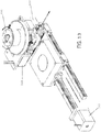
- FIG. 13 shows the module fixture 110 in greater detail.
- the module fixture is movable in four directions.
- the module fixture 110 is movable in the X, Y, and Z axes, as well as a rotational axis around the Z axis. Providing four axes of available movement allows the module 118 to be precisely placed on the substrate 116.
- three stepper motors 122 and a linear actuator control the movement of the module fixture 110.
- the stepper motors 122 control X, Y, and rotational position, and the linear actuator controls the position of the module fixture 110 along the Z axis.
- Using stepper motors 122 allows precision control of the position of the module fixture 110, but any other suitable means may be used without departing from the invention.
Description
- The present invention relates generally to the field of precision automated manufacturing. More particularly, the present invention relates to a device and method for automatically placing a module on the underside of an object using optical cues to align the module to the object.
- Modern automotive mirrors are being called upon to provide more than just a reflective surface for viewing next to or behind the vehicle. In many cases it is desirable to provide the driver with information using the mirror surface but enable the complete mirror surface to be reflective when the information is not being provided. For example, a rear view mirror might include icons indicative of direction, vehicle functions such as telephone use, and other information and a side view mirror may warn a driver that the turn signal is activated or the side view mirror may be connected to a blind spot detection system so that the driver can be warned about a vehicle in the blind spot. In order to achieve a usable mirror surface when the icons are not activated, a number of techniques have been developed. One common technique is to use fine ablations of the reflective surface so that light can pass therethrough but a substantial portion of the reflective surface remains intact. When the light behind the mirror for the icon is activated it passes through the ablation and can be seen and when the light is not activated the mirror effect remains substantially intact.
- Certain automotive manufactures desire highly detailed icons to appear in the mirrors, with a high degree of light, and minimal affect on normal mirror operation. To achieve these requirements, mirror manufacturers have found it necessary to precisely align highly-engineered reflectors and light sources (these highly-engineered reflectors and light sources are referred to herein as "modules") behind finely ablated mirrors. Traditionally, these modules have been positioned against the mirror backs by hand but in the manufacturing process this can lead to an unacceptably high level of rejected parts due to failure to meet performance objectives. As such, there is a need for a high-precision device and method to mate a module to a mirror substrate.
-
US6167607 B1 discloses an apparatus for assembling, handling, and fabrication in which targets are used on objects. One or more robots and imaging devices for the targets are used. The robots can be used to handle or assemble a part, or a fixture may be used in conjunction with the robots. A CAD design system is used in designing the targets as well as for the assembly process using the targets. - The present invention relates to a device and method to precisely mate a highly-engineered light source and reflector module to the rear of a mirror substrate. The device and method include the ability to place the module and substrate into fixtures, reposition at least one of the module and the substrate, and then press the two together so that the module adheres to the rear of the substrate. The device and method could have other applications where similar performance characteristics are desirable.
- It will be understood by those skilled in the art that one or more aspects of this invention can meet certain objectives, while one or more other aspects can lead to certain other objectives. Other objects, features, benefits and advantages of the present invention will be apparent in this summary and descriptions of the disclosed embodiment, and will be readily apparent to those skilled in the art. Such objects, features, benefits and advantages will be apparent from the above as taken in conjunction with the accompanying figures and all reasonable inferences to be drawn therefrom.
-
-
FIG. 1 is a perspective view of one embodiment of a module placement device in accordance with the invention; -
FIG. 2 is another perspective view of the module placement device ofFIG. 1 with the protective housing removed; -
FIG. 3 is a detail view of the module placement device ofFIG. 1 showing the vertical movement of the substrate clamp arm; -
FIG. 4 is a flow chart depicting an operation sequence of a device and method in accordance with one embodiment of the invention; -
FIG. 5 is another detail view of the module placement device ofFIG. 1 showing the initial horizontal movement of the module fixture; -
FIG. 6 is another detail view of the module placement device ofFIG. 1 showing the calibrating vertical movement of the module fixture; -
FIG. 7 is another detail view of the module placement device ofFIG. 1 showing the lowering of the module fixture before placement of the module; -
FIG. 8 is another detail view of the module placement device ofFIG. 1 showing the movement of the module fixture into placement position; -
FIGS. 9-11 are side section views of the module placement device ofFIG. 1 taken generally along the line 8-8 inFIG. 7 showing placement of the module onto the substrate; -
FIG. 12 is another detail view of the module placement device ofFIG. 1 showing removal of the substrate with the module attached; and -
FIG. 13 is another detail view of the module placement device ofFIG. 1 showing the degrees of movement of the module fixture. -
FIGS. 1-3 and5-13 show one embodiment of amodule placement device 100 in accordance with the invention. Themodule placement device 100 stands on abase 102 and has aprotective housing 104. In the embodiment shown, theprotective housing 104 includes safety provisions to prevent unintended operation of themodule placement device 100 while an operator's hand is near the device. Such safety provisions may include light curtains, emergency stop switches, two hand controls, mechanical guards, or any other suitable means without departing from the invention. Near themodule placement device 100 is anoperator interface 106 that allows an operator to configure and monitor operation of the module placement device. In the embodiment shown, theoperator interface 106 is a touch screen attached to theprotective housing 104, but any other user interface may be used without departing from the invention. Alternatively, the user interface may include but are not limited to a computer with keyboard and mouse, or may be replaced by a programmable logic controller or equivalent. - Turning now to
FIG. 2 , a detail view of themodule placement device 100 is shown. The module placement device includes amodule fixture 110, and asubstrate fixture 112. In the embodiment shown, thesubstrate fixture 112 is for the placement of a blind spot monitor alert light on a side view car mirror, but any suitable substrate may be used without departing from the invention. Themodule fixture 110 is attached to a plurality of actuators and motors that move the module fixture during the module placement process. Thesubstrate fixture 112, on the other hand, remains stationary throughout the module placement process. Of course, themodule fixture 110 could remain stationary while thesubstrate fixture 112 moves without departing from the invention. As shown in greater detail inFIG. 3 , asubstrate clamp arm 114 is located near thesubstrate fixture 112 that secures asubstrate 116 to the substrate fixture during the module placement process. Acamera 118 is positioned above themodule fixture 110. - The
operator interface 106,module fixture 110, andcamera 118 are connected to a controller that controls the operation of themodule placement device 100. In the embodiment shown, the controller includes a processor, memory, and program that moves themodule fixture 110 based on images captured by thecamera 118. A program is loaded into the controller based on the geometry of the substrate and the module being placed. - Turning now to
FIGS. 4-11 , one cycle of the operation of themodule placement device 100 is shown.FIG. 4 is a flowchart showing a typical module placement cycle.FIGS. 5-11 show themodule placement device 100 in various stages of the module placement cycle. Themodule placement device 100 works by visually identifying landmarks on thesubstrate 116 and amodule 118 to automatically and precisely align the substrate and module together. In the embodiment shown, themodule 118 has an adhesive face that permanently bonds to thesubstrate 116 when the module is pressed onto it. Of course, themodule 118 could be non-adhesive, with adhesive on thesubstrate 116 without departing from the invention. Just prior to the start of an operation cycle of themodule placement device 100, an operator places amodule 118 in themodule fixture 110. Next, the operator starts themodule placement device 100 by pressing a button on theoperator interface 106 or by any other suitable means.FIG. 5 shows the movement of themodule fixture 110 into a position beneath thecamera 118. Next, as shown inFIG. 6 , themodule fixture 110 raises to the height of thesubstrate 116. Thecamera 118 is focused on both thesubstrate 116 and themodule 118 and the controller, based on the image captured by the camera when the module fixture is raised to the height of thesubstrate 116, calculates the position of the module relative to the substrate. In the embodiment shown, the controller recognizes landmarks on themodule 118 and thesubstrate 116 and uses software to calculate how to align them to each other. Multiple cameras could be used without departing from the invention. - Turning now to
FIG. 7 , the controller moves themodule fixture 110 back to a descended position so it can move beneath the substrate. At the same time, the controller moves themodule fixture 110 based on the calculation described above so that themodule 118 is properly aligned with thesubstrate 116.FIG. 8 shows the movement of themodule fixture 110 into position beneath thesubstrate 116. -
FIGS. 9-11 show how themodule 118 is placed on thesubstrate 116. InFIG. 9 , themodule fixture 110 is positioned beneath the substrate and in position to be affixed to the substrate.FIG. 10 shows themodule fixture 110 raised so that themodule 118 is pressed onto thesubstrate 116.FIG. 11 shows themodule fixture 110 descending back to its position inFIG. 9 , with themodule 118 affixed to thesubstrate 116. After themodule 118 is affixed to thesubstrate 116, thesubstrate clamp arm 114 raises and swings away, allowing the operator to remove the now completed part 120 (FIG. 12 ). -
FIG. 13 shows themodule fixture 110 in greater detail. In the embodiment shown, the module fixture is movable in four directions. Themodule fixture 110 is movable in the X, Y, and Z axes, as well as a rotational axis around the Z axis. Providing four axes of available movement allows themodule 118 to be precisely placed on thesubstrate 116. In the embodiment shown, threestepper motors 122 and a linear actuator control the movement of themodule fixture 110. Thestepper motors 122 control X, Y, and rotational position, and the linear actuator controls the position of themodule fixture 110 along the Z axis. Usingstepper motors 122 allows precision control of the position of themodule fixture 110, but any other suitable means may be used without departing from the invention. - Although the invention has been herein described in what is perceived to be the most practical and preferred embodiments, it is to be understood that the invention is not intended to be limited to the specific embodiments set forth above. Rather, it is recognized that modifications may be made by one of skill in the art of the invention without departing from the intent of the invention.
Claims (7)
- A module placement device (100) for securing a module (118) having a light source and a reflector on a mirror substrate (116), the module placement device comprising:a mirror substrate fixture (112) for at least partially securing the mirror substrate (116);a module fixture (110) positionable by a plurality of repositioning actuators, the module fixture (110) being moveable by the repositioning actuators with respect to the mirror substrate fixture (112), the module fixture (110) capable of holding the module (118), pressing the module (118) against the mirror substrate (116), and releasing the module (118);a controller connected to the plurality of repositioning actuators for controlling the movement of the repositioning actuators, wherein the controller includes a processor, a memory, and a program in communication with the controller memory, wherein the program includes the geometry of the module (118) and the mirror substrate (116), and wherein the controller is configured for controlling movement of the repositioning actuators based at least in part by the geometry provided by the program;a camera (118) in communication with the controller and in line of sight position with respect to at least a portion of the mirror substrate (116) and at least a portion of the module (118), wherein the camera (118) is configured to capture one or more images of the at least a portion of the mirror substrate (116) and the at least a portion of the module (118) when the module (118) has been moved by the module fixture (110) along a Z-axis to the height of the substrate (116); andwherein the controller is configured to receive and process the images to determine the relative position of the module (118) and the mirror substrate (116) through visual identification of landmarks on the mirror substrate (116) and module (118), and to compare the relative position of the module (118) and the mirror substrate (116) to a desired relative position, and calculate the necessary actuation of the repositioning actuators along an X-axis, a Y-axis, a Z-axis, and a rotational axis around the Z-axis in order to obtain the desired relative position, and wherein the controller is programmed to lower the module fixture (110) along the Z-axis and actuate the repositioning actuators so as to move the module (118) into the desired relative position by adjustment of the module (118) along the X-axis, the Y-axis, and the rotational axis around the Z-axis, and to raise the module (118) along the Z-axis a subsequent time in order to press the module (118) against the mirror substrate (116).
- The module placement device of claim 1 wherein the mirror substrate (116)-has a portion thereof ablated so as to permit light to pass therethrough.
- The module placement device of claim 1 wherein the module (118) includes an LED light source.
- The module placement device of claim 1 further comprising an adhesive situated on at least one of the module (118) and the mirror substrate (116) for securement of the module (118) to the mirror substrate (116) when pressed in place.
- A method of securing a module (118) having a light source and a reflector on a mirror substrate (116) comprising:at least partially securing the mirror substrate (116) to a mirror substrate fixture (112);securing the module (118) to a module fixture (110), wherein the module fixture (110) is capable of securing the module (118), pressing the module (118) against the mirror substrate (116), and releasing the module (118), and wherein the module fixture (110) is positionable by a plurality of repositioning actuators;controlling the movement of the repositioning actuators, via a controller in communication with the plurality of repositioning actuators, wherein the controller includes a processor, a memory, and a program, wherein the program includes the geometry of the module (118) and the mirror substrate (116), and wherein the controller is configured for controlling movement of the repositioning actuators based at least in part by the geometry provided by the program;raising the module (118) via the module fixture (110) along a Z-axis to the height of the substrate (116);capturing one or more images of at least a portion of the mirror substrate (116) and at least a portion of the module (118);receiving and processing the images to determine the relative position of the module (118) and the mirror substrate (116) through visual identification of landmarks on the mirror substrate (116) and module (118), and comparing the relative position of the module (118) and the mirror substrate (116) to a desired relative position;calculating the necessary actuation of the repositioning actuators along an X-axis, a Y-axis, a Z-axis, and a rotational axis around the Z-axis in order to obtain the desired relative position;lowering the module fixture (110) along the Z-axis using the repositioning actuators and further actuating the repositioning actuators so as to move the module (118) into the desired relative position along the X-axis, the Y-axis, and the rotational axis around the Z-axis; andraising the module (118) along the Z-axis to the desired relative position in order to press the module (118) against the mirror substrate (116).
- The method of placing a module (118) on a mirror substrate (116) of claim 5 further comprising securing the module (118) to the mirror substrate (116) in the desired module position by direct securement of the module (118) to the mirror substrate (116) with an adhesive.
- The method of placing a module (118) on a mirror substrate (116) of claim 5 further comprising securing the module (118) to the mirror substrate (116) in the desired module position via an adhesive.
Priority Applications (3)
| Application Number | Priority Date | Filing Date | Title |
|---|---|---|---|
| SI201431459T SI2976186T1 (en) | 2013-03-19 | 2014-03-18 | Module placement device and method |
| PL14770349T PL2976186T3 (en) | 2013-03-19 | 2014-03-18 | Module placement device and method |
| RS20200024A RS59773B1 (en) | 2013-03-19 | 2014-03-18 | Module placement device and method |
Applications Claiming Priority (2)
| Application Number | Priority Date | Filing Date | Title |
|---|---|---|---|
| US13/847,262 US9769930B2 (en) | 2013-03-19 | 2013-03-19 | Module placement device and method |
| PCT/US2014/031088 WO2014153358A2 (en) | 2013-03-19 | 2014-03-18 | Module placement device and method |
Publications (3)
| Publication Number | Publication Date |
|---|---|
| EP2976186A2 EP2976186A2 (en) | 2016-01-27 |
| EP2976186A4 EP2976186A4 (en) | 2017-03-29 |
| EP2976186B1 true EP2976186B1 (en) | 2019-12-25 |
Family
ID=51568248
Family Applications (1)
| Application Number | Title | Priority Date | Filing Date |
|---|---|---|---|
| EP14770349.0A Active EP2976186B1 (en) | 2013-03-19 | 2014-03-18 | Module placement device and method |
Country Status (13)
| Country | Link |
|---|---|
| US (1) | US9769930B2 (en) |
| EP (1) | EP2976186B1 (en) |
| JP (1) | JP2016516306A (en) |
| KR (1) | KR20150132136A (en) |
| CA (1) | CA2907555C (en) |
| ES (1) | ES2768621T3 (en) |
| HU (1) | HUE047824T2 (en) |
| MX (1) | MX357791B (en) |
| PL (1) | PL2976186T3 (en) |
| PT (1) | PT2976186T (en) |
| RS (1) | RS59773B1 (en) |
| SI (1) | SI2976186T1 (en) |
| WO (1) | WO2014153358A2 (en) |
Families Citing this family (3)
| Publication number | Priority date | Publication date | Assignee | Title |
|---|---|---|---|---|
| JP6434943B2 (en) * | 2016-09-20 | 2018-12-05 | 本田技研工業株式会社 | Assembly equipment |
| US11919150B2 (en) | 2020-04-17 | 2024-03-05 | Muth Mirror Systems, Llc | Securement apparatus and method of use |
| CN112172672B (en) | 2020-10-13 | 2023-12-22 | 麦格纳(太仓)汽车科技有限公司 | Method for assembling warning lamp module to rearview mirror lens |
Family Cites Families (16)
| Publication number | Priority date | Publication date | Assignee | Title |
|---|---|---|---|---|
| US6317953B1 (en) | 1981-05-11 | 2001-11-20 | Lmi-Diffracto | Vision target based assembly |
| JPH03212999A (en) * | 1990-01-18 | 1991-09-18 | Yamagata Kashio Kk | Apparatus for mounting electronic component |
| US5380978A (en) | 1991-07-12 | 1995-01-10 | Pryor; Timothy R. | Method and apparatus for assembly of car bodies and other 3-dimensional objects |
| JPH07237496A (en) * | 1994-03-01 | 1995-09-12 | Nissan Motor Co Ltd | Rearview mirror device for vehicle |
| US6000784A (en) * | 1997-03-11 | 1999-12-14 | Ricoh Company, Ltd. | Structure and method for mounting an ink jet head |
| US6111683A (en) | 1997-04-02 | 2000-08-29 | Gentex Corporation | Electrochromic mirrors having a signal light |
| US6224709B1 (en) * | 1998-01-27 | 2001-05-01 | Ricoh Company, Ltd. | Method for assembling parts |
| JPH11340695A (en) * | 1998-05-25 | 1999-12-10 | Sony Corp | Assembling apparatus |
| JP2000085473A (en) * | 1998-09-16 | 2000-03-28 | Ichikoh Ind Ltd | Vehicular mirror with built-in lighting fixture |
| JP3762246B2 (en) * | 2001-04-04 | 2006-04-05 | Tdk株式会社 | Processing equipment |
| JP2003133800A (en) * | 2001-10-22 | 2003-05-09 | Juki Corp | Electronic part mounting apparatus |
| JP2006344136A (en) | 2005-06-10 | 2006-12-21 | Fanuc Ltd | Robot controller |
| US8157155B2 (en) | 2008-04-03 | 2012-04-17 | Caterpillar Inc. | Automated assembly and welding of structures |
| EP2255930A1 (en) | 2009-05-27 | 2010-12-01 | Leica Geosystems AG | Method and system for extremely precise positioning of at least one object in the end position in space |
| US8836888B2 (en) * | 2009-12-15 | 2014-09-16 | Gentex Corporation | Modular light source/electronics and automotive rearview assemblies using the same |
| US9009952B2 (en) | 2011-08-29 | 2015-04-21 | Asm Technology Singapore Pte. Ltd. | Apparatus for assembling a lens module and an image sensor to form a camera module, and a method of assembling the same |
-
2013
- 2013-03-19 US US13/847,262 patent/US9769930B2/en active Active
-
2014
- 2014-03-18 SI SI201431459T patent/SI2976186T1/en unknown
- 2014-03-18 RS RS20200024A patent/RS59773B1/en unknown
- 2014-03-18 MX MX2015013360A patent/MX357791B/en active IP Right Grant
- 2014-03-18 CA CA2907555A patent/CA2907555C/en active Active
- 2014-03-18 EP EP14770349.0A patent/EP2976186B1/en active Active
- 2014-03-18 KR KR1020157024548A patent/KR20150132136A/en not_active Application Discontinuation
- 2014-03-18 PT PT147703490T patent/PT2976186T/en unknown
- 2014-03-18 ES ES14770349T patent/ES2768621T3/en active Active
- 2014-03-18 JP JP2016504340A patent/JP2016516306A/en active Pending
- 2014-03-18 WO PCT/US2014/031088 patent/WO2014153358A2/en active Application Filing
- 2014-03-18 PL PL14770349T patent/PL2976186T3/en unknown
- 2014-03-18 HU HUE14770349A patent/HUE047824T2/en unknown
Non-Patent Citations (1)
| Title |
|---|
| None * |
Also Published As
| Publication number | Publication date |
|---|---|
| US20140283973A1 (en) | 2014-09-25 |
| CA2907555C (en) | 2018-04-24 |
| KR20150132136A (en) | 2015-11-25 |
| MX357791B (en) | 2018-07-25 |
| WO2014153358A2 (en) | 2014-09-25 |
| MX2015013360A (en) | 2016-06-07 |
| PT2976186T (en) | 2020-01-29 |
| ES2768621T3 (en) | 2020-06-23 |
| CA2907555A1 (en) | 2014-09-25 |
| JP2016516306A (en) | 2016-06-02 |
| EP2976186A4 (en) | 2017-03-29 |
| PL2976186T3 (en) | 2020-05-18 |
| WO2014153358A3 (en) | 2014-11-27 |
| EP2976186A2 (en) | 2016-01-27 |
| HUE047824T2 (en) | 2020-05-28 |
| RS59773B1 (en) | 2020-02-28 |
| US9769930B2 (en) | 2017-09-19 |
| SI2976186T1 (en) | 2020-03-31 |
Similar Documents
| Publication | Publication Date | Title |
|---|---|---|
| EP2976186B1 (en) | Module placement device and method | |
| WO2020090809A1 (en) | External input device, robot system, control method for robot system, control program, and recording medium | |
| EP3173194B1 (en) | Manipulator system, image capturing system, transfer method of object, and carrier medium | |
| US20140201112A1 (en) | Robot teaching system and robot teaching method | |
| US6397137B1 (en) | System and method for selection of vehicular sideview mirrors via eye gaze | |
| US10203192B2 (en) | CMM with object location logic | |
| JP5468366B2 (en) | Robot control system and robot control method | |
| US8548629B2 (en) | X-ray device and medical workplace | |
| US20170136627A1 (en) | Worker terminal for robot operation | |
| JP2004351570A (en) | Robot system | |
| US20160339588A1 (en) | Gripping apparatus including protective member for protecting object and robot apparatus including the gripping apparatus | |
| JPH11239990A (en) | Robot control method | |
| JP2011110627A (en) | Robot control method, robot control program, and teaching pendant used for robot control method | |
| EP2614934A2 (en) | Processing apparatus and processing method | |
| WO2013069507A1 (en) | Die push-up operation management system | |
| EP2565146B1 (en) | Video jack and a method of operation | |
| EP2891592A1 (en) | Protective adhesive sheet sticking device | |
| EP4238680A1 (en) | Non transitory computer readable medium, method and welding system for calibration procedures for helmet based weld tracking systems | |
| TW201819126A (en) | Non-contact gesture teaching robot enables the driving module to perform a motion instruction corresponding to a hand movement according to the user's hand movement | |
| JP2015072340A (en) | Installation-type image pickup apparatus, and control method for installation-type image pickup apparatus | |
| JP6688971B2 (en) | Electronic device assembling apparatus and electronic device assembling method | |
| CN112620863B (en) | Air gun control system and method | |
| TWM627047U (en) | Correcting device for coupling two objects relative to each other | |
| JP6725344B2 (en) | Press brake and angle detector | |
| CN111873070B (en) | Film cutting device and film cutting method |
Legal Events
| Date | Code | Title | Description |
|---|---|---|---|
| PUAI | Public reference made under article 153(3) epc to a published international application that has entered the european phase |
Free format text: ORIGINAL CODE: 0009012 |
|
| 17P | Request for examination filed |
Effective date: 20150828 |
|
| AK | Designated contracting states |
Kind code of ref document: A2 Designated state(s): AL AT BE BG CH CY CZ DE DK EE ES FI FR GB GR HR HU IE IS IT LI LT LU LV MC MK MT NL NO PL PT RO RS SE SI SK SM TR |
|
| AX | Request for extension of the european patent |
Extension state: BA ME |
|
| RAP1 | Party data changed (applicant data changed or rights of an application transferred) |
Owner name: MUTH MIRROR SYSTEMS, LLC |
|
| DAX | Request for extension of the european patent (deleted) | ||
| A4 | Supplementary search report drawn up and despatched |
Effective date: 20170223 |
|
| RIC1 | Information provided on ipc code assigned before grant |
Ipc: B25J 13/08 20060101AFI20170218BHEP Ipc: G05B 19/418 20060101ALI20170218BHEP |
|
| GRAP | Despatch of communication of intention to grant a patent |
Free format text: ORIGINAL CODE: EPIDOSNIGR1 |
|
| STAA | Information on the status of an ep patent application or granted ep patent |
Free format text: STATUS: GRANT OF PATENT IS INTENDED |
|
| INTG | Intention to grant announced |
Effective date: 20190723 |
|
| GRAS | Grant fee paid |
Free format text: ORIGINAL CODE: EPIDOSNIGR3 |
|
| GRAA | (expected) grant |
Free format text: ORIGINAL CODE: 0009210 |
|
| STAA | Information on the status of an ep patent application or granted ep patent |
Free format text: STATUS: THE PATENT HAS BEEN GRANTED |
|
| AK | Designated contracting states |
Kind code of ref document: B1 Designated state(s): AL AT BE BG CH CY CZ DE DK EE ES FI FR GB GR HR HU IE IS IT LI LT LU LV MC MK MT NL NO PL PT RO RS SE SI SK SM TR |
|
| REG | Reference to a national code |
Ref country code: GB Ref legal event code: FG4D |
|
| REG | Reference to a national code |
Ref country code: CH Ref legal event code: EP |
|
| REG | Reference to a national code |
Ref country code: AT Ref legal event code: REF Ref document number: 1216657 Country of ref document: AT Kind code of ref document: T Effective date: 20200115 |
|
| REG | Reference to a national code |
Ref country code: DE Ref legal event code: R096 Ref document number: 602014058958 Country of ref document: DE |
|
| REG | Reference to a national code |
Ref country code: RO Ref legal event code: EPE |
|
| REG | Reference to a national code |
Ref country code: IE Ref legal event code: FG4D |
|
| REG | Reference to a national code |
Ref country code: PT Ref legal event code: SC4A Ref document number: 2976186 Country of ref document: PT Date of ref document: 20200129 Kind code of ref document: T Free format text: AVAILABILITY OF NATIONAL TRANSLATION Effective date: 20200120 |
|
| REG | Reference to a national code |
Ref country code: SE Ref legal event code: TRGR |
|
| REG | Reference to a national code |
Ref country code: SK Ref legal event code: T3 Ref document number: E 33258 Country of ref document: SK |
|
| REG | Reference to a national code |
Ref country code: NL Ref legal event code: MP Effective date: 20191225 |
|
| PG25 | Lapsed in a contracting state [announced via postgrant information from national office to epo] |
Ref country code: LV Free format text: LAPSE BECAUSE OF FAILURE TO SUBMIT A TRANSLATION OF THE DESCRIPTION OR TO PAY THE FEE WITHIN THE PRESCRIBED TIME-LIMIT Effective date: 20191225 Ref country code: NO Free format text: LAPSE BECAUSE OF FAILURE TO SUBMIT A TRANSLATION OF THE DESCRIPTION OR TO PAY THE FEE WITHIN THE PRESCRIBED TIME-LIMIT Effective date: 20200325 Ref country code: GR Free format text: LAPSE BECAUSE OF FAILURE TO SUBMIT A TRANSLATION OF THE DESCRIPTION OR TO PAY THE FEE WITHIN THE PRESCRIBED TIME-LIMIT Effective date: 20200326 Ref country code: LT Free format text: LAPSE BECAUSE OF FAILURE TO SUBMIT A TRANSLATION OF THE DESCRIPTION OR TO PAY THE FEE WITHIN THE PRESCRIBED TIME-LIMIT Effective date: 20191225 Ref country code: FI Free format text: LAPSE BECAUSE OF FAILURE TO SUBMIT A TRANSLATION OF THE DESCRIPTION OR TO PAY THE FEE WITHIN THE PRESCRIBED TIME-LIMIT Effective date: 20191225 Ref country code: BG Free format text: LAPSE BECAUSE OF FAILURE TO SUBMIT A TRANSLATION OF THE DESCRIPTION OR TO PAY THE FEE WITHIN THE PRESCRIBED TIME-LIMIT Effective date: 20200325 |
|
| REG | Reference to a national code |
Ref country code: LT Ref legal event code: MG4D |
|
| REG | Reference to a national code |
Ref country code: HU Ref legal event code: AG4A Ref document number: E047824 Country of ref document: HU |
|
| PG25 | Lapsed in a contracting state [announced via postgrant information from national office to epo] |
Ref country code: HR Free format text: LAPSE BECAUSE OF FAILURE TO SUBMIT A TRANSLATION OF THE DESCRIPTION OR TO PAY THE FEE WITHIN THE PRESCRIBED TIME-LIMIT Effective date: 20191225 |
|
| REG | Reference to a national code |
Ref country code: ES Ref legal event code: FG2A Ref document number: 2768621 Country of ref document: ES Kind code of ref document: T3 Effective date: 20200623 |
|
| PG25 | Lapsed in a contracting state [announced via postgrant information from national office to epo] |
Ref country code: AL Free format text: LAPSE BECAUSE OF FAILURE TO SUBMIT A TRANSLATION OF THE DESCRIPTION OR TO PAY THE FEE WITHIN THE PRESCRIBED TIME-LIMIT Effective date: 20191225 |
|
| PG25 | Lapsed in a contracting state [announced via postgrant information from national office to epo] |
Ref country code: EE Free format text: LAPSE BECAUSE OF FAILURE TO SUBMIT A TRANSLATION OF THE DESCRIPTION OR TO PAY THE FEE WITHIN THE PRESCRIBED TIME-LIMIT Effective date: 20191225 Ref country code: NL Free format text: LAPSE BECAUSE OF FAILURE TO SUBMIT A TRANSLATION OF THE DESCRIPTION OR TO PAY THE FEE WITHIN THE PRESCRIBED TIME-LIMIT Effective date: 20191225 |
|
| PG25 | Lapsed in a contracting state [announced via postgrant information from national office to epo] |
Ref country code: SM Free format text: LAPSE BECAUSE OF FAILURE TO SUBMIT A TRANSLATION OF THE DESCRIPTION OR TO PAY THE FEE WITHIN THE PRESCRIBED TIME-LIMIT Effective date: 20191225 Ref country code: IS Free format text: LAPSE BECAUSE OF FAILURE TO SUBMIT A TRANSLATION OF THE DESCRIPTION OR TO PAY THE FEE WITHIN THE PRESCRIBED TIME-LIMIT Effective date: 20200425 |
|
| REG | Reference to a national code |
Ref country code: DE Ref legal event code: R097 Ref document number: 602014058958 Country of ref document: DE |
|
| PG25 | Lapsed in a contracting state [announced via postgrant information from national office to epo] |
Ref country code: MC Free format text: LAPSE BECAUSE OF FAILURE TO SUBMIT A TRANSLATION OF THE DESCRIPTION OR TO PAY THE FEE WITHIN THE PRESCRIBED TIME-LIMIT Effective date: 20191225 Ref country code: DK Free format text: LAPSE BECAUSE OF FAILURE TO SUBMIT A TRANSLATION OF THE DESCRIPTION OR TO PAY THE FEE WITHIN THE PRESCRIBED TIME-LIMIT Effective date: 20191225 |
|
| PLBE | No opposition filed within time limit |
Free format text: ORIGINAL CODE: 0009261 |
|
| REG | Reference to a national code |
Ref country code: CH Ref legal event code: PL |
|
| STAA | Information on the status of an ep patent application or granted ep patent |
Free format text: STATUS: NO OPPOSITION FILED WITHIN TIME LIMIT |
|
| 26N | No opposition filed |
Effective date: 20200928 |
|
| REG | Reference to a national code |
Ref country code: BE Ref legal event code: MM Effective date: 20200331 |
|
| PG25 | Lapsed in a contracting state [announced via postgrant information from national office to epo] |
Ref country code: LU Free format text: LAPSE BECAUSE OF NON-PAYMENT OF DUE FEES Effective date: 20200318 |
|
| PG25 | Lapsed in a contracting state [announced via postgrant information from national office to epo] |
Ref country code: LI Free format text: LAPSE BECAUSE OF NON-PAYMENT OF DUE FEES Effective date: 20200331 Ref country code: CH Free format text: LAPSE BECAUSE OF NON-PAYMENT OF DUE FEES Effective date: 20200331 |
|
| PG25 | Lapsed in a contracting state [announced via postgrant information from national office to epo] |
Ref country code: BE Free format text: LAPSE BECAUSE OF NON-PAYMENT OF DUE FEES Effective date: 20200331 |
|
| REG | Reference to a national code |
Ref country code: AT Ref legal event code: UEP Ref document number: 1216657 Country of ref document: AT Kind code of ref document: T Effective date: 20191225 |
|
| PGFP | Annual fee paid to national office [announced via postgrant information from national office to epo] |
Ref country code: IE Payment date: 20220308 Year of fee payment: 9 Ref country code: AT Payment date: 20220307 Year of fee payment: 9 |
|
| PG25 | Lapsed in a contracting state [announced via postgrant information from national office to epo] |
Ref country code: MT Free format text: LAPSE BECAUSE OF FAILURE TO SUBMIT A TRANSLATION OF THE DESCRIPTION OR TO PAY THE FEE WITHIN THE PRESCRIBED TIME-LIMIT Effective date: 20191225 Ref country code: CY Free format text: LAPSE BECAUSE OF FAILURE TO SUBMIT A TRANSLATION OF THE DESCRIPTION OR TO PAY THE FEE WITHIN THE PRESCRIBED TIME-LIMIT Effective date: 20191225 |
|
| PGFP | Annual fee paid to national office [announced via postgrant information from national office to epo] |
Ref country code: SE Payment date: 20220315 Year of fee payment: 9 Ref country code: PT Payment date: 20220303 Year of fee payment: 9 |
|
| PG25 | Lapsed in a contracting state [announced via postgrant information from national office to epo] |
Ref country code: MK Free format text: LAPSE BECAUSE OF FAILURE TO SUBMIT A TRANSLATION OF THE DESCRIPTION OR TO PAY THE FEE WITHIN THE PRESCRIBED TIME-LIMIT Effective date: 20191225 |
|
| PGFP | Annual fee paid to national office [announced via postgrant information from national office to epo] |
Ref country code: RO Payment date: 20230309 Year of fee payment: 10 Ref country code: FR Payment date: 20230309 Year of fee payment: 10 Ref country code: CZ Payment date: 20230317 Year of fee payment: 10 |
|
| PGFP | Annual fee paid to national office [announced via postgrant information from national office to epo] |
Ref country code: TR Payment date: 20230306 Year of fee payment: 10 Ref country code: SK Payment date: 20230206 Year of fee payment: 10 Ref country code: SI Payment date: 20230303 Year of fee payment: 10 Ref country code: RS Payment date: 20230303 Year of fee payment: 10 Ref country code: PL Payment date: 20230221 Year of fee payment: 10 Ref country code: IT Payment date: 20230320 Year of fee payment: 10 Ref country code: HU Payment date: 20230310 Year of fee payment: 10 Ref country code: GB Payment date: 20230330 Year of fee payment: 10 Ref country code: DE Payment date: 20230309 Year of fee payment: 10 |
|
| P01 | Opt-out of the competence of the unified patent court (upc) registered |
Effective date: 20230518 |
|
| PGFP | Annual fee paid to national office [announced via postgrant information from national office to epo] |
Ref country code: ES Payment date: 20230406 Year of fee payment: 10 |
|
| PG25 | Lapsed in a contracting state [announced via postgrant information from national office to epo] |
Ref country code: PT Free format text: LAPSE BECAUSE OF NON-PAYMENT OF DUE FEES Effective date: 20230918 |
|
| REG | Reference to a national code |
Ref country code: SE Ref legal event code: EUG |
|
| REG | Reference to a national code |
Ref country code: AT Ref legal event code: MM01 Ref document number: 1216657 Country of ref document: AT Kind code of ref document: T Effective date: 20230318 |
|
| REG | Reference to a national code |
Ref country code: IE Ref legal event code: MM4A |
|
| PG25 | Lapsed in a contracting state [announced via postgrant information from national office to epo] |
Ref country code: SE Free format text: LAPSE BECAUSE OF NON-PAYMENT OF DUE FEES Effective date: 20230319 Ref country code: IE Free format text: LAPSE BECAUSE OF NON-PAYMENT OF DUE FEES Effective date: 20230318 Ref country code: AT Free format text: LAPSE BECAUSE OF NON-PAYMENT OF DUE FEES Effective date: 20230318 |