EP2976021B1 - Dispositif de rétraction chirurgicale - Google Patents
Dispositif de rétraction chirurgicale Download PDFInfo
- Publication number
- EP2976021B1 EP2976021B1 EP14703334.4A EP14703334A EP2976021B1 EP 2976021 B1 EP2976021 B1 EP 2976021B1 EP 14703334 A EP14703334 A EP 14703334A EP 2976021 B1 EP2976021 B1 EP 2976021B1
- Authority
- EP
- European Patent Office
- Prior art keywords
- drive
- holding
- arms
- retractor
- accordance
- Prior art date
- Legal status (The legal status is an assumption and is not a legal conclusion. Google has not performed a legal analysis and makes no representation as to the accuracy of the status listed.)
- Active
Links
- 238000003892 spreading Methods 0.000 claims description 36
- 238000006073 displacement reaction Methods 0.000 claims description 18
- IHQKEDIOMGYHEB-UHFFFAOYSA-M sodium dimethylarsinate Chemical class [Na+].C[As](C)([O-])=O IHQKEDIOMGYHEB-UHFFFAOYSA-M 0.000 claims description 18
- 210000001562 sternum Anatomy 0.000 claims description 10
- 239000000463 material Substances 0.000 description 8
- 230000005540 biological transmission Effects 0.000 description 6
- 230000002349 favourable effect Effects 0.000 description 5
- 230000014759 maintenance of location Effects 0.000 description 4
- 210000000038 chest Anatomy 0.000 description 3
- 238000010438 heat treatment Methods 0.000 description 3
- 239000002184 metal Substances 0.000 description 3
- 238000004381 surface treatment Methods 0.000 description 3
- 239000000919 ceramic Substances 0.000 description 2
- 230000008878 coupling Effects 0.000 description 2
- 238000010168 coupling process Methods 0.000 description 2
- 238000005859 coupling reaction Methods 0.000 description 2
- 210000000214 mouth Anatomy 0.000 description 2
- 238000005121 nitriding Methods 0.000 description 2
- 239000004033 plastic Substances 0.000 description 2
- 238000001356 surgical procedure Methods 0.000 description 2
- 238000007675 cardiac surgery Methods 0.000 description 1
- 210000000887 face Anatomy 0.000 description 1
- 238000004519 manufacturing process Methods 0.000 description 1
- 238000000034 method Methods 0.000 description 1
- 238000003672 processing method Methods 0.000 description 1
- 230000000717 retained effect Effects 0.000 description 1
- 238000005096 rolling process Methods 0.000 description 1
- 239000003356 suture material Substances 0.000 description 1
- 210000000115 thoracic cavity Anatomy 0.000 description 1
Images


Classifications
-
- A—HUMAN NECESSITIES
- A61—MEDICAL OR VETERINARY SCIENCE; HYGIENE
- A61B—DIAGNOSIS; SURGERY; IDENTIFICATION
- A61B17/00—Surgical instruments, devices or methods, e.g. tourniquets
- A61B17/02—Surgical instruments, devices or methods, e.g. tourniquets for holding wounds open; Tractors
- A61B17/0206—Surgical instruments, devices or methods, e.g. tourniquets for holding wounds open; Tractors with antagonistic arms as supports for retractor elements
-
- A—HUMAN NECESSITIES
- A61—MEDICAL OR VETERINARY SCIENCE; HYGIENE
- A61B—DIAGNOSIS; SURGERY; IDENTIFICATION
- A61B17/00—Surgical instruments, devices or methods, e.g. tourniquets
- A61B17/02—Surgical instruments, devices or methods, e.g. tourniquets for holding wounds open; Tractors
- A61B2017/0237—Surgical instruments, devices or methods, e.g. tourniquets for holding wounds open; Tractors for heart surgery
Definitions
- the invention relates to a surgical retraction device, in particular for spreading a severed sternum, comprising a first retaining device and a second retaining device, each having a Sp Drard with at least one retaining element held thereon, a holding device for holding the retaining means to each other and a drive means with which the distance the spreader arms being variable from one another along a retraction direction for transferring to an expanded position, the retainer devices each having a support arm connected to the respective spreader arm, both support arms coupling to the drive means and displaceable relative to each other and relative to the support along a shift direction; the drive device comprises at least one drive element and the holding arms each have a drive path extending in the direction of displacement, the at least one s a drive element cooperates with the respective drive track.
- Such a retraction device is used particularly in thoracic surgery to provide access to the heart.
- the sternum is severed centrally in the longitudinal direction and at each Sternumseite a Sp Dahlarm created with the respective at least one retaining element.
- the spreading arms are transferred along the retraction direction from an unspread position into an expanded position and the sternum retained by the retaining elements is spread open.
- the spreading arms define a spreading plane in which the spreading takes place.
- a Sp Drettiarm is movable relative to the other Sp Drarm on which the holding device is rigidly fixed.
- the movable spreading arm is usually connected for this purpose with a holding arm, which is held on the holding device. So that the spreading arms in the spread position sufficient for the surgical procedure Can have distance from each other, it is necessary in the known retraction devices that the holding arm of the movable retaining device does not protrude laterally beyond the other restraint device. This can be perceived as annoying by the surgeon.
- Such a holding arm can also be disadvantageous, in particular, when a sternum half is raised in the spread state from the spreading plane and can thereby collide with the holding arm.
- a generic retraction device is in the US 4,747,394 described.
- the dilator comprises two branches which can be pivoted relative to one another and which are coupled to a slider via a hinge arrangement.
- the slider can be moved by spreading and closing the branches relative to these.
- a screw which passes through a slot in the slider, fixes the branches on the slide.
- the slider is hinged via a hinge assembly to the branches.
- the FR 2 657 246 A1 describes a wound sealer comprising a bearing member with sleeve disposed thereon.
- a slider is guided displaceably.
- Jaw parts are arranged on the bearing part or on the slide.
- grip elements are provided, upon actuation of the jaws displaced toward each other and can be fixed by means of a Rastgesperres.
- Object of the present invention is to provide a generic retraction device, with the compact design easy handling can be achieved.
- both retaining devices comprise a retaining arm, wherein the retaining arms are displaceable relative to one another and relative to the retaining device.
- each retainer retracts a portion of the travel relative to the retainer required to translate the spreader arms to the expanded position. This favors the more compact design of the restraint device.
- the drive device is subject to less wear than in generic retraction devices, in which only one of the retaining devices is driven.
- the holding device forms a guide for at least one of the holding arms and preferably for both holding arms. Thereby, a reliable function of the retraction device can be ensured.
- the holding arms abut each other and lead each other when moving relative to each other.
- the retaining arms have broad sides and narrow sides and that the retaining arms lie flat against one another via the respective broad sides, wherein they can guide one another.
- the drive device comprises at least one drive element and that the holding arms each comprise a drive path extending in the direction of displacement, wherein the at least one drive element cooperates with the respective drive track.
- the respective drive track of a holding arm can be driven and thereby the holding arm can be moved.
- the retraction device can thereby be given a structurally simpler design.
- the holding device and / or the drive device in each case at least partially, in relation to the retraction direction, is arranged in the middle or substantially in the middle between the spreader arms, in order to achieve a compact design of the retraction device.
- the holding device and / or the drive device are centered around a center plane of the retraction device, which center plane is aligned perpendicular to a spreader plane defined by the spreading arms. Both restraint devices can move in opposite directions starting from the mid-plane under the drive of the drive device, so that the retraction device can be given a small width.
- the holding device and / or the drive device is arranged independent of the distance of the spreading arms from each other in the middle or substantially in the middle between the Spreizarmen.
- the holding device and / or the drive device remain stationary with respect to the patient's body can, whereas the retention devices can be transferred to the spread position relative to the patient body with the same displacement path.
- the holding device and / or the drive device is arranged in or substantially in a spreader plane defined by the spreader arms.
- the retraction device can be given a flat design, which is perceived by the surgeon as less disturbing.
- the holding arms are preferably displaceable by the same distance relative to the holding device. This gives, in particular, the possibility of displacing the retaining devices symmetrically relative to one another with respect to the retaining device.
- the holding device can be arranged independently of the distance of the spreading arms of each other in the middle between the retaining elements.
- the retaining arms are designed in a rail-shaped manner.
- the holding device comprises or forms a housing which at least partially surrounds the holding arms, the housing can thereby hold the holding arms together.
- At least one drive element of the drive device can be arranged in the housing, and arranged on the support arms drive elements or drive tracks, it will be discussed below, can be arranged at least partially in the housing.
- the drive tracks and / or the drive element can thereby be at least partially withdrawn from direct access. For example, this reduces the likelihood that surgical sutures will catch and block the driver or drive tracks.
- the housing surrounds the holding arms completely or substantially completely.
- the housing may conveniently be closed in a plane transverse to the direction of displacement.
- the housing is designed as a flat housing.
- the flat housing may have broad and narrow sides, wherein in the intended use of the retraction device, preferably a broad side faces the patient's body.
- the retraction device can thereby better be placed on the chest, for example.
- the retaining arms can engage and / or pass through from opposite sides into the housing.
- free ends of the retaining arms can be displaced in the direction of the housing and a side of a retaining arm connected to the respective spreading arm can be pushed away from the housing.
- the respective side of a support arm connected to a spreader arm can be displaced in the direction of the housing and a free end of the support arm can be displaced away from the housing.
- the retaining arms are preferably arranged in or substantially in the spreader plane, whereby the retraction device can have a flat design.
- the drive device is arranged on the holding device or is covered by this.
- the drive device is at least partially integrated into the holding device, in particular arranged at least one drive element of the drive device in a housing of the holding device.
- the at least one drive element may be arranged in or substantially in the middle between the spreader arms, based on the retraction direction and preferably independently of the distance of the spreader arms from each other.
- the at least one drive element and / or the drive tracks may be subject to wear-reducing manufacturing or processing methods and / or include low-wear materials or be made of such materials.
- surface and / or heat treatments such as nitriding, surface hardening, boriding, case hardening or the like may be carried out on the at least one drive element and / or the drive tracks. It is also possible to provide a targeted difference in hardness between the cooperating at least one drive element and the drive tracks in order to optimize the wear.
- the wear can be further reduced by the use of suitable materials, for example by a wear-favorable material combination of ceramic or plastic on the one hand and metal on the other.
- Corresponding methods and / or corresponding materials can be used in all parts of the retraction device which are movable relative to one another.
- the holding arms on the one hand and a housing of the holding device on the other hand can be optimized with respect to a reduction in wear.
- the below-mentioned actuating element of the drive device and in particular a housing of the holding device with respect to a reduction in wear are adapted to each other.
- the at least one drive element and the drive tracks can form a linear drive, so that the retaining arms can be driven in a structurally simple manner.
- the drive tracks are configured identically.
- the drive track is configured as a tooth row arranged on the respective holding arm and if the at least one drive element is designed as a pin wheel or as a toothed wheel which meshes with the row of teeth. This makes it possible to drive the holding arms via a toothing with the at least one drive element, for example a rack and pinion gearing.
- a roller track is used as the drive track and that the at least one drive element is configured as a roller rolling on the roller track.
- the at least one drive element is rotatably mounted on the holding device about an axis of rotation perpendicular to the displacement direction.
- the drive element in particular a pin wheel or a gear, thereby the respective support arm can be driven.
- the drive device for acting on the at least one drive element comprises at least one manually operable actuating element, preferably in the form of a crank or a rotary handle.
- the at least one drive element can be rotated, in particular, about the above-mentioned axis of rotation, and preferably meshes with the above-mentioned row of teeth.
- the actuating element is removable. If the spreading arms assume a desired spread position, the actuating element can be removed, to give the surgeon even better access to the surgical field.
- the at least one actuating element is preferably removable without tools.
- the retraction device comprises a fixing device, with which the retaining devices can be fixed in an expanded position, especially after removal of the actuating element.
- At least one holding arm comprises a longitudinal hole aligned along the displacement direction, at the edge of the drive track is arranged. This reduces the likelihood of foreign bodies, such as surgical sutures, catching the row of teeth.
- the drive tracks are arranged on opposite sides of the support arms.
- two drive elements may be provided, each one of which cooperates with a drive track.
- the support arms have broad sides and narrow sides and when the drive tracks are arranged on the narrow sides.
- the drive tracks are arranged on mutually facing or on opposite narrow sides.
- the drive tracks may be arranged in a common plane or in parallel planes, preferably parallel to the spreading plane or in this.
- the drive device comprises a drive element which cooperates with the drive tracks of both holding arms.
- a drive element in the form of a pin wheel or gear is provided which simultaneously meshes with two drive tracks designed as rows of teeth.
- the drive tracks of the holding arms face each other and that the drive element engages in a space between the drive tracks.
- the drive tracks are arranged for example on narrow sides of the support arms, which face each other.
- the holding arms abut one another via broad sides and each comprise a slot elongated along the direction of displacement, at the edge of which the drive tracks are arranged.
- the drive device comprises two drive elements, wherein each drive element cooperates with a drive track of a holding arm.
- the drive elements each couple with a drive track, which are arranged, for example, on opposite sides of the holding arms.
- the drive device preferably comprises a further drive element which is coupled to the actuation element and which meshes with the two drive elements.
- a drive element can be driven, which couples with the two interacting with the drive tracks drive elements. This gives the possibility to provide a desired ratio or reduction between the coupling drive elements. This allows a structurally simple way to adjust the speed of the drive elements and thus the adjustment of the support arms of the requirement as needed.
- the drive device comprises or forms a transmission with which a rotational speed of the rotating body, in particular as Gear or pin wheel, designed at least one drive element is changeable.
- the transmission is accommodated in a housing encompassed or formed by the holding device.
- the transmission can be advantageously withdrawn from immediate access. The likelihood that foreign bodies such as surgical suture material are drawn into the transmission is thereby reduced.
- a guide is provided on one edge of a passage opening for a holding arm of the other retaining device on a spreading arm of a retaining device.
- each support arm is integrally connected to the respective Sp Schwarzarm.
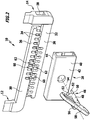
- FIG. 1 shows a perspective view of a total occupied by the reference numeral 10 first preferred embodiment of a surgical retraction device according to the invention.
- the retracting device 10 is provided in particular for spreading a sternum, not shown in the drawing, in order to allow an operator access to the open thorax, for example in the case of cardiac surgery.
- the retraction device 10 comprises two restraint devices 12 and 14.
- the restraint devices 12, 14 comprise spreader arms 16 and 18, respectively, which can be brought into a variable distance from one another by being displaced relative to each other along a retraction direction 20 in a manner to be described below.
- the retraction direction 20 is therefore also a displacement direction of the retraction device.
- each Sp includes a first portion 22 which is configured L-shaped, wherein the bend in the direction of the other Sp Schwarzarmes 18, 16 points.
- each spreading arm 16, 18 comprises a second section 24, which is mounted on the first section 22 such that it can pivot about an axis of rotation.
- the axis of rotation is oriented perpendicular to a spreader plane defined by the spreader arms 16, 18, in which the sternum is spread using the retraction device 10.
- the second sections 24 are rectilinear and elongated and pivotally mounted at approximately the center thereof at the first portions 22.
- a retaining element 26 is held on every second section 24.
- the retention members 26 each include a bracket that can be applied to the sternum.
- the retaining elements 26 of the spreading arms 16, 18 are thereby applied to both Sternumhiern that they can be spread with movement of the spreading arms 16, 18.
- the retaining elements 26 may be held in a positionally variable manner on the second sections 24, for example, be mounted pivotably relative to the spreading plane or be displaceable along the second sections 24.
- the retractor 10 includes a retainer 28 for holding the retainers 12, 14 together.
- the Retaining devices 12, 14 holding arms 30 and 32, respectively.
- Both support arms 30, 32 are rectilinear and elongated designed in the form of rails, the narrow sides 34 and broad sides 36 have.
- the holding arm 30 is preferably integrally connected to the spreader 16 with its first portion 22, and that at the opposite end of the second portion 24 of the first portion 22.
- the holding arm 30 is angled relative to the first portion 22, preferably 90 °, wherein it Direction of the Sp Drllarms 18 points.
- the holding arm 32 is preferably fixed in one piece on the first section 22 of the spreading arm 18.
- the holding arm 32 is angled relative to the first portion 22, preferably by 90 °, pointing in the direction of the Sp lanternarms 16.
- the connection on the first section 22 takes place at its end opposite the second section 24.
- the first portion 22 of the Sp Schwarzarms 18 has a passage opening 38.
- the holding arm 30 can pass through the clearance opening 38 without play or engage in it and thereby be guided on the spreader arm 18. If the retraction device 10 assumes an unspread position (FIG. FIG. 1 ), in which the retaining elements 26 of both spreading arms 16, 18 abut each other, the holding arm 30 passes through the passage opening 38. Even with slightly retraction retraction device 10 (not shown), the support arm 30 from the Sp Schwarzarm 18 can still be performed.
- the support arms 30, 32 are aligned in a plane aligned with each other and arranged so that narrow sides 34 face each other.
- the holding device 28 comprises a housing 40, which is designed as a flat housing.
- the housing 40 accordingly has two broad sides 42 and two narrow sides 44.
- the broad sides 42 and narrow sides 44 form a jacket, which surrounds both holding arms 30, 32 and in particular surrounds.
- the housing 40 is closed in other words in the circumferential direction of the support arms 30, 32 in itself.
- the support arms 30, 32 engage from opposite sides in the housing 40 and can pass through this. ever After how far the retraction device 10 is spread and which spreading position occupy the spreading arms 16, 18, the holding arms 30, 32 with their free ends still protrude from the housing 40. If the retraction device 10 is spread wide, the free ends of the holding arms 30, 32 can also be arranged in the housing 40.
- the housing 40 is about the holder of the retaining means 12, 14 and also their leadership when the support arms 30, 32 are displaced relative to the housing 40 and relative to each other along the retraction direction 20.
- the retraction device 10 can rest flat on the chest.
- the drive device 46 has a drive element 48, which in the present case is configured as a pin wheel 50.
- the pin wheel 50 is of cylindrical design, wherein it comprises two pins 52 on a front side arranged in the housing 40.
- the pins 52 are diametrically opposite each other with respect to a pinion 50 defined axis of rotation 54.
- the axis of rotation 54 is aligned perpendicular to the spreading plane.
- an actuating element 56 of the drive device 46 is held on the pin wheel 50.
- the actuating element 56 is manually operable and in the present case configured as a crank 58.
- the pin wheel 50 and the associated crank 58 are rotatably mounted on the housing 40 about the axis of rotation 54.
- crank 58 is removable from the pinion 50 or, together with the pinion 50, from the housing 40 in order, in application of the retraction device 10, to allow an operator after spread of the sternum an even better access to the surgical field.
- the toothed rows 60 are arranged on the holding arms 30, 32, in each case on the respective other holding arm 30, 32 facing narrow side 34.
- Each row of teeth 60 includes a plurality of teeth, of which 11 present Teeth are provided.
- the teeth are formed by forming on the narrow sides 34 on the holding arms 30, 32 recesses in which the remaining teeth have been removed.
- the teeth are each equally spaced and extend from the free ends of the support arms 30, 32 over approximately 60% of their length.
- the pin gear 50 and the rows of teeth 60 form drive rack toothing, which are designed as linear drives.
- Both rows of teeth 60 can couple simultaneously with pin wheel 50 so that both retainers 12, 14 can be driven using only one crank 58 and displaced relative to each other.
- the crank 58 and thus the pin wheel 50 about the axis of rotation 54 the pins 52 can pass in alternating engagement with the teeth on the support arms 30 and 32 and thereby displace both support arms 30, 32 along the retraction direction 20 relative to each other. Since both holding arms 30, 32 can be driven, the rows of teeth 60 are also referred to as drive tracks 62 of the drive device 46.
- both holding arms 30, 32 relative to each other and relative to the housing 40 along the retraction direction 20 are moved against the same. Because the pin gear 50 meshes with both rows of teeth 60, in one revolution, the support arms 30, 32 are displaced relative to each other by a distance twice as large as if only one support arm 30, 32 were driven by a row of teeth 60. This makes it possible to give the retraction device 10 a compact design. As in particular from FIG. 1 As can be seen, the support arms 30, 32 may be sized so short that they are unspread Retraction device 10 does not or only slightly beyond the other spreader 16, 18 protrude.
- the holding device 28, the pin wheel 50 and the crank 58, with respect to the retraction direction 20, are arranged in a median plane perpendicular to the spreader plane between the spreader arms 16, 18.
- the holding device 28, the pin wheel 50 and the crank 58 are arranged in the middle between the first sections 22. If the spreading arms 16, 18 are spread apart, the retaining arms 30, 32 thereby continue to be held against one another via the housing 40.
- the arrangement of the rows of teeth 60 at least partially within the housing 40 reduces the likelihood that foreign bodies, in particular surgical suture, will catch on the rows of teeth 60. This allows a more reliable function of the retraction device 10.
- the retraction device 10 has only a slight wear between components rubbing against each other.
- the housing 40 on the one hand and the pin wheel 50 on the other hand are manufactured or treated wear-reducing, for example by surface or heat treatment such as nitriding, surface hardening, boriding, case hardening or the like. A targeted difference in hardness of, for example, at least about 25% between the two friction partners is possible.
- the materials can be adapted to each other, for example, a combination of materials made of ceramic and metal or plastic and metal.
- plain bearings and / or ball bearings are possible to reduce the friction between the pinion 50 and the housing 40.
- Corresponding materials and / or surface or heat treatments are also possible in other components, in particular the cooperating pin 52 and rows of teeth 60th
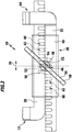
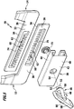
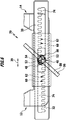
- FIGS. 4 to 6 show a second, in total occupied by the reference numeral 70 advantageous embodiment of a retraction device according to the invention.
- the achievable with the retractor 10 advantages can also be achieved with the retraction device 70, so that in this regard, reference can be made to avoid repetition of the above explanations.
- identical reference numerals are used and the essential differences are discussed.
- the holding arms 30, 32 are arranged parallel to each other and lie flat over their broad sides 36 against each other, so that they can lead each other when moving.
- both holding arms 30, 32 are guided by the housing 40.
- the housing 40 is not self-contained in the retraction device 70 in the circumferential direction of the holding arms 30, 32.
- Opposite a closed broad side 42 the broad side of the housing 40 is opened, so that the housing 40 has a C-shaped configuration in cross-section. This serves to fix the drive element 48 with a fixing element 72 from the side opposite the closed broad side 42 on the housing 40.
- the holding arms 30, 32 are in the longitudinal direction (corresponding to the retraction direction 20) extending slots 74.
- the rows of teeth 60 are disposed at edges of the slots 74, wherein the teeth of the rows of teeth 60 are formed as projections of the edges of the slots 74.
- Each row of teeth extends substantially over a longitudinal edge of a slot 74.
- the teeth of both rows of teeth 60 face each other, so that the pin gear 50 can simultaneously mesh with the rows of teeth 60 of both support arms 30, 32 ( FIG. 6 ).
- the row of teeth 60 in the support arm 30 points in a direction away from the retaining elements 26 direction, and the row of teeth 60 in the support arm 32 points in the direction of the retaining elements 26th
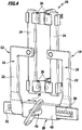
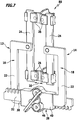
- FIGS. 7 to 9 show a total occupied by the reference numeral 80 third advantageous embodiment of a retraction device according to the invention.
- the achievable with the retractor 10 advantages can also be achieved with the retraction device 80, so that reference is made in this regard to avoid repetition of the above explanations.
- identical reference numerals are used, and the essential differences are described.
- the holding arms 30, 32, as well as in the retraction device 70 lie flat against one another via broad sides 36.
- the rows of teeth 60 are arranged on narrow sides 34, in directions pointing away from each other.
- the support arm 30 has the row of teeth 60 away from the retention members 26 and the support arm 32 has the row of teeth 60 toward the retention members 26.
- the rows of teeth 60 extend from the respective free end of a support arm 30, 32 over approximately 60% of its length.
- the rows of teeth 60 are formed by 34 recesses are formed on the support arms 30, 32 on the narrow sides, so that the non-recessed areas form teeth of the rows of teeth 60.
- the housing 40 like the housing 40 of the retraction device 70 in the circumferential direction of the support arms 30, 32 is not self-contained, but it has a cross-sectionally substantially C-shaped configuration.
- the housing 40 on the narrow sides 44 comprises two convex bulges, so that within the housing 40, a receiving space is provided for two drive elements 82 and 84 of the drive means 46.
- the drive elements 82, 84 are configured as gears 83 and 85, respectively.
- a further drive element 86 is arranged in the form of a gear 87 which meshes with both gears 83 and 85 simultaneously and rotatably connected to a drive body 88 of the drive means 46 is connected.
- the drive body 88 replaces the pinion 50 of the retraction device 10 at the retraction device 80, and the crank 58 is fixed to it.
- the drive body 88 and thus the gear 87 are rotatably mounted on the housing 40 about the axis of rotation 54 perpendicular to the spreading plane.
- the gears 83 and 85 are rotated simultaneously about axes of rotation 89 and 90 perpendicular to the spreading plane. All axes of rotation 54, 89, 90 are arranged in a common plane, namely the center plane of the retraction device 80.
- each two pins 91 which are diametrically opposed to each other with respect to the respective rotation axis 89 and 90 and are in engagement with the rows of teeth 60.
- gears 83, 85, 87 makes it possible to form a gear 92 with the drive means 46.
- a speed (number of revolutions) of the crank 58 can be over- or reduced by the gear 92 to adjust the speed of the gears 83, 85 according to the requirements.
- the holding arms 30, 32 can be displaced differently far relative to each other during each rotation of the crank 58.
- gears 83, 85 and 87 are interchangeable in order to adjust the over- or reduction, whereby the retractor 80 is given a high versatility.
Landscapes
- Health & Medical Sciences (AREA)
- Life Sciences & Earth Sciences (AREA)
- Surgery (AREA)
- Heart & Thoracic Surgery (AREA)
- Engineering & Computer Science (AREA)
- Biomedical Technology (AREA)
- Nuclear Medicine, Radiotherapy & Molecular Imaging (AREA)
- Medical Informatics (AREA)
- Molecular Biology (AREA)
- Animal Behavior & Ethology (AREA)
- General Health & Medical Sciences (AREA)
- Public Health (AREA)
- Veterinary Medicine (AREA)
- Surgical Instruments (AREA)
Claims (15)
- Dispositif de rétraction chirurgical, notamment écarteur sternal pour assurer un écartement d'un sternum ayant été coupé, comprenant un premier système de retenue (12) et un deuxième système de retenue (14) possédant chacun un bras écarteur respectif (16, 18) sur lequel est monté au moins un élément de retenue (26), et comprenant également un système de maintien (28) pour assurer le maintien des systèmes de retenue (12, 14) l'un contre l'autre, ainsi qu'un système d'entraînement (46), qui permet de faire varier la distance entre les bras écarteurs (16, 18) le long d'une direction de rétraction (20), afin de les amener dans une position écartée,
dispositif de rétraction
dans lequel les systèmes de retenue (12, 14) possèdent chacun un bras de maintien (30, 32) relié au bras écarteur (16, 18) respectivement correspondant,
dans lequel les deux bras de maintien (30, 32) assurent un couplage avec le système d'entraînement (46), et, par l'intermédiaire de celui-ci, peuvent coulisser l'un par rapport à l'autre et par rapport au système de maintien (28), le long d'une direction de coulissement,
dans lequel le système d'entraînement (46) comprend au moins un élément d'entraînement (48) et les bras de maintien (30, 32) comportent respectivement une voie d'entraînement (62) s'étendant dans la direction de coulissement, et
dans lequel ledit au moins un élément d'entraînement (48) interagit avec la voie d'entraînement (62) respective,
caractérisé en ce que les bras de maintien (30, 32) présentent des côtés larges (36) et des côtés étroits (34), et en ce que les bras de maintien (30, 32) s'appuient à plat l'un sur l'autre par l'intermédiaire des côtés larges (36) respectifs, au moins dans une zone de chevauchement des voies d'entraînement et de manière à ce que les bras de maintien se guident réciproquement l'un par rapport à l'autre lors du coulissement. - Dispositif de rétraction selon la revendication 1, caractérisé en ce que la direction de coulissement est orientée parallèlement à la direction de rétraction (20).
- Dispositif de rétraction selon l'une des revendications précédentes, caractérisé en ce que les bras de maintien (30, 32), lors de l'actionnement du système d'entraînement (46), peuvent coulisser de la même distance de déplacement par rapport au système de maintien (28).
- Dispositif de rétraction selon l'une des revendications précédentes, caractérisé en ce que les bras de maintien (30, 32) sont réalisés en forme de glissière.
- Dispositif de rétraction selon l'une des revendications précédentes, caractérisé en ce que le système de maintien (28) comporte ou forme un boitier (40), qui entoure au moins partiellement les bras de maintien (30, 32), de préférence en ce que le boitier (40) entoure complètement ou sensiblement complètement les bras de maintien (30, 32).
- Dispositif de rétraction selon l'une des revendications précédentes, caractérisé en ce que le système de maintien (28) forme un guidage pour au moins l'un des bras de maintien (30, 32).
- Dispositif de rétraction selon l'une des revendications précédentes, caractérisé en ce que le système de maintien (28) et/ou le système d'entraînement (46) est agencé, en se référant à la direction de rétraction (20), au milieu ou sensiblement au milieu entre les bras écarteurs (16, 18).
- Dispositif de rétraction selon l'une des revendications précédentes, caractérisé en ce que ledit au moins un élément d'entraînement (48) est monté rotatif dans le système de maintien (28) autour d'un axe de rotation (54) perpendiculaire à la direction de coulissement, et/ou en ce que le système d'entraînement (46) comprend, pour agir sur ledit au moins un élément d'entraînement (48), au moins un élément d'actionnement (56) pouvant être actionné manuellement et se présentant sous la forme d'une manivelle (58) ou d'une poignée tournante.
- Dispositif de rétraction selon l'une des revendications précédentes, caractérisé en ce que la voie d'entraînement (62) est réalisée en tant que rangée de dents (60) agencée sur le bras de maintien (30, 32) respectif, et en ce que ledit au moins un élément d'entraînement (48) est réalisé en tant que roue à tenons (50) ou roue dentée (83, 85, 87), qui vient engrener avec la rangée de dents (60).
- Dispositif de rétraction selon l'une des revendications précédentes, caractérisé en ce qu'au moins un bras de maintien (30, 32) comporte un trou oblong (74) orienté le long de la direction de coulissement et sur le bord duquel est agencée la voie d'entraînement (62).
- Dispositif de rétraction selon l'une des revendications précédentes, caractérisé en ce que les voies d'entraînement (62) sont agencées sur des côtés mutuellement opposés des bras de maintien (30, 32).
- Dispositif de rétraction selon l'une des revendications précédentes, caractérisé en ce que les bras de maintien (30, 32) présentent des côtés larges (36) et des côtés étroits (34), et en ce que les voies d'entraînement (62) sont agencées sur les côtés étroits (34).
- Dispositif de rétraction selon l'une des revendications précédentes, caractérisé en ce que le système d'entraînement (46) comprend un élément d'entraînement (48), qui interagit avec les voies d'entraînement (62) des deux bras de maintien (30, 32), ou bien en ce que le système d'entraînement (46) comprend deux éléments d'entraînement (82, 84), chaque élément d'entraînement (82, 84) interagissant avec une voie d'entraînement (62) d'un bras de maintien (30, 32).
- Dispositif de rétraction selon la revendication 13, caractérisé en ce que les éléments d'entraînement (82, 84) peuvent être entraînés en commun, de préférence en ce que le système d'entraînement (46) comprend un élément d'entraînement (86) couplé à l'élément d'actionnement (56) et engrenant avec les deux éléments d'entraînement (82, 84).
- Dispositif de rétraction selon l'une des revendications précédentes, caractérisé en ce que le système d'entraînement (46) comprend ou forme une transmission (92), à l'aide de laquelle il est possible de faire varier une vitesse de rotation de l'élément d'entraînement (82, 84) réalisé sous forme de corps rotatif, notamment sous forme de roue dentée (83, 85) ou de roue à tenons (50).
Priority Applications (1)
| Application Number | Priority Date | Filing Date | Title |
|---|---|---|---|
| EP18168393.9A EP3400880A1 (fr) | 2013-03-21 | 2014-02-05 | Dispositif de rétraction chirurgicale |
Applications Claiming Priority (2)
| Application Number | Priority Date | Filing Date | Title |
|---|---|---|---|
| DE102013102902.7A DE102013102902A1 (de) | 2013-03-21 | 2013-03-21 | Chirurgische Retraktionsvorrichtung |
| PCT/EP2014/052248 WO2014146824A1 (fr) | 2013-03-21 | 2014-02-05 | Dispositif de rétraction chirurgicale |
Related Child Applications (1)
| Application Number | Title | Priority Date | Filing Date |
|---|---|---|---|
| EP18168393.9A Division EP3400880A1 (fr) | 2013-03-21 | 2014-02-05 | Dispositif de rétraction chirurgicale |
Publications (2)
| Publication Number | Publication Date |
|---|---|
| EP2976021A1 EP2976021A1 (fr) | 2016-01-27 |
| EP2976021B1 true EP2976021B1 (fr) | 2018-04-25 |
Family
ID=50070544
Family Applications (2)
| Application Number | Title | Priority Date | Filing Date |
|---|---|---|---|
| EP14703334.4A Active EP2976021B1 (fr) | 2013-03-21 | 2014-02-05 | Dispositif de rétraction chirurgicale |
| EP18168393.9A Withdrawn EP3400880A1 (fr) | 2013-03-21 | 2014-02-05 | Dispositif de rétraction chirurgicale |
Family Applications After (1)
| Application Number | Title | Priority Date | Filing Date |
|---|---|---|---|
| EP18168393.9A Withdrawn EP3400880A1 (fr) | 2013-03-21 | 2014-02-05 | Dispositif de rétraction chirurgicale |
Country Status (5)
| Country | Link |
|---|---|
| US (1) | US9872676B2 (fr) |
| EP (2) | EP2976021B1 (fr) |
| JP (1) | JP6325079B2 (fr) |
| DE (1) | DE102013102902A1 (fr) |
| WO (1) | WO2014146824A1 (fr) |
Families Citing this family (18)
| Publication number | Priority date | Publication date | Assignee | Title |
|---|---|---|---|---|
| ATE524121T1 (de) | 2004-11-24 | 2011-09-15 | Abdou Samy | Vorrichtungen zur platzierung eines orthopädischen intervertebralen implantats |
| CN102292990B (zh) * | 2008-11-25 | 2016-10-05 | 汤姆森特许公司 | 对视频编码和解码进行基于稀疏性的去伪像滤波的方法和装置 |
| US20120130180A1 (en) | 2009-04-13 | 2012-05-24 | Physcient, Inc. | Methods and devices to decrease tissue trauma during surgery |
| US8764806B2 (en) | 2009-12-07 | 2014-07-01 | Samy Abdou | Devices and methods for minimally invasive spinal stabilization and instrumentation |
| US8845728B1 (en) | 2011-09-23 | 2014-09-30 | Samy Abdou | Spinal fixation devices and methods of use |
| US20130226240A1 (en) | 2012-02-22 | 2013-08-29 | Samy Abdou | Spinous process fixation devices and methods of use |
| US9198767B2 (en) | 2012-08-28 | 2015-12-01 | Samy Abdou | Devices and methods for spinal stabilization and instrumentation |
| US9320617B2 (en) | 2012-10-22 | 2016-04-26 | Cogent Spine, LLC | Devices and methods for spinal stabilization and instrumentation |
| DE102013110717A1 (de) | 2013-09-27 | 2015-04-02 | Aesculap Ag | Retraktor |
| WO2015112923A1 (fr) * | 2014-01-24 | 2015-07-30 | Contour Surgical Inc | Dispositifs écarteurs et procédés d'utilisation et de fabrication associés |
| CN110448434B (zh) * | 2014-10-29 | 2021-10-01 | 关节活动系统公司 | 用于增加人体关节的活动范围的矫形器 |
| US10857003B1 (en) | 2015-10-14 | 2020-12-08 | Samy Abdou | Devices and methods for vertebral stabilization |
| US10973648B1 (en) | 2016-10-25 | 2021-04-13 | Samy Abdou | Devices and methods for vertebral bone realignment |
| US10744000B1 (en) | 2016-10-25 | 2020-08-18 | Samy Abdou | Devices and methods for vertebral bone realignment |
| US11179248B2 (en) | 2018-10-02 | 2021-11-23 | Samy Abdou | Devices and methods for spinal implantation |
| US10959716B2 (en) * | 2019-02-11 | 2021-03-30 | Warsaw Orthopedic, Inc. | Surgical retractor system and method |
| FR3093417A1 (fr) * | 2019-03-07 | 2020-09-11 | Allyon | Outil d’ecartement des tissus pendant des operations de chirurgie |
| CN110353744B (zh) * | 2019-07-30 | 2021-03-23 | 青岛大学附属医院 | 一种用于胸外科临床的胸骨撑开器 |
Citations (2)
| Publication number | Priority date | Publication date | Assignee | Title |
|---|---|---|---|---|
| FR2657246A1 (fr) * | 1990-01-25 | 1991-07-26 | Massaad Raymond | Ecarteur autostatique pour la chirurgie osseuse. |
| US20100185059A1 (en) * | 2005-03-07 | 2010-07-22 | Jason Scott Sperling | Methods and apparatus for performing minimally invasive surgery |
Family Cites Families (49)
| Publication number | Priority date | Publication date | Assignee | Title |
|---|---|---|---|---|
| US979305A (en) | 1910-05-06 | 1910-12-20 | Charlie D Hunt | Wipe-joint pipe-holder. |
| US1664932A (en) * | 1925-10-03 | 1928-04-03 | Juricinec Francois | Monkey wrench |
| US2670731A (en) | 1952-02-11 | 1954-03-02 | Zoll Carl Michael | Abdominal retractor attachment |
| DE1769072A1 (de) | 1957-12-02 | 1971-08-12 | Exxon Research Engineering Co | Verfahren zum kontinuierlichen Kompoundieren von Isoolefinpolymeren |
| US3195536A (en) | 1962-09-05 | 1965-07-20 | Avco Corp | Illuminated appliances |
| US3522799A (en) | 1967-06-21 | 1970-08-04 | William K Gauthier | Surgical retractor device |
| US3592199A (en) | 1970-02-09 | 1971-07-13 | Medical Products Corp | Autoclavable surgical instrument illumination |
| US3749088A (en) | 1971-06-23 | 1973-07-31 | W Kohlmann | Surgical retractor device |
| US3796214A (en) | 1972-12-04 | 1974-03-12 | R Davis | Perineal retractor |
| US3986854A (en) | 1974-09-23 | 1976-10-19 | Vicon Products Corporation | Method of making autoclavable instrument with sintered fiber glass rod |
| DE3023266A1 (de) | 1980-06-21 | 1982-01-07 | Original Hanau Heraeus Gmbh, 6450 Hanau | Wundhaken fuer chirurgische zwecke |
| DE3367727D1 (en) | 1982-07-30 | 1987-01-08 | Heraeus Gmbh W C | Retractor for surgical purposes |
| DE3301890C2 (de) | 1983-01-21 | 1986-04-10 | W.C. Heraeus Gmbh, 6450 Hanau | Wundhaken |
| US4566448A (en) | 1983-03-07 | 1986-01-28 | Rohr Jr William L | Ligament tensor and distal femoral resector guide |
| US4570614A (en) | 1983-05-06 | 1986-02-18 | Jack Bauman | Laryngoscope with disposable blade and light conductor |
| US4562832A (en) | 1984-01-21 | 1986-01-07 | Wilder Joseph R | Medical instrument and light pipe illumination assembly |
| US4597030A (en) | 1985-01-31 | 1986-06-24 | American Hospital Supply Corporation | Surgical illuminator |
| US4747394A (en) * | 1986-10-08 | 1988-05-31 | Watanabe Orthopedic Systems, Inc. | Spinal retractor |
| US5002547A (en) | 1987-02-07 | 1991-03-26 | Pfizer Hospital Products Group, Inc. | Apparatus for knee prosthesis |
| US4805599A (en) | 1987-06-25 | 1989-02-21 | Cedar Surgical, Inc. | Framework for supporting surgical instruments at a surgical wound |
| DE3736066C1 (de) | 1987-10-24 | 1988-11-10 | Aesculap Werke Ag | Wundhaken |
| US4867139A (en) | 1988-02-08 | 1989-09-19 | Girzadas Daniel V | Hands-free surgical instrument for retracting muscles and tissues |
| US4932395A (en) | 1988-05-18 | 1990-06-12 | Mehdizadeh Hamid M | Hemi-laminectomy retractor attachment device |
| US4971038A (en) | 1989-04-26 | 1990-11-20 | Farley Daniel K | Table mounted surgical retractor |
| US5027793A (en) | 1990-03-30 | 1991-07-02 | Boehringer Mannheim Corp. | Surgical retractor |
| FR2692468B1 (fr) | 1992-06-19 | 1994-09-23 | Grae Henry | Ecarteur opératoire pour les interventions chirurgicales sur la colonne vertébrale. |
| US5364399A (en) | 1993-02-05 | 1994-11-15 | Danek Medical, Inc. | Anterior cervical plating system |
| US5303694A (en) | 1993-02-09 | 1994-04-19 | Mikhail Michael W E | Method for performing hip surgery and retractor for use therein |
| US5363841A (en) | 1993-07-02 | 1994-11-15 | Coker Wesley L | Retractor for spinal surgery |
| DE19522879A1 (de) | 1995-06-23 | 1997-01-02 | Aesculap Ag | Chirurgischer Wundsperrer |
| FR2742330B1 (fr) * | 1995-12-18 | 1998-05-15 | Maurice Lanzoni | Ecarteur universel et modulaire de chirurgie |
| CA2198036C (fr) | 1996-02-20 | 2000-12-05 | Charles S. Taylor | Plate-forme d'acces pour la dissection de l'artere thoracique interne |
| US5976171A (en) | 1996-02-20 | 1999-11-02 | Cardiothoracic Systems, Inc. | Access platform for internal mammary dissection |
| US5730757A (en) | 1996-02-20 | 1998-03-24 | Cardiothoracic Systems, Inc. | Access platform for internal mammary dissection |
| FR2758969B1 (fr) * | 1997-02-04 | 1999-04-30 | Jean Paul Couetil | Ecarteur sternal ou ecarteur thoracique |
| US6113536A (en) | 1998-09-30 | 2000-09-05 | A-Med Systems, Inc. | Device and method of attaching a blood pump and tubes to a surgical retractor |
| WO2001080725A1 (fr) | 2000-04-21 | 2001-11-01 | Viamedics, Llc | Dispositif d'acces chirurgical |
| US7824332B2 (en) | 2006-01-11 | 2010-11-02 | Mehdi Fakhrai | Retractor |
| US7794387B2 (en) | 2006-04-26 | 2010-09-14 | Medtronic, Inc. | Methods and devices for stabilizing tissue |
| US7922658B2 (en) * | 2006-11-09 | 2011-04-12 | Ebi, Llc | Surgical retractor device and related methods |
| US20080188718A1 (en) * | 2007-01-26 | 2008-08-07 | James Spitler | Surgical retractor with adjustable blades and method of use |
| US8062217B2 (en) * | 2007-01-26 | 2011-11-22 | Theken Spine, Llc | Surgical retractor with removable blades and method of use |
| US8092495B2 (en) * | 2008-04-04 | 2012-01-10 | The Cleveland Clinic Foundation | Spinal platform and method for delivering a therapeutic agent to a spinal cord target |
| AU2009234286B2 (en) | 2008-04-11 | 2015-02-12 | Physcient, Inc. | Methods and devices to decrease tissue trauma during surgery |
| EP2394584B1 (fr) | 2010-06-09 | 2014-04-16 | Karl Storz GmbH & Co. KG | Rétracteur chirurgical |
| US8636656B2 (en) * | 2011-08-16 | 2014-01-28 | Warsaw Orthopedic, Inc. | Retractor assemblies with blade drive mechanisms |
| DE102011053938A1 (de) | 2011-09-26 | 2013-03-28 | Aesculap Ag | Chirurgisches Retraktionssystem |
| DE202012100124U1 (de) * | 2012-01-13 | 2012-02-27 | Aesculap Ag | Chirurgische Retraktionsvorrichtung |
| DE102012100284A1 (de) | 2012-01-13 | 2013-07-18 | Aesculap Ag | Chirurgische Retraktionsvorrichtung |
-
2013
- 2013-03-21 DE DE102013102902.7A patent/DE102013102902A1/de not_active Withdrawn
-
2014
- 2014-02-05 EP EP14703334.4A patent/EP2976021B1/fr active Active
- 2014-02-05 JP JP2016503580A patent/JP6325079B2/ja active Active
- 2014-02-05 EP EP18168393.9A patent/EP3400880A1/fr not_active Withdrawn
- 2014-02-05 WO PCT/EP2014/052248 patent/WO2014146824A1/fr active Application Filing
-
2015
- 2015-09-11 US US14/851,468 patent/US9872676B2/en active Active
Patent Citations (2)
| Publication number | Priority date | Publication date | Assignee | Title |
|---|---|---|---|---|
| FR2657246A1 (fr) * | 1990-01-25 | 1991-07-26 | Massaad Raymond | Ecarteur autostatique pour la chirurgie osseuse. |
| US20100185059A1 (en) * | 2005-03-07 | 2010-07-22 | Jason Scott Sperling | Methods and apparatus for performing minimally invasive surgery |
Non-Patent Citations (1)
| Title |
|---|
| THEIS & SPIGGLE: "Mundhöhlen-Instrumentarium Oral Cavity Instruments", 31 December 2012 (2012-12-31), Overath, pages 1 - 76, XP055345330, Retrieved from the Internet <URL:http://www.spiggle-theis.com/pdf/mundhoehle.pdf> [retrieved on 20170214] * |
Also Published As
| Publication number | Publication date |
|---|---|
| US9872676B2 (en) | 2018-01-23 |
| EP2976021A1 (fr) | 2016-01-27 |
| DE102013102902A1 (de) | 2014-09-25 |
| JP2016514504A (ja) | 2016-05-23 |
| EP3400880A1 (fr) | 2018-11-14 |
| WO2014146824A1 (fr) | 2014-09-25 |
| US20160000419A1 (en) | 2016-01-07 |
| JP6325079B2 (ja) | 2018-05-16 |
Similar Documents
| Publication | Publication Date | Title |
|---|---|---|
| EP2976021B1 (fr) | Dispositif de rétraction chirurgicale | |
| EP2510888B1 (fr) | Dispositif de manipulation pour un instrument de chirurgie micro-invasive | |
| EP1649816B1 (fr) | Instrument endoscopique déviable | |
| DE4210724C1 (en) | Surgical instrument with expander in shaft portion - has expanding member mounting eccentrical on pinion meshing with central gear on shaft passing through stem | |
| DE102006003548B4 (de) | Zangen- oder Schereninstrument mit Getriebeverbindung | |
| EP2241262B1 (fr) | Dispositif de rétraction chirurgical | |
| DE1566076B1 (de) | Retraktorvorrichtung | |
| EP0888746B1 (fr) | Instrument chirurgical à tige tubulaire | |
| AT518032B1 (de) | Medizinisches instrument | |
| AT510714A4 (de) | Kupplungsvorrichtung für schubladen | |
| WO1994020033A1 (fr) | Instrument medical d'atherectomie | |
| DE202011051999U1 (de) | Chirurgisches Retraktionssystem | |
| WO1999053987A1 (fr) | Ensemble manchon de guidage flexible pour catheter | |
| DE2856386C2 (de) | Approximator für die anastomotische Chirurgie | |
| EP2510889A1 (fr) | Dispositif de manipulation pour un instrument de chirurgie micro-invasive | |
| DE10013331A1 (de) | Haltevorrichtung | |
| EP2653122B1 (fr) | Outil pour un instrument médical | |
| DE102012201983A1 (de) | Spreizer für die Herz- und Thoraxchirurgie | |
| DE102014101009A1 (de) | Knochenspreizer mit verdrehbaren Valven | |
| DE102014206930B4 (de) | Instrument, insbesondere medizinisch-endoskopisches Instrument | |
| DE102021119386A1 (de) | Abwinkelbarer Schaft für ein medizinisches Handinstrument | |
| DE102011088003A1 (de) | Medizinisches Instrument | |
| DE10145107B4 (de) | Füllstab für Endoskope | |
| DE102006036117B4 (de) | Chirurgisches Instrument zum Spreizen von zwei zueinander benachbarten Operationsöffnungen | |
| DE19719090A1 (de) | Chirurgisches Instrument |
Legal Events
| Date | Code | Title | Description |
|---|---|---|---|
| PUAI | Public reference made under article 153(3) epc to a published international application that has entered the european phase |
Free format text: ORIGINAL CODE: 0009012 |
|
| 17P | Request for examination filed |
Effective date: 20150917 |
|
| AK | Designated contracting states |
Kind code of ref document: A1 Designated state(s): AL AT BE BG CH CY CZ DE DK EE ES FI FR GB GR HR HU IE IS IT LI LT LU LV MC MK MT NL NO PL PT RO RS SE SI SK SM TR |
|
| AX | Request for extension of the european patent |
Extension state: BA ME |
|
| DAX | Request for extension of the european patent (deleted) | ||
| STAA | Information on the status of an ep patent application or granted ep patent |
Free format text: STATUS: EXAMINATION IS IN PROGRESS |
|
| 17Q | First examination report despatched |
Effective date: 20170222 |
|
| GRAP | Despatch of communication of intention to grant a patent |
Free format text: ORIGINAL CODE: EPIDOSNIGR1 |
|
| STAA | Information on the status of an ep patent application or granted ep patent |
Free format text: STATUS: GRANT OF PATENT IS INTENDED |
|
| INTG | Intention to grant announced |
Effective date: 20171106 |
|
| GRAA | (expected) grant |
Free format text: ORIGINAL CODE: 0009210 |
|
| GRAS | Grant fee paid |
Free format text: ORIGINAL CODE: EPIDOSNIGR3 |
|
| STAA | Information on the status of an ep patent application or granted ep patent |
Free format text: STATUS: THE PATENT HAS BEEN GRANTED |
|
| AK | Designated contracting states |
Kind code of ref document: B1 Designated state(s): AL AT BE BG CH CY CZ DE DK EE ES FI FR GB GR HR HU IE IS IT LI LT LU LV MC MK MT NL NO PL PT RO RS SE SI SK SM TR |
|
| REG | Reference to a national code |
Ref country code: GB Ref legal event code: FG4D Free format text: NOT ENGLISH |
|
| REG | Reference to a national code |
Ref country code: CH Ref legal event code: EP |
|
| REG | Reference to a national code |
Ref country code: AT Ref legal event code: REF Ref document number: 992006 Country of ref document: AT Kind code of ref document: T Effective date: 20180515 |
|
| REG | Reference to a national code |
Ref country code: IE Ref legal event code: FG4D Free format text: LANGUAGE OF EP DOCUMENT: GERMAN |
|
| REG | Reference to a national code |
Ref country code: DE Ref legal event code: R096 Ref document number: 502014008066 Country of ref document: DE |
|
| REG | Reference to a national code |
Ref country code: NL Ref legal event code: MP Effective date: 20180425 |
|
| REG | Reference to a national code |
Ref country code: LT Ref legal event code: MG4D |
|
| PG25 | Lapsed in a contracting state [announced via postgrant information from national office to epo] |
Ref country code: NL Free format text: LAPSE BECAUSE OF FAILURE TO SUBMIT A TRANSLATION OF THE DESCRIPTION OR TO PAY THE FEE WITHIN THE PRESCRIBED TIME-LIMIT Effective date: 20180425 |
|
| PG25 | Lapsed in a contracting state [announced via postgrant information from national office to epo] |
Ref country code: SE Free format text: LAPSE BECAUSE OF FAILURE TO SUBMIT A TRANSLATION OF THE DESCRIPTION OR TO PAY THE FEE WITHIN THE PRESCRIBED TIME-LIMIT Effective date: 20180425 Ref country code: ES Free format text: LAPSE BECAUSE OF FAILURE TO SUBMIT A TRANSLATION OF THE DESCRIPTION OR TO PAY THE FEE WITHIN THE PRESCRIBED TIME-LIMIT Effective date: 20180425 Ref country code: LT Free format text: LAPSE BECAUSE OF FAILURE TO SUBMIT A TRANSLATION OF THE DESCRIPTION OR TO PAY THE FEE WITHIN THE PRESCRIBED TIME-LIMIT Effective date: 20180425 Ref country code: FI Free format text: LAPSE BECAUSE OF FAILURE TO SUBMIT A TRANSLATION OF THE DESCRIPTION OR TO PAY THE FEE WITHIN THE PRESCRIBED TIME-LIMIT Effective date: 20180425 Ref country code: BG Free format text: LAPSE BECAUSE OF FAILURE TO SUBMIT A TRANSLATION OF THE DESCRIPTION OR TO PAY THE FEE WITHIN THE PRESCRIBED TIME-LIMIT Effective date: 20180725 Ref country code: PL Free format text: LAPSE BECAUSE OF FAILURE TO SUBMIT A TRANSLATION OF THE DESCRIPTION OR TO PAY THE FEE WITHIN THE PRESCRIBED TIME-LIMIT Effective date: 20180425 Ref country code: NO Free format text: LAPSE BECAUSE OF FAILURE TO SUBMIT A TRANSLATION OF THE DESCRIPTION OR TO PAY THE FEE WITHIN THE PRESCRIBED TIME-LIMIT Effective date: 20180725 |
|
| PG25 | Lapsed in a contracting state [announced via postgrant information from national office to epo] |
Ref country code: GR Free format text: LAPSE BECAUSE OF FAILURE TO SUBMIT A TRANSLATION OF THE DESCRIPTION OR TO PAY THE FEE WITHIN THE PRESCRIBED TIME-LIMIT Effective date: 20180726 Ref country code: LV Free format text: LAPSE BECAUSE OF FAILURE TO SUBMIT A TRANSLATION OF THE DESCRIPTION OR TO PAY THE FEE WITHIN THE PRESCRIBED TIME-LIMIT Effective date: 20180425 Ref country code: RS Free format text: LAPSE BECAUSE OF FAILURE TO SUBMIT A TRANSLATION OF THE DESCRIPTION OR TO PAY THE FEE WITHIN THE PRESCRIBED TIME-LIMIT Effective date: 20180425 Ref country code: HR Free format text: LAPSE BECAUSE OF FAILURE TO SUBMIT A TRANSLATION OF THE DESCRIPTION OR TO PAY THE FEE WITHIN THE PRESCRIBED TIME-LIMIT Effective date: 20180425 |
|
| PG25 | Lapsed in a contracting state [announced via postgrant information from national office to epo] |
Ref country code: PT Free format text: LAPSE BECAUSE OF FAILURE TO SUBMIT A TRANSLATION OF THE DESCRIPTION OR TO PAY THE FEE WITHIN THE PRESCRIBED TIME-LIMIT Effective date: 20180827 |
|
| REG | Reference to a national code |
Ref country code: DE Ref legal event code: R097 Ref document number: 502014008066 Country of ref document: DE |
|
| PG25 | Lapsed in a contracting state [announced via postgrant information from national office to epo] |
Ref country code: CZ Free format text: LAPSE BECAUSE OF FAILURE TO SUBMIT A TRANSLATION OF THE DESCRIPTION OR TO PAY THE FEE WITHIN THE PRESCRIBED TIME-LIMIT Effective date: 20180425 Ref country code: SK Free format text: LAPSE BECAUSE OF FAILURE TO SUBMIT A TRANSLATION OF THE DESCRIPTION OR TO PAY THE FEE WITHIN THE PRESCRIBED TIME-LIMIT Effective date: 20180425 Ref country code: RO Free format text: LAPSE BECAUSE OF FAILURE TO SUBMIT A TRANSLATION OF THE DESCRIPTION OR TO PAY THE FEE WITHIN THE PRESCRIBED TIME-LIMIT Effective date: 20180425 Ref country code: DK Free format text: LAPSE BECAUSE OF FAILURE TO SUBMIT A TRANSLATION OF THE DESCRIPTION OR TO PAY THE FEE WITHIN THE PRESCRIBED TIME-LIMIT Effective date: 20180425 Ref country code: EE Free format text: LAPSE BECAUSE OF FAILURE TO SUBMIT A TRANSLATION OF THE DESCRIPTION OR TO PAY THE FEE WITHIN THE PRESCRIBED TIME-LIMIT Effective date: 20180425 |
|
| PG25 | Lapsed in a contracting state [announced via postgrant information from national office to epo] |
Ref country code: SM Free format text: LAPSE BECAUSE OF FAILURE TO SUBMIT A TRANSLATION OF THE DESCRIPTION OR TO PAY THE FEE WITHIN THE PRESCRIBED TIME-LIMIT Effective date: 20180425 Ref country code: IT Free format text: LAPSE BECAUSE OF FAILURE TO SUBMIT A TRANSLATION OF THE DESCRIPTION OR TO PAY THE FEE WITHIN THE PRESCRIBED TIME-LIMIT Effective date: 20180425 |
|
| PLBE | No opposition filed within time limit |
Free format text: ORIGINAL CODE: 0009261 |
|
| STAA | Information on the status of an ep patent application or granted ep patent |
Free format text: STATUS: NO OPPOSITION FILED WITHIN TIME LIMIT |
|
| 26N | No opposition filed |
Effective date: 20190128 |
|
| PG25 | Lapsed in a contracting state [announced via postgrant information from national office to epo] |
Ref country code: SI Free format text: LAPSE BECAUSE OF FAILURE TO SUBMIT A TRANSLATION OF THE DESCRIPTION OR TO PAY THE FEE WITHIN THE PRESCRIBED TIME-LIMIT Effective date: 20180425 |
|
| REG | Reference to a national code |
Ref country code: CH Ref legal event code: PL |
|
| PG25 | Lapsed in a contracting state [announced via postgrant information from national office to epo] |
Ref country code: MC Free format text: LAPSE BECAUSE OF FAILURE TO SUBMIT A TRANSLATION OF THE DESCRIPTION OR TO PAY THE FEE WITHIN THE PRESCRIBED TIME-LIMIT Effective date: 20180425 Ref country code: LU Free format text: LAPSE BECAUSE OF NON-PAYMENT OF DUE FEES Effective date: 20190205 |
|
| REG | Reference to a national code |
Ref country code: BE Ref legal event code: MM Effective date: 20190228 |
|
| REG | Reference to a national code |
Ref country code: IE Ref legal event code: MM4A |
|
| PG25 | Lapsed in a contracting state [announced via postgrant information from national office to epo] |
Ref country code: AL Free format text: LAPSE BECAUSE OF FAILURE TO SUBMIT A TRANSLATION OF THE DESCRIPTION OR TO PAY THE FEE WITHIN THE PRESCRIBED TIME-LIMIT Effective date: 20180425 |
|
| PG25 | Lapsed in a contracting state [announced via postgrant information from national office to epo] |
Ref country code: LI Free format text: LAPSE BECAUSE OF NON-PAYMENT OF DUE FEES Effective date: 20190228 Ref country code: CH Free format text: LAPSE BECAUSE OF NON-PAYMENT OF DUE FEES Effective date: 20190228 |
|
| PG25 | Lapsed in a contracting state [announced via postgrant information from national office to epo] |
Ref country code: IE Free format text: LAPSE BECAUSE OF NON-PAYMENT OF DUE FEES Effective date: 20190205 |
|
| PG25 | Lapsed in a contracting state [announced via postgrant information from national office to epo] |
Ref country code: BE Free format text: LAPSE BECAUSE OF NON-PAYMENT OF DUE FEES Effective date: 20190228 |
|
| PG25 | Lapsed in a contracting state [announced via postgrant information from national office to epo] |
Ref country code: TR Free format text: LAPSE BECAUSE OF FAILURE TO SUBMIT A TRANSLATION OF THE DESCRIPTION OR TO PAY THE FEE WITHIN THE PRESCRIBED TIME-LIMIT Effective date: 20180425 |
|
| REG | Reference to a national code |
Ref country code: AT Ref legal event code: MM01 Ref document number: 992006 Country of ref document: AT Kind code of ref document: T Effective date: 20190205 |
|
| PG25 | Lapsed in a contracting state [announced via postgrant information from national office to epo] |
Ref country code: AT Free format text: LAPSE BECAUSE OF NON-PAYMENT OF DUE FEES Effective date: 20190205 |
|
| PG25 | Lapsed in a contracting state [announced via postgrant information from national office to epo] |
Ref country code: MT Free format text: LAPSE BECAUSE OF FAILURE TO SUBMIT A TRANSLATION OF THE DESCRIPTION OR TO PAY THE FEE WITHIN THE PRESCRIBED TIME-LIMIT Effective date: 20180425 |
|
| PG25 | Lapsed in a contracting state [announced via postgrant information from national office to epo] |
Ref country code: CY Free format text: LAPSE BECAUSE OF FAILURE TO SUBMIT A TRANSLATION OF THE DESCRIPTION OR TO PAY THE FEE WITHIN THE PRESCRIBED TIME-LIMIT Effective date: 20180425 |
|
| PG25 | Lapsed in a contracting state [announced via postgrant information from national office to epo] |
Ref country code: IS Free format text: LAPSE BECAUSE OF FAILURE TO SUBMIT A TRANSLATION OF THE DESCRIPTION OR TO PAY THE FEE WITHIN THE PRESCRIBED TIME-LIMIT Effective date: 20180825 |
|
| PG25 | Lapsed in a contracting state [announced via postgrant information from national office to epo] |
Ref country code: HU Free format text: LAPSE BECAUSE OF FAILURE TO SUBMIT A TRANSLATION OF THE DESCRIPTION OR TO PAY THE FEE WITHIN THE PRESCRIBED TIME-LIMIT; INVALID AB INITIO Effective date: 20140205 |
|
| PG25 | Lapsed in a contracting state [announced via postgrant information from national office to epo] |
Ref country code: MK Free format text: LAPSE BECAUSE OF FAILURE TO SUBMIT A TRANSLATION OF THE DESCRIPTION OR TO PAY THE FEE WITHIN THE PRESCRIBED TIME-LIMIT Effective date: 20180425 |
|
| PGFP | Annual fee paid to national office [announced via postgrant information from national office to epo] |
Ref country code: FR Payment date: 20230217 Year of fee payment: 10 |
|
| P01 | Opt-out of the competence of the unified patent court (upc) registered |
Effective date: 20230926 |
|
| PGFP | Annual fee paid to national office [announced via postgrant information from national office to epo] |
Ref country code: DE Payment date: 20240216 Year of fee payment: 11 Ref country code: GB Payment date: 20240222 Year of fee payment: 11 |