EP2975974B1 - Anordnung für einen gekühlten nahrungsmittelriegel - Google Patents
Anordnung für einen gekühlten nahrungsmittelriegel Download PDFInfo
- Publication number
- EP2975974B1 EP2975974B1 EP14768786.7A EP14768786A EP2975974B1 EP 2975974 B1 EP2975974 B1 EP 2975974B1 EP 14768786 A EP14768786 A EP 14768786A EP 2975974 B1 EP2975974 B1 EP 2975974B1
- Authority
- EP
- European Patent Office
- Prior art keywords
- arrangement
- holding
- canteens
- cooling
- food bar
- Prior art date
- Legal status (The legal status is an assumption and is not a legal conclusion. Google has not performed a legal analysis and makes no representation as to the accuracy of the status listed.)
- Active
Links
Images


Classifications
-
- A—HUMAN NECESSITIES
- A47—FURNITURE; DOMESTIC ARTICLES OR APPLIANCES; COFFEE MILLS; SPICE MILLS; SUCTION CLEANERS IN GENERAL
- A47F—SPECIAL FURNITURE, FITTINGS, OR ACCESSORIES FOR SHOPS, STOREHOUSES, BARS, RESTAURANTS OR THE LIKE; PAYING COUNTERS
- A47F10/00—Furniture or installations specially adapted to particular types of service systems, not otherwise provided for
- A47F10/06—Furniture or installations specially adapted to particular types of service systems, not otherwise provided for for restaurant service systems
-
- A—HUMAN NECESSITIES
- A47—FURNITURE; DOMESTIC ARTICLES OR APPLIANCES; COFFEE MILLS; SPICE MILLS; SUCTION CLEANERS IN GENERAL
- A47F—SPECIAL FURNITURE, FITTINGS, OR ACCESSORIES FOR SHOPS, STOREHOUSES, BARS, RESTAURANTS OR THE LIKE; PAYING COUNTERS
- A47F3/00—Show cases or show cabinets
- A47F3/04—Show cases or show cabinets air-conditioned, refrigerated
- A47F3/0404—Cases or cabinets of the closed type
- A47F3/0408—Cases or cabinets of the closed type with forced air circulation
- A47F3/0413—Cases or cabinets of the counter type
-
- A—HUMAN NECESSITIES
- A47—FURNITURE; DOMESTIC ARTICLES OR APPLIANCES; COFFEE MILLS; SPICE MILLS; SUCTION CLEANERS IN GENERAL
- A47F—SPECIAL FURNITURE, FITTINGS, OR ACCESSORIES FOR SHOPS, STOREHOUSES, BARS, RESTAURANTS OR THE LIKE; PAYING COUNTERS
- A47F3/00—Show cases or show cabinets
- A47F3/04—Show cases or show cabinets air-conditioned, refrigerated
- A47F3/0482—Details common to both closed and open types
Definitions
- the present invention relates to a food bar arrangement according to the first part of claim 1.
- US 2 201 696 discloses a refrigerated display showcase with an insulating housing and cooling means on the front and rear sides of the housing.
- the opening to the housing is so located that the housing provides a cold air trap with walls and a bottom.
- the walls have such a height that by gravity a sufficient depth of cold air can be retained within the housing irrespective of any opening closure. Also here it is difficult to obtain an even temperature distribution in packages held in the housing.
- fan blowers for blowing cold air onto the products e.g. from above, or from below or sideways onto the canteens.
- Another particular object is to provide an arrangement which is flexible and provides an excellent access to the products for the customers.
- An object is to provide a high standard refrigerated food bar arrangement, particularly of the type intended for self-service, but also for other purposes, e.g. in canteens in schools or restaurants or imbiss stands when staff are serving the customers.
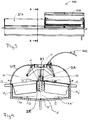
- Fig.1 shows a food bar arrangement 100, e.g. a salad bar, according to a first embodiment of the invention. It comprises a canteen or pan holding arrangement 10 adapted to receive and hold a plurality of canteens or pans 1A 1 ,...,1A 9 ' in which fresh food products will be placed. It further comprises a refrigerating arrangement 20 adapted to cool the canteens, and the food products provided therein for keeping the food products at a desired temperature, e.g. above 0° but below 8° C, or within a more specified temperature interval.
- a desired temperature e.g. above 0° but below 8° C
- the holding arrangement 10 comprises a cupboard or a bench arrangement 15 comprising a cold well adapted to receive the canteens or pans in such a manner that openings of the canteens or pans make the food accessible for a user from a first and a second outer side section 15A, 15B of the holding arrangement 10 allowing the user to choose and pick from the canteens or pans.
- the arrangement 100 also comprises a cover arrangement 30 adapted to cover the upper, open sections of the canteens or pans so that they will be covered and protected in time periods when not access is required for serving a user, or for refilling the canteens or similar.
- the covering arrangement in some embodiments also serve the purpose of assisting in the desired even temperature distribution. In some embodiments, though, the covering arrangement may be dispensed with.
- the refrigerating arrangement 20 comprises one or more cooling elements.
- the cooling arrangement 20 comprising cooling elements is arranged with respect to, or in, the holding arrangement 10 such that, when the canteens are taken up therein, each canteen back wall distant from an opposite canteen front wall located adjacent an inner side of the holding arrangement 10 at the outer end sections of the holding arrangement 10 where customer access is provided, will be located close to, facing it, preferably throughout the entire area forming the back wall.
- the holding arrangement 10 comprises holding means adapted to hold the canteens or pans in an inclined position such that the outer, upper ends or side edges, of the canteens are arranged at a lower level than opposing inner, upper ends or side edges. Bottom sections of the holding arrangement are disposed such that a distance is left between the bottom surface of the holding arrangement forming a cold well and the bottom portions of the canteens, the distance d (see Fig. 4 ) being larger below the cooling arrangement 20 than at the outer end portions.
- the cooling element or cooling elements are thus arranged to be located adjacent the outer sides of the back walls of the canteens in a mounted position in the holding arrangement 10.
- a first portion 20A of the cooling arrangement 20 protrudes so as to be arranged above the upper edges of the back walls of the canteens when they are placed in the holding arrangement 10.
- a second section 20B of the cooling arrangement 20 extends downwards towards, but ending at a certain distance from, the bottom of the well or trough of the holding arrangement 10 such that it will be located adjacent substantially the entire back wall of each canteen.
- the cooling arrangement 20 Through the positioning of the canteens in an inclined manner, outwardly downwards away from the cooling arrangement 20, and the first portion 20A of the cooling arrangement extending upwardly above the inner upper side edges of the back walls, and the cooling arrangement 20 being divided into a (communicating) upper and lower portion, separated by means of a dividing plate 24 (see Fig. 4 ), the cooled air surrounding the upper inner part will flow downwards, outwards above the canteens containing the food, due to the dividing plate hence not being allowed to pass, flow, vertically to the cold well, but is prevented to do so by the dividing plate 24.
- the cooling arrangement 10 Through the second lower portion of the cooling arrangement 10 covering the entire back walls of the canteens and a larger space being formed adjacent, below, the cooling arrangement 10, air with a lower temperature will be distributed and flow towards the outer end sections, under the canteens, so that the canteens or pans, and food provided therein, will be efficiently and evenly cooled from below as well as from above.
- the arrangement 100 comprises a holding arrangement 10 which is adapted to receive two parallel rows of canteens 1A 1 -1A 9 ,1A 1 '-1A 9 ', the cooling arrangement 20 protruding in a central portion of the bar arrangement above the inner, upper back edges of mounted canteens, and the canteens in each row being held so as to form an inclination angle ⁇ of between 5° and 10°, preferably between 6° and 9°, most preferably around 7.5° with a horizontal plane, see Fig. 4 .
- the bottom sections of the holding arrangement 10 are preferably also inclined such that an angle ⁇ of about 165°-175° is formed at the intersection of the two bottom planes, the vertex being located below the lower end of the cooling arrangement 20.
- about 30% of the cooling arrangement (the cooling elements), or an upper portion thereof providing about 30% of the cooling effect, is located above the upper edges of the back walls of the canteens when arranged in the holding arrangement, whereas about 70% is located below the upper edges, forming a lower portion, in the shown embodiment between opposite back walls of canteens in the two rows.
- Fig 2 is a section through an arrangement as shown in Fig 1 which illustrates a refrigerating arrangement 20' comprising an inlet 22 at an upper end of the cooling arrangement which is the coolest part, and which is adapted to be connected to a throttle valve (not shown), the cooling arrangement comprising conduits through which a cooling fluid is circulating back and forth throughout the length of the holding arrangement in a number of turns until, at the lower part of the cooling arrangement 20 where it is connected to an outlet 23, which is adapted to be connected to a compressor (not shown).
- FIG. 2 also an upper and a lower portion 26, 26' of an evaporator are shown, i.e. an evaporator is divided into a lower and an upper evaporation portion.
- a dividing plate 24 forms an interface between the portions of the cooling arrangement being located above the upper edges of canteens mounted in the holding arrangement and the lower portion respectively as discussed more thoroughly with reference to Figs. 1 , 4 .
- Preferably outer edges of the dividing plate 24 form inner holding means 14 for holding inner, upper edges of the canteens, which preferably rest on the dividing plate 24.
- Fig 3 also is a longitudinal section through an arrangement as in Fig. 1 , wherein the section shown to the left in the Figure illustrates the arrangement when the covering arrangement 30 (30A) is closed, and the section to the right in the Figure schematically illustrates the arrangement when the covering arrangement 30, or an element thereof 30B, is closed.
- the covering arrangement may take different forms and may be split up into different sections; one for each a canteen, or one section for two or more canteens in a row etc.
- Fig. 4 is a cross-sectional view along the line indicated by A-A in Fig.3 . It shows a holding arrangement 10 with holding means comprising outer holding means 13, here simply formed by abutting edges or flanges on which outer edges or rims surrounding the upper edge of a canteen are intended to rest.
- Inner holding means 14 also forming edges, are formed by outer edges of the dividing plate 24, thus here separate from the actual holding arrangement, and e.g. supported by a separate holding arrangement provided such as to hold the cooling arrangement and optionally a covering arrangement as can be seen e.g. in Fig. 4 .
- the inner holding means 14 are arranged above the outer holding means, e.g. edges 13, and when mounted the upper back edge of a canteen will form an angle ⁇ of about, here between 7 and 8° with a horizontal plane/line.
- the inner 13 and outer 14 holding means are so arranged with respect to another that a canteen held by them will be arranged such that its inclination angle is ⁇ .
- the holding means may take a number of different forms and operate in different manners as long as this condition is met; the angle ⁇ may also take other values, e.g. between 5.5° and 9.5°,, or preferably between 6.5° and 8.5°, or somewhat smaller and larger values as well.
- the planes 17A, 17A' forming the bottom planes of the holding arrangement preferably also are inclined in opposite directions towards one another, forming an angle +/- ⁇ respectively with a fictive horizontal plane connecting their outer edges.
- the cooling arrangement 20 is arranged in a centralized manner with respect to the vertex V formed at the intersection of these planes with about 70% or two thirds of the cooling arrangement forming a lower portion 20B is disposed between the inner, one another facing back walls of the canteens 1A, 1A', whereas an upper portion 20A, e.g. about 30% or one third of the cooling arrangement (above the dividing plate 24) protrudes above the upper edges of the canteen back walls.
- cooling medium conduits extending longitudinally as explained with reference to Fig. 3 , the cooling medium flows from the upper inlet towards the bottom outlet (not shown in this figure).
- the dividing plate 24 passes longitudinally throughout the cooling arrangement 20, preventing on the upper side cooled air from passing or flowing vertically down to the cold well below the canteens, but urging it to flow across, above, the upper of the canteens.
- the covering arrangement 30 (30A, 30B) is here only schematically illustrated, and is operated by, here, two gas springs for each covering element such as to keep the cover closed and open respectively. The functioning will not be further described since the covering arrangement may take many different forms, the main thing being that a covering arrangement is arranged leaving a space above the canteens allowing a circulation of the air in the arrangement due to the cooled air flowing outwards, downwards due to the inclination of the canteens over the food since cool air has a lower density.
- the holding arrangement may be adapted for taking up one row of canteens, it may be square shaped to take up four rows of canteens arranged with a cooling arrangement in the center of pair wise oppositely arranged canteen back walls, or it may even comprise a circular or oval holding arrangement with surrounding canteens with correspondingly adapted shapes of the canteens or the canteen back walls.
Landscapes
- Physics & Mathematics (AREA)
- Thermal Sciences (AREA)
- Devices That Are Associated With Refrigeration Equipment (AREA)
Claims (14)
- Nahrungsmittelthekenanordnung (100), z. b. eine Salattheke, umfassend eine Kochgeschirr- oder Wannenhalteanordnung (10), die ausgebildet ist eine Vielzahl von Kochgeschirren oder Wannen für das Aufnehmen von frischen Nahrungsmittelprodukten zu halten, eine Kühleranordnung (20'), zum Kühlen der Anordnung, d. h. Nahrungsmittelprodukte, die in den Kochgeschirren oder Wannen aufgenommen sind, und Halten der Nahrungsmittelprodukte auf einer gewünschten Temperatur, wobei die Halteanordnung (10) einen Schrank oder eine Bankanordnung (15), umfassend eine Kältequelle, umfasst und ausgebildet ist die Kochgeschirre oder Wannen in einer solchen Weise aufzunehmen, dass Öffnungen der Kochgeschirre oder Wannen die Nahrungsmittel für einen Benutzer zumindest von einem ersten Außenseitenabschnitt (15A, 15B) der Nahrungsmittelthekenanordnung zugänglich sind, sodass es dem Benutzer möglich ist, von den Kochgeschirren oder Wannen auszuwählen und aufzunehmen, wobei die Kühleranordnung (20') eine Kühlanordnung (20) mit einem oder mehreren Kühlelementen umfasst, wobei die Halteanordnung (10) einen Boden mit einem Bodenabschnitt oder Bodenabschnitten umfasst und wobei die Halteanordnung (10) und die Kühlanordnung (20) so zueinander angeordnet sind, dass eine Distanz (d) zwischen dem Boden der Halteanordnung, der eine Kältequelle bildet, und der Kühlanordnung (10) vorgesehen ist, wobei
Halte- oder Stützmittel (13, 14) vorgesehen sind, die ausgebildet sind die Kochgeschirre oder Wannen in einer geneigten Position zu halten, sodass obere Kanten der Kochgeschirre, die, wenn sie in der Nahrungsmittelthekenanordnung angeordnet sind, benachbart zu den ersten Außenseitenabschnitten (15A, 15B) angeordnet sind, auf einer niedrigeren Ebene als gegenüberliegende, innere, obere Kanten angeordnet sind,
dadurch gekennzeichnet,
dass die Kühlanordnung (20) zentral angeordnet ist und dass die Haltemittel auf beiden Seiten davon angeordnet sind, um Halten von Kochgeschirren auf zumindest zwei gegenüberliegenden Seiten der Kühlanordnung (20), in jeweils nach außen geneigten Anordnungen, zu ermöglichen, sodass die Kühlanordnung (20) umlaufend oder zumindest auf zwei Seiten von Kochgeschirren umgeben ist, dass die Kühlanordnung so bezüglich der Halteanordnung (10) angeordnet ist, dass sie nahe zu einem Ort angeordnet ist, an dem Kochgeschirrrückwände, wenn von der Halteanordnung (10) gehalten, angeordnet sind, wobei der Ort von den ersten Außenseitenabschnitten (15A, 15B) entfernt ist,
dass sich ein erster Abschnitt (20A) der Kühlanordnung von einem zweiten niedrigeren Abschnitt (20B) der Kühlanordnung (20) aufwärts erstreckt und oberhalb des Ortes angeordnet ist, an dem die oberen, inneren Kanten der Kochgeschirre angeordnet sind, wenn in der Halteanordnung (10) angeordnet, und dadurch, dass der zweite niedrigere Abschnitt (20B) der Kühlanordnung sich abwärts dazu hin erstreckt aber in der Distanz (d) von dem Boden der Quelle oder durch die Halteanordnung (10) hindurch endet, sodass, wenn Kochgeschirre oder Wannen in der Nahrungsmitteltheke montiert sind, im Wesentlichen ihre gesamten Rückwände benachbart zu dem unteren Abschnitt (20B) der Kühlanordnung angeordnet sind. - Nahrungsmittelthekenanordnung nach Anspruch 1,
dadurch gekennzeichnet,
dass die Kühlanordnung (20) in den oberen und unteren Abschnitt (20A, 20B) mittels einer Längs-Teilungsplatte (24) geteilt ist. - Nahrungsmittelthekenanordnung nach Anspruch 2,
dadurch gekennzeichnet,
dass die Teilungsplatte (24) ausgebildet ist die inneren Haltemittel (14) vorzusehen oder diese umfasst. - Nahrungsmittelthekenanordnung nach Anspruch 3,
dadurch gekennzeichnet,
dass die Halte- oder Stützmittel innere Haltemittel (14, 14) umfassen, die durch die längsgerichteten Außenkanten der Teilungsplatte (24) gebildet sind und somit Stützkanten bilden, auf denen nach außen gerichtete Flansche oder ähnlich zusammenarbeitende Mittel der Kochgeschirre ruhen können. - Nahrungsmittelthekenanordnung nach einem der Ansprüche 1-4,
dadurch gekennzeichnet,
dass die Halteanordnung (10) so angeordnet ist und dass die Halte- oder Stützmittel äußere Haltemittel (13, 13) so angeordnet umfassen, dass zwei parallele Reihen von Kochgeschirren längs, entlang beider Seiten der Kühlanordnung (20) aufgenommen werden können, wobei die äußeren Halte- oder Stützmittel (13, 13) vertikal gesehen an einer niedrigeren Ebene angeordnet sind, als die inneren Halte oder Stützmittel (14, 14). - Nahrungsmittelthekenanordnung nach einem der Ansprüche 1-5,
dadurch gekennzeichnet,
dass die Bodenabschnitte entgegengesetzt geneigt sind, sodass ein Winkel zwischen den Bodenabschnitten in einer Ebene lotrecht dazu geringer ist als 180°, wobei der Scheitel (V) oder Schnittpunkt der Ebenenabschnitte unter dem Boden des längsgerichteten unteren Abschnitts (20B) der Kühlanordnung angeordnet ist und eine Kältequelle gebildet ist, die angeordnet ist Vorder-, Seiten- und Bodenwände der Kochgeschirre oder Wannen, die in der Halteanordnung angeordnet sind, zu umgeben. - Nahrungsmittelthekenanordnung nach einem der vorhergehenden Ansprüche,
dadurch gekennzeichnet,
dass die Kühlanordnung (20), die ein oder mehrere Kühlelemente umfasst, so angeordnet ist, dass ungefähr ein Drittel, oder ungefähr 30%, der Kühlanordnung, korrespondierend zu dem oberen Abschnitt (20A), über der Teilungsplatte (24) angeordnet ist und vorzugsweise auch eine vertikalen Position bestimmt, in der oberste hintere Kanten angeordnet werden können, wenn in der Thekenanordnung angeordnet, wobei näherungsweise zwei Drittel oder ungefähr 70% korrespondierend zu dem unteren Abschnitt (20B) der Kühlanordnung unterhalb der Teilungsplatte (24) angeordnet sind. - Nahrungsmittelthekenanordnung nach einem der vorhergehenden Ansprüche,
dadurch gekennzeichnet,
dass sie ferner eine Abdeckanordnung (30) umfasst, die ein oder mehrere Abdeckelemente (30A, 30B) umfasst, die angeordnet sind automatisch in eine geschlossene Position zurückzukehren, z. b. mittels einer sensorgesteuerten Aktion oder mittels einer manuellen Interaktion, z. b. mittels einer Gasfeder oder Ähnlichem unterstützt, optional sind auch betätigte zweite Gasfedern oder Ähnliches gegenüberliegend vorgesehen, um die Abdeckung, wenn sie geöffnet ist, temporär in einer geöffneten Position zu halten, sodass, außer wenn die Kochgeschirre gewartet, mit Nahrungsmitteln gefüllt werden oder einem Benutzer dienen, ein geschlossenes System gebildet wird, das es gekühlter Luft erlaubt um die Nahrungsmittel in den Kochgeschirren zu fließen, ohne einen mittels jeglichen Ventilators unterstützten Luftfluß zu benötigen. - Nahrungsmittelthekenanordnung nach zumindest Anspruch 3,
dadurch gekennzeichnet,
dass die Kühlanordnung (20) mittels oberer Haltemittel gestützt wird und sich frei abwärts in Richtung der Kältequelle erstreckt. - Nahrungsmittelthekenanordnung nach den Ansprüche 8 und 9,
dadurch gekennzeichnet,
dass die Kühlanordnung (20) und die Abdeckanordnung (30) gemeinsam gestützt sind und die obere Halteanordnung umfassen oder bilden. - Nahrungsmittelthekenanordnung nach einem der vorhergehenden Ansprüche,
dadurch gekennzeichnet,
dass die Kühleranordnung (20') eine Kühlanordnung (20) umfasst, die eine Anzahl von Kühlelementen umfasst, die es einem Kühlmedium erlauben in längsgerichteten Leitungen benachbart zu und über den Rückwänden von Kochgeschirren zu fließen, die in der Halteanordnung angeordnet sind, wobei die Kühleranordnung (20') an einem oberen Abschnitt einen Einlass (22), z. b. für die Verbindung mit einem Drosselventil, umfasst und an einem unteren Ende einen Auslass (23), z. b. ausgebildet mit einem Kompressor verbunden zu sein, umfasst, sodass ein oberer Bereich der kühlste Bereich sein wird. - Nahrungsmittelthekenanordnung nach einem der vorhergehenden Ansprüche,
dadurch gekennzeichnet,
dass die Kochgeschirre in jeder Reihe so gehalten werden, dass sie einen geneigten Winkel α von zwischen 5° und 10°, vorzugsweise zwischen 6° und 9°, am meisten vorzugsweise ungefähr 7,5°, zu einer horizontalen Ebene bilden. - Nahrungsmittelthekenanordnung nach einem der vorhergehenden Ansprüche,
dadurch gekennzeichnet,
dass die Halte- oder Stützmittel innere und/oder äußere Halte- oder Stützmittel (13, 14) umfassen, die aneinandergrenzende Kanten umfassen, die auf der Halteanordnung (10) vorgesehen sind. - Nahrungsmittelthekenanordnung nach Anspruch 1 oder einem der Ansprüche 4-8
dadurch gekennzeichnet,
dass die Halte- oder Stützmittel (13, 14) und die Halteanordnung (10) ausgebildet sind Kochgeschirre auf drei oder mehr Seiten aufzunehmen oder dass die Halteanordnung (10) und innere Halte- oder Stützmittel (14) angeordnet sind, sodass Kochgeschirre die Kühlanordnung (20) auf zwei oder mehr Seiten oder in einer kontinuierlichen Weise umgeben können, z. b. in einer runden, ovalen oder rechteckigen oder ähnlichen Weise.
Applications Claiming Priority (2)
| Application Number | Priority Date | Filing Date | Title |
|---|---|---|---|
| SE1350368A SE538121C2 (sv) | 2013-03-22 | 2013-03-22 | En kyld matbaranordning |
| PCT/SE2014/000028 WO2014148968A1 (en) | 2013-03-22 | 2014-03-17 | A refrigerated food bar arrangement |
Publications (3)
| Publication Number | Publication Date |
|---|---|
| EP2975974A1 EP2975974A1 (de) | 2016-01-27 |
| EP2975974A4 EP2975974A4 (de) | 2016-12-21 |
| EP2975974B1 true EP2975974B1 (de) | 2018-01-17 |
Family
ID=51583774
Family Applications (1)
| Application Number | Title | Priority Date | Filing Date |
|---|---|---|---|
| EP14768786.7A Active EP2975974B1 (de) | 2013-03-22 | 2014-03-17 | Anordnung für einen gekühlten nahrungsmittelriegel |
Country Status (3)
| Country | Link |
|---|---|
| EP (1) | EP2975974B1 (de) |
| SE (1) | SE538121C2 (de) |
| WO (1) | WO2014148968A1 (de) |
Families Citing this family (2)
| Publication number | Priority date | Publication date | Assignee | Title |
|---|---|---|---|---|
| SE538676C2 (en) | 2014-05-29 | 2016-10-18 | Picadeli Ab | A refrigerated food bar arrangement and a cooling system for cooling of a food bar |
| SE538647C2 (sv) | 2014-05-29 | 2016-10-11 | Picadeli Ab | En lockanordning för en kyld matbaranordning och en matbaranordning med en sådan lockanordning |
Family Cites Families (5)
| Publication number | Priority date | Publication date | Assignee | Title |
|---|---|---|---|---|
| US2201696A (en) * | 1938-11-30 | 1940-05-21 | Bastian Blessing Co | Display showcase |
| US5117649A (en) * | 1991-02-28 | 1992-06-02 | Glenco-Star, Inc. | Horizontal refrigerator |
| US5282367A (en) * | 1992-04-24 | 1994-02-01 | The Delfield Company | Refrigerated food preparation table and method |
| US6547346B2 (en) * | 2000-10-02 | 2003-04-15 | Tyler Refrigeration | Dipping cabinet with improved service door |
| DE202009012288U1 (de) * | 2009-09-09 | 2009-11-19 | Carrier Corp., Farmington | Kühlmöbel mit besonderer Anordnung des Ventilatormotors |
-
2013
- 2013-03-22 SE SE1350368A patent/SE538121C2/sv unknown
-
2014
- 2014-03-17 WO PCT/SE2014/000028 patent/WO2014148968A1/en not_active Ceased
- 2014-03-17 EP EP14768786.7A patent/EP2975974B1/de active Active
Non-Patent Citations (1)
| Title |
|---|
| None * |
Also Published As
| Publication number | Publication date |
|---|---|
| SE1350368A1 (sv) | 2014-09-23 |
| WO2014148968A1 (en) | 2014-09-25 |
| EP2975974A1 (de) | 2016-01-27 |
| SE538121C2 (sv) | 2016-03-08 |
| EP2975974A4 (de) | 2016-12-21 |
Similar Documents
| Publication | Publication Date | Title |
|---|---|---|
| US5549373A (en) | Merchandising display with modular shelves | |
| US20090013707A1 (en) | Air blanketed food preparation table | |
| US5860289A (en) | Open floral display case | |
| US5477702A (en) | Refrigerated display cabinet | |
| US10271667B2 (en) | Covering arrangement for a refrigerated food bar arrangement and a food bar arrangement with such a covering arrangement | |
| US20110005409A1 (en) | Heated air curtain container with multiple temperature zones | |
| US10499752B2 (en) | Refrigerated food bar arrangement and a cooling system for such a food bar | |
| US20150230625A1 (en) | Facility for refreshing items displayed for sale with a mist of water droplets | |
| US20060248918A1 (en) | Cooler with container pockets and cold plate | |
| US20080289359A1 (en) | Food serving tray with cooling chamber | |
| WO2014148968A1 (en) | A refrigerated food bar arrangement | |
| US20160304263A1 (en) | Cooling Storage Container for Perishable Items | |
| US576141A (en) | Island | |
| EP3367030B1 (de) | Eisvitrine und eiscreme schubladen | |
| NO319653B3 (no) | Deksel for en handelsvare-lagringsenhet for fremvisning av varer samt handelsvare-lagringenhet med et slikt deksel | |
| EP3037022B1 (de) | Kühltheke | |
| ES2314511T3 (es) | Maquina expendedora refrigerada. | |
| EP2095044A2 (de) | Verfahren und vorrichtung zum kühlen von produkten | |
| US10709266B1 (en) | Refrigerator display case | |
| US2183868A (en) | Water distributor for ice boxes | |
| JP3131818U (ja) | ショーケース一体型冷蔵庫 | |
| EP2699127B1 (de) | Insel-kühlvitrine | |
| EP1486148A1 (de) | Gekühlte Ausstellungsschränke | |
| US2199195A (en) | Multiple compartment tray | |
| CN110207444B (zh) | 一种基于交叉设置的冰箱保鲜室 |
Legal Events
| Date | Code | Title | Description |
|---|---|---|---|
| PUAI | Public reference made under article 153(3) epc to a published international application that has entered the european phase |
Free format text: ORIGINAL CODE: 0009012 |
|
| 17P | Request for examination filed |
Effective date: 20151016 |
|
| AK | Designated contracting states |
Kind code of ref document: A1 Designated state(s): AL AT BE BG CH CY CZ DE DK EE ES FI FR GB GR HR HU IE IS IT LI LT LU LV MC MK MT NL NO PL PT RO RS SE SI SK SM TR |
|
| AX | Request for extension of the european patent |
Extension state: BA ME |
|
| DAX | Request for extension of the european patent (deleted) | ||
| A4 | Supplementary search report drawn up and despatched |
Effective date: 20161118 |
|
| RIC1 | Information provided on ipc code assigned before grant |
Ipc: A47F 3/04 20060101ALI20161114BHEP Ipc: A47F 10/06 20060101AFI20161114BHEP |
|
| GRAP | Despatch of communication of intention to grant a patent |
Free format text: ORIGINAL CODE: EPIDOSNIGR1 |
|
| INTG | Intention to grant announced |
Effective date: 20170831 |
|
| GRAS | Grant fee paid |
Free format text: ORIGINAL CODE: EPIDOSNIGR3 |
|
| GRAA | (expected) grant |
Free format text: ORIGINAL CODE: 0009210 |
|
| AK | Designated contracting states |
Kind code of ref document: B1 Designated state(s): AL AT BE BG CH CY CZ DE DK EE ES FI FR GB GR HR HU IE IS IT LI LT LU LV MC MK MT NL NO PL PT RO RS SE SI SK SM TR |
|
| REG | Reference to a national code |
Ref country code: GB Ref legal event code: FG4D |
|
| REG | Reference to a national code |
Ref country code: CH Ref legal event code: EP |
|
| REG | Reference to a national code |
Ref country code: IE Ref legal event code: FG4D |
|
| REG | Reference to a national code |
Ref country code: AT Ref legal event code: REF Ref document number: 963844 Country of ref document: AT Kind code of ref document: T Effective date: 20180215 |
|
| REG | Reference to a national code |
Ref country code: DE Ref legal event code: R096 Ref document number: 602014020105 Country of ref document: DE |
|
| REG | Reference to a national code |
Ref country code: FR Ref legal event code: PLFP Year of fee payment: 5 |
|
| REG | Reference to a national code |
Ref country code: NL Ref legal event code: MP Effective date: 20180117 |
|
| REG | Reference to a national code |
Ref country code: LT Ref legal event code: MG4D |
|
| REG | Reference to a national code |
Ref country code: AT Ref legal event code: MK05 Ref document number: 963844 Country of ref document: AT Kind code of ref document: T Effective date: 20180117 |
|
| PG25 | Lapsed in a contracting state [announced via postgrant information from national office to epo] |
Ref country code: NL Free format text: LAPSE BECAUSE OF FAILURE TO SUBMIT A TRANSLATION OF THE DESCRIPTION OR TO PAY THE FEE WITHIN THE PRESCRIBED TIME-LIMIT Effective date: 20180117 |
|
| PG25 | Lapsed in a contracting state [announced via postgrant information from national office to epo] |
Ref country code: FI Free format text: LAPSE BECAUSE OF FAILURE TO SUBMIT A TRANSLATION OF THE DESCRIPTION OR TO PAY THE FEE WITHIN THE PRESCRIBED TIME-LIMIT Effective date: 20180117 Ref country code: NO Free format text: LAPSE BECAUSE OF FAILURE TO SUBMIT A TRANSLATION OF THE DESCRIPTION OR TO PAY THE FEE WITHIN THE PRESCRIBED TIME-LIMIT Effective date: 20180417 Ref country code: CY Free format text: LAPSE BECAUSE OF FAILURE TO SUBMIT A TRANSLATION OF THE DESCRIPTION OR TO PAY THE FEE WITHIN THE PRESCRIBED TIME-LIMIT Effective date: 20180117 Ref country code: ES Free format text: LAPSE BECAUSE OF FAILURE TO SUBMIT A TRANSLATION OF THE DESCRIPTION OR TO PAY THE FEE WITHIN THE PRESCRIBED TIME-LIMIT Effective date: 20180117 Ref country code: HR Free format text: LAPSE BECAUSE OF FAILURE TO SUBMIT A TRANSLATION OF THE DESCRIPTION OR TO PAY THE FEE WITHIN THE PRESCRIBED TIME-LIMIT Effective date: 20180117 Ref country code: LT Free format text: LAPSE BECAUSE OF FAILURE TO SUBMIT A TRANSLATION OF THE DESCRIPTION OR TO PAY THE FEE WITHIN THE PRESCRIBED TIME-LIMIT Effective date: 20180117 |
|
| PG25 | Lapsed in a contracting state [announced via postgrant information from national office to epo] |
Ref country code: BG Free format text: LAPSE BECAUSE OF FAILURE TO SUBMIT A TRANSLATION OF THE DESCRIPTION OR TO PAY THE FEE WITHIN THE PRESCRIBED TIME-LIMIT Effective date: 20180417 Ref country code: AT Free format text: LAPSE BECAUSE OF FAILURE TO SUBMIT A TRANSLATION OF THE DESCRIPTION OR TO PAY THE FEE WITHIN THE PRESCRIBED TIME-LIMIT Effective date: 20180117 Ref country code: RS Free format text: LAPSE BECAUSE OF FAILURE TO SUBMIT A TRANSLATION OF THE DESCRIPTION OR TO PAY THE FEE WITHIN THE PRESCRIBED TIME-LIMIT Effective date: 20180117 Ref country code: IS Free format text: LAPSE BECAUSE OF FAILURE TO SUBMIT A TRANSLATION OF THE DESCRIPTION OR TO PAY THE FEE WITHIN THE PRESCRIBED TIME-LIMIT Effective date: 20180517 Ref country code: SE Free format text: LAPSE BECAUSE OF FAILURE TO SUBMIT A TRANSLATION OF THE DESCRIPTION OR TO PAY THE FEE WITHIN THE PRESCRIBED TIME-LIMIT Effective date: 20180117 Ref country code: LV Free format text: LAPSE BECAUSE OF FAILURE TO SUBMIT A TRANSLATION OF THE DESCRIPTION OR TO PAY THE FEE WITHIN THE PRESCRIBED TIME-LIMIT Effective date: 20180117 Ref country code: PL Free format text: LAPSE BECAUSE OF FAILURE TO SUBMIT A TRANSLATION OF THE DESCRIPTION OR TO PAY THE FEE WITHIN THE PRESCRIBED TIME-LIMIT Effective date: 20180117 Ref country code: GR Free format text: LAPSE BECAUSE OF FAILURE TO SUBMIT A TRANSLATION OF THE DESCRIPTION OR TO PAY THE FEE WITHIN THE PRESCRIBED TIME-LIMIT Effective date: 20180418 |
|
| REG | Reference to a national code |
Ref country code: DE Ref legal event code: R097 Ref document number: 602014020105 Country of ref document: DE |
|
| PG25 | Lapsed in a contracting state [announced via postgrant information from national office to epo] |
Ref country code: EE Free format text: LAPSE BECAUSE OF FAILURE TO SUBMIT A TRANSLATION OF THE DESCRIPTION OR TO PAY THE FEE WITHIN THE PRESCRIBED TIME-LIMIT Effective date: 20180117 Ref country code: RO Free format text: LAPSE BECAUSE OF FAILURE TO SUBMIT A TRANSLATION OF THE DESCRIPTION OR TO PAY THE FEE WITHIN THE PRESCRIBED TIME-LIMIT Effective date: 20180117 Ref country code: IT Free format text: LAPSE BECAUSE OF FAILURE TO SUBMIT A TRANSLATION OF THE DESCRIPTION OR TO PAY THE FEE WITHIN THE PRESCRIBED TIME-LIMIT Effective date: 20180117 Ref country code: AL Free format text: LAPSE BECAUSE OF FAILURE TO SUBMIT A TRANSLATION OF THE DESCRIPTION OR TO PAY THE FEE WITHIN THE PRESCRIBED TIME-LIMIT Effective date: 20180117 |
|
| REG | Reference to a national code |
Ref country code: CH Ref legal event code: PL |
|
| PLBE | No opposition filed within time limit |
Free format text: ORIGINAL CODE: 0009261 |
|
| STAA | Information on the status of an ep patent application or granted ep patent |
Free format text: STATUS: NO OPPOSITION FILED WITHIN TIME LIMIT |
|
| PG25 | Lapsed in a contracting state [announced via postgrant information from national office to epo] |
Ref country code: CZ Free format text: LAPSE BECAUSE OF FAILURE TO SUBMIT A TRANSLATION OF THE DESCRIPTION OR TO PAY THE FEE WITHIN THE PRESCRIBED TIME-LIMIT Effective date: 20180117 Ref country code: MC Free format text: LAPSE BECAUSE OF FAILURE TO SUBMIT A TRANSLATION OF THE DESCRIPTION OR TO PAY THE FEE WITHIN THE PRESCRIBED TIME-LIMIT Effective date: 20180117 Ref country code: SK Free format text: LAPSE BECAUSE OF FAILURE TO SUBMIT A TRANSLATION OF THE DESCRIPTION OR TO PAY THE FEE WITHIN THE PRESCRIBED TIME-LIMIT Effective date: 20180117 Ref country code: DK Free format text: LAPSE BECAUSE OF FAILURE TO SUBMIT A TRANSLATION OF THE DESCRIPTION OR TO PAY THE FEE WITHIN THE PRESCRIBED TIME-LIMIT Effective date: 20180117 Ref country code: SM Free format text: LAPSE BECAUSE OF FAILURE TO SUBMIT A TRANSLATION OF THE DESCRIPTION OR TO PAY THE FEE WITHIN THE PRESCRIBED TIME-LIMIT Effective date: 20180117 |
|
| REG | Reference to a national code |
Ref country code: BE Ref legal event code: MM Effective date: 20180331 |
|
| 26N | No opposition filed |
Effective date: 20181018 |
|
| REG | Reference to a national code |
Ref country code: IE Ref legal event code: MM4A |
|
| PG25 | Lapsed in a contracting state [announced via postgrant information from national office to epo] |
Ref country code: LU Free format text: LAPSE BECAUSE OF NON-PAYMENT OF DUE FEES Effective date: 20180317 |
|
| PG25 | Lapsed in a contracting state [announced via postgrant information from national office to epo] |
Ref country code: IE Free format text: LAPSE BECAUSE OF NON-PAYMENT OF DUE FEES Effective date: 20180317 |
|
| PG25 | Lapsed in a contracting state [announced via postgrant information from national office to epo] |
Ref country code: SI Free format text: LAPSE BECAUSE OF FAILURE TO SUBMIT A TRANSLATION OF THE DESCRIPTION OR TO PAY THE FEE WITHIN THE PRESCRIBED TIME-LIMIT Effective date: 20180117 Ref country code: LI Free format text: LAPSE BECAUSE OF NON-PAYMENT OF DUE FEES Effective date: 20180331 Ref country code: CH Free format text: LAPSE BECAUSE OF NON-PAYMENT OF DUE FEES Effective date: 20180331 Ref country code: BE Free format text: LAPSE BECAUSE OF NON-PAYMENT OF DUE FEES Effective date: 20180331 |
|
| PG25 | Lapsed in a contracting state [announced via postgrant information from national office to epo] |
Ref country code: MT Free format text: LAPSE BECAUSE OF NON-PAYMENT OF DUE FEES Effective date: 20180317 |
|
| PG25 | Lapsed in a contracting state [announced via postgrant information from national office to epo] |
Ref country code: TR Free format text: LAPSE BECAUSE OF FAILURE TO SUBMIT A TRANSLATION OF THE DESCRIPTION OR TO PAY THE FEE WITHIN THE PRESCRIBED TIME-LIMIT Effective date: 20180117 |
|
| PG25 | Lapsed in a contracting state [announced via postgrant information from national office to epo] |
Ref country code: PT Free format text: LAPSE BECAUSE OF FAILURE TO SUBMIT A TRANSLATION OF THE DESCRIPTION OR TO PAY THE FEE WITHIN THE PRESCRIBED TIME-LIMIT Effective date: 20180117 |
|
| PG25 | Lapsed in a contracting state [announced via postgrant information from national office to epo] |
Ref country code: MK Free format text: LAPSE BECAUSE OF NON-PAYMENT OF DUE FEES Effective date: 20180117 Ref country code: HU Free format text: LAPSE BECAUSE OF FAILURE TO SUBMIT A TRANSLATION OF THE DESCRIPTION OR TO PAY THE FEE WITHIN THE PRESCRIBED TIME-LIMIT; INVALID AB INITIO Effective date: 20140317 |
|
| PGFP | Annual fee paid to national office [announced via postgrant information from national office to epo] |
Ref country code: GB Payment date: 20260317 Year of fee payment: 13 |
|
| PGFP | Annual fee paid to national office [announced via postgrant information from national office to epo] |
Ref country code: DE Payment date: 20260318 Year of fee payment: 13 |
|
| PGFP | Annual fee paid to national office [announced via postgrant information from national office to epo] |
Ref country code: FR Payment date: 20260317 Year of fee payment: 13 |