EP2975760A1 - Solardachziegel - Google Patents
Solardachziegel Download PDFInfo
- Publication number
- EP2975760A1 EP2975760A1 EP14177716.9A EP14177716A EP2975760A1 EP 2975760 A1 EP2975760 A1 EP 2975760A1 EP 14177716 A EP14177716 A EP 14177716A EP 2975760 A1 EP2975760 A1 EP 2975760A1
- Authority
- EP
- European Patent Office
- Prior art keywords
- roof tile
- solar roof
- solar
- connection device
- electrical
- Prior art date
- Legal status (The legal status is an assumption and is not a legal conclusion. Google has not performed a legal analysis and makes no representation as to the accuracy of the status listed.)
- Granted
Links
- 238000000576 coating method Methods 0.000 claims abstract description 32
- 239000000919 ceramic Substances 0.000 claims abstract description 31
- 239000011248 coating agent Substances 0.000 claims abstract description 31
- 239000004020 conductor Substances 0.000 claims abstract description 30
- 239000012799 electrically-conductive coating Substances 0.000 claims abstract description 16
- 238000005520 cutting process Methods 0.000 claims description 28
- GWEVSGVZZGPLCZ-UHFFFAOYSA-N Titan oxide Chemical compound O=[Ti]=O GWEVSGVZZGPLCZ-UHFFFAOYSA-N 0.000 claims description 19
- 238000009413 insulation Methods 0.000 claims description 13
- 238000006073 displacement reaction Methods 0.000 claims description 11
- 238000010276 construction Methods 0.000 claims description 9
- XOLBLPGZBRYERU-UHFFFAOYSA-N tin dioxide Chemical compound O=[Sn]=O XOLBLPGZBRYERU-UHFFFAOYSA-N 0.000 claims description 8
- 229910001887 tin oxide Inorganic materials 0.000 claims description 8
- 238000007599 discharging Methods 0.000 claims description 3
- 239000011810 insulating material Substances 0.000 claims description 3
- OGIDPMRJRNCKJF-UHFFFAOYSA-N titanium oxide Inorganic materials [Ti]=O OGIDPMRJRNCKJF-UHFFFAOYSA-N 0.000 claims description 3
- XLYOFNOQVPJJNP-UHFFFAOYSA-N water Substances O XLYOFNOQVPJJNP-UHFFFAOYSA-N 0.000 claims description 3
- 229910044991 metal oxide Inorganic materials 0.000 claims description 2
- 150000004706 metal oxides Chemical class 0.000 claims description 2
- 238000010248 power generation Methods 0.000 abstract description 3
- 238000009434 installation Methods 0.000 abstract 1
- VYPSYNLAJGMNEJ-UHFFFAOYSA-N Silicium dioxide Chemical compound O=[Si]=O VYPSYNLAJGMNEJ-UHFFFAOYSA-N 0.000 description 9
- 239000011449 brick Substances 0.000 description 6
- 239000004408 titanium dioxide Substances 0.000 description 6
- 238000004519 manufacturing process Methods 0.000 description 5
- 239000000203 mixture Substances 0.000 description 4
- 239000000377 silicon dioxide Substances 0.000 description 4
- 235000012239 silicon dioxide Nutrition 0.000 description 4
- YXFVVABEGXRONW-UHFFFAOYSA-N Toluene Chemical compound CC1=CC=CC=C1 YXFVVABEGXRONW-UHFFFAOYSA-N 0.000 description 3
- 239000000356 contaminant Substances 0.000 description 3
- TWNQGVIAIRXVLR-UHFFFAOYSA-N oxo(oxoalumanyloxy)alumane Chemical compound O=[Al]O[Al]=O TWNQGVIAIRXVLR-UHFFFAOYSA-N 0.000 description 3
- 230000001699 photocatalysis Effects 0.000 description 3
- 230000005611 electricity Effects 0.000 description 2
- 239000003344 environmental pollutant Substances 0.000 description 2
- 230000003287 optical effect Effects 0.000 description 2
- 229910052574 oxide ceramic Inorganic materials 0.000 description 2
- -1 oxygen radicals Chemical class 0.000 description 2
- 231100000719 pollutant Toxicity 0.000 description 2
- 229910018072 Al 2 O 3 Inorganic materials 0.000 description 1
- 241000195493 Cryptophyta Species 0.000 description 1
- PXGOKWXKJXAPGV-UHFFFAOYSA-N Fluorine Chemical compound FF PXGOKWXKJXAPGV-UHFFFAOYSA-N 0.000 description 1
- 229910004298 SiO 2 Inorganic materials 0.000 description 1
- XUIMIQQOPSSXEZ-UHFFFAOYSA-N Silicon Chemical compound [Si] XUIMIQQOPSSXEZ-UHFFFAOYSA-N 0.000 description 1
- 229910010413 TiO 2 Inorganic materials 0.000 description 1
- 238000005299 abrasion Methods 0.000 description 1
- IKHGUXGNUITLKF-XPULMUKRSA-N acetaldehyde Chemical compound [14CH]([14CH3])=O IKHGUXGNUITLKF-XPULMUKRSA-N 0.000 description 1
- 229910052787 antimony Inorganic materials 0.000 description 1
- WATWJIUSRGPENY-UHFFFAOYSA-N antimony atom Chemical compound [Sb] WATWJIUSRGPENY-UHFFFAOYSA-N 0.000 description 1
- 230000001580 bacterial effect Effects 0.000 description 1
- 238000004140 cleaning Methods 0.000 description 1
- 239000008119 colloidal silica Substances 0.000 description 1
- 230000008021 deposition Effects 0.000 description 1
- 239000010408 film Substances 0.000 description 1
- 229910052731 fluorine Inorganic materials 0.000 description 1
- 239000011737 fluorine Substances 0.000 description 1
- 239000011888 foil Substances 0.000 description 1
- 230000002538 fungal effect Effects 0.000 description 1
- 239000007789 gas Substances 0.000 description 1
- 229910052738 indium Inorganic materials 0.000 description 1
- APFVFJFRJDLVQX-UHFFFAOYSA-N indium atom Chemical compound [In] APFVFJFRJDLVQX-UHFFFAOYSA-N 0.000 description 1
- 229910052751 metal Inorganic materials 0.000 description 1
- 239000002184 metal Substances 0.000 description 1
- 150000002739 metals Chemical class 0.000 description 1
- WSFSSNUMVMOOMR-NJFSPNSNSA-N methanone Chemical compound O=[14CH2] WSFSSNUMVMOOMR-NJFSPNSNSA-N 0.000 description 1
- 238000000034 method Methods 0.000 description 1
- 230000004048 modification Effects 0.000 description 1
- 238000012986 modification Methods 0.000 description 1
- 239000011368 organic material Substances 0.000 description 1
- 239000011224 oxide ceramic Substances 0.000 description 1
- 239000001301 oxygen Substances 0.000 description 1
- 229910052760 oxygen Inorganic materials 0.000 description 1
- 238000007146 photocatalysis Methods 0.000 description 1
- 230000008635 plant growth Effects 0.000 description 1
- 238000002360 preparation method Methods 0.000 description 1
- 150000003254 radicals Chemical class 0.000 description 1
- 229910052710 silicon Inorganic materials 0.000 description 1
- 239000010703 silicon Substances 0.000 description 1
- 239000000758 substrate Substances 0.000 description 1
- 239000010409 thin film Substances 0.000 description 1
- 235000010215 titanium dioxide Nutrition 0.000 description 1
- WFKWXMTUELFFGS-UHFFFAOYSA-N tungsten Chemical compound [W] WFKWXMTUELFFGS-UHFFFAOYSA-N 0.000 description 1
- 229910052721 tungsten Inorganic materials 0.000 description 1
- 239000010937 tungsten Substances 0.000 description 1
Images


Classifications
-
- H—ELECTRICITY
- H02—GENERATION; CONVERSION OR DISTRIBUTION OF ELECTRIC POWER
- H02S—GENERATION OF ELECTRIC POWER BY CONVERSION OF INFRARED RADIATION, VISIBLE LIGHT OR ULTRAVIOLET LIGHT, e.g. USING PHOTOVOLTAIC [PV] MODULES
- H02S20/00—Supporting structures for PV modules
- H02S20/20—Supporting structures directly fixed to an immovable object
- H02S20/22—Supporting structures directly fixed to an immovable object specially adapted for buildings
- H02S20/23—Supporting structures directly fixed to an immovable object specially adapted for buildings specially adapted for roof structures
- H02S20/25—Roof tile elements
-
- Y—GENERAL TAGGING OF NEW TECHNOLOGICAL DEVELOPMENTS; GENERAL TAGGING OF CROSS-SECTIONAL TECHNOLOGIES SPANNING OVER SEVERAL SECTIONS OF THE IPC; TECHNICAL SUBJECTS COVERED BY FORMER USPC CROSS-REFERENCE ART COLLECTIONS [XRACs] AND DIGESTS
- Y02—TECHNOLOGIES OR APPLICATIONS FOR MITIGATION OR ADAPTATION AGAINST CLIMATE CHANGE
- Y02B—CLIMATE CHANGE MITIGATION TECHNOLOGIES RELATED TO BUILDINGS, e.g. HOUSING, HOUSE APPLIANCES OR RELATED END-USER APPLICATIONS
- Y02B10/00—Integration of renewable energy sources in buildings
- Y02B10/10—Photovoltaic [PV]
-
- Y—GENERAL TAGGING OF NEW TECHNOLOGICAL DEVELOPMENTS; GENERAL TAGGING OF CROSS-SECTIONAL TECHNOLOGIES SPANNING OVER SEVERAL SECTIONS OF THE IPC; TECHNICAL SUBJECTS COVERED BY FORMER USPC CROSS-REFERENCE ART COLLECTIONS [XRACs] AND DIGESTS
- Y02—TECHNOLOGIES OR APPLICATIONS FOR MITIGATION OR ADAPTATION AGAINST CLIMATE CHANGE
- Y02E—REDUCTION OF GREENHOUSE GAS [GHG] EMISSIONS, RELATED TO ENERGY GENERATION, TRANSMISSION OR DISTRIBUTION
- Y02E10/00—Energy generation through renewable energy sources
- Y02E10/50—Photovoltaic [PV] energy
Definitions
- the invention relates to a solar roof tile according to the features of the preamble of claim 1.
- the DE 103 58 851 A1 describes a photovoltaic roof tile with a base body, on the surface of which a glaze layer is applied, which is the substrate of a photovoltaic element. There are provided a foot-side and a head-side contact element, which are formed from end portions of conductor tracks. When installed in the roof covering photovoltaic bricks comes the head-side contact element of a lower photovoltaic brick with the foot-side contact element of adjacent in the next row of bricks adjacent brick to the system, so that the associated conductor tracks are electrically connected. The mutual contacting adjacent brick can also be done on the 9.falzen.
- the EP 2 398 059 A1 describes a roof tile with a solar cell foil.
- For contacting angle-shaped contact elements are provided with cutting elements, which pass through an insulating layer disposed on a roof batten two-pole contact element during assembly of the tile in a roof covering.
- the cutting elements are electrically insulated from the contact elements and in each case electrically connected to a derivative of the solar cell film.
- the object of the invention is to provide a solar roof tile of the type mentioned, which has an improved electrical contact, as well as an improved roof construction with solar roof tiles.
- the object of the invention is achieved with a solar roof tile with the features of claim 1.
- the solar roof tile according to the invention has a ceramic base body, on the outside of which a photoactive cell is arranged for the purpose of electrical power generation. Further comprising a connection device having an electrical contact element, which is connectable to a connection device of a second solar roof tile and / or with an electrical conductor and / or with a busbar. Wherein the electrical contact element is formed so that it automatically connects when placing the solar roof tile on a substructure with a busbar and / or a connection device of a second solar roof tile and / or an electrical conductor of the substructure, wherein it is provided that the connection device is an electrical conductor which is at least partially formed as an optically transparent and electrically conductive coating or connected to an optically transparent and electrically conductive coating.
- the at least partially optically transparent coating of the electrical conductor By way of the at least partially optically transparent coating of the electrical conductor, a particularly efficient type of contacting is achieved, in particular in the region of the photoactive cell.
- the optically transparent coating of the electrical conductor can be arranged in the region of the photoactive cell or extend in the region of the photoactive cell, preferably in order to contact it electrically.
- the optically transparent coating may partially cover a portion of the photoactive cell.
- a surface contact of the photoactive cell can be achieved.
- the surface contact is particularly advantageous for the current dissipation, since only a small current load per unit area occurs.
- it is prevented that the photoactive region of the cell, which is effective for the generation of electricity, is restricted by the contacting or the effective photoactive area of the cell is reduced.
- a mechanically particularly resistant and abrasion-resistant coating which also has a high optical transparency, can be achieved if the optically transparent and electrically conductive coating contains a metal oxide, in particular a tin oxide.
- the tin oxide can also be doped with other metals, such as tungsten or indium or antimony to further improve the mechanical resistance of the coating.
- a doping of the tin oxide with fluorine is conceivable.
- connection of the electrical contact element of the solar roof tile with a power rail and / or a connection device of a second solar roof tile and / or an electrical conductor is non-positively or positively.
- an electrical connection is achieved, which is mechanically stable and at the same time has a high contact reliability.
- the photoactive cell may be formed, for example, as a solar cell, in particular as a silicon cell or as a thin-film cell or as an organic solar cell.
- the photoactive cell can be configured as a Grätzel cell or as a dye cell.
- the electrical contact element is arranged on the inside of the ceramic base body and is preferably held in the ceramic base body.
- the electrical contact element may have a contact spring having a pin which engages positively when placing the solar roof tile on a substructure in the busbar or a connection device of a second solar panel.
- the electrical contact element is designed as an insulation displacement element, which has two cutting edges for contacting an electrical conductor.
- the insulation displacement member may comprise a cutting fork, wherein the two cutting edges are arranged opposite to each other and define an insulation displacement gap.
- the insulation displacement element has a cutting tip, wherein the two cutting edges are arranged opposite one another and form the cutting tip, starting from a common tip to the base of the insulation displacement element with a greater distance from each other.
- the two cutting edges of the cutting tip can be electrically isolated from each other.
- the insulation displacement element cuts through an insulation during contacting.
- connection device has an electrical connection element, which is arranged on the outside of the ceramic base body and connectable to the electrical contact element of a second solar roof tile.
- the photoactive cells of adjacent solar roof tiles may be electrically connected together in a series circuit and / or in a parallel circuit.
- the ceramic base body may have on its inside a nose for hanging on a roof truss or a roof batten and it may be arranged an electrical contact element of the connecting device in the region of this nose.
- the photoactive cell may be formed, for example, as a dye cell and applied as a photoactive layer directly on the ceramic base body or connected to the ceramic body surface. This results in a particularly cost-effective manner of production.
- the optically transparent and electrically conductive coating may preferably comprise tungsten-doped tin oxide, preferably crystalline tungsten-doped tin oxide.
- connection device comprises the optically transparent and electrically conductive coating for electrically contacting the photoactive cell and the electrical contact element for electrically contacting a busbar and / or a connection device of a second solar roof tile and / or an electrical conductor of a substructure.
- connection device may comprise a section with electrical conductors, preferably metallic conductors, in order to connect the optically transparent and electrically conductive coating to the electrical contact element.
- electrical conductors extend at least in sections within the ceramic base body to one which produce an electrical connection between the optically transparent and electrically conductive coating on the one hand and the electrical contact element on the other hand.
- the electrical conductors are inserted or pressed in the manufacture of the tile in the green ceramic.
- the electrical conductors connect to the ceramic body.
- a coating or glaze can be applied, which completely covers the photoactive layer or the photoactive cell.
- the ceramic base body has a drip nose for discharging water in the region of a connection device or an electrical contact element.
- the solar roof tile has a photocatalytically active surface coating.
- the photocatalytically active surface coating can be arranged or applied directly on the photocell, for example, Grätzel cell or dye cell.
- the photocatalytically active surface coating can also be arranged or applied over or on a coating or glaze applied on the outside of the ceramic base body.
- a coating or glaze applied on the outside of the ceramic base body.
- the photocatalytically active surface coating preferably contains photocatalytically active, oxide-ceramic materials which are preferably selected from the group consisting of TiO 2 , Al 2 O 3 , SiO 2 , Ce 2 O 3 and mixtures thereof.
- the photocatalytically active surface coating preferably comprises titanium oxide, more preferably anatase.
- the photocatalytically active surface coating is preferably a visible light transparent coating. Photocatalysis is induced by the UV light present in sunlight. As a result, organic materials present on the solar brick are decomposed, for example by photocatalytically generated oxygen radicals and / or hydroxyl radicals. For example, the generated radical species oxidize contaminants deposited on the solar roof tiles, such as fungal hyphae and / or mold deposited, plant growth such as moss, algae, etc., and / or bacterial contaminants.
- a photocatalytically active coating preferably as the outermost coating or layer
- the solar roof tiles can impair the production of electricity by permanent deposition of Pollutants on the photocell, preferably Grätzel cell or dye cell, are counteracted.
- a porous layer is applied as the photocatalytically active coating, which is preferably essentially an oxide-ceramic layer.
- the layer contains titanium oxide, more preferably titanium dioxide, even more preferably anatase.
- the porous layer may have a specific surface area in the range from about 25 m 2 / g to about 200 m 2 / g, more preferably in the range from about 40 m 2 / g to about 150 m 2 / g, even more preferably in the range of about 50 m 2 / g to about 100 m 2 / g.
- the average layer thickness of the photocatalytically active layer is preferably in a range from about 50 nm to about 50 ⁇ m, more preferably from about 100 nm to about 1 ⁇ m.
- the photocatalytically active coating or layer preferably comprises mixtures of titanium dioxide and silicon dioxide, titanium dioxide and aluminum oxide, aluminum oxide and silicon dioxide, or titanium dioxide and silicon dioxide and aluminum oxide or consists of one of the abovementioned mixtures.
- the photocatalytically active coating or layer comprises or consists of mixtures of titanium dioxide and silicon dioxide.
- the photocatalytically active coating or layer comprises titanium dioxide, preferably in the anatase modification, which is bound to the surface of the solar roof tile using colloidal silica.
- the solar roof tile provided with a photocatalytic coating or layer is therefore preferably self-cleaning.
- the photocatalytic oxidized contaminants have significantly reduced adhesion to the solar roof tile and are washed off, for example, by sprinkling or sprinkling.
- the applied photocatalytically active coating or layer also acts air purifying by harmful gases and / or pollutants contained in the air, such as NO x , SO x , NH 3 , formaldehyde, acetaldehyde, toluene, etc., degraded and thus the surrounding Air is cleaned.
- harmful gases and / or pollutants contained in the air such as NO x , SO x , NH 3 , formaldehyde, acetaldehyde, toluene, etc.
- the object of the invention is further achieved with a roof construction with a roof truss, wherein it is proposed that the roof truss is designed as a substructure and carries a plurality of solar roof tiles according to the invention.
- the attic may have a plurality of roof battens, which run parallel and spaced from each other, wherein it is provided in that one or more roof battens are designed as a busbar which can be connected to the connection device or have a busbar which can be connected to the connection device.
- At least two solar roof tiles may be electrically connected in parallel, with both poles of a solar roof tile over a common busbar with two separate electrical conductors are performed.
- a busbar may have at least one embedded in flexible insulating electrical conductor, so that it is mounted movably in the busbar transversely to its longitudinal extent.
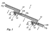
- Fig.1 shows solar roof tiles 1, which are laid on a roof structure 2.
- the roof truss 2 comprises roof battens 21 as well as load-bearing roof beams, not shown in the figures for the sake of clarity, on which the roof battens 21 are fastened.
- the solar roof tiles 1 lie with their head-side portion on the roof battens 21 and with their foot-side portion on top of the head-side portion of eaves side adjacent solar roof tile 1.
- the solar roof tile 1 has a ceramic base body 11, which in the in Fig. 1 shown
- Embodiment is shown only schematically.
- the solar roof tiles arranged on the roof truss 2 form a roof covering 3.
- a photoactive cell 12 for electric power generation is arranged on top of the center portion and the foot portion of the solar roof tile 1.
- the photoactive cell 12 is preferably formed as a dye cell and applied as a photoactive layer 12 p directly on the ceramic base body 11.
- the photoactive cell 12 formed as a dye cell preferably has an optically transparent and electrically conductive coating comprising a crystalline tungsten-doped tin oxide.
- a coating or glaze 12b is applied, which completely covers the photoactive layer 12p.
- electrical conductors 11l are arranged in order to produce an electrical connection between the photoactive layer 11p on the one hand and an electrical connecting device 13 arranged on the underside of the main body 11 in the head region, which has two electrical contact elements 13k insulated from one another (see FIGS. 2 and 3 ).
- the electrical connection device 13 is formed integrally with the ceramic base body 11.
- FIGS. 2 and 3 show the structure of the electrical connection device 13 in detail.
- connecting device 13 is formed as an insulation displacement member having two cutting edges for contacting an electrical conductor.
- the cutting edges are formed on contact elements 13k, wherein the contact elements 13k are arranged to form a distance space mirror images of each other and are electrically insulated from each other by a space filling the plate-shaped insulating 13i.
- the contact elements 13k protrude from the inner end face of the connecting device 13 at an angle of 90 °, which in on the Roof chair 2 laid solar roof tile 1 rests on the ridge-side end of the roof batten 21.
- the contact elements 13k engage in laid on the roof truss 2 solar roof tiles 1 in a busbar 22, which is arranged in a formed in the ridge-side end side of the roof batten 21 groove.
- the bus bar 22 includes in the in Fig. 1 and 2 illustrated embodiment, a base body 22g of an electrical insulating material and electrical contact elements 22k, which are embedded in the base body 22g.
- the electrical insulating material may be, for example, an elastic plastic that can be cut by the electrical contact elements 22k.
- the contact elements 13k of the electrical connection device 13 cut through the base body 22g and thus come into electrical contact with the electrical contact elements 22k embedded in the base body 22g. Because the cutting edges of the contact elements jump back on a foot-side section of the contact elements 13k, the contact elements 13k are positively connected to the busbar 22 and secured against being pulled out of the busbar 22.
- the contact elements 13k of the arranged on the solar roof tiles 1 electrical connection device 13 are designed as resilient plug-in elements, and arranged on the busbar 22 contact elements 22k formed as sockets in which the plug-in elements intervened in the roof truss 2 laid solar roof tile 1.
- FIGS. 4 to 7 show further embodiments, wherein the Fig. 4 analogous to Fig. 1 on the attic 2 laid solar roof tiles 1 shows.
- the roof truss 2 comprises load-bearing roof beams and roof battens 21 arranged on them FIGS. 4 to 7 the roof beams, which carry the roof battens 21, not shown for the sake of clarity.
- a first electrical connection device 13 is disposed on the underside of the foot-side portion of the solar roof tile 1 and engages in one at the top of the Head side portion of a eaves side adjacent solar roof tile 1 arranged second connection device 14 a.
- the photoactive cells 12 of adjacent solar roof tiles 1 are connected in a series connection.
- the connection devices 13 and 14 are formed in one pole.
- the ceramic base body 11 has a drip nose 11t for discharging water in the region of the connection device 13.
- FIG. 5 illustrated embodiment is analogous to that in Fig. 2 illustrated embodiment, with the difference that the electrical contact elements 13k and 14k are each arranged perpendicular to the bottom or to the top of the solar roof tile 1.
- the electrical contact element 13k of the first electrical connection device 13 is integrally formed with two cutting edges.
- the second connection device 14 corresponds in structure to the in Fig. 1 and 2 bus bar 22 described above.
- the contact element 13k of the first electrical connection device 13 is formed as an insulation displacement member having a cutting fork, wherein the two cutting edges are arranged opposite to each other and limit an insulation displacement gap.
- the second electrical connection device 14 has a wire-shaped electrical contact element 14k which engages in the cutting gap of the fork-shaped contact element 13k when the solar roof tile 1 is laid on the roof structure 2.
- FIG. 7 illustrated embodiment is analogous to that in Fig. 3 formed embodiment, wherein the electrical contact element 13k of the first connection device 13 is formed as a resilient plug-in element, and the electrical contact element 14k of the second electrical connection device 14 is formed as a socket into which the plug element engages when laid on the roof truss 2 solar roof tile 1.
Landscapes
- Engineering & Computer Science (AREA)
- Architecture (AREA)
- Civil Engineering (AREA)
- Structural Engineering (AREA)
- Roof Covering Using Slabs Or Stiff Sheets (AREA)
- Photovoltaic Devices (AREA)
Abstract
Description
- Die Erfindung betrifft einen Solardachziegel nach den Merkmalen des Oberbegriffs des Anspruchs 1.
- Die
DE 103 58 851 A1 beschreibt einen Photovoltaikdachziegel mit einem Grundkörper, auf dessen Oberfläche eine Glasurschicht aufgebracht ist, die das Substrat eines photovoltaischen Elements ist. Es sind ein fußseitiges und ein kopfseitiges Kontaktelement vorgesehen, die aus Endabschnitten von Leiterbahnen ausgebildet sind. Bei in der Dachabdeckung verlegten Photovoltaikziegeln kommt das kopfseitige Kontaktelement eines unteren Photovoltaikziegels mit dem fußseitigen Kontaktelement des in der nächsthöheren Ziegelreihe angrenzenden Nachbarziegels zur Anlage, so dass die zugehörigen Leiterbahnen elektrisch miteinander verbunden sind. Die gegenseitige Kontaktierung benachbarter Ziegel kann auch an den Seitenfalzen erfolgen. - Die
EP 2 398 059 A1 beschreibt einen Dachziegel mit einer Solarzellenfolie. Zur Kontaktierung sind winkelförmige Kontaktelemente mit Schneidelementen vorgesehen, die bei der Montage des Dachziegels in einer Dacheindeckung eine Isolierschicht eines an einer Dachlatte angeordneten zweipoligen Kontaktelements durchgreifen. Die Schneidelemente sind gegenüber den Kontaktelementen elektrisch isoliert und jeweils mit einer Ableitung der Solarzellenfolie elektrisch verbunden. - Die Aufgabe der Erfindung ist, einen Solardachziegel der genannten Art, der eine verbesserte elektrische Kontaktierung aufweist, sowie eine verbesserte Dachkonstruktion mit Solardachziegeln anzugeben.
- Die Aufgabe der Erfindung wird mit einem Solardachziegel mit den Merkmalen des Anspruchs 1 gelöst.
- Der erfindungsgemäße Solardachziegel weist einen keramischen Grundkörper auf, auf dessen Außenseite eine photoaktive Zelle zur elektrischen Stromgewinnung angeordnet ist. Weiter mit einer Anschlussvorrichtung, die ein elektrisches Kontaktelement aufweist, welches mit einer Anschlussvorrichtung eines zweiten Solardachziegels und/oder mit einem elektrischen Leiter und/oder mit einer Stromschiene verbindbar ist. Wobei das elektrische Kontaktelement so ausgebildet ist, dass es sich beim Auflegen des Solardachziegels auf eine Unterkonstruktion automatisch mit einer Stromschiene und/oder einer Anschlussvorrichtung eines zweiten Solardachziegels und/oder einem elektrischen Leiter der Unterkonstruktion verbindet, wobei vorgesehen ist, dass die Anschlussvorrichtung einen elektrischen Leiter aufweist, der zumindest abschnittsweise als eine optisch transparente und elektrisch leitfähige Beschichtung ausgebildet oder mit einer optisch transparenten und elektrisch leitfähigen Beschichtung verbunden ist.
- Über die zumindest abschnittsweise optisch transparente Beschichtung des elektrischen Leiters wird insbesondere im Bereich der photoaktiven Zelle eine besonders effiziente Art der Kontaktierung erzielt. Die optisch transparente Beschichtung des elektrischen Leiters kann im Bereich der photoaktiven Zelle angeordnet sein oder im Bereich der photoaktiven Zelle verlaufen, vorzugsweise um diese elektrisch zu kontaktieren. Die optisch transparente Beschichtung kann einen Bereich der photoaktiven Zelle teilweise überdecken. So kann eine flächige Kontaktierung der photoaktiven Zelle erzielt werden. Die flächige Kontaktierung ist für die Stromableitung besonders vorteilhaft, da nur eine geringe Strombelastung pro Flächeneinheit auftritt. Zudem wird verhindert, dass der für die Stromgewinnung wirksame photoaktive Bereich der Zelle durch die Kontaktierung eingeschränkt wird bzw. die wirksame photoaktive Fläche der Zelle verkleinert wird.
- Eine mechanisch besonders widerstandsfähige und abriebfeste Beschichtung, die zugleich eine hohe optische Transparenz besitzt, kann erzielt werden, wenn die optisch transparente und elektrisch leitfähige Beschichtung ein Metalloxid, insbesondere ein Zinnoxid enthält. Das Zinnoxid kann zudem mit weiteren Metallen, beispielsweise mit Wolfram oder Indium oder Antimon dotiert werden um die mechanische Widerstandsfähigkeit der Beschichtung weiter zu verbessern. Auch eine Dotierung des Zinnoxids mit Fluor ist denkbar.
- Es kann vorgesehen sein, dass die Verbindung des elektrischen Kontaktelements des Solardachziegels mit einer Stromschiene und/oder einer Anschlussvorrichtung eines zweiten Solardachziegels und/oder einem elektrischen Leiter kraftschlüssig oder formschlüssig erfolgt. Dadurch wird eine elektrische Verbindung erreicht, die mechanisch stabil ist und gleichzeitig eine hohe Kontaktsicherheit aufweist.
- Die photoaktive Zelle kann beispielsweise als Solarzelle, insbesondere als Siliziumzelle oder als Dünnschichtzelle oder als organische Solarzelle ausgebildet sein. Für eine Ausführung mit niedrigen Herstellkosten kann die photoaktive Zelle als Grätzelzelle oder als Farbstoffzelle ausgebildet sein.
- In einer Ausführung kann vorgesehen sein, dass das elektrische Kontaktelement an der Innenseite des keramischen Grundkörpers angeordnet ist und vorzugsweise in dem keramischen Grundkörper gehaltert ist.
- Das elektrische Kontaktelement kann einen eine Kontaktfeder aufweisenden Stift aufweisen, der beim Auflegen des Solardachziegels auf eine Unterkonstruktion in die Stromschiene oder eine Anschlussvorrichtung eines zweiten Solarziegels formschlüssig eingreift.
- In einer vorteilhaften Ausbildung kann vorgesehen sein, dass das elektrische Kontaktelement als Schneidklemmelement ausgebildet ist, welches zwei Schneidflanken zum Kontaktieren eines elektrischen Leiters aufweist.
- Das Schneidklemmelement kann eine Schneidgabel aufweisen, wobei die zwei Schneidflanken einander gegenüberliegend angeordnet sind und einen Schneidklemmspalt begrenzen.
- Es kann auch vorgesehen sein, dass das Schneidklemmelement eine Schneidspitze aufweist, wobei die zwei Schneidflanken einander gegenüberliegend angeordnet sind und die Schneidspitze bilden, indem sie ausgehend von einer gemeinsamen Spitze zur Basis des Schneidklemmelementes hin mit größerem Abstand zueinander verlaufen.
- Die beiden Schneidflanken der Schneidspitze können voneinander elektrisch isoliert sein.
- Es kann vorgesehen sein, dass das Schneidklemmelement während des Kontaktierens eine Isolierung durchtrennt.
- Weiter kann vorgesehen sein, dass die Anschlussvorrichtung ein elektrisches Anschlusselement aufweist, welches an der Außenseite des keramischen Grundkörpers angeordnet und mit dem elektrischen Kontaktelement eines zweiten Solardachziegels verbindbar ist. Auf diese Weise können die photoaktiven Zellen benachbarter Solardachziegel in einer Reihenschaltung und/oder in einer Parallelschaltung elektrisch miteinander verbunden sein.
- Der keramische Grundkörper kann an seiner Innenseite eine Nase zum Einhängen an einen Dachstuhl oder eine Dachlatte aufweisen und es kann ein elektrisches Kontaktelement der Anschlussvorrichtung im Bereich dieser Nase angeordnet sein.
- Die photoaktive Zelle kann beispielsweise als Farbstoffzelle ausgebildet sein und als eine photoaktive Schicht direkt auf den keramischen Grundkörper aufgebracht oder mit dem keramischen Grundkörper flächig verbunden sein. So ergibt sich eine besonders kostengünstige Art der Herstellung.
- Vorzugsweise kann die optisch transparente und elektrisch leitfähige Beschichtung Wolfram-dotiertes Zinnoxid, vorzugsweise kristallines Wolfram-dotiertes Zinnoxid enthalten. Dadurch kann bei geringen Herstellungskosten eine mechanisch widerstandsfähige Beschichtung erzielt werden, die dennoch eine hohe elektrische Leitfähigkeit und eine gute optische Transparenz aufweist.
- Es kann vorgesehen sein, dass die Anschlussvorrichtung die optisch transparente und elektrisch leitfähige Beschichtung zur elektrischen Kontaktierung der photoaktiven Zelle und das elektrische Kontaktelement zur elektrischen Kontaktierung einer Stromschiene und/oder einer Anschlussvorrichtung eines zweiten Solardachziegels und/oder einem elektrischen Leiter einer Unterkonstruktion umfasst. Zudem kann die Anschlussvorrichtung einen Abschnitt mit elektrischen Leitern, vorzugsweise metallischen Leitern umfassen, um die optisch transparente und elektrisch leitfähige Beschichtung mit dem elektrischen Kontaktelement zu verbinden. Es ist vorgesehen, dass die elektrischen Leiter zumindest abschnittsweise innerhalb des keramischen Grundkörpers verlaufen um eine die eine elektrische Verbindung zwischen der optisch transparenten und elektrisch leitfähigen Beschichtung einerseits und der dem elektrischen Kontaktelement andererseits herstellen.
- Es kann vorgesehen sein, dass die elektrischen Leiter bei der Herstellung des Dachziegels in die grüne Keramik eingelegt oder eingepresst werden. Bei dem Berennvorgang des Solardachziegels verbinden sich die elektrischen Leiter mit dem keramischen Grundkörper.
- Auf die Außenseite des keramischen Grundkörpers kann eine Beschichtung oder Glasur aufgebracht sein, welche die photoaktive Schicht bzw. die photoaktive Zelle komplett abdeckt.
- Es kann vorgesehen sein, dass der keramische Grundkörper im Bereich einer Anschlussvorrichtung oder eines elektrischen Kontaktelements eine Tropfnase zum Abführen von Wasser aufweist.
- Gemäß einer bevorzugten Ausführungsform der Erfindung weist der Solardachziegel eine photokatalytisch aktive Oberflächenbeschichtung auf. Die photokatalytisch aktive Oberflächenbeschichtung kann dabei direkt auf der Photozelle, beispielsweise Grätzelzelle oder Farbstoffzelle, angeordnet oder aufgebracht sein. Gemäß einer weiteren Ausführungsform der Erfindung kann die photokatalytisch aktive Oberflächenbeschichtung auch über oder auf einer auf der Außenseite des keramischen Grundkörpers aufgebrachten Beschichtung oder Glasur angeordnet oder aufgebracht sein. Mithin kann auf der Photozelle beispielsweise zunächst eine Glasur oder erste Beschichtung und sodann eine photokatalytisch aktive Beschichtung angeordnet oder aufgebracht sein.
- Die photokatalytisch aktive Oberflächenbeschichtung enthält vorzugsweise photokatalytisch aktive, oxidkeramische Materialien, die vorzugsweise aus der Gruppe, die aus TiO2, Al2O3, SiO2, Ce2O3 und Mischungen davon besteht, ausgewählt wird.
- Vorzugsweise umfasst die photokatalytisch aktive Oberflächenbeschichtung Titanoxid, weiter vorzugsweise Anatas.
- Die photokatalytisch aktive Oberflächenbeschichtung ist vorzugsweise eine für sichtbares Licht transparente Beschichtung. Die Photokatalyse wird durch das im Sonnenlicht vorhandene UV-Licht induziert. Im Ergebnis werden auf dem Solarziegel vorhandene organische Materialien zersetzt, beispielsweise durch photokatalytisch erzeugte Sauerstoffradikale und/oder Hydroxylradikale. Die erzeugten Radikalspezies oxidieren beispielsweise sich auf den Solardachziegeln abgelagerte Verschmutzungsstoffe wie beispielsweise Pilzhyphen und/oder abgelagerten Schimmel, Pflanzenwuchs, wie Moos, Algen, etc., und/oder bakterielle Verunreinigungen.
- Durch die Anordnung oder Aufbringung einer photokatalytisch aktiven Beschichtung, vorzugsweise als äußerste Beschichtung oder Schicht, auf dem Solardachziegel kann einer Beeinträchtigung der Stromgewinnung durch dauerhafte Ablagerung von Verschmutzungsstoffen auf der Photozelle, vorzugsweise Grätzelzelle oder Farbstoffzelle, entgegengewirkt werden.
- Vorzugsweise wird als photokatalytisch aktive Beschichtung eine poröse Schicht aufgebracht, die bevorzugt im Wesentlichen eine oxidkeramische Schicht ist. Vorzugsweise enthält die Schicht Titanoxid, weiter bevorzugt Titandioxid, noch weiter bevorzugt Anatas. Die poröse Schicht kann dabei eine spezifische Oberfläche im Bereich von etwa 25 m2/g bis etwa 200 m2/g, weiter bevorzugt im Bereich von etwa 40 m2/g bis etwa 150 m2/g, noch weiter bevorzugt im Bereich von etwa 50 m2/g bis etwa 100 m2/g, aufweisen.
- Die mittlere Schichtdicke der photokatalytisch aktiven Schicht liegt vorzugsweise in einem Bereich von etwa 50 nm bis etwa 50 µm, weiter bevorzugt von etwa 100 nm, bis etwa 1 µm.
- Die photokatalytisch aktive Beschichtung oder Schicht umfasst vorzugsweise Mischungen aus Titandioxid und Siliziumdioxid, Titandioxid und Aluminiumoxid, Aluminiumoxid und Siliziumdioxid, oder Titandioxid und Siliciumdioxid und Aluminiumoxid oder besteht aus einer der vorgenannten Mischungen.
- Vorzugsweise umfasst die photokatalytisch aktive Beschichtung oder Schicht Mischungen aus Titandioxid und Siliziumdioxid oder besteht daraus. Gemäß einer weiteren bevorzugten Ausführungsform umfasst die photokatalytisch aktive Beschichtung oder Schicht Titandioxid, vorzugsweise in der Anatasmodifikation, das unter Verwendung von kolloidalem Siilziumdioxid an der Oberfläche des Solardachziegels gebunden ist.
- Der mit einer photokatalytischen Beschichtung oder Schicht versehene Solardachziegel ist mithin vorzugsweise selbstreinigend. Die unter Einwirkung von Photokatalyse oxidierten Verschmutzungsstoffe weisen ein signifikant verringertes Haftvermögen an dem Solardachziegel auf und werden beispielsweise bei Beregnung oder Berieselung abgewaschen.
- Darüber hinaus wirkt die aufgebrachte photokatalytisch aktive Beschichtung oder Schicht auch luftreinigend, indem in der Luft enthaltene Schadgase und /oder Schadstoff, wie beispielsweise NOx, SOx, NH3, Formaldehyd, Acetaldehyd, Toluol, etc., abgebaut werden und somit die umgebende Luft gereinigt wird. In diesem Zusammenhang wird auf die
EP 2 072 118 A2 verwiesen, deren Inhalt hiermit unter Bezugnahme aufgenommen wird. - Verfahren zur Herstellung von photokatalytisch aktiven Beschichtungen sind aus
WO 03/101912 A1 WO 03/101913 A1 EP 1 659 106 A2 bekannt, deren Inhalt hiermit unter Bezugnahme aufgenommen wird. - Die Aufgabe der Erfindung wird weiter mit einer Dachkonstruktion mit einem Dachstuhl gelöst, wobei vorgeschlagen wird, dass der Dachstuhl als Unterkonstruktion ausgebildet ist und mehrere erfindungsgemäße Solardachziegel trägt.
- Der Dachstuhl kann mehrere Dachlatten aufweist, die parallel und beabstandet zueinander verlaufen, wobei vorgesehen ist,
dass eine oder mehrere Dachlatten als mit der Anschlussvorrichtung verbindbare Stromschiene ausgebildet sind oder eine mit der Anschlussvorrichtung verbindbare Stromschiene aufweisen. - Wenigstens zwei Solardachziegel können elektrisch parallelgeschaltet sein, wobei beide Pole eines Solardachziegels über eine gemeinsame Stromschiene mit zwei getrennten elektrischen Leitern geführt sind.
- Es kann vorgesehen sein, dass wenigstens zwei einander zumindest teilweise überlappende Solardachziegel elektrisch in Serie geschaltet sind, indem eine Anschlussvorrichtung des ersten Solardachziegels direkt mit einer Anschlussvorrichtung des zweiten Solardachziegels verbunden ist. Eine Stromschiene kann zumindest einen in flexibles Isoliermaterial eingebetteten elektrischen Leiter aufweisen, so dass dieser in der Stromschiene quer zu seiner Längserstreckung beweglich gelagert ist.
- Die Erfindung wird nun anhand von Ausführungsbeispielen näher erläutert. Es zeigen
- Fig. 1
- eine Dachkonstruktion, gebildet aus einem ersten Ausführungsbeispiel des erfindungsgemäßen Solardachziegels in einer schematischen Schnittdarstellung;
- Fig. 2
- eine Detailschnittansicht des Solardachziegels in
Fig. 1 ; - Fig. 3
- eine Detailschnittansicht eines zweiten Ausführungsbeispiels eines erfindungsgemäßen Solardachziegels;
- Fig. 4
- eine Dachkonstruktion, gebildet aus einem dritten Ausführungsbeispiel des erfindungsgemäßen Solardachziegels in einer schematischen Schnittdarstellung;
- Fig. 5
- eine Detailschnittansicht des Solardachziegels in
Fig. 4 ; - Fig. 6
- eine Detailschnittansicht eines vierten Ausführungsbeispiels eines erfindungsgemäßen Solardachziegels;
- Fig. 7
- eine Detailschnittansicht eines fünften Ausführungsbeispiels eines erfindungsgemäßen Solardachziegels.
-
Fig.1 zeigt Solardachziegel 1, die auf einem Dachstuhl 2 verlegt sind. Der Dachstuhl 2 umfasst Dachlatten 21 sowie in den Figuren zugunsten der Übersichtlichkeit nicht dargestellte tragende Dachbalken, an denen die Dachlatten 21 befestigt sind. Die Solardachziegel 1 liegen mit ihrem kopfseitigen Abschnitt auf den Dachlatten 21 und mit ihrem fußseitigen Abschnitt auf der Oberseite des kopfseitigen Abschnitts des traufseitig benachbarten Solardachziegels 1 auf. Der Solardachziegel 1 weist einen keramischen Grundkörper 11 auf, der in dem inFig. 1 dargestellten - Ausführungsbeispiel nur schematisch dargestellt ist. Die auf dem Dachstuhl 2 angeordneten Solardachziegel bilden eine Dacheindeckung 3.
- Auf der Oberseite des Mittenabschnitts und des Fußabschnitts des Solardachziegels 1 ist eine photoaktive Zelle 12 zur elektrischen Stromgewinnung angeordnet. Die photoaktive Zelle 12 ist vorzugsweise als Farbstoffzelle ausgebildet und als eine photoaktive Schicht 12p direkt auf den keramischen Grundkörper 11 aufgebracht. Die als Farbstoffzelle ausgebildete photoaktive Zelle 12 weist vorzugsweise eine optisch transparente und elektrisch leitfähige Beschichtung auf, umfassend ein kristallines wolframdotiertes Zinnoxid.
- Auf die Außenseite des keramischen Grundkörpers 11 ist eine Beschichtung oder Glasur 12b aufgebracht, welche die photoaktive Schicht 12p komplett abdeckt.
- Innerhalb des keramischen Grundkörpers 11 sind elektrische Leiter 11l angeordnet, um eine elektrische Verbindung zwischen der photoaktiven Schicht 11 p einerseits und einer an der Unterseite des Grundkörpers 11 im Kopfbereich angeordneten elektrischen Anschlussvorrichtung 13 herzustellen, die zwei voneinander isolierte elektrische Kontaktelemente 13k aufweist (siehe
Fig. 2 und 3 ). In den inFig. 1 bis 3 dargestellten Ausführungsbeispielen ist die elektrische Anschlussvorrichtung 13 einstückig mit dem keramischen Grundkörper 11 ausgebildet. - Die
Fig. 2 und 3 zeigen den Aufbau der elektrischen Anschlussvorrichtung 13 im Einzelnen. - Die in
Fig. 1 und2 dargestellte Anschlussvorrichtung 13 ist als ein Schneidklemmelement ausgebildet, welches zwei Schneidflanken zum Kontaktieren eines elektrischen Leiters aufweist. Die Schneidflanken sind an Kontaktelementen 13k ausgebildet, wobei die Kontaktelemente 13k unter Ausbildung eines Abstandsraumes spiegelbildlich zueinander angeordnet sind und durch ein den Abstandsraum ausfüllendes plattenförmiges Isolierelement 13i elektrisch voneinander isoliert sind. Die Kontaktelemente 13k ragen aus der inneren Stirnseite der Anschlussvorrichtung 13 unter einem Winkel von 90° hervor, die bei auf dem Dachstuhl 2 verlegtem Solardachziegel 1 auf der firstseitigen Stirnseite der Dachlatte 21 aufliegt. - Die Kontaktelemente 13k greifen bei auf dem Dachstuhl 2 verlegtem Solardachziegel 1 in eine Stromschiene 22 ein, die in einer in der firstseitigen Stirnseite der Dachlatte 21 ausgebildeten Nut angeordnet ist. Die Stromschiene 22 umfasst in dem in
Fig. 1 und2 dargestellten Ausführungsbeispiel einen Grundkörper 22g aus einem elektrischen Isoliermaterial und elektrische Kontaktelemente 22k, die in den Grundkörper 22g eingebettet sind. Bei dem elektrischen Isoliermaterial kann es sich beispielsweise um einen elastischen Kunststoff handeln, der durch die elektrischen Kontaktelemente 22k schneidbar ist. Beim Aufsetzen des Solardachziegels 1 auf die Dachlatte 21 durchtrennen die Kontaktelemente 13k der elektrischen Anschlussvorrichtung 13 den Grundkörper 22g und gelangen so in elektrischen Kontakt mit den im Grundkörper 22g eingebetteten elektrischen Kontaktelementen 22k. Weil die Schneidflanken der Kontaktelemente an einem fußseitigen Abschnitt der Kontaktelemente 13k zurückspringen, sind die Kontaktelemente 13k mit der Stromschiene 22 formschlüssig verbunden und gegen Herausziehen aus der Stromschiene 22 gesichert. - In dem in
Fig. 3 dargestellten Ausführungsbeispiel sind die Kontaktelemente 13k der an dem Solardachziegel 1 angeordneten elektrischen Anschlussvorrichtung 13 als federnde Steckelemente ausgebildet, und die an der Stromschiene 22 angeordneten Kontaktelemente 22k als Buchsen ausgebildet, in welche die Steckelemente bei auf dem Dachstuhl 2 verlegtem Solardachziegel 1 eingreifen. - Die
Figuren 4 bis 7 zeigen weitere Ausführungsbeispiele, wobei dieFig. 4 analog zuFig. 1 auf dem Dachstuhl 2 verlegte Solardachziegel 1 zeigt. Der Dachstuhl 2 umfasst tragende Dachbalken und an diesen angeordnete Dachlatten 21. Wie bei den vorstehenden Figuren sind auch bei denFiguren 4 bis 7 die Dachbalken, welche die Dachlatten 21 tragen, zugunsten der Übersichtlichkeit nicht dargestellt. Im Unterschied zu dem inFig. 1 dargestellten Ausführungsbeispiel ist eine erste elektrische Anschlussvorrichtung 13 an der Unterseite des fußseitigen Abschnitts des Solardachziegels 1 angeordnet und greift in eine an der Oberseite des kopfseitigen Abschnitts eines traufseitig benachbarten Solardachziegels 1 angeordnete zweite Anschlussvorrichtung 14 ein. In den in denFig. 4 bis 7 dargestellten Ausführungsbeispielen sind die photoaktiven Zellen 12 benachbarter Solardachziegel 1 in einer Reihenschaltung verbunden. Im Unterschied zu den vorstehend beschriebenen Ausführungsbeispielen sind die Anschlussvorrichtungen 13 und 14 einpolig ausgebildet. Der keramische Grundkörper 11 weist im Bereich der Anschlussvorrichtung 13 eine Tropfnase 11t zum Abführen von Wasser auf. - Das in
Fig. 5 dargestellte Ausführungsbeispiel ist analog zu dem inFig. 2 dargestellten Ausführungsbeispiel ausgebildet, mit dem Unterschied, dass die elektrischen Kontaktelemente 13k bzw. 14k jeweils senkrecht zu der Unterseite bzw. zu der Oberseite des Solardachziegels 1 angeordnet sind. Das elektrische Kontaktelement 13k der ersten elektrischen Anschlussvorrichtung 13 ist mit zwei Schneidflanken einstückig ausgebildet. Die zweite Anschlussvorrichtung 14 entspricht im Aufbau der inFig. 1 und2 weiter oben beschriebenen Stromschiene 22. - In dem in
Fig. 6 dargestellten Ausführungsbeispiel ist das Kontaktelement 13k der ersten elektrischen Anschlussvorrichtung 13 als ein Schneidklemmelement ausgebildet, das eine Schneidgabel aufweist, wobei die zwei Schneidflanken einander gegenüberliegend angeordnet sind und einen Schneidklemmspalt begrenzen. Die zweite elektrische Anschlussvorrichtung 14 weist ein drahtförmiges elektrisches Kontaktelement 14k auf, das bei auf dem Dachstuhl 2 verlegtem Solardachziegel 1 in den Schneidspalt des gabelförmigen Kontaktelements 13k eingreift. - Das in
Fig. 7 dargestellte Ausführungsbeispiel ist analog zu dem inFig. 3 dargestellten Ausführungsbeispiel ausgebildet, wobei das elektrische Kontaktelement 13k der ersten Anschlussvorrichtung 13 als federndes Steckelement ausgebildet ist, und das elektrische Kontaktelement 14k der zweiten elektrischen Anschlussvorrichtung 14 als Buchse ausgebildet ist, in welche das Steckelement bei auf dem Dachstuhl 2 verlegtem Solardachziegel 1 eingreift. -
- 1
- Solardachziegel
- 2
- Dachstuhl
- 3
- Dacheindeckung
- 11
- keramischer Grundkörper
- 11l
- elektrischer Leiter
- 11t
- Tropfnase
- 12
- photoaktive Zelle
- 12b
- Beschichtung; Glasur
- 12p
- photoaktive Schicht
- 13
- elektrische Anschlussvorrichtung; erste elektrische Anschlussvorrichtung
- 13i
- Isolierelement
- 13k
- elektrisches Kontaktelement
- 14
- elektrische Anschlussvorrichtung
- 14i
- Isolierelement
- 14k
- elektrisches Kontaktelement
- 21
- Dachlatte
- 22
- Stromschiene
- 22g
- Grundkörper
- 22k
- Kontaktelement
Claims (24)
- Solardachziegel (1) mit einem keramischen Grundkörper (11), auf dessen Außenseite eine photoaktive Zelle (12) zur elektrischen Stromgewinnung angeordnet ist, mit einer Anschlussvorrichtung (13), die ein mit der photoaktiven Zelle (12) elektrisch leitend verbundenes Kontaktelement (13k) aufweist, welches mit einer Anschlussvorrichtung (14) eines zweiten Solardachziegels (1) und/oder mit einem elektrischen Leiter und/oder mit einer Stromschiene (22) verbindbar ist, indem das elektrische Kontaktelement (13) so ausgebildet ist, dass sich beim Auflegen des Solardachziegels auf eine Unterkonstruktion ein elektrisch leitender Abschnitt des elektrischen Kontaktelements (13) automatisch mit einer elektrisch leitenden Stromschiene (22) und/oder mit einem elektrisch leitenden Teil einer Anschlussvorrichtung (14) eines zweiten Solardachziegels und/oder mit einem an der Unterkonstruktion angeordneten elektrischen Leiter verbindet,
dadurch gekennzeichnet,
dass die Anschlussvorrichtung (14) einen elektrischen Leiter aufweist, der zumindest abschnittsweise als eine optisch transparente und elektrisch leitfähige Beschichtung ausgebildet ist oder mit einer optisch transparenten und elektrisch leitfähigen Beschichtung verbunden ist. - Solardachziegel nach Anspruch 1,
dadurch gekennzeichnet,
dass die optisch transparente und elektrisch leitfähige Beschichtung ein Metalloxid, insbesondere ein Zinnoxid enthält. - Solardachziegel nach Anspruch 1 oder 2,
dadurch gekennzeichnet,
dass die optisch transparente und elektrisch leitfähige Beschichtung im Bereich der photoaktiven Zelle (12) angeordnet ist und/oder die photoaktive Zelle (12) elektrisch kontaktiert. - Solardachziegel nach einem der Ansprüche 1 bis 3,
dadurch gekennzeichnet,
dass das elektrische Kontaktelement (13) an der Innenseite des keramischen Grundkörpers (11) angeordnet ist und vorzugsweise in dem keramischen Grundkörper (11) gehaltert ist. - Solardachziegel nach einem der vorhergehenden Ansprüche,
dadurch gekennzeichnet,
dass das elektrische Kontaktelement (13k, 14k) einen eine Kontaktfeder aufweisenden Stift aufweist, der beim Auflegen des Solardachziegels (1) auf eine Unterkonstruktion in die Stromschiene (22) oder eine Anschlussvorrichtung (14) eines zweiten Solarziegels (1) eingreift, wobei die Kontaktfeder Toleranzen ausgleicht. - Solardachziegel nach einem der Ansprüche 1 bis 4,
dadurch gekennzeichnet,
dass das elektrische Kontaktelement (13k, 14k) als Schneidklemmelement ausgebildet ist, welches zwei Schneidflanken zum Kontaktieren eines elektrischen Leiters aufweist. - Solardachziegel nach Anspruch 6,
dadurch gekennzeichnet,
dass das Schneidklemmelement eine Schneidgabel aufweist, wobei die zwei Schneidflanken einander gegenüberliegend angeordnet sind und einen Schneidklemmspalt begrenzen. - Solardachziegel nach Anspruch 6,
dadurch gekennzeichnet,
dass das Schneidklemmelement eine Schneidspitze aufweist, wobei die zwei Schneidflanken einander gegenüberliegend angeordnet sind und die Schneidspitze bilden, indem sie ausgehend von einer gemeinsamen Spitze zur Basis des Schneidklemmelementes hin mit größerem Abstand zueinander verlaufen. - Solardachziegel nach Anspruch 8,
dadurch gekennzeichnet,
dass die beiden Schneidflanken der Schneidspitze voneinander elektrisch isoliert sind. - Solardachziegel nach einem der Ansprüche 6 bis 9,
dadurch gekennzeichnet,
dass das Schneidklemmelement während des Kontaktierens eine Isolierung durchtrennt. - Solardachziegel nach einem der vorhergehenden Ansprüche,
dadurch gekennzeichnet,
dass die Anschlussvorrichtung (14) ein elektrisches Anschlusselement (14k) aufweist, welches an der Außenseite des keramischen Grundkörpers (11) angeordnet und mit dem elektrischen Kontaktelement (13) eines zweiten Solardachziegels (1) verbindbar ist. - Solardachziegel nach einem der vorhergehenden Ansprüche,
dadurch gekennzeichnet,
dass der keramische Grundkörper (1) an seiner Innenseite eine Nase zum Einhängen an einen Dachstuhl oder eine Dachlatte (21) aufweist und ein elektrisches Kontaktelement (13k) der Anschlussvorrichtung (13) im Bereich dieser Nase angeordnet ist. - Solardachziegel nach einem der vorhergehenden Ansprüche,
dadurch gekennzeichnet,
dass die photoaktive Zelle (12) auf die Außenseite des keramischen Grundkörper (11) aufgebracht oder mit der Außenseite des keramischen Grundkörper (11) flächig verbunden ist. - Solardachziegel nach einem der vorhergehenden Ansprüche,
dadurch gekennzeichnet,
dass die photoaktive Zelle (12) als Grätzelzelle oder als Farbstoffzelle ausgebildet ist und die optisch transparente und elektrisch leitfähige Beschichtung Wolfram-dotiertes Zinnoxid, vorzugsweise kristallines enthält. - Solardachziegel nach einem der vorhergehenden Ansprüche,
dadurch gekennzeichnet,
dass die Anschlussvorrichtung (13, 14) innerhalb des keramischen Grundkörpers (11) verlaufende elektrische Leiter (11l) umfasst, die eine elektrische Verbindung zwischen der optisch transparenten und elektrisch leitfähigen Beschichtung einerseits und dem elektrischen Kontaktelement (13k, 14k, 22k) andererseits herstellen. - Solardachziegel nach einem der vorhergehenden Ansprüche,
dadurch gekennzeichnet,
dass auf die Außenseite des keramischen Grundkörpers (11) eine Beschichtung oder Glasur aufgebracht ist, welche die photoaktive Zelle (12) komplett abdeckt. - Solardachziegel nach einem der vorhergehenden Ansprüche,
dadurch gekennzeichnet,
dass der keramische Grundkörper (11) im Bereich einer Anschlussvorrichtung (13) oder eines elektrischen Kontaktelements (14k) eine Tropfnase (11t) zum Abführen von Wasser aufweist. - Solardachziegel nach einem der vorhergehenden Ansprüche,
dadurch gekennzeichnet,
dass der Solardachziegel eine photokatalytisch aktive Oberflächenbeschichtung aufweist. - Solardachziegel nach Anspruch 18,
dadurch gekennzeichnet,
dass die photokatalytisch aktive Oberflächenbeschichtung Titanoxid, vorzugsweise Anatas, umfasst. - Dachkonstruktion mit einem Dachstuhl,
dadurch gekennzeichnet,
dass der Dachstuhl (2) als Unterkonstruktion ausgebildet ist und mehrere Solardachziegel (1) nach einem der vorhergehenden Ansprüche trägt. - Dachkonstruktion nach Anspruch 20,
wobei der Dachstuhl (2) mehrere Dachlatten (21) aufweist, die parallel und beabstandet zueinander verlaufen,
dadurch gekennzeichnet,
dass eine oder mehrere Dachlatten (21) als mit der Anschlussvorrichtung (13) verbindbare Stromschiene (22) ausgebildet sind oder eine mit der Anschlussvorrichtung (13) verbindbare Stromschiene (22) aufweisen. - Dachkonstruktion nach Anspruch 20 oder 21,
dadurch gekennzeichnet,
dass wenigstens zwei Solardachziegel (1) elektrisch parallelgeschaltet sind, wobei beide Pole eines Solardachziegels (1) über eine gemeinsame Stromschiene (22) mit zwei getrennten elektrischen Leitern geführt sind. - Dachkonstruktion nach Anspruch 20 oder 21,
dadurch gekennzeichnet,
dass wenigstens zwei einander zumindest teilweise überlappende Solardachziegel (1) elektrisch in Serie geschaltet sind, indem eine Anschlussvorrichtung (13) des ersten Solardachziegels (1) direkt mit einer Anschlussvorrichtung (14) des zweiten Solardachziegels (2) verbunden ist. - Dachkonstruktion nach einem der Ansprüche 20 bis 23,
dadurch gekennzeichnet,
dass eine Stromschiene (22) zumindest einen in flexibles Isoliermaterial eingebetteten elektrischen Leiter (22k) aufweist, so dass dieser in der Stromschiene (22) quer zu seiner Längserstreckung beweglich gelagert ist.
Priority Applications (5)
| Application Number | Priority Date | Filing Date | Title |
|---|---|---|---|
| SI201431454T SI2975760T1 (sl) | 2014-07-18 | 2014-07-18 | Solarni strešnik |
| PL14177716T PL2975760T3 (pl) | 2014-07-18 | 2014-07-18 | Dachówka solarna |
| DK14177716.9T DK2975760T3 (da) | 2014-07-18 | 2014-07-18 | Solcelletagsten |
| ES14177716T ES2763967T3 (es) | 2014-07-18 | 2014-07-18 | Teja solar |
| EP14177716.9A EP2975760B1 (de) | 2014-07-18 | 2014-07-18 | Solardachziegel |
Applications Claiming Priority (1)
| Application Number | Priority Date | Filing Date | Title |
|---|---|---|---|
| EP14177716.9A EP2975760B1 (de) | 2014-07-18 | 2014-07-18 | Solardachziegel |
Publications (2)
| Publication Number | Publication Date |
|---|---|
| EP2975760A1 true EP2975760A1 (de) | 2016-01-20 |
| EP2975760B1 EP2975760B1 (de) | 2019-10-30 |
Family
ID=51210348
Family Applications (1)
| Application Number | Title | Priority Date | Filing Date |
|---|---|---|---|
| EP14177716.9A Active EP2975760B1 (de) | 2014-07-18 | 2014-07-18 | Solardachziegel |
Country Status (5)
| Country | Link |
|---|---|
| EP (1) | EP2975760B1 (de) |
| DK (1) | DK2975760T3 (de) |
| ES (1) | ES2763967T3 (de) |
| PL (1) | PL2975760T3 (de) |
| SI (1) | SI2975760T1 (de) |
Cited By (1)
| Publication number | Priority date | Publication date | Assignee | Title |
|---|---|---|---|---|
| EP3648339A1 (de) * | 2018-11-02 | 2020-05-06 | Meto-Fer Automation AG | Solardachziegel und solardachabdeckung |
Citations (9)
| Publication number | Priority date | Publication date | Assignee | Title |
|---|---|---|---|---|
| WO2003101912A1 (de) | 2002-05-29 | 2003-12-11 | Erlus Aktiengesellschaft | Keramischer formkörper mit photokatalytischer beschichtung und verfharen zur herstellung desselben |
| DE10358851A1 (de) | 2002-12-23 | 2005-01-13 | Walther Dachziegel Gmbh | Photovoltaikdachziegel |
| EP1659106A2 (de) | 2004-11-17 | 2006-05-24 | Erlus Aktiengesellschaft | Keramischer Formkörper mit photokatalytisch-aktiver Beschichtung und Verfahren zur Herstellung desselben |
| FR2914785A1 (fr) * | 2007-04-06 | 2008-10-10 | Saint Gobain Ct Recherches | Revetement de toiture photovoltaique |
| WO2009071956A2 (en) * | 2007-12-03 | 2009-06-11 | Toth Miklos | Electric power generating solar roof tile and a procedure for its production |
| EP2072118A2 (de) | 2007-11-16 | 2009-06-24 | Erlus Aktiengesellschaft | Keramischer Formkörper mit einer photokatalytisch aktiven, luftreinigenden, transparenten Oberflächenbeschichtung und Verfahren zur Herstellung desselben |
| US20100223864A1 (en) * | 2009-03-06 | 2010-09-09 | Paul Dube | Wireless solar shingle panel and a method for implementing same |
| EP2398059A1 (de) | 2010-06-18 | 2011-12-21 | Grimme | Dachziegel ausgerüstet mit Solarzellen |
| US20120006397A1 (en) * | 2010-07-07 | 2012-01-12 | Hon Hai Precision Industry Co., Ltd. | Integrated solar roof tile and method for producing the same |
-
2014
- 2014-07-18 EP EP14177716.9A patent/EP2975760B1/de active Active
- 2014-07-18 SI SI201431454T patent/SI2975760T1/sl unknown
- 2014-07-18 ES ES14177716T patent/ES2763967T3/es active Active
- 2014-07-18 DK DK14177716.9T patent/DK2975760T3/da active
- 2014-07-18 PL PL14177716T patent/PL2975760T3/pl unknown
Patent Citations (10)
| Publication number | Priority date | Publication date | Assignee | Title |
|---|---|---|---|---|
| WO2003101912A1 (de) | 2002-05-29 | 2003-12-11 | Erlus Aktiengesellschaft | Keramischer formkörper mit photokatalytischer beschichtung und verfharen zur herstellung desselben |
| WO2003101913A1 (de) | 2002-05-29 | 2003-12-11 | Erlus Aktiengesellschaft | Keramischer formkörper mit photokatalytischer beschichtung und verfahren zur herstellung desselben |
| DE10358851A1 (de) | 2002-12-23 | 2005-01-13 | Walther Dachziegel Gmbh | Photovoltaikdachziegel |
| EP1659106A2 (de) | 2004-11-17 | 2006-05-24 | Erlus Aktiengesellschaft | Keramischer Formkörper mit photokatalytisch-aktiver Beschichtung und Verfahren zur Herstellung desselben |
| FR2914785A1 (fr) * | 2007-04-06 | 2008-10-10 | Saint Gobain Ct Recherches | Revetement de toiture photovoltaique |
| EP2072118A2 (de) | 2007-11-16 | 2009-06-24 | Erlus Aktiengesellschaft | Keramischer Formkörper mit einer photokatalytisch aktiven, luftreinigenden, transparenten Oberflächenbeschichtung und Verfahren zur Herstellung desselben |
| WO2009071956A2 (en) * | 2007-12-03 | 2009-06-11 | Toth Miklos | Electric power generating solar roof tile and a procedure for its production |
| US20100223864A1 (en) * | 2009-03-06 | 2010-09-09 | Paul Dube | Wireless solar shingle panel and a method for implementing same |
| EP2398059A1 (de) | 2010-06-18 | 2011-12-21 | Grimme | Dachziegel ausgerüstet mit Solarzellen |
| US20120006397A1 (en) * | 2010-07-07 | 2012-01-12 | Hon Hai Precision Industry Co., Ltd. | Integrated solar roof tile and method for producing the same |
Cited By (2)
| Publication number | Priority date | Publication date | Assignee | Title |
|---|---|---|---|---|
| EP3648339A1 (de) * | 2018-11-02 | 2020-05-06 | Meto-Fer Automation AG | Solardachziegel und solardachabdeckung |
| WO2020087188A1 (de) * | 2018-11-02 | 2020-05-07 | Meto-Fer Automation Ag | Solardachziegel und solardachabdeckung |
Also Published As
| Publication number | Publication date |
|---|---|
| SI2975760T1 (sl) | 2020-06-30 |
| EP2975760B1 (de) | 2019-10-30 |
| DK2975760T3 (da) | 2020-02-03 |
| PL2975760T3 (pl) | 2020-05-18 |
| ES2763967T3 (es) | 2020-06-01 |
Similar Documents
| Publication | Publication Date | Title |
|---|---|---|
| EP2537065B1 (de) | Elektrochrome verglasung mit seriell verschalteten zellen, sowie herstellungsverfahren hierfür | |
| EP1153439A1 (de) | Diodenstruktur, insbesondere für dünnfilmsolarzellen | |
| WO2006089770A1 (de) | Dach- oder fassadenverkleidung | |
| EP3132656B2 (de) | Transparente scheibe mit heizbeschichtung | |
| DE69201930T2 (de) | Anschluss von Verglasungen mit einer elektrisch leitfähigen Schicht. | |
| AT12996U1 (de) | Photovoltaisches modul und verwendung desselben | |
| EP0440869A1 (de) | Photovoltaisches Bauelement zur Umwandlung des Sonnenlichts in elektrischen Strom und photoelektrische Batterie | |
| EP2179426A2 (de) | Mehrschichtsystem mit kontaktelementen und verfahren zum erstellen eines kontaktelements für ein mehrschichtsystem | |
| EP2018644A2 (de) | Photovoltaische zelle | |
| WO2014009491A1 (de) | Kantenverbinder für photovoltaische solarmodule | |
| DE102009022745A1 (de) | Gebäudeelement, Gebäudehülle und Gebäude | |
| EP4183970A2 (de) | Stromabführungssystem für eine beschattungseinrichtung und beschattungseinrichtung hierfür | |
| EP2421053A2 (de) | Himmelsrichtungsverdrehter Freiflächenphotovoltaikgenerator | |
| EP2975760B1 (de) | Solardachziegel | |
| DE4138514C2 (de) | Montageelement für ein Vogelabwehrsystem | |
| DE3511082A1 (de) | Solarzelle | |
| DE102017214347B4 (de) | Verfahren zur Herstellung eines Fassadenelements sowie Fassadenelement | |
| DE10358851A1 (de) | Photovoltaikdachziegel | |
| DE10046134A1 (de) | Dach- und Fassadenschindel | |
| DE10020429A1 (de) | Dachelement mit integrierter Solarzelle | |
| WO2018130726A1 (de) | Baukastensystem mit einem bauelement und einem integrierten photovoltaischen element | |
| DE102013002113B4 (de) | Photovoltaikmodul mit einem streifenförmigen Element aus Kupfer zur Bildung fungizider und bakterizider Substanzen | |
| DE202008008743U1 (de) | Photovoltaisches Solarmodul | |
| EP3648339B1 (de) | Solardachabdeckung | |
| DE20023094U1 (de) | Dach- und Fassadenschindel |
Legal Events
| Date | Code | Title | Description |
|---|---|---|---|
| PUAI | Public reference made under article 153(3) epc to a published international application that has entered the european phase |
Free format text: ORIGINAL CODE: 0009012 |
|
| AK | Designated contracting states |
Kind code of ref document: A1 Designated state(s): AL AT BE BG CH CY CZ DE DK EE ES FI FR GB GR HR HU IE IS IT LI LT LU LV MC MK MT NL NO PL PT RO RS SE SI SK SM TR |
|
| AX | Request for extension of the european patent |
Extension state: BA ME |
|
| 17P | Request for examination filed |
Effective date: 20160531 |
|
| RAX | Requested extension states of the european patent have changed |
Extension state: BA Payment date: 20160531 Extension state: ME Payment date: 20160531 |
|
| RBV | Designated contracting states (corrected) |
Designated state(s): AL AT BE BG CH CY CZ DE DK EE ES FI FR GB GR HR HU IE IS IT LI LT LU LV MC MK MT NL NO PL PT RO RS SE SI SK SM TR |
|
| STAA | Information on the status of an ep patent application or granted ep patent |
Free format text: STATUS: EXAMINATION IS IN PROGRESS |
|
| 17Q | First examination report despatched |
Effective date: 20181109 |
|
| GRAP | Despatch of communication of intention to grant a patent |
Free format text: ORIGINAL CODE: EPIDOSNIGR1 |
|
| STAA | Information on the status of an ep patent application or granted ep patent |
Free format text: STATUS: GRANT OF PATENT IS INTENDED |
|
| GRAJ | Information related to disapproval of communication of intention to grant by the applicant or resumption of examination proceedings by the epo deleted |
Free format text: ORIGINAL CODE: EPIDOSDIGR1 |
|
| STAA | Information on the status of an ep patent application or granted ep patent |
Free format text: STATUS: EXAMINATION IS IN PROGRESS |
|
| INTG | Intention to grant announced |
Effective date: 20190528 |
|
| GRAP | Despatch of communication of intention to grant a patent |
Free format text: ORIGINAL CODE: EPIDOSNIGR1 |
|
| STAA | Information on the status of an ep patent application or granted ep patent |
Free format text: STATUS: GRANT OF PATENT IS INTENDED |
|
| INTC | Intention to grant announced (deleted) | ||
| INTG | Intention to grant announced |
Effective date: 20190709 |
|
| GRAS | Grant fee paid |
Free format text: ORIGINAL CODE: EPIDOSNIGR3 |
|
| RIN1 | Information on inventor provided before grant (corrected) |
Inventor name: STOLL, ALEXANDER Inventor name: HACKER, ALOIS Inventor name: ACKERHANS, CARSTEN |
|
| GRAA | (expected) grant |
Free format text: ORIGINAL CODE: 0009210 |
|
| STAA | Information on the status of an ep patent application or granted ep patent |
Free format text: STATUS: THE PATENT HAS BEEN GRANTED |
|
| AK | Designated contracting states |
Kind code of ref document: B1 Designated state(s): AL AT BE BG CH CY CZ DE DK EE ES FI FR GB GR HR HU IE IS IT LI LT LU LV MC MK MT NL NO PL PT RO RS SE SI SK SM TR |
|
| AX | Request for extension of the european patent |
Extension state: BA ME |
|
| REG | Reference to a national code |
Ref country code: GB Ref legal event code: FG4D Free format text: NOT ENGLISH |
|
| REG | Reference to a national code |
Ref country code: CH Ref legal event code: EP |
|
| REG | Reference to a national code |
Ref country code: AT Ref legal event code: REF Ref document number: 1197227 Country of ref document: AT Kind code of ref document: T Effective date: 20191115 |
|
| REG | Reference to a national code |
Ref country code: DE Ref legal event code: R096 Ref document number: 502014012940 Country of ref document: DE |
|
| REG | Reference to a national code |
Ref country code: IE Ref legal event code: FG4D Free format text: LANGUAGE OF EP DOCUMENT: GERMAN |
|
| REG | Reference to a national code |
Ref country code: DK Ref legal event code: T3 Effective date: 20200130 |
|
| REG | Reference to a national code |
Ref country code: NL Ref legal event code: FP |
|
| REG | Reference to a national code |
Ref country code: LT Ref legal event code: MG4D |
|
| PG25 | Lapsed in a contracting state [announced via postgrant information from national office to epo] |
Ref country code: FI Free format text: LAPSE BECAUSE OF FAILURE TO SUBMIT A TRANSLATION OF THE DESCRIPTION OR TO PAY THE FEE WITHIN THE PRESCRIBED TIME-LIMIT Effective date: 20191030 Ref country code: BG Free format text: LAPSE BECAUSE OF FAILURE TO SUBMIT A TRANSLATION OF THE DESCRIPTION OR TO PAY THE FEE WITHIN THE PRESCRIBED TIME-LIMIT Effective date: 20200130 Ref country code: GR Free format text: LAPSE BECAUSE OF FAILURE TO SUBMIT A TRANSLATION OF THE DESCRIPTION OR TO PAY THE FEE WITHIN THE PRESCRIBED TIME-LIMIT Effective date: 20200131 Ref country code: NO Free format text: LAPSE BECAUSE OF FAILURE TO SUBMIT A TRANSLATION OF THE DESCRIPTION OR TO PAY THE FEE WITHIN THE PRESCRIBED TIME-LIMIT Effective date: 20200130 Ref country code: PT Free format text: LAPSE BECAUSE OF FAILURE TO SUBMIT A TRANSLATION OF THE DESCRIPTION OR TO PAY THE FEE WITHIN THE PRESCRIBED TIME-LIMIT Effective date: 20200302 Ref country code: LT Free format text: LAPSE BECAUSE OF FAILURE TO SUBMIT A TRANSLATION OF THE DESCRIPTION OR TO PAY THE FEE WITHIN THE PRESCRIBED TIME-LIMIT Effective date: 20191030 Ref country code: LV Free format text: LAPSE BECAUSE OF FAILURE TO SUBMIT A TRANSLATION OF THE DESCRIPTION OR TO PAY THE FEE WITHIN THE PRESCRIBED TIME-LIMIT Effective date: 20191030 Ref country code: SE Free format text: LAPSE BECAUSE OF FAILURE TO SUBMIT A TRANSLATION OF THE DESCRIPTION OR TO PAY THE FEE WITHIN THE PRESCRIBED TIME-LIMIT Effective date: 20191030 |
|
| PG25 | Lapsed in a contracting state [announced via postgrant information from national office to epo] |
Ref country code: RS Free format text: LAPSE BECAUSE OF FAILURE TO SUBMIT A TRANSLATION OF THE DESCRIPTION OR TO PAY THE FEE WITHIN THE PRESCRIBED TIME-LIMIT Effective date: 20191030 Ref country code: IS Free format text: LAPSE BECAUSE OF FAILURE TO SUBMIT A TRANSLATION OF THE DESCRIPTION OR TO PAY THE FEE WITHIN THE PRESCRIBED TIME-LIMIT Effective date: 20200229 Ref country code: HR Free format text: LAPSE BECAUSE OF FAILURE TO SUBMIT A TRANSLATION OF THE DESCRIPTION OR TO PAY THE FEE WITHIN THE PRESCRIBED TIME-LIMIT Effective date: 20191030 |
|
| REG | Reference to a national code |
Ref country code: ES Ref legal event code: FG2A Ref document number: 2763967 Country of ref document: ES Kind code of ref document: T3 Effective date: 20200601 |
|
| PG25 | Lapsed in a contracting state [announced via postgrant information from national office to epo] |
Ref country code: AL Free format text: LAPSE BECAUSE OF FAILURE TO SUBMIT A TRANSLATION OF THE DESCRIPTION OR TO PAY THE FEE WITHIN THE PRESCRIBED TIME-LIMIT Effective date: 20191030 |
|
| PG25 | Lapsed in a contracting state [announced via postgrant information from national office to epo] |
Ref country code: EE Free format text: LAPSE BECAUSE OF FAILURE TO SUBMIT A TRANSLATION OF THE DESCRIPTION OR TO PAY THE FEE WITHIN THE PRESCRIBED TIME-LIMIT Effective date: 20191030 Ref country code: RO Free format text: LAPSE BECAUSE OF FAILURE TO SUBMIT A TRANSLATION OF THE DESCRIPTION OR TO PAY THE FEE WITHIN THE PRESCRIBED TIME-LIMIT Effective date: 20191030 |
|
| REG | Reference to a national code |
Ref country code: DE Ref legal event code: R097 Ref document number: 502014012940 Country of ref document: DE |
|
| PG25 | Lapsed in a contracting state [announced via postgrant information from national office to epo] |
Ref country code: SM Free format text: LAPSE BECAUSE OF FAILURE TO SUBMIT A TRANSLATION OF THE DESCRIPTION OR TO PAY THE FEE WITHIN THE PRESCRIBED TIME-LIMIT Effective date: 20191030 Ref country code: SK Free format text: LAPSE BECAUSE OF FAILURE TO SUBMIT A TRANSLATION OF THE DESCRIPTION OR TO PAY THE FEE WITHIN THE PRESCRIBED TIME-LIMIT Effective date: 20191030 |
|
| PLBE | No opposition filed within time limit |
Free format text: ORIGINAL CODE: 0009261 |
|
| STAA | Information on the status of an ep patent application or granted ep patent |
Free format text: STATUS: NO OPPOSITION FILED WITHIN TIME LIMIT |
|
| 26N | No opposition filed |
Effective date: 20200731 |
|
| PG25 | Lapsed in a contracting state [announced via postgrant information from national office to epo] |
Ref country code: MC Free format text: LAPSE BECAUSE OF FAILURE TO SUBMIT A TRANSLATION OF THE DESCRIPTION OR TO PAY THE FEE WITHIN THE PRESCRIBED TIME-LIMIT Effective date: 20191030 |
|
| GBPC | Gb: european patent ceased through non-payment of renewal fee |
Effective date: 20200718 |
|
| PG25 | Lapsed in a contracting state [announced via postgrant information from national office to epo] |
Ref country code: GB Free format text: LAPSE BECAUSE OF NON-PAYMENT OF DUE FEES Effective date: 20200718 |
|
| PG25 | Lapsed in a contracting state [announced via postgrant information from national office to epo] |
Ref country code: IE Free format text: LAPSE BECAUSE OF NON-PAYMENT OF DUE FEES Effective date: 20200718 |
|
| PG25 | Lapsed in a contracting state [announced via postgrant information from national office to epo] |
Ref country code: TR Free format text: LAPSE BECAUSE OF FAILURE TO SUBMIT A TRANSLATION OF THE DESCRIPTION OR TO PAY THE FEE WITHIN THE PRESCRIBED TIME-LIMIT Effective date: 20191030 Ref country code: MT Free format text: LAPSE BECAUSE OF FAILURE TO SUBMIT A TRANSLATION OF THE DESCRIPTION OR TO PAY THE FEE WITHIN THE PRESCRIBED TIME-LIMIT Effective date: 20191030 Ref country code: CY Free format text: LAPSE BECAUSE OF FAILURE TO SUBMIT A TRANSLATION OF THE DESCRIPTION OR TO PAY THE FEE WITHIN THE PRESCRIBED TIME-LIMIT Effective date: 20191030 |
|
| PG25 | Lapsed in a contracting state [announced via postgrant information from national office to epo] |
Ref country code: MK Free format text: LAPSE BECAUSE OF FAILURE TO SUBMIT A TRANSLATION OF THE DESCRIPTION OR TO PAY THE FEE WITHIN THE PRESCRIBED TIME-LIMIT Effective date: 20191030 |
|
| PGFP | Annual fee paid to national office [announced via postgrant information from national office to epo] |
Ref country code: IT Payment date: 20230731 Year of fee payment: 10 Ref country code: ES Payment date: 20230821 Year of fee payment: 10 Ref country code: CZ Payment date: 20230707 Year of fee payment: 10 Ref country code: CH Payment date: 20230801 Year of fee payment: 10 Ref country code: AT Payment date: 20230718 Year of fee payment: 10 |
|
| PGFP | Annual fee paid to national office [announced via postgrant information from national office to epo] |
Ref country code: SI Payment date: 20230711 Year of fee payment: 10 |
|
| PGFP | Annual fee paid to national office [announced via postgrant information from national office to epo] |
Ref country code: PL Payment date: 20240625 Year of fee payment: 11 |
|
| PGFP | Annual fee paid to national office [announced via postgrant information from national office to epo] |
Ref country code: LU Payment date: 20240722 Year of fee payment: 11 |
|
| PGFP | Annual fee paid to national office [announced via postgrant information from national office to epo] |
Ref country code: NL Payment date: 20240722 Year of fee payment: 11 |
|
| PGFP | Annual fee paid to national office [announced via postgrant information from national office to epo] |
Ref country code: DE Payment date: 20240715 Year of fee payment: 11 |
|
| PGFP | Annual fee paid to national office [announced via postgrant information from national office to epo] |
Ref country code: DK Payment date: 20240722 Year of fee payment: 11 |
|
| PGFP | Annual fee paid to national office [announced via postgrant information from national office to epo] |
Ref country code: BE Payment date: 20240722 Year of fee payment: 11 |
|
| PGFP | Annual fee paid to national office [announced via postgrant information from national office to epo] |
Ref country code: FR Payment date: 20240724 Year of fee payment: 11 |