EP2975579B1 - Transforming sensory representations - Google Patents
Transforming sensory representations Download PDFInfo
- Publication number
- EP2975579B1 EP2975579B1 EP15176797.7A EP15176797A EP2975579B1 EP 2975579 B1 EP2975579 B1 EP 2975579B1 EP 15176797 A EP15176797 A EP 15176797A EP 2975579 B1 EP2975579 B1 EP 2975579B1
- Authority
- EP
- European Patent Office
- Prior art keywords
- entity
- sensory
- modified
- items
- representation
- Prior art date
- Legal status (The legal status is an assumption and is not a legal conclusion. Google has not performed a legal analysis and makes no representation as to the accuracy of the status listed.)
- Active
Links
Images


Classifications
-
- H—ELECTRICITY
- H04—ELECTRIC COMMUNICATION TECHNIQUE
- H04L—TRANSMISSION OF DIGITAL INFORMATION, e.g. TELEGRAPHIC COMMUNICATION
- H04L67/00—Network arrangements or protocols for supporting network services or applications
- H04L67/01—Protocols
- H04L67/10—Protocols in which an application is distributed across nodes in the network
-
- G—PHYSICS
- G06—COMPUTING OR CALCULATING; COUNTING
- G06Q—INFORMATION AND COMMUNICATION TECHNOLOGY [ICT] SPECIALLY ADAPTED FOR ADMINISTRATIVE, COMMERCIAL, FINANCIAL, MANAGERIAL OR SUPERVISORY PURPOSES; SYSTEMS OR METHODS SPECIALLY ADAPTED FOR ADMINISTRATIVE, COMMERCIAL, FINANCIAL, MANAGERIAL OR SUPERVISORY PURPOSES, NOT OTHERWISE PROVIDED FOR
- G06Q10/00—Administration; Management
-
- G—PHYSICS
- G06—COMPUTING OR CALCULATING; COUNTING
- G06Q—INFORMATION AND COMMUNICATION TECHNOLOGY [ICT] SPECIALLY ADAPTED FOR ADMINISTRATIVE, COMMERCIAL, FINANCIAL, MANAGERIAL OR SUPERVISORY PURPOSES; SYSTEMS OR METHODS SPECIALLY ADAPTED FOR ADMINISTRATIVE, COMMERCIAL, FINANCIAL, MANAGERIAL OR SUPERVISORY PURPOSES, NOT OTHERWISE PROVIDED FOR
- G06Q30/00—Commerce
- G06Q30/02—Marketing; Price estimation or determination; Fundraising
- G06Q30/0201—Market modelling; Market analysis; Collecting market data
-
- G—PHYSICS
- G06—COMPUTING OR CALCULATING; COUNTING
- G06T—IMAGE DATA PROCESSING OR GENERATION, IN GENERAL
- G06T11/00—2D [Two Dimensional] image generation
- G06T11/20—Drawing from basic elements, e.g. lines or circles
- G06T11/206—Drawing of charts or graphs
-
- G—PHYSICS
- G06—COMPUTING OR CALCULATING; COUNTING
- G06F—ELECTRIC DIGITAL DATA PROCESSING
- G06F3/00—Input arrangements for transferring data to be processed into a form capable of being handled by the computer; Output arrangements for transferring data from processing unit to output unit, e.g. interface arrangements
- G06F3/01—Input arrangements or combined input and output arrangements for interaction between user and computer
- G06F3/048—Interaction techniques based on graphical user interfaces [GUI]
- G06F3/0481—Interaction techniques based on graphical user interfaces [GUI] based on specific properties of the displayed interaction object or a metaphor-based environment, e.g. interaction with desktop elements like windows or icons, or assisted by a cursor's changing behaviour or appearance
-
- G—PHYSICS
- G06—COMPUTING OR CALCULATING; COUNTING
- G06F—ELECTRIC DIGITAL DATA PROCESSING
- G06F9/00—Arrangements for program control, e.g. control units
- G06F9/06—Arrangements for program control, e.g. control units using stored programs, i.e. using an internal store of processing equipment to receive or retain programs
- G06F9/44—Arrangements for executing specific programs
- G06F9/451—Execution arrangements for user interfaces
-
- G—PHYSICS
- G06—COMPUTING OR CALCULATING; COUNTING
- G06T—IMAGE DATA PROCESSING OR GENERATION, IN GENERAL
- G06T11/00—2D [Two Dimensional] image generation
-
- G—PHYSICS
- G06—COMPUTING OR CALCULATING; COUNTING
- G06T—IMAGE DATA PROCESSING OR GENERATION, IN GENERAL
- G06T11/00—2D [Two Dimensional] image generation
- G06T11/60—Editing figures and text; Combining figures or text
-
- G—PHYSICS
- G06—COMPUTING OR CALCULATING; COUNTING
- G06T—IMAGE DATA PROCESSING OR GENERATION, IN GENERAL
- G06T19/00—Manipulating 3D models or images for computer graphics
Definitions
- the present disclosure relates generally to representing entities in a manner recognizable by the human senses. More particularly, the present disclosure relates to a method and apparatus for modifying an entity sensory representation to establish a relative relationship between the items in an entity represented by the entity sensory representation with respect to one or more factors of interest.
- understanding or analyzing an entity that is made up of multiple items may require understanding or analyzing a relative relationship between the items with respect to some category of interest. For example, understanding how the different regions of the human body are seen from the perspective of the brain may require understanding how richly innervated the different regions are by the brain.
- the term "homunculus” is generally used to mean any representation of a small or miniature human being.
- the homunculus may take the form of a three-dimensional physical model, a two-dimensional image, a three-dimensional computer-aided design model, or some other type of representation.
- a cortical homunculus is a modified version of a typical homunculus. With a cortical homunculus, the sizes of the different anatomical regions of the human body are in proportion to the amount of brain tissue associated with the anatomical regions in the sensorimotor cortex. This type of visual representation of the human body provides an understanding of how the various anatomical regions are weighted in terms of their relative significance in the human brain.
- US 8712958 B2 states in its abstract: a method and apparatus for representing sensory effects, and a computer readable recording medium storing user sensory preference metadata.
- a method for providing user preference information includes: receiving preference information for predetermined sensory effects from a user; and generating user sensory preference metadata including the received preference information, wherein the user sensory preference metadata includes personal preference information that describes the preference information.
- US 2009/0190857 Al states in its abstract: importance guided image transformation.
- a subject image is accessed, an importance is assigned to respective features of the subject image and a scaling scheme is determined for the subject image based on the importance assigned to the respective features of the subject image.
- a transformed image is generated based on the determined scaling scheme and the transformed image is provided to an image presentation system for display.
- EP2518712 states in its abstract: a method for displaying a marker in a map service is provided.
- a plurality of markers each representing information are displayed differentially in a propagation range set according to the importance of a user in the map service.
- a marker representing information of highest importance is displayed uppermost.
- US 6639614 B1 states, according to its abstract, a method is provided whereby combinations of ecologically valid images and sounds are used for visualization of large amounts of information. Icons and sounds are selected and combined to accentuate natural recognition of pattern information and changes.
- a visual field of similar icons represents a corresponding field of data sets, where the appearance of each icon illustrates the respective values of the underlying data. Within each icon, elements change in shape, size, number, color, and motion to illustrate the respective changes of data within the corresponding data set.
- Stereophonic sound occurrence, spatial location, type, and volume signal the user about the general situation, as well as the type and importance of individual data changes, stimulating the user's attention during events of interest.
- an apparatus comprises a transformer.
- the transformer receives an entity sensory representation that represents an entity.
- the entity sensory representation comprises a plurality of sensory representations that represent a plurality of items that are part of the entity.
- Each of the plurality of items is associated with a set of values for a set of measurable factors of interest.
- the set of measurable factors of interest comprises a level of importance of the plurality of items.
- the transformer calculates a set of scale factors for each of the plurality of sensory representations based on the set of values associated with the each of the plurality of items.
- the transformer modifies the plurality of sensory representations using the set of scale factors to form a plurality of modified sensory representations that establish a relative relationship between the plurality of items represented by the plurality of modified sensory representations with respect to the set of measurable factors of interest.
- the transformer acquires the set of values continuously over time from one or more sensor systems configured to monitor the set of measurable factors of interest.
- the transformer adjusts the set of scale factors to update the plurality of modified sensory representations in substantially real-time as the set of values changes.
- the entity sensory representation represents the entity using a sense of sound.
- the entity sensory representation comprises an audio recording and the plurality of sensory representations comprises a plurality of sections of the audio recording comprising verbal instructions for performing a manufacturing operation. Each section represents instructions for performing a different step of the manufacturing operation.
- the set of scale factors is used to modify a loudness of each of the plurality of sections according to the relative importance of the manufacturing operation of each of the plurality of sections.
- a computer-implemented method for modifying an entity sensory representation that represents an entity is provided.
- the entity sensory representation that represents the entity is received.
- the entity sensory representation comprises a plurality of sensory representations that represent a plurality of items that are part of the entity.
- Each of the plurality of items is associated with a set of values for a set of measurable factors of interest.
- the set of measurable factors of interest comprises a level of importance of the plurality of items.
- a set of scale factors is calculated for each of the plurality of sensory representations based on the set of values associated with the each of the plurality of items.
- the plurality of sensory representations is modified using the set of scale factors to form a plurality of modified sensory representations that establish a relative relationship between the plurality of items represented by the plurality of modified sensory representations with respect to the set of measurable factors of interest.
- the transformer acquires the set of values continuously over time from one or more sensor systems configured to monitor the set of measurable factors of interest.
- the transformer adjusts the set of scale factors to update the plurality of modified sensory representations in substantially real-time as the set of values changes.
- the entity sensory representation represents the entity using a sense of sound.
- the entity sensory representation comprises an audio recording and the plurality of sensory representations comprises a plurality of sections of the audio recording comprising verbal instructions for performing a manufacturing operation. Each section represents instructions for performing a different step of the manufacturing operation.
- the set of scale factors is used to modify a loudness of each of the plurality of sections according to the relative importance of the manufacturing operation of each of the plurality of sections.
- a computer-implemented method for automating the transformation of an entity image into a transformed entity image is provided.
- the entity image representing an entity is received.
- the entity image comprises a plurality of image portions that represent a plurality of items that are part of the entity.
- a set of values for a set of measurable factors of interest is identified for each of the plurality of items.
- a set of scale factors is calculated for the each of the plurality of image portions based on the set of values associated with the each of the plurality of items.
- the plurality of image portions is modified using the set of scale factors identified for the each of the plurality of image portions to form a plurality of modified image portions.
- a position of the plurality of modified image portions is adjusted relative to each other with respect to a total display area to form the transformed entity image.
- the transformed entity image visually establishes a relative relationship between the plurality of items represented by the plurality of modified image portions with respect to the set of measurable factors of interest.
- the illustrative embodiments recognize and take into account different considerations. For example, the illustrative embodiments recognize and take into account that it may be desirable to apply the concept of visually representing the relative relationship between the different anatomical regions of the human body with respect to their relative significance in the brain to other disciplines. In particular, the general concept of creating a visual representation that provides the relative significance between a plurality of items with respect to some factor of interest may be applied to the aerospace industry, corporate management, emergency alert systems, training programs, and any other number of disciplines or applications.
- the illustrative embodiments also recognize and take into account that it may be desirable to transform a visual representation of an entity based on more than one factor of interest. Further, the illustrative embodiments recognize and take into account that it may be desirable to transform a sensory representation corresponding to some other sense other than the sense of sight. For example, transforming an audio recording such that the decibel levels of different sections of the audio recording are adjusted to reflect the relative importance between the different sections of the audio recordings may be desirable.
- the illustrative embodiments recognize and take into account that using a computer system to automate the process by which a sensory representation is transformed may reduce the time, expense, and labor associated with the transformation. For example, it may be desirable to automate the transformation process such that a same visual representation may be transformed multiple times to form multiple transformed visual representations corresponding to different factors of interest. Automating this type of process may significantly reduce the time, expense, and labor needed to create these transformed visual representations as compared to hand-drawing each of the transformed visual representations or manually calculating the needed modifications for each transformation of the visual representation.
- the illustrative embodiments provide a method and apparatus for modifying an entity sensory representation that represents an entity using at least one of the five human senses.
- the entity sensory representation may be comprised of a plurality of sensory representations that represent a plurality of items that make up the entity.
- the entity sensory representation may be modified to create a transformed sensory representation that establishes a relative relationship between the plurality of items represented by the entity sensory representation with respect to a set of measurable factors of interest.
- the transformed entity sensory representation may establish the relative significance of the plurality of items in a manner that can be easily understood.
- the transformed entity sensory representation is a transformed entity image
- the transformed entity image may provide, at a glance, the relative significance of the plurality of items in a manner that can be easily recognized.
- the transformed entity image may be referred to as providing a "snapshot understanding" of the relative significance of the plurality of items.
- the human may receive the sensory output as a simple perceptual input that provides a quick, and in some cases, near-instantaneous understanding of the relative significance of the plurality of items.
- transformer 100 may be implemented using software, hardware, firmware, or a combination thereof.
- transformer 100 When software is used, the operations performed by transformer 100 may be implemented using, for example, without limitation, program code configured to run on a processor unit. When firmware is used, the operations performed by transformer 100 may be implemented using, for example, without limitation, program code and data and stored in persistent memory to run on a processor unit.
- the hardware may include one or more circuits that operate to perform the operations performed by transformer 100.
- the hardware may take the form of a circuit system, an integrated circuit, an application specific integrated circuit (ASIC), a programmable logic device, or some other suitable type of hardware device configured to perform any number of operations.
- ASIC application specific integrated circuit
- a programmable logic device may be configured to perform certain operations.
- the device may be permanently configured to perform these operations or may be reconfigurable.
- a programmable logic device may take the form of, for example, without limitation, a programmable logic array, a programmable array logic, a field programmable logic array, a field programmable gate array, or some other type of programmable hardware device.
- the operations and processes performed by transformer 100 may be performed using organic components integrated with inorganic components. In some cases, the operations and processes may be performed by entirely organic components, excluding a human being. As one illustrative example, circuits in organic semiconductors may be used to perform these operations and processes.
- transformer 100 may be implemented using computer system 106 in one illustrative example.
- Computer system 106 may include one or more computers that are in communication with each other.
- Transformer 100 may transform entity sensory representation 102 into transformed entity sensory representation 104.
- a "sensory representation” is a representation that can be understood by a person using at least one of the five human senses. These five senses include the sense of sight 114, the sense of sound 116, the sense of smell 118, the sense of touch 120, and the sense of taste 122.
- a sensory representation corresponding to the sense of sight 114 may be referred to as a visual representation.
- a visual representation may take the form of, for example, without limitation, an image, a three-dimensional physical model, alphanumeric text, an icon, or other type of visual representation.
- a sensory representation corresponding to the sense of sound 116 may be referred to as an audible representation.
- An audible representation may take the form of, for example, without limitation, an audio recording, a sound, music, or some other type of audible representation.
- a sensory representation corresponding to the sense of smell 118 may be referred to as an olfactory representation.
- a sensory representation corresponding to the sense of touch 120 may be referred to as a tactile representation.
- the tactile representation may take the form of, for example, without limitation, a texture, a temperature, or some other type of representation that may be perceived through touch.
- a sensory representation corresponding to the sense of taste 122 may be referred to as a gustatory representation.
- Entity sensory representation 102 represents entity 108.
- entity sensory representation may "represent" entity 108 by symbolizing, presenting a meaning for, presenting an understanding of, standing in for, being an equivalent of, serving as an example of, or providing some other type of indication of entity 108.
- Entity 108 is the whole formed by plurality of items 110. Entity 108 may take a number of different forms. For example, entity 108 may take the form of a body, a group, a collection, or some other type of "whole" that is comprised of plurality of items 110. As used herein, an "item” may take the form of a part, a portion of an object or structure, a person, a group of people, a time interval, an alert, a security level, a building, a floor of a building, a section of a shop floor area, a title, an employee number, a social security number, a phone number, an aircraft component, an electronic component, a hardware component, a software component, or some other type of item.
- entity sensory representation 102 comprises plurality of sensory representations 112 that represent plurality of items 110.
- plurality of sensory representations 112 may be individual sensory representations that are collectively referred to as entity sensory representation 102.
- plurality of sensory representations 112 may be portions of a single entity sensory representation 102. Examples of different types of entities and entity sensory representations corresponding to these entities are described in Figure 2 below.
- Set of measurable factors of interest 124 may be used to evaluate or analyze plurality of items 110.
- a "set of" items may include one or more items.
- set of measurable factors of interest 124 may include one or more measurable factors of interest.
- Measurable factor of interest 126 is an example of one of set of measurable factors of interest 124.
- Measurable factor of interest 126 may be an attribute, parameter, characteristic, or other type of factor that can be measured quantitatively, qualitatively, or both.
- measurable factor of interest 126 may be, but is not limited to, a level of importance, a salary amount, a level of activity, energy usage, surface area, intensity, amplitude, phase, price, a physical dimension such as width, length, or height, or some other type of factor that can be measured as having a value with some range of values.
- Item 127 may be an example of one of plurality of items 110. With respect to measurable factor of interest 126, item 127 may have value 128.
- Value 128 may be a nominal value, a numeric value, a range of values, a level, a category, a color, a physical quantity, a measure of amount, or some other type of qualitative or quantitative measurement.
- value 128 may be an audible tone, an audible frequency, an odor, an odor intensity, a texture, a roughness of texture, a taste, or a quality of taste such as saltiness or sweetness.
- measurable factor of interest 126 may be length and item 127 may be a structure having a value for the length of about 10 inches.
- measurable factor of interest 126 may be a salary amount and item 127 may be an employee having a value for the salary amount of about $100,000.
- measurable factor of interest 126 may be energy usage and item 127 may be an aircraft engine having a value for energy usage equal to one of a very low level, a low level, a normal level, a high level, or a very high level.
- Each of plurality of items 110 may be associated with a set of values, similar to value 128 described above, for set of measurable factors of interest 124.
- item 127 may be associated with set of values 130 for set of measurable factors of interest 124.
- transformer 100 may receive input that includes set of values 130 for set of measurable factors of interest 124 for each of plurality of items 110.
- transformer 100 may be configured to identify set of values 130 for set of measurable factors of interest 124 for each of plurality of items 110 based on input data received by transformer 100.
- Transformer 100 is configured to modify plurality of sensory representations 112 in a manner that establishes a relative relationship between plurality of items 110 represented by plurality of sensory representations 112 with respect to set of measurable factors of interest 124.
- transformer 100 may calculate a set of scale factors for each of plurality of sensory representations 112 based on the set of values associated with each of plurality of items 110.
- the set of scale factors may be used to adjust a set of parameters for each of plurality of sensory representations 112 to form plurality of modified sensory representations 132.
- Plurality of modified sensory representations 132 together form transformed entity sensory representation 104.
- entity sensory representation 102 may be homuncularly transformed using the different sets of scale factors for each of plurality of sensory representations 112 to form transformed entity sensory representation 104.
- entity sensory representation 102 may be transformed in a manner similar to the manner in which a cortical homunculus is formed.
- Transformed entity sensory representation 104 may be referred to as a homuncularized entity sensory representation.
- sensory representation 134 may be one of plurality of sensory representations 112 and may represent item 127.
- Sensory representation 134 may be associated with set of parameters 136.
- a parameter in set of parameters 136 may take a number of different forms.
- the parameter may be a width, a height, a center point, a center point distance, a transparency value, a contrast value, a decibel level, a speed, a pitch, a bandwidth, a start time, an end time, a total time, a texture, a thickness, a spiciness level, a sweetness level, or some other type of parameter.
- Each of set of parameters 136 may be scalable.
- each of set of parameters 136 may be scalable using a linear scale factor, a nonlinear scale factor, or both.
- the nonlinear scale factor may be, for example, without limitation, an exponential factor, a logarithmic scale factor, or some other type of nonlinear scale factor.
- set of parameters 136 may be referred to as a set of scalable parameters.
- Transformer 100 calculates set of scale factors 138 for sensory representation 134 based on set of values 130 for set of measurable factors of interest 124 for item 127 represented by sensory representation 134.
- Transformer 100 uses set of scale factors 138 to adjust set of parameters 136 for sensory representation 134 to form modified sensory representation 140.
- modified sensory representation 140 may be the same or different from sensory representation 134.
- set of scale factors 138 may have a one-to-one correspondence with set of parameters 136.
- transformer 100 may linearly scale each parameter in set of parameters 136 by a corresponding scale factor in set of scale factors 138.
- set of scale factors 138 may include a single scale factor that is used to linearly scale each of set of parameters 136.
- Transformer 100 adjusts set of parameters 136 using set of scale factors 138 to form scaled set of parameters 141. Transformer 100 may then use scaled set of parameters 141 to create modified sensory representation 140.
- entity sensory representation 102 may take the form of entity image 142.
- Entity image 142 may take the form of, for example, without limitation, an aircraft image, a spacecraft image, a watercraft image, an engine system image, or an image of some other type of entity.
- entity image 142 may be a combined image formed by multiple images or a single image divisible into image portions. Entity image 142 may represent entity 108.
- plurality of sensory representations 112 may take the form of plurality of image portions 144.
- Each of plurality of image portions 144 may take the form of a portion of entity image 142 or an individual image used to form entity image 142. Further, each of plurality of image portions 144 may represent a corresponding item in plurality of items 110.
- Set of parameters 136 for each image portion in plurality of image portions 144 may take the form of, for example, a set of dimensions for each image portion.
- the set of dimensions for an image portion may include a width and a height for the image portion.
- Transformer 100 calculates a set of scale factors for each image portion in plurality of image portions 144 based on the set of values for set of measurable factors of interest 124 associated with the corresponding item in plurality of items 110 represented by each image portion. Transformer 100 then uses these sets of scale factors to adjust the set of parameters for each of plurality of image portions 144 to form scaled sets of parameters. These scaled sets of parameters may then be used to create plurality of modified image portions 146, which may be an example of plurality of modified sensory representations 132.
- Plurality of modified image portions 146 may form transformed entity image 148.
- Transformed entity image 148 with plurality of modified image portions 146 may visually establish the relative relationship between plurality of items 110 represented by plurality of modified image portions 146 with respect to set of measurable factors of interest 124.
- Transformed entity image 148 with plurality of modified image portions 146 may provide a "snapshot understanding," or an understanding at a glance, of the relative relationship between plurality of items 110 with respect to set of measurable factors of interest 124.
- transformer 100 may send transformed entity sensory representation 104 to output device 150.
- Output device 150 may output transformed entity sensory representation 104 in a manner that can be understood using at least one of the five human senses.
- output device 150 may take the form of display device 152.
- Display device 152 may visually present a display of the transformed visual representation.
- display device 152 may be used to visually present a display of transformed entity image 148.
- Display device 152 may take the form of a monitor, a screen, a liquid crystal display device, a plasma display device, a touch screen device, a projection system, or some other type of display device.
- transformer 100 allows entity sensory representation 102 of entity 108 to be transformed in a manner that reflects a relative measure of set of measurable factors of interest 124 for plurality of items 110 that make up entity 108.
- This type of transformed entity sensory representation 104 may provide a user with a way to quickly and easily understand the relative relationship between plurality of items 110 with respect to set of measurable factors of interest 124 without needing to rely on the sets of values identified for plurality of items 110.
- Transformed entity sensory representation 104 may provide the user with the relative significance of each of plurality of items 110 without the user needing to understand, interpret, or process the data.
- a new transformed entity sensory representation may be quickly and easily created by transformer 100 when transformer 100 receives new input that includes a new set of values for set of measurable factors of interest 124 for at least one of plurality of items 110.
- transformer 100 may be capable of quickly and easily creating a new transformed entity sensory representation for different sets of measurable factors of interest.
- entity sensory representation 102 may be transformed from a baseline for entity sensory representation in any number of ways and any number of times. This baseline may be the initial or original values for the set of parameters for each of plurality of sensory representations that make up entity sensory representation 102.
- the sets of values for set of measurable factors of interest 124 for plurality of items 110 may be static or dynamic.
- transformer 100 may, in some cases, be configured to update the sets of scale factors calculated for plurality of sensory representations 112 in correspondence with changes to the sets of values. Further, transformer 100 may update transformed entity sensory representation 104 in correspondence with the updates to the sets of scale factors. In this manner, the changing relative relationship between plurality of items 110 may be reflected in substantially real-time or near real-time.
- transformer 100 acquires the sets of values for plurality of items 110 in sensor data generated by one or more sensor systems configured to monitor set of measurable factors of interest 124 for plurality of items 110.
- the sets of values may be dynamic in that the sensor data is received continuously over time.
- Transformer 100 adjusts the sets of scale factors for plurality of sensory representations 112 to update plurality of modified sensory representations 132 as the sets of values change.
- Computer system 106 allows these adjustments and updates to be performed in substantially real-time.
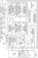
- FIG. 2 an illustration of a set of entities and a set of entity sensory representations is depicted in the form of a block diagram in accordance with an illustrative embodiment.
- Set of entities 200 and set of entity sensory representations 202 are depicted.
- Set of entities 200 includes aircraft 204, corporate management team 206, manufacturing instructions 208, and alert system 210.
- Each of aircraft 204, corporate management team 206, manufacturing instructions 208, and alert system 210 is an example of one implementation for entity 108 in Figure 1 .
- Aircraft 204 is comprised of plurality of aircraft sections 212.
- Corporate management team 206 is comprised of plurality of employees 214.
- Manufacturing instructions 208 is comprised of plurality of steps 216.
- Alert system 210 is comprised of plurality of alerts 218.
- Each of plurality of aircraft sections 212, plurality of employees 214, plurality of steps 216, and plurality of alerts 218 is an example of one implementation for plurality of items 110 in Figure 1 .
- set of entity sensory representations 202 includes aircraft image 220, picture cloud 222, audio recording 224, and audio recording group 226.
- Each of aircraft image 220, picture cloud 222, audio recording 224, and audio recording group 226 may be an example of one implementation for entity sensory representation 102 in Figure 1 .
- Aircraft image 220, picture cloud 222, audio recording 224, and audio recording group 226 are sensory representations of aircraft 204, corporate management team 206, manufacturing instructions 208, and alert system 210, respectively.
- aircraft image 220 may be comprised of plurality of image portions 228.
- Picture cloud 222 may be comprised of plurality of employee pictures 230.
- audio recording 224 may be comprised of plurality of audio sections 232.
- Audio recording group 226 may be comprised of plurality of audio recordings 234.
- Each of plurality of image portions 228, plurality of employee pictures 230, plurality of audio sections 232, and plurality of audio recordings 234 may be an example of one implementation for plurality of sensory representations 112 in Figure 1 . Further, plurality of image portions 228, plurality of employee pictures 230, plurality of audio sections 232, and plurality of audio recordings 234 represent plurality of aircraft sections 212, plurality of employees 214, plurality of steps 216, and plurality of alerts 218, respectively.
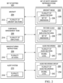
- the set of parameters that are scalable for each of plurality of image portions 228 may be set of dimensions 236.
- set of dimensions 236 includes a width and a height of an image portion.
- the set of parameters that are scalable for each of plurality of employee pictures 230 may be set of dimensions 238.
- each of plurality of audio sections 232 may have a single scalable parameter, which is decibel level 240.
- each of plurality of audio recordings 234 may have a single scalable parameter, which is decibel level 242.
- set of entity sensory representations 202 may include other types of sensory representations in other illustrative examples.
- other entity sensory representations may be tactile, olfactory, or gustatory.
- an entity sensory representation may correspond to more than one human sense.
- transformer 100 in Figure 1 and set of entities 200 and set of entity sensory representations 202 in Figure 2 are not meant to imply physical or architectural limitations to the manner in which an illustrative embodiment may be implemented.
- Other components in addition to or in place of the ones illustrated may be used. Some components may be optional.
- the blocks are presented to illustrate some functional components. One or more of these blocks may be combined, divided, or combined and divided into different blocks when implemented in an illustrative embodiment.
- transformer 100 may normalize the set of parameters for each of plurality of sensory representations 112 prior to adjusting these parameters.
- set of parameters 136 may be normalized to form normalized set of parameters 154. Normalized set of parameters 154 may then be adjusted using set of scale factors 138 to form scaled set of parameters 141.
- set of entities 200 may include other types of entities.
- set of entities 200 may include a spacecraft, a building, a corporate infrastructure, a financial portfolio, a safety manual, or some other type of entity.
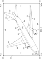
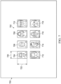
- FIG. 3 an illustration of a display of an aircraft image that visually represents an aircraft is depicted in accordance with an illustrative embodiment.
- display 300 of aircraft image 301 may be visually presented by a display device such as, for example, without limitation, display device 152 in Figure 1 .
- aircraft image 301 is an example of one implementation for transformed entity image 148.
- Aircraft image 301 in display 300 is a visual representation of an aircraft.
- the aircraft is an example of an entity, such as entity 108 in Figure 1 .
- aircraft image 301 may be comprised of plurality of image portions 303.
- Plurality of image portions 303 includes fuselage portion 302, cockpit portion 304, tail portion 306, rudder portion 307, right wing portion 308, left wing portion 310, right aileron portion 312, left aileron portion 314, right engine portion 316, and left engine portion 318.
- Plurality of image portions 303 represents the different aircraft sections or aircraft regions of an aircraft that are of interest.
- a total display area for display 300 may be defined by identifying top boundary 320, left boundary 322, bottom boundary 324, and right boundary 326 of display 300. Identifying the boundaries of display 300 allows the coordinates for the four corners formed by these boundaries to be identified. In particular, the x,y-coordinates for each corner may be identified. In particular, the coordinates for first corner 328, second corner 330, third corner 332, and fourth corner 334 may be identified. With these corner coordinates, the x,y-coordinates for center point 336 may also be identified. Center point 336 is the x,y center of display 300.
- the total display area for display 300 may also be three-dimensional and may have three-dimensional boundaries.
- center point 336 may comprise three-dimensional coordinates, such as x,y,z-coordinates.
- the total output area for the output device may be n-dimensional and have n-dimensional boundaries. Consequently, a center point of this total output area may comprise n-dimensional coordinates.
- All of this information may be used to define a plurality of display areas within display 300 corresponding to plurality of image portions 303 of aircraft image 301. These display areas are outlined in Figure 4 below.
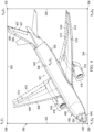
- FIG. 4 an illustration of display areas for the image portions of aircraft image 301 from Figure 3 is depicted in accordance with an illustrative embodiment.
- plurality of display areas 400 has been defined within display 300.
- plurality of display areas 400 includes fuselage display area 402, cockpit display area 404, tail display area 406, rudder display area 407, right wing display area 408, left wing display area 410, right aileron display area 412, left aileron display area 414, right engine display area 416, and left engine display area 418.
- Fuselage display area 402 cockpit display area 404, tail display area 406, rudder display area 407, right wing display area 408, left wing display area 410, right aileron display area 412, left aileron display area 414, right engine display area 416, and left engine display area 418 contain fuselage portion 302, cockpit portion 304, tail portion 306, rudder portion 307, right wing portion 308, left wing portion 310, right aileron portion 312, left aileron portion 314, right engine portion 316, and left engine portion 318, respectively.
- coordinates may be identified for each of the display areas identified. For example, without limitation, a leftmost x-coordinate, a rightmost x-coordinate, a topmost y-coordinate, and a bottommost y-coordinate may be identified for each of the display areas. These coordinates may be used to establish a width and a height for each of the display areas.
- a reference center point for each of the display areas may then be identified using the coordinates, the width and height, or both.
- cockpit center point 420 may be identified for cockpit display area 404. Thereafter, a distance from the reference center point identified for each of the display areas to center point 336 is identified.
- Table 500 has column 502, column 503, and column 504.
- Column 502 identifies the different aircraft sections of the aircraft represented by aircraft image 301 in Figures 3-4 .
- Column 503 identifies the energy usage for each of the aircraft sections. In this illustrative example, energy usage is an example of a measurable factor of interest, such as measurable factor of interest 126 in Figure 1 .
- Column 504 identifies the scale factor that may be calculated for the image portions corresponding to the aircraft sections identified in column 502.
- Row 506 indicates that the fuselage of the aircraft has an energy usage with a value of low. Row 506 further indicates that the corresponding scale factor to be used for fuselage portion 302 of aircraft image 301 in Figures 3-4 is 1.
- Row 508 indicates that the cockpit of the aircraft has an energy usage with a value of high. Row 508 further indicates that the corresponding scale factor to be used for cockpit portion 304 of aircraft image 301 in Figures 3-4 is 2.
- Row 510 indicates that the right engine of the aircraft has an energy usage with a value of very high. Row 510 further indicates that the corresponding scale factor to be used for right engine portion 316 of aircraft image 301 in Figures 3-4 is 3.
- the scale factors identified in column 504 may be used to modify the corresponding image portions of aircraft image 301 in Figures 3-4 .
- these scale factors may be used to resize the display areas of display 300 corresponding to these image portions to resize the image portions.
- FIG. 6 an illustration of a display of a transformed aircraft image is depicted in accordance with an illustrative embodiment.
- aircraft image 301 in Figures 3-4 has been transformed into transformed aircraft image 600 within display 300.
- scale factors identified in column 504 of table 500 in Figure 5 have been used to modify the image portions of aircraft image 301 in Figures 3-4 to form transformed aircraft image 600.
- Transformed aircraft image 600 includes plurality of modified image portions 601 that have been modified based on the scale factors identified in column 504 in table 500 in Figure 5 .
- each of plurality of image portions 303 from Figure 3 has been increased in size by the corresponding scale factor in Figure 5 .
- the new modified image portion may be centered about a new center point within display 300.
- the distance from the previously calculated reference center point for the original display area to display center point 336 may be scaled by the corresponding scale factor.
- the new modified image portion may be centered at a new center point having the scaled distance away from center point 336.
- the type of transformed entity image that results by performing this process for each of the modified image portions may be referred to as an exploded, transformed entity image.
- transformed aircraft image 600 may then be adjusted in the entirety such that transformed aircraft image 600 may be displayed within the original total display area of display 300.
- transformed aircraft image 600 may be scaled to fit within the original total display area of display 300.
- modified image portions 601 include modified fuselage portion 602, modified cockpit portion 604, modified tail portion 606, modified rudder portion 607, modified right wing portion 608, modified left wing portion 610, modified right aileron portion 612, modified left aileron portion 614, modified right engine portion 616, and modified left engine portion 618.
- modified cockpit portion 604 is larger than cockpit portion 304 in Figure 3 .
- modified right engine portion 616 and modified left engine portion 618 are larger than right engine portion 316 and left engine portion 318, respectively, in Figure 3 .
- Modified cockpit portion 604, modified right engine portion 616, and modified left engine portion 618 are larger, proportionally, than the other modified portions of transformed aircraft image 600.
- the proportionally increased size of modified cockpit portion 604, modified right engine portion 616, and modified left engine portion 618 provides an understanding, at a glance, that the cockpit, right engine, and left engine, respectively, have increased energy usage as compared to the other aircraft sections of the aircraft. In this manner, the relative significance of the aircraft sections represented by plurality of modified image portions 601 with respect to energy usage may be quickly and easily understood using transformed aircraft image 600.
- picture cloud 700 is an example of one implementation for entity sensory representation 102 in Figure 1 .
- picture cloud 700 may be an example of one implementation for entity image 142 in Figure 1 .
- Picture cloud 700 visually represents a social networking group.
- This social networking group may be a singular group in which the members of the social networking group are grouped based on one or more factors.
- the social networking group may be comprised of members that have signed up on a dating website, a group of buyers, a group of sellers, or some other type of group.
- picture cloud 700 includes plurality of member pictures 702, which may be an example of one implementation for plurality of image portions 144 in Figure 1 .
- Plurality of member pictures 702 includes member pictures 704, 706, 708, 710, 712, 714, 716, and 718.
- Plurality of member pictures 702 represents the plurality of members in the social networking group.
- the measurable factor of interest for each of the plurality of members may be a level of social networking activity for each member.
- the value for this level of social networking activity may be the number of posts created by each member.
- each of plurality of member pictures 702 may be considered at "baseline.”
- each of plurality of member pictures 702 has a same width 720 and height 722.
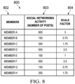
- table 800 has column 802, column 803, and column 804.
- Column 802 identifies the different members of the social network group represented by plurality of member pictures 702 in Figure 7 .
- Column 803 identifies the social networking activity of each of the members based on the number of posts created by each member.
- Column 804 identifies the scale factor calculated for each of plurality of member pictures 702 based on the values for social networking activity of the members represented by plurality of member pictures 702 identified in column 803.
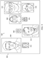
- Transformed picture cloud 900 may be an example of one implementation for transformed entity image 148 in Figure 1 .
- Transformed picture cloud 900 includes plurality of modified member pictures 902.
- each of plurality of member pictures 702 from Figure 7 has been resized using the corresponding scale factor identified in column 804 to form plurality of modified member pictures 902.
- Plurality of modified member pictures 902 includes modified member pictures 904, 906, 908, 910, 912, 914, 916, and 918, which are the modified versions of member pictures 704, 706, 708, 710, 712, 714, 716, and 718, respectively, in Figure 7 .
- the relative position of each of plurality of modified member pictures 902 within transformed picture cloud 900 may be determined based on scale factors used to perform the transformation. For example, plurality of modified member pictures 902 may be arranged from largest scale factor to smallest scale factor in a left to right direction, in a clockwise manner, or in some other manner.
- audio recording group 1000 is an example of one implementation for entity sensory representation 102 in Figure 1 .
- Audio recording group 1000 may represent an alert system.
- audio recording group 1000 includes plurality of audio recordings 1001 that represent a plurality of alerts that form the alert system.
- Plurality of audio recordings 1001 may be an example of one implementation for plurality of sensory representations 112 in Figure 1 .
- Each of the plurality of alerts may be an alert that indicates a threat to a particular room in a building as identified by a security system.
- the measurable factor of interest for these alerts may be the threat level.
- the value for the threat level may be selected from one of very minor, minor, moderate, serious, and very serious.
- Plurality of audio recordings 1001 includes audio recordings 1002, 1004, 1006, 1008, 1010, 1012, 1014, 1016, and 1018.
- each of plurality of audio recordings 1001 is at a baseline at which each audio recording is configured to play with a same loudness or decibel level. This baseline may be set to, for example, a moderate threat level.
- table 1100 includes column 1102, column 1103, and column 1104.
- Column 1102 identifies the different alerts represented by plurality of audio recordings 1001 in Figure 10 .
- Column 1103 identifies a current threat level for each of these alerts.
- Column 1104 identifies the scale factor calculated for use in modifying each of plurality of audio recordings 1001 in Figure 10 based on the threat level of the corresponding alert.
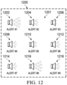
- FIG. 12 an illustration of a transformed audio recording group is depicted in accordance with an illustrative embodiment.
- audio recording group 1000 from Figure 10 has been transformed into transformed audio recording group 1200.
- Transformed audio recording group 1200 is another example of one implementation for transformed entity sensory representation 104 in Figure 1 .
- Transformed audio recording group 1200 includes plurality of modified audio recordings 1201, which may be another example of one implementation for plurality of modified sensory representations 132 in Figure 1 .
- Each of plurality of audio recordings 1001 in Figure 10 has been modified using the corresponding scale factor identified in Figure 11 to form plurality of modified audio recordings 1201.
- plurality of modified audio recordings 1201 includes modified audio recordings 1202, 1204, 1206, 1208, 1210, 1212, 1214, 1216, and 1218.
- Modified audio recordings 1202, 1204, 1206, 1208, 1210, 1212, 1214, 1216, and 1218 may be the modified versions of audio recordings 1002, 1004, 1006, 1008, 1010, 1012, 1014, 1016, and 1018, respectively.
- Plurality of modified audio recordings 1201 may be played in succession, one after the other.
- a user, listening to plurality of modified audio recordings 1201 may be able to quickly and easily understand the relative significance with respect to the threat level of each of the alerts represented by plurality of modified audio recordings 1201. For example, alerts corresponding to higher threat levels may be played at higher volumes as compared to alerts corresponding to lower threat levels.
- a user may, for example, be able to quickly and easily determine which of the alerts, and thereby rooms in the building, may need to be addressed first.
- a particular modified audio recording in plurality of modified audio recordings 1201 may be played throughout an entire building or other area when the corresponding alert is appropriate.
- the volume at which the modified audio recording is played may provide an understanding of the threat level associated with that alert.
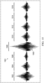
- audio recording 1300 may be an example of one implementation for entity sensory representation 102 in Figure 1 .
- Audio recording 1300 represents manufacturing instructions.
- audio recording 1300 is a recording of a human operator providing verbal instructions for performing a manufacturing operation.
- audio recording 1300 includes plurality of sections 1301.
- Plurality of sections 1301 may be an example of one implementation for plurality of sensory representations 112 in Figure 1 .
- Each of plurality of sections 1301 represents the instructions for performing a different step of the manufacturing operation.
- plurality of sections 1301 includes sections 1302, 1304, 1306, 1308, 1310, 1312, 1314, and 1316.
- Each of plurality of sections 1301 is at baseline in this example.
- each of plurality of sections 1301 is configured to play at a same loudness or similar decibel level.
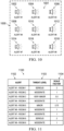
- table 1400 includes column 1402, column 1403, and column 1404.
- Column 1402 identifies the different steps for which instructions are provided by audio recording 1300 in Figure 13 .
- Column 1403 identifies the importance assigned to the different steps.
- Column 1404 identifies the scale factors calculated for plurality of sections 1301 representing the instructions for the different steps. These scale factors are used to modify a loudness of each of plurality of sections 1301.
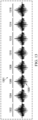
- FIG. 15 an illustration of a transformed audio recording is depicted in accordance with an illustrative embodiment.
- audio recording 1300 from Figure 13 has been transformed into transformed audio recording 1500.
- Transformed audio recording 1500 is yet another example of one implementation for transformed entity sensory representation 104 in Figure 1 .
- Transformed audio recording 1500 includes plurality of modified sections 1501.
- Plurality of modified sections 1501 includes modified sections 1502, 1504, 1506, 1508, 1510, 1512, 1514, and 1516.
- the loudness of each of plurality of sections 1301 has been adjusted based on the corresponding scale factor identified in Figure 14 for the corresponding step represented by each section to form plurality of modified sections 1501.
- plurality of modified sections 1501 provides the user with a sensory understanding of the relative importance of the plurality of steps represented by plurality of modified sections 1501.
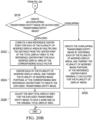
- FIG. 16 an illustration of a process for modifying an entity sensory representation that represents an entity is depicted in the form of a flowchart in accordance with an illustrative embodiment.
- the process illustrated in Figure 16 may be implemented using transformer 100 in Figure 1 to transform an entity sensory representation, such as entity sensory representation 102 in Figure 1 .
- the process may begin by receiving an entity sensory representation that represents an entity (operation 1600 ).
- the entity sensory representation comprises a plurality of sensory representations that represent a plurality of items that are part of the entity.
- Each of the plurality of items may be associated with a set of values for a set of measurable factors of interest.
- a set of scale factors is calculated for each of the plurality of sensory representations based on the set of values associated with each of the plurality of items (operation 1602 ).
- the plurality of sensory representations may then be modified using the set of scale factors calculated for each of the plurality of sensory representations to form a plurality of modified sensory representations that establish a relative relationship between the plurality of items represented by the plurality of modified sensory representations with respect to the set of measurable factors of interest (operation 1604 ), with the process terminating thereafter.
- FIG. 17 an illustration of a process for creating an entity sensory representation is depicted in the form of a flowchart in accordance with an illustrative embodiment.
- the process illustrated in Figure 17 may be implemented to form an entity sensory representation, such as entity sensory representation 102 in Figure 1 .
- the process begins by identifying an entity comprising a plurality of items (operation 1700 ).
- the entity may be identified in operation 1700 by a computer system, such as computer system 106 in Figure 1 , receiving input comprising one or more n -dimensional arrays of items.
- the one or more n -dimensional arrays of items may be stored in the computer system using one or more data structures.
- a sensory representation is obtained for each of the plurality of items (operation 1702 ).
- the sensory representations may be obtained by receiving the sensory representations as input at the computer system, retrieving the sensory representations from a database or cloud storage, creating new sensory representations, or in some other manner.
- the sensory representations obtained in operation 1702 may take the form of images.
- the images may be received as input from an imaging system; retrieved from a database, server system, or cloud storage; created based on predetermined criteria or specifications; created by a user using a graphics program; or obtained in some other manner.
- a set of parameters is quantified for each of the sensory representations (operation 1704 ).
- a value for each of the set of parameters may be acquired, measured, or quantified in some other manner for each of the plurality of sensory representations.
- the set of parameters may include a width and height in pixels.
- the quantified set of parameters may be normalized to form a normalized set of parameters for each of the sensory representations (operation 1706 ).
- the sensory representations are then modified using the normalized set of parameters to form a plurality of sensory representations that together form an entity sensory representation (operation 1708 ), with the process terminating thereafter.
- each of the plurality of sensory representations may be set to a same baseline.
- the width and height of the images may be normalized in operation 1706 such that each of the images may be modified in operation 1708 to have a baseline width and a baseline height in pixels.
- FIG. 18 an illustration of a process for calculating a set of scale factors for each of a plurality of sensory representations that form an entity sensory representation is depicted in the form of a flowchart in accordance with an illustrative embodiment.
- the process illustrated in Figure 18 may be implemented to identify a set of scale factors for, for example, each of plurality of sensory representations 112 in Figure 1 .
- the process begins by identifying a factor of interest for a plurality of items that form an entity (operation 1800 ). In other illustrative examples, more than one factor of interest may be identified in operation 1800.
- the factor of interest identified in operation 1800 may be measurable. Further, the factor of interest may be static or dynamic. When the factor of interest is static, a value measured for the factor of interest may not change over time. When the factor of interest is dynamic, a value measured for the factor of interest may change over time.
- the factor of interest may be multi-dimensional. For example, the factor of interest may be a position that comprises three coordinates.
- a value for the factor of interest may be identified for each of the plurality of items (operation 1802 ).
- the value may be quantified by at least one of performing a measurement, interpreting sensor data, converting subjective information into a value, or performing some other type of quantification.
- the phrase "at least one of,” when used with a list of items, means different combinations of one or more of the listed items may be used and only one of each item in the list may be needed. In other words, “at least one of” means any combination of items and number of items may be used from the list but not all of the items in the list are required.
- the item may be a particular object, thing, or a category.
- “at least one of item A, item B, or item C” or “at least one of item A, item B, and item C” may include, without limitation, item A, item A and item B, or item B. This example also may include item A, item B, and item C or item B and item C. Of course, any combinations of these items may be present. In other examples, "at least one of” may be, for example, without limitation, two of item A; one of item B; and ten of item C; four of item B and seven of item C; or other suitable combinations.
- an initial scale factor may be calculated for each of the plurality of items (operation 1804 ).
- the initial scale factor for a particular item may be calculated by dividing the value identified for the factor of interest for the particular item in operation 1802 by a sum of all of the values identified for the plurality of items.
- the initial scale factor may be computed in some other manner in other illustrative examples.
- the scale factor may be referred to as a computed relative significance.
- a final scale factor may be calculated for each of the plurality of sensory representations corresponding to the plurality of items using a nonlinear factor (operation 1806 ), with the process terminating thereafter.
- the nonlinear factor may be a logarithmic factor. Operation 1806 may be performed by multiplying the initial scale factor identified for a particular item by the logarithmic factor and setting the product of this multiplication as the final scale factor for the corresponding sensory representation.
- FIG. 19 an illustration of a process for creating a transformed entity sensory representation is depicted in the form of a flowchart in accordance with an illustrative embodiment.
- the process illustrated in Figure 19 may be implemented to transform the entity sensory representation formed by the process described in Figure 17 using the scale factors identified for the plurality of sensory representations in the entity sensory representation as described in Figure 18 .
- the process may begin by scaling the normalized set of parameters for each of the plurality of sensory representations to form a scaled set of parameters for each of the plurality of sensory representations (operation 1900 ).
- a plurality of modified sensory representations may be created using the scaled set of parameters formed for each of the plurality of sensory representations (operation 1902 ).
- a transformed entity sensory representation may be created using the plurality of modified sensory representations (operation 1904 ).
- Operation 1904 may be performed in any number of ways.
- the plurality of modified sensory representations may be combined, overlapped, sequenced, positioned relative to each other, or manipulated in any number of ways to form transformed entity sensory representation.
- the transformed entity sensory representation may then be output to establish, using at least one human sense, a relative relationship between the plurality of items represented by the plurality of modified sensory representations with respect to the factor of interest (operation 1906 ), with the process terminating thereafter.
- the factor of interest may be a set of measurable factors of interest.
- FIG. 20A and 20B an illustration of a process for creating a transformed entity image is depicted in the form of a flowchart in accordance with an illustrative embodiment.
- the process illustrated in Figures 20A and 20B may be implemented to create, for example, without limitation, transformed entity image 148 in Figure 1 .
- the process may begin by identifying a plurality of image portions of an entity image (operation 2000). Next, boundaries of a total display area for displaying the entity image are identified (operation 2002).
- Coordinates for the boundaries of the total display area are then identified (operation 2004). Depending on the shape of the total display area, these coordinates may be for the corners of the total display area, starting end points and ending end points for the boundaries of the total display area, or for other types of points along the boundaries of the total display area. Then, a center point of the total display area is identified (operation 2006).
- a plurality of display areas for the plurality of image portions is identified in the total display area (operation 2008).
- a set of size parameters are quantified for each of the plurality of display areas (operation 2010).
- the set of size parameters for each of the plurality of display areas may include, for example, a width in pixels and a height in pixels for each display area.
- a reference center point may be identified for each of the plurality of display areas (operation 2012).
- a distance from each reference center point identified to the center point of the total display area is computed (operation 2014).
- this distance may be calculated using Cartesian point-coordinates such as x,y-coordinates, or x,y,z-coordinates.
- the distance may be calculated using distance-angle vectors in two dimensions, three dimensions, n-dimensions, or some combination thereof using some other type of distance measurement technique.
- Each of the set of size parameters for each of the plurality of display areas is multiplied by a scale factor computed for the image portion corresponding to each display area to form a plurality of modified display areas and thereby, a plurality of modified image portions (operation 2016).
- the resizing may be a one-to-one resizing. For example, resizing a display area by a scale factor of 1 may not change a size of the display area. Thus, the size of the corresponding image portion may not be changed.
- one or more of the plurality of modified image portions may overlap over other modified image portions.
- the modified display areas, and thereby the modified image portions may be added to the total display area starting from the modified image portion associated with the smallest scale factor and ending with the modified image portion associated with the largest scale factor. In this manner, a modified image portion representing an item with greater relative significance may overlap another modified image portion representing an item with lesser relative significance.
- the process computes a new reference center point for each of the plurality of modified display areas by multiplying the distance from the center point of the total display area to the reference center point for each modified display area by the corresponding scale factor (operation 2022).
- each of the plurality of modified display areas, and thereby the plurality of modified image portions may be centered at the corresponding new reference center point to create the exploded transformed entity image (operation 2024) .
- operation 2024 or operation 2026 may include adding lines to reconnect the plurality of modified image portions.
- a continuous relationship may be present between the sensory representations that make up an entity sensory representation.
- a continuous relationship may be present between the plurality of image portions identified in operation 2000 when the entity image is an aircraft and the plurality of image portions are parts of the aircraft.
- a continuous relationship may be present between segments of speech in an audio recording. When this type of continuous relationship is present in an entity image, it may be desirable to preserve this continuity between the plurality of modified portions that form an exploded transformed entity image.
- one or more techniques or algorithms may be used to create intermediary sensory representation content to preserve continuity between the plurality of modified image portions in the exploded transformed entity image formed in operation 2024 after the plurality of modified image portions have been centered at the corresponding new reference center points in operation 2024.
- the one or more techniques or algorithms used may include, for example, without limitation, an interpolation technique, a smoothing algorithm, a filling algorithm, an extrapolation technique, a linear extrapolation technique, a drawing technique, some other type of algorithm or technique, or some combination thereof.
- an operation similar to operation 2026 may be performed after operation 2020.
- the new total display area for the overlapping transformed entity image may be adjusted to have a same size as the original total display area.
- operation 2026 may be performed to adjust the new total display area to some other size.
- FIG. 21 an illustration of a process for creating a transformed entity sensory representation is depicted in accordance with an illustrative embodiment.
- the process illustrated in Figure 21 may be used to create, for example, without limitation, transformed entity sensory representation 104 in Figure 1 .
- the process may begin by identifying a plurality of sensory representations that make up an entity sensory representation (operation 2100 ). Next, boundaries of a total output range for outputting the entity sensory representation are identified (operation 2102 ). Coordinates of the boundaries of the total output range are then identified (operation 2104 ). Then, a center point of the total output range is identified (operation 2106 ).
- the total output range may take different forms, depending on the type of entity sensory representation being processed.
- the boundaries of the total output range may correspond to one or more dimensions such as, for example, without limitation, time, frequency, sound pressure, and intensity.
- the boundaries of the total output range for an audio recording may take the form of parameters such as time and sound pressure.
- the coordinates for these boundaries may include, for example, a start time, and end time, and a maximum sound pressure level and minimum sound pressure level for the boundary corresponding to sound pressure.
- a center point for the total output range may be comprised of the middle time between the start and end times and the mid-point between the maximum and minimum sound pressure levels.
- the boundaries for the audio recordings may take the form of parameters, such as frequency and one of volume, intensity, or sound pressure.
- the coordinates for these boundaries may include, for example, a lowest frequency and highest frequency and a maximum volume level and minimum volume level.
- the center point for the total output range may then be comprised of the mid-frequency point and the middle volume level.
- the mid-frequency point may be computed using linear or logarithmic measurements of the frequencies.
- a plurality of outputs for the plurality of sensory representations is identified within the total output range (operation 2108).
- the plurality of outputs may be the corresponding sections of the total output range.
- a set of parameters are quantified for each of the plurality of outputs (operation 2110).
- the set of parameters for each of the plurality of outputs may include, for example, a frequency range, a volume range, a time interval, an intensity range, or some other type of parameter.
- a reference center point may be identified for each of the plurality of outputs (operation 2112).
- a distance from each reference center point identified to the center point of the total output range is computed (operation 2114).
- this distance may be a temporal distance in the case of audio.
- each of the set of parameters for each of the plurality of outputs is multiplied by a scale factor computed for the sensory representation corresponding to each output to form a plurality of modified outputs and thereby, a plurality of modified sensory representations (operation 2116).
- each output may be scaled in frequency, volume, time, intensity, sound pressure, or some other parameter.
- a new reference center point may be computed for each of the plurality of modified outputs by multiplying the distance from the center point of the total output range to the reference center point for each modified output by the corresponding scale factor (operation 2118).
- the plurality of modified outputs, and thereby the plurality of sensory representations may be reconfigured using the corresponding new reference center points identified to create the transformed entity sensory representation (operation 2120), with the process terminating thereafter.
- each block in the flowcharts or block diagrams may represent a module, a segment, a function, a portion of an operation or step, some combination thereof.
- the function or functions noted in the blocks may occur out of the order noted in the figures.
- two blocks shown in succession may be executed substantially concurrently, or the blocks may sometimes be performed in the reverse order, depending upon the functionality involved.
- other blocks may be added in addition to the illustrated blocks in a flowchart or block diagram.
- operation 1706 in Figure 17 may be an optional step.
- the normalized set of parameters formed in operation 1706 may be referred to as an optionally normalized set of parameters.
- the process described in Figure 17 above may be made to terminate after operation 1704 such that the sensory representations with the quantified sets of parameters are used to form the entity sensory representation.
- operation 1806 in Figure 18 may be an optional step. When operation 1806 is not performed, the initial scale factor computed in operation 1804 for each of plurality of items may be used as the final scale factor for each corresponding sensory representation.
- Data processing system 2200 may be used to implement computer system 106 in Figure 1 .
- data processing system 2200 includes communications framework 2202, which provides communications between processor unit 2204, storage devices 2206, communications unit 2208, input/output unit 2210, and display 2212.
- communications framework 2202 may be implemented as a bus system.
- Processor unit 2204 is configured to execute instructions for software to perform a number of operations.
- Processor unit 2204 may comprise at least one of a number of processors, a multi-processor core, or some other type of processor, depending on the implementation.
- processor unit 2204 may take the form of a hardware unit, such as a circuit system, an application specific integrated circuit (ASIC), a programmable logic device, or some other suitable type of hardware unit.
- ASIC application specific integrated circuit
- Storage devices 2206 may be in communication with processor unit 2204 through communications framework 2202.
- a storage device also referred to as a computer readable storage device, is any piece of hardware capable of storing information on a temporary basis, a permanent basis, or both. This information may include, but is not limited to, data, program code, other information, or some combination thereof.
- Memory 2214 and persistent storage 2216 are examples of storage devices 2206.
- Memory 2214 may take the form of, for example, a random access memory or some type of volatile or nonvolatile storage device.
- Persistent storage 2216 may comprise any number of components or devices.
- persistent storage 2216 may comprise a hard drive, a flash memory, a rewritable optical disk, a rewritable magnetic tape, or some combination of the above.
- the media used by persistent storage 2216 may or may not be removable.
- Communications unit 2208 allows data processing system 2200 to communicate with other data processing systems, devices, or both. Communications unit 2208 may provide communications using physical communications links, wireless communications links, or both.
- Input/output unit 2210 allows input to be received from and output to be sent to other devices connected to data processing system 2200.
- input/output unit 2210 may allow user input to be received through a keyboard, a mouse, some other type of input device, or a combination thereof.
- input/output unit 2210 may allow output to be sent to a printer connected to data processing system 2200.
- Display 2212 is configured to display information to a user.
- Display 2212 may comprise, for example, without limitation, a monitor, a touch screen, a laser display, a holographic display, a virtual display device, some other type of display device, or a combination thereof.
- Display 2212 may be an example of one manner in which display device 152 in Figure 1 may be implemented.
- processor unit 2204 may perform the processes of the different illustrative embodiments using computer-implemented instructions. These instructions may be referred to as program code, computer usable program code, or computer readable program code and may be read and executed by one or more processors in processor unit 2204.
- program code 2218 is located in a functional form on computer readable media 2220, which is selectively removable, and may be loaded onto or transferred to data processing system 2200 for execution by processor unit 2204.
- Program code 2218 and computer readable media 2220 together form computer program product 2222.
- computer readable media 2220 may be computer readable storage media 2224 or computer readable signal media 2226.
- Computer readable storage media 2224 is a physical or tangible storage device used to store program code 2218 rather than a medium that propagates or transmits program code 2218.
- Computer readable storage media 2224 may be, for example, without limitation, an optical or magnetic disk or a persistent storage device that is connected to data processing system 2200.
- program code 2218 may be transferred to data processing system 2200 using computer readable signal media 2226.
- Computer readable signal media 2226 may be, for example, a propagated data signal containing program code 2218. This data signal may be an electromagnetic signal, an optical signal, or some other type of signal that can be transmitted over physical communications links, wireless communications links, or both.
- data processing system 2200 in Figure 22 is not meant to provide architectural limitations to the manner in which the illustrative embodiments may be implemented.
- the different illustrative embodiments may be implemented in a data processing system that includes components in addition to or in place of those illustrated for data processing system 2200. Further, components shown in Figure 22 may be varied from the illustrative examples shown.
- the illustrative embodiments provide a method and apparatus for using a sensory representation to provide an understanding of the relative significance of items in an entity with respect to one or more measurable factors of interest.
- transformed entity sensory representation 104 described in Figure 1 may allow a user to more quickly and easily understand the relative significance of items, the relative importance of items, or some other relative measure of items without needing to interpret, understand, or process the underlying data.
Landscapes
- Engineering & Computer Science (AREA)
- Business, Economics & Management (AREA)
- Strategic Management (AREA)
- Development Economics (AREA)
- Finance (AREA)
- Accounting & Taxation (AREA)
- Physics & Mathematics (AREA)
- General Physics & Mathematics (AREA)
- Theoretical Computer Science (AREA)
- Entrepreneurship & Innovation (AREA)
- Economics (AREA)
- General Business, Economics & Management (AREA)
- Marketing (AREA)
- Game Theory and Decision Science (AREA)
- Data Mining & Analysis (AREA)
- Computer Networks & Wireless Communication (AREA)
- Signal Processing (AREA)
- Human Resources & Organizations (AREA)
- Operations Research (AREA)
- Quality & Reliability (AREA)
- Tourism & Hospitality (AREA)
- User Interface Of Digital Computer (AREA)
- Information Retrieval, Db Structures And Fs Structures Therefor (AREA)
Applications Claiming Priority (1)
| Application Number | Priority Date | Filing Date | Title |
|---|---|---|---|
| US14/334,939 US9648091B2 (en) | 2014-07-18 | 2014-07-18 | Transforming sensory representations |
Publications (3)
| Publication Number | Publication Date |
|---|---|
| EP2975579A2 EP2975579A2 (en) | 2016-01-20 |
| EP2975579A3 EP2975579A3 (en) | 2016-11-02 |
| EP2975579B1 true EP2975579B1 (en) | 2025-01-29 |
Family
ID=53719648
Family Applications (1)
| Application Number | Title | Priority Date | Filing Date |
|---|---|---|---|
| EP15176797.7A Active EP2975579B1 (en) | 2014-07-18 | 2015-07-15 | Transforming sensory representations |
Country Status (6)
| Country | Link |
|---|---|
| US (1) | US9648091B2 (enExample) |
| EP (1) | EP2975579B1 (enExample) |
| JP (1) | JP6594071B2 (enExample) |
| CN (1) | CN105279559A (enExample) |
| AU (1) | AU2015202808B2 (enExample) |
| CA (2) | CA2893032C (enExample) |
Families Citing this family (3)
| Publication number | Priority date | Publication date | Assignee | Title |
|---|---|---|---|---|
| US10679306B2 (en) * | 2017-11-21 | 2020-06-09 | International Business Machines Corporation | Focus-object-determined communities for augmented reality users |
| US11216312B2 (en) * | 2018-08-03 | 2022-01-04 | Virtustream Ip Holding Company Llc | Management of unit-based virtual accelerator resources |
| KR102755385B1 (ko) * | 2019-10-24 | 2025-01-17 | 한국전자통신연구원 | 감각대체장치 및 방법 |
Citations (2)
| Publication number | Priority date | Publication date | Assignee | Title |
|---|---|---|---|---|
| US6639614B1 (en) * | 2000-07-10 | 2003-10-28 | Stephen Michael Kosslyn | Multi-variate data presentation method using ecologically valid stimuli |
| EP2518712A2 (en) * | 2011-04-29 | 2012-10-31 | Samsung Electronics Co., Ltd. | Method for displaying marker in a map service |
Family Cites Families (16)
| Publication number | Priority date | Publication date | Assignee | Title |
|---|---|---|---|---|
| JPH1083271A (ja) * | 1996-09-09 | 1998-03-31 | Toshiba Corp | ウィンドウシステム及び計算機システム並びにウインドウ表示方法 |
| JP2002077313A (ja) * | 2000-09-05 | 2002-03-15 | Fujitsu Denso Ltd | 警報表示システム及び警報表示方法 |
| WO2003042766A1 (en) * | 2001-11-13 | 2003-05-22 | Thinking Machines, Llc | Method and system for orthogonalizing input signals |
| US7841987B2 (en) * | 2004-03-30 | 2010-11-30 | Apneos Corporation | System and method for visualizing sleep-related information |
| JP2004272347A (ja) * | 2003-03-05 | 2004-09-30 | Hitachi Plant Eng & Constr Co Ltd | 工程計画支援システム |
| US20050254727A1 (en) * | 2004-05-14 | 2005-11-17 | Eastman Kodak Company | Method, apparatus and computer program product for determining image quality |
| JP4660264B2 (ja) * | 2005-04-22 | 2011-03-30 | 株式会社東芝 | 情報処理装置およびプログラム |
| WO2008139551A1 (ja) * | 2007-05-01 | 2008-11-20 | Osaka Electro-Communication University | 情報提示装置及び情報提示方法 |
| US8200037B2 (en) * | 2008-01-28 | 2012-06-12 | Microsoft Corporation | Importance guided image transformation |
| US9003280B2 (en) * | 2008-05-09 | 2015-04-07 | Vizio, Inc. | Displaying still and moving images of a constant size or images that occupy a specified percentage of a screen across different size display screens |
| KR20100008775A (ko) * | 2008-07-16 | 2010-01-26 | 한국전자통신연구원 | 실감 효과 표현 방법 및 그 장치 및 사용자 환경 정보 메타데이터가 기록된 컴퓨터로 읽을 수 있는 기록 매체 |
| CN101923427A (zh) * | 2009-06-16 | 2010-12-22 | 英业达股份有限公司 | 用户界面及其操作方法 |
| WO2013095724A1 (en) * | 2011-12-21 | 2013-06-27 | The Boeing Company | Panoptic visualization document layout |
| JP2013206271A (ja) * | 2012-03-29 | 2013-10-07 | Sony Corp | 情報処理装置、情報処理方法およびコンピュータプログラム |
| CN102970215A (zh) * | 2012-11-30 | 2013-03-13 | 上海市共进通信技术有限公司 | 实现火灾报警功能的家庭网关设备及报警功能控制方法 |
| US10003379B2 (en) * | 2014-05-06 | 2018-06-19 | Starkey Laboratories, Inc. | Wireless communication with probing bandwidth |
-
2014
- 2014-07-18 US US14/334,939 patent/US9648091B2/en active Active
-
2015
- 2015-05-25 AU AU2015202808A patent/AU2015202808B2/en active Active
- 2015-05-27 CA CA2893032A patent/CA2893032C/en active Active
- 2015-05-27 CA CA2904975A patent/CA2904975A1/en active Pending
- 2015-07-14 JP JP2015140204A patent/JP6594071B2/ja active Active
- 2015-07-15 EP EP15176797.7A patent/EP2975579B1/en active Active
- 2015-07-17 CN CN201510421046.5A patent/CN105279559A/zh active Pending
Patent Citations (2)
| Publication number | Priority date | Publication date | Assignee | Title |
|---|---|---|---|---|
| US6639614B1 (en) * | 2000-07-10 | 2003-10-28 | Stephen Michael Kosslyn | Multi-variate data presentation method using ecologically valid stimuli |
| EP2518712A2 (en) * | 2011-04-29 | 2012-10-31 | Samsung Electronics Co., Ltd. | Method for displaying marker in a map service |
Non-Patent Citations (1)
| Title |
|---|
| POPPINGA BENJAMIN ET AL: "TouchOver map : audio-tactile exploration of interactive maps", MOBILEHCI 2011, 1 January 2011 (2011-01-01), US, pages 545, XP055871284, ISBN: 978-1-4503-0541-9, DOI: 10.1145/2037373.2037458 * |
Also Published As
| Publication number | Publication date |
|---|---|
| US20160019674A1 (en) | 2016-01-21 |
| AU2015202808B2 (en) | 2020-04-16 |
| JP6594071B2 (ja) | 2019-10-23 |
| US9648091B2 (en) | 2017-05-09 |
| CA2904975A1 (en) | 2016-01-18 |
| CA2893032C (en) | 2018-10-02 |
| AU2015202808A1 (en) | 2016-02-04 |
| EP2975579A2 (en) | 2016-01-20 |
| CN105279559A (zh) | 2016-01-27 |
| JP2016024824A (ja) | 2016-02-08 |
| EP2975579A3 (en) | 2016-11-02 |
| CA2893032A1 (en) | 2016-01-18 |
Similar Documents
| Publication | Publication Date | Title |
|---|---|---|
| JP6650423B2 (ja) | シミュレート装置及びコンピュータ読取可能記憶媒体 | |
| Rockcastle et al. | Contrast measures for predicting perceptual effects of daylight in architectural renderings | |
| US7724250B2 (en) | Apparatus, method, and program for processing information | |
| Jansen et al. | A psychophysical investigation of size as a physical variable | |
| US10699453B2 (en) | Digital media environment for style-aware patching in a digital image | |
| US9007373B2 (en) | Systems and methods for creating texture exemplars | |
| Takahashi et al. | A system for three-dimensional gaze fixation analysis using eye tracking glasses | |
| US10445920B2 (en) | Methods, apparatus and system for analytics replay utilizing random sampling | |
| EP2975579B1 (en) | Transforming sensory representations | |
| US10089760B2 (en) | Techniques for dynamically displaying pie charts for direct comparison | |
| CN108182097B (zh) | 一种音量条的实现方法及装置 | |
| Bowman | Graphics for uncertainty | |
| Philpotts | Dimension: Fractal Forms and Periodical Texture | |
| JP6687940B2 (ja) | 素材評価方法、及び素材評価装置 | |
| US20240193747A1 (en) | System and Method for Point Cloud Generation | |
| Engel et al. | Neighborhood relation diagrams for local comparison of carbon footprints in urban planning | |
| Thelin et al. | Difference modeling for design space exploration and comparison of three-dimensional structural simulation results | |
| US11270359B2 (en) | Program, information processing apparatus, and information processing method | |
| Munoz et al. | Convolution‐based simulation of homogeneous subsurface scattering | |
| Dubois et al. | Evaluating the Visual Design of Graphical User Interfaces on Mobile Devices: A Family of Experiments | |
| JP6516690B2 (ja) | 解析装置および解析プログラム | |
| JPWO2022259801A5 (enExample) | ||
| CN113988902A (zh) | 点击率预测方法、装置、电子设备及可读存储介质 | |
| CN118379413A (zh) | 体检信息展示方法、装置、计算机设备、可读存储介质和程序产品 | |
| WO2022176204A1 (ja) | 触質情報提供システム、触質情報提供方法および触質情報提供用プログラム |
Legal Events
| Date | Code | Title | Description |
|---|---|---|---|
| PUAI | Public reference made under article 153(3) epc to a published international application that has entered the european phase |
Free format text: ORIGINAL CODE: 0009012 |
|
| 17P | Request for examination filed |
Effective date: 20150715 |
|
| AK | Designated contracting states |
Kind code of ref document: A2 Designated state(s): AL AT BE BG CH CY CZ DE DK EE ES FI FR GB GR HR HU IE IS IT LI LT LU LV MC MK MT NL NO PL PT RO RS SE SI SK SM TR |
|
| AX | Request for extension of the european patent |
Extension state: BA ME |
|
| PUAL | Search report despatched |
Free format text: ORIGINAL CODE: 0009013 |
|
| AK | Designated contracting states |
Kind code of ref document: A3 Designated state(s): AL AT BE BG CH CY CZ DE DK EE ES FI FR GB GR HR HU IE IS IT LI LT LU LV MC MK MT NL NO PL PT RO RS SE SI SK SM TR |
|
| AX | Request for extension of the european patent |
Extension state: BA ME |
|
| RIC1 | Information provided on ipc code assigned before grant |
Ipc: G06T 11/20 20060101AFI20160926BHEP |
|
| STAA | Information on the status of an ep patent application or granted ep patent |
Free format text: STATUS: EXAMINATION IS IN PROGRESS |
|
| 17Q | First examination report despatched |
Effective date: 20200511 |
|
| RAP3 | Party data changed (applicant data changed or rights of an application transferred) |
Owner name: THE BOEING COMPANY |
|
| GRAP | Despatch of communication of intention to grant a patent |
Free format text: ORIGINAL CODE: EPIDOSNIGR1 |
|
| STAA | Information on the status of an ep patent application or granted ep patent |
Free format text: STATUS: GRANT OF PATENT IS INTENDED |
|
| INTG | Intention to grant announced |
Effective date: 20241009 |
|
| GRAS | Grant fee paid |
Free format text: ORIGINAL CODE: EPIDOSNIGR3 |
|
| GRAA | (expected) grant |
Free format text: ORIGINAL CODE: 0009210 |
|
| STAA | Information on the status of an ep patent application or granted ep patent |
Free format text: STATUS: THE PATENT HAS BEEN GRANTED |
|
| P01 | Opt-out of the competence of the unified patent court (upc) registered |
Free format text: CASE NUMBER: APP_65005/2024 Effective date: 20241209 |
|
| AK | Designated contracting states |
Kind code of ref document: B1 Designated state(s): AL AT BE BG CH CY CZ DE DK EE ES FI FR GB GR HR HU IE IS IT LI LT LU LV MC MK MT NL NO PL PT RO RS SE SI SK SM TR |
|
| REG | Reference to a national code |
Ref country code: GB Ref legal event code: FG4D |
|
| REG | Reference to a national code |
Ref country code: CH Ref legal event code: EP |
|
| REG | Reference to a national code |
Ref country code: DE Ref legal event code: R096 Ref document number: 602015090928 Country of ref document: DE |
|
| REG | Reference to a national code |
Ref country code: IE Ref legal event code: FG4D |
|
| REG | Reference to a national code |
Ref country code: NL Ref legal event code: MP Effective date: 20250129 |
|
| PG25 | Lapsed in a contracting state [announced via postgrant information from national office to epo] |
Ref country code: NL Free format text: LAPSE BECAUSE OF FAILURE TO SUBMIT A TRANSLATION OF THE DESCRIPTION OR TO PAY THE FEE WITHIN THE PRESCRIBED TIME-LIMIT Effective date: 20250129 |
|
| PG25 | Lapsed in a contracting state [announced via postgrant information from national office to epo] |
Ref country code: RS Free format text: LAPSE BECAUSE OF FAILURE TO SUBMIT A TRANSLATION OF THE DESCRIPTION OR TO PAY THE FEE WITHIN THE PRESCRIBED TIME-LIMIT Effective date: 20250429 |
|
| PG25 | Lapsed in a contracting state [announced via postgrant information from national office to epo] |
Ref country code: FI Free format text: LAPSE BECAUSE OF FAILURE TO SUBMIT A TRANSLATION OF THE DESCRIPTION OR TO PAY THE FEE WITHIN THE PRESCRIBED TIME-LIMIT Effective date: 20250129 |
|
| PG25 | Lapsed in a contracting state [announced via postgrant information from national office to epo] |
Ref country code: PL Free format text: LAPSE BECAUSE OF FAILURE TO SUBMIT A TRANSLATION OF THE DESCRIPTION OR TO PAY THE FEE WITHIN THE PRESCRIBED TIME-LIMIT Effective date: 20250129 |
|
| PG25 | Lapsed in a contracting state [announced via postgrant information from national office to epo] |
Ref country code: ES Free format text: LAPSE BECAUSE OF FAILURE TO SUBMIT A TRANSLATION OF THE DESCRIPTION OR TO PAY THE FEE WITHIN THE PRESCRIBED TIME-LIMIT Effective date: 20250129 |
|
| REG | Reference to a national code |
Ref country code: LT Ref legal event code: MG9D |
|
| PG25 | Lapsed in a contracting state [announced via postgrant information from national office to epo] |
Ref country code: NO Free format text: LAPSE BECAUSE OF FAILURE TO SUBMIT A TRANSLATION OF THE DESCRIPTION OR TO PAY THE FEE WITHIN THE PRESCRIBED TIME-LIMIT Effective date: 20250429 Ref country code: IS Free format text: LAPSE BECAUSE OF FAILURE TO SUBMIT A TRANSLATION OF THE DESCRIPTION OR TO PAY THE FEE WITHIN THE PRESCRIBED TIME-LIMIT Effective date: 20250529 |
|
| REG | Reference to a national code |
Ref country code: AT Ref legal event code: MK05 Ref document number: 1764220 Country of ref document: AT Kind code of ref document: T Effective date: 20250129 |
|
| PG25 | Lapsed in a contracting state [announced via postgrant information from national office to epo] |
Ref country code: HR Free format text: LAPSE BECAUSE OF FAILURE TO SUBMIT A TRANSLATION OF THE DESCRIPTION OR TO PAY THE FEE WITHIN THE PRESCRIBED TIME-LIMIT Effective date: 20250129 |
|
| PG25 | Lapsed in a contracting state [announced via postgrant information from national office to epo] |
Ref country code: PT Free format text: LAPSE BECAUSE OF FAILURE TO SUBMIT A TRANSLATION OF THE DESCRIPTION OR TO PAY THE FEE WITHIN THE PRESCRIBED TIME-LIMIT Effective date: 20250529 Ref country code: LV Free format text: LAPSE BECAUSE OF FAILURE TO SUBMIT A TRANSLATION OF THE DESCRIPTION OR TO PAY THE FEE WITHIN THE PRESCRIBED TIME-LIMIT Effective date: 20250129 |
|
| PG25 | Lapsed in a contracting state [announced via postgrant information from national office to epo] |
Ref country code: GR Free format text: LAPSE BECAUSE OF FAILURE TO SUBMIT A TRANSLATION OF THE DESCRIPTION OR TO PAY THE FEE WITHIN THE PRESCRIBED TIME-LIMIT Effective date: 20250430 Ref country code: BG Free format text: LAPSE BECAUSE OF FAILURE TO SUBMIT A TRANSLATION OF THE DESCRIPTION OR TO PAY THE FEE WITHIN THE PRESCRIBED TIME-LIMIT Effective date: 20250129 |
|
| PG25 | Lapsed in a contracting state [announced via postgrant information from national office to epo] |
Ref country code: AT Free format text: LAPSE BECAUSE OF FAILURE TO SUBMIT A TRANSLATION OF THE DESCRIPTION OR TO PAY THE FEE WITHIN THE PRESCRIBED TIME-LIMIT Effective date: 20250129 |
|
| PG25 | Lapsed in a contracting state [announced via postgrant information from national office to epo] |
Ref country code: SE Free format text: LAPSE BECAUSE OF FAILURE TO SUBMIT A TRANSLATION OF THE DESCRIPTION OR TO PAY THE FEE WITHIN THE PRESCRIBED TIME-LIMIT Effective date: 20250129 |
|
| PG25 | Lapsed in a contracting state [announced via postgrant information from national office to epo] |
Ref country code: SM Free format text: LAPSE BECAUSE OF FAILURE TO SUBMIT A TRANSLATION OF THE DESCRIPTION OR TO PAY THE FEE WITHIN THE PRESCRIBED TIME-LIMIT Effective date: 20250129 |
|
| PG25 | Lapsed in a contracting state [announced via postgrant information from national office to epo] |
Ref country code: DK Free format text: LAPSE BECAUSE OF FAILURE TO SUBMIT A TRANSLATION OF THE DESCRIPTION OR TO PAY THE FEE WITHIN THE PRESCRIBED TIME-LIMIT Effective date: 20250129 |
|
| PGFP | Annual fee paid to national office [announced via postgrant information from national office to epo] |
Ref country code: DE Payment date: 20250729 Year of fee payment: 11 |
|
| PG25 | Lapsed in a contracting state [announced via postgrant information from national office to epo] |
Ref country code: IT Free format text: LAPSE BECAUSE OF FAILURE TO SUBMIT A TRANSLATION OF THE DESCRIPTION OR TO PAY THE FEE WITHIN THE PRESCRIBED TIME-LIMIT Effective date: 20250129 |
|
| PGFP | Annual fee paid to national office [announced via postgrant information from national office to epo] |
Ref country code: GB Payment date: 20250728 Year of fee payment: 11 |
|
| PGFP | Annual fee paid to national office [announced via postgrant information from national office to epo] |
Ref country code: FR Payment date: 20250725 Year of fee payment: 11 |
|
| PG25 | Lapsed in a contracting state [announced via postgrant information from national office to epo] |
Ref country code: EE Free format text: LAPSE BECAUSE OF FAILURE TO SUBMIT A TRANSLATION OF THE DESCRIPTION OR TO PAY THE FEE WITHIN THE PRESCRIBED TIME-LIMIT Effective date: 20250129 Ref country code: CZ Free format text: LAPSE BECAUSE OF FAILURE TO SUBMIT A TRANSLATION OF THE DESCRIPTION OR TO PAY THE FEE WITHIN THE PRESCRIBED TIME-LIMIT Effective date: 20250129 |
|
| PG25 | Lapsed in a contracting state [announced via postgrant information from national office to epo] |
Ref country code: RO Free format text: LAPSE BECAUSE OF FAILURE TO SUBMIT A TRANSLATION OF THE DESCRIPTION OR TO PAY THE FEE WITHIN THE PRESCRIBED TIME-LIMIT Effective date: 20250129 |
|
| PG25 | Lapsed in a contracting state [announced via postgrant information from national office to epo] |
Ref country code: SK Free format text: LAPSE BECAUSE OF FAILURE TO SUBMIT A TRANSLATION OF THE DESCRIPTION OR TO PAY THE FEE WITHIN THE PRESCRIBED TIME-LIMIT Effective date: 20250129 |
|
| REG | Reference to a national code |
Ref country code: DE Ref legal event code: R097 Ref document number: 602015090928 Country of ref document: DE |
|
| PLBE | No opposition filed within time limit |
Free format text: ORIGINAL CODE: 0009261 |
|
| STAA | Information on the status of an ep patent application or granted ep patent |
Free format text: STATUS: NO OPPOSITION FILED WITHIN TIME LIMIT |