EP2975440B1 - Illuminated microsurgical instrument including optical fiber with beveled end face - Google Patents
Illuminated microsurgical instrument including optical fiber with beveled end face Download PDFInfo
- Publication number
- EP2975440B1 EP2975440B1 EP15179907.9A EP15179907A EP2975440B1 EP 2975440 B1 EP2975440 B1 EP 2975440B1 EP 15179907 A EP15179907 A EP 15179907A EP 2975440 B1 EP2975440 B1 EP 2975440B1
- Authority
- EP
- European Patent Office
- Prior art keywords
- microsurgical instrument
- optical fiber
- face
- illuminated
- beveled end
- Prior art date
- Legal status (The legal status is an assumption and is not a legal conclusion. Google has not performed a legal analysis and makes no representation as to the accuracy of the status listed.)
- Active
Links
- 239000013307 optical fiber Substances 0.000 title claims description 70
- 230000003287 optical effect Effects 0.000 claims description 14
- 239000000523 sample Substances 0.000 claims description 11
- 238000001356 surgical procedure Methods 0.000 claims description 10
- 239000000463 material Substances 0.000 claims description 9
- 238000005253 cladding Methods 0.000 claims description 5
- 239000012530 fluid Substances 0.000 claims description 5
- 238000001802 infusion Methods 0.000 claims description 5
- 239000000835 fiber Substances 0.000 description 40
- 238000005286 illumination Methods 0.000 description 12
- 238000000034 method Methods 0.000 description 12
- 230000036961 partial effect Effects 0.000 description 10
- 210000003786 sclera Anatomy 0.000 description 5
- 230000000712 assembly Effects 0.000 description 3
- 238000000429 assembly Methods 0.000 description 3
- 239000002775 capsule Substances 0.000 description 3
- 239000006185 dispersion Substances 0.000 description 3
- 210000001747 pupil Anatomy 0.000 description 3
- 210000001525 retina Anatomy 0.000 description 3
- 206010025421 Macule Diseases 0.000 description 2
- 230000002411 adverse Effects 0.000 description 2
- 206010064930 age-related macular degeneration Diseases 0.000 description 2
- 238000013459 approach Methods 0.000 description 2
- 230000008901 benefit Effects 0.000 description 2
- 210000004556 brain Anatomy 0.000 description 2
- 210000004240 ciliary body Anatomy 0.000 description 2
- 210000004087 cornea Anatomy 0.000 description 2
- 230000007423 decrease Effects 0.000 description 2
- 238000013461 design Methods 0.000 description 2
- 229910052736 halogen Inorganic materials 0.000 description 2
- 150000002367 halogens Chemical class 0.000 description 2
- 208000002780 macular degeneration Diseases 0.000 description 2
- 229910001507 metal halide Inorganic materials 0.000 description 2
- 150000005309 metal halides Chemical class 0.000 description 2
- 238000012986 modification Methods 0.000 description 2
- 230000004048 modification Effects 0.000 description 2
- 210000001328 optic nerve Anatomy 0.000 description 2
- 230000007704 transition Effects 0.000 description 2
- WFKWXMTUELFFGS-UHFFFAOYSA-N tungsten Chemical compound [W] WFKWXMTUELFFGS-UHFFFAOYSA-N 0.000 description 2
- 229910052721 tungsten Inorganic materials 0.000 description 2
- 239000010937 tungsten Substances 0.000 description 2
- 206010048843 Cytomegalovirus chorioretinitis Diseases 0.000 description 1
- 206010012689 Diabetic retinopathy Diseases 0.000 description 1
- 208000001351 Epiretinal Membrane Diseases 0.000 description 1
- 208000031471 Macular fibrosis Diseases 0.000 description 1
- 208000002367 Retinal Perforations Diseases 0.000 description 1
- 206010038848 Retinal detachment Diseases 0.000 description 1
- 208000002847 Surgical Wound Diseases 0.000 description 1
- 208000034698 Vitreous haemorrhage Diseases 0.000 description 1
- 206010052428 Wound Diseases 0.000 description 1
- 208000027418 Wounds and injury Diseases 0.000 description 1
- 210000003484 anatomy Anatomy 0.000 description 1
- 230000005540 biological transmission Effects 0.000 description 1
- -1 but not limited to Substances 0.000 description 1
- 238000010276 construction Methods 0.000 description 1
- 208000001763 cytomegalovirus retinitis Diseases 0.000 description 1
- 230000001419 dependent effect Effects 0.000 description 1
- 206010012601 diabetes mellitus Diseases 0.000 description 1
- 238000005516 engineering process Methods 0.000 description 1
- 230000002708 enhancing effect Effects 0.000 description 1
- 230000004907 flux Effects 0.000 description 1
- 239000011521 glass Substances 0.000 description 1
- 238000011065 in-situ storage Methods 0.000 description 1
- 238000003780 insertion Methods 0.000 description 1
- 230000037431 insertion Effects 0.000 description 1
- 230000003993 interaction Effects 0.000 description 1
- 230000002452 interceptive effect Effects 0.000 description 1
- 238000011835 investigation Methods 0.000 description 1
- 230000002262 irrigation Effects 0.000 description 1
- 238000003973 irrigation Methods 0.000 description 1
- 210000003041 ligament Anatomy 0.000 description 1
- 208000029233 macular holes Diseases 0.000 description 1
- 230000007246 mechanism Effects 0.000 description 1
- 238000012544 monitoring process Methods 0.000 description 1
- 210000003205 muscle Anatomy 0.000 description 1
- 230000003387 muscular Effects 0.000 description 1
- 210000005036 nerve Anatomy 0.000 description 1
- 239000004033 plastic Substances 0.000 description 1
- 229920003023 plastic Polymers 0.000 description 1
- 230000001681 protective effect Effects 0.000 description 1
- 230000002829 reductive effect Effects 0.000 description 1
- 238000002310 reflectometry Methods 0.000 description 1
- 230000004264 retinal detachment Effects 0.000 description 1
- 210000001519 tissue Anatomy 0.000 description 1
- 210000004127 vitreous body Anatomy 0.000 description 1
- 239000011800 void material Substances 0.000 description 1
Images

Classifications
-
- A—HUMAN NECESSITIES
- A61—MEDICAL OR VETERINARY SCIENCE; HYGIENE
- A61F—FILTERS IMPLANTABLE INTO BLOOD VESSELS; PROSTHESES; DEVICES PROVIDING PATENCY TO, OR PREVENTING COLLAPSING OF, TUBULAR STRUCTURES OF THE BODY, e.g. STENTS; ORTHOPAEDIC, NURSING OR CONTRACEPTIVE DEVICES; FOMENTATION; TREATMENT OR PROTECTION OF EYES OR EARS; BANDAGES, DRESSINGS OR ABSORBENT PADS; FIRST-AID KITS
- A61F9/00—Methods or devices for treatment of the eyes; Devices for putting-in contact lenses; Devices to correct squinting; Apparatus to guide the blind; Protective devices for the eyes, carried on the body or in the hand
- A61F9/007—Methods or devices for eye surgery
-
- A—HUMAN NECESSITIES
- A61—MEDICAL OR VETERINARY SCIENCE; HYGIENE
- A61B—DIAGNOSIS; SURGERY; IDENTIFICATION
- A61B90/00—Instruments, implements or accessories specially adapted for surgery or diagnosis and not covered by any of the groups A61B1/00 - A61B50/00, e.g. for luxation treatment or for protecting wound edges
- A61B90/30—Devices for illuminating a surgical field, the devices having an interrelation with other surgical devices or with a surgical procedure
-
- A—HUMAN NECESSITIES
- A61—MEDICAL OR VETERINARY SCIENCE; HYGIENE
- A61B—DIAGNOSIS; SURGERY; IDENTIFICATION
- A61B3/00—Apparatus for testing the eyes; Instruments for examining the eyes
- A61B3/0008—Apparatus for testing the eyes; Instruments for examining the eyes provided with illuminating means
-
- A—HUMAN NECESSITIES
- A61—MEDICAL OR VETERINARY SCIENCE; HYGIENE
- A61F—FILTERS IMPLANTABLE INTO BLOOD VESSELS; PROSTHESES; DEVICES PROVIDING PATENCY TO, OR PREVENTING COLLAPSING OF, TUBULAR STRUCTURES OF THE BODY, e.g. STENTS; ORTHOPAEDIC, NURSING OR CONTRACEPTIVE DEVICES; FOMENTATION; TREATMENT OR PROTECTION OF EYES OR EARS; BANDAGES, DRESSINGS OR ABSORBENT PADS; FIRST-AID KITS
- A61F9/00—Methods or devices for treatment of the eyes; Devices for putting-in contact lenses; Devices to correct squinting; Apparatus to guide the blind; Protective devices for the eyes, carried on the body or in the hand
- A61F9/007—Methods or devices for eye surgery
- A61F9/00736—Instruments for removal of intra-ocular material or intra-ocular injection, e.g. cataract instruments
- A61F9/00763—Instruments for removal of intra-ocular material or intra-ocular injection, e.g. cataract instruments with rotating or reciprocating cutting elements, e.g. concentric cutting needles
-
- A—HUMAN NECESSITIES
- A61—MEDICAL OR VETERINARY SCIENCE; HYGIENE
- A61M—DEVICES FOR INTRODUCING MEDIA INTO, OR ONTO, THE BODY; DEVICES FOR TRANSDUCING BODY MEDIA OR FOR TAKING MEDIA FROM THE BODY; DEVICES FOR PRODUCING OR ENDING SLEEP OR STUPOR
- A61M1/00—Suction or pumping devices for medical purposes; Devices for carrying-off, for treatment of, or for carrying-over, body-liquids; Drainage systems
- A61M1/84—Drainage tubes; Aspiration tips
-
- A—HUMAN NECESSITIES
- A61—MEDICAL OR VETERINARY SCIENCE; HYGIENE
- A61M—DEVICES FOR INTRODUCING MEDIA INTO, OR ONTO, THE BODY; DEVICES FOR TRANSDUCING BODY MEDIA OR FOR TAKING MEDIA FROM THE BODY; DEVICES FOR PRODUCING OR ENDING SLEEP OR STUPOR
- A61M5/00—Devices for bringing media into the body in a subcutaneous, intra-vascular or intramuscular way; Accessories therefor, e.g. filling or cleaning devices, arm-rests
- A61M5/14—Infusion devices, e.g. infusing by gravity; Blood infusion; Accessories therefor
-
- G—PHYSICS
- G02—OPTICS
- G02B—OPTICAL ELEMENTS, SYSTEMS OR APPARATUS
- G02B23/00—Telescopes, e.g. binoculars; Periscopes; Instruments for viewing the inside of hollow bodies; Viewfinders; Optical aiming or sighting devices
- G02B23/24—Instruments or systems for viewing the inside of hollow bodies, e.g. fibrescopes
- G02B23/2407—Optical details
- G02B23/2461—Illumination
- G02B23/2469—Illumination using optical fibres
-
- G—PHYSICS
- G02—OPTICS
- G02B—OPTICAL ELEMENTS, SYSTEMS OR APPARATUS
- G02B6/00—Light guides; Structural details of arrangements comprising light guides and other optical elements, e.g. couplings
- G02B6/04—Light guides; Structural details of arrangements comprising light guides and other optical elements, e.g. couplings formed by bundles of fibres
-
- G—PHYSICS
- G02—OPTICS
- G02B—OPTICAL ELEMENTS, SYSTEMS OR APPARATUS
- G02B6/00—Light guides; Structural details of arrangements comprising light guides and other optical elements, e.g. couplings
- G02B6/24—Coupling light guides
- G02B6/26—Optical coupling means
- G02B6/262—Optical details of coupling light into, or out of, or between fibre ends, e.g. special fibre end shapes or associated optical elements
-
- A—HUMAN NECESSITIES
- A61—MEDICAL OR VETERINARY SCIENCE; HYGIENE
- A61B—DIAGNOSIS; SURGERY; IDENTIFICATION
- A61B90/00—Instruments, implements or accessories specially adapted for surgery or diagnosis and not covered by any of the groups A61B1/00 - A61B50/00, e.g. for luxation treatment or for protecting wound edges
- A61B90/30—Devices for illuminating a surgical field, the devices having an interrelation with other surgical devices or with a surgical procedure
- A61B2090/306—Devices for illuminating a surgical field, the devices having an interrelation with other surgical devices or with a surgical procedure using optical fibres
Definitions
- Vitreo-retinal procedures are commonly performed in the posterior segment of the eye. Vitreo-retinal procedures are appropriate to treat many serious conditions of the posterior segment. Vitreo-retinal procedures treat conditions such as age-related macular degeneration (AMD), diabetic retinopathy and diabetic vitreous hemorrhage, macular hole, retinal detachment, epiretinal membrane, CMV retinitis, and many other ophthalmic conditions.
- AMD age-related macular degeneration
- diabetic retinopathy and diabetic vitreous hemorrhage macular hole
- retinal detachment epiretinal membrane
- CMV retinitis CMV retinitis
- a surgeon performs vitreo-retinal procedures with a microscope and special lenses designed to provide a clear image of the posterior segment. Several tiny incisions just a millimeter or so in length are made on the sclera at the pars plana. The surgeon inserts microsurgical instruments through the incisions, such as a fiber optic light source to illuminate inside the eye; an infusion line to maintain the eye's shape during surgery; and instruments to cut and remove the vitreous body. A separate incision may be provided for each microsurgical instrument when using multiple instruments simultaneously.
- a thin optical fiber is inserted into the eye to provide the illumination.
- a light source such as a halogen tungsten lamp or high pressure arc lamp (metal-halides, Xe), may be used to produce the light carried by the optical fiber into the eye.
- the light passes through several optical elements (typically lenses, mirrors, and attenuators) and is transmitted to the optical fiber that carries the light into the eye.
- incisions are typically only made large enough to accommodate the size of the microsurgical instrument being inserted into the interior of the eye. Efforts to minimize the incision size generally involve reducing the size of the microsurgical instrument. Depending on the size of the microsurgical instrument employed, the incision may be small enough to render the resulting wound substantially self-healing, thereby eliminating the need to employ additional procedures to close the incision, such as sutures. Reducing the number of incisions may be accomplished by integrating various microsurgical instruments. For example, the optical fiber may be incorporated into the working end of a microsurgical instrument.
- US2009221991 for example, titled Multi-Purpose Surgical Instrument With Removable Component relates to a combination aspiration/irrigation and illumination device using optical fibers circumferentially disposed around the aspiration conduit for transmitting illuminating light to a cavity to be aspirated.
- the aspiration conduit having a tip that is detachably affixed to and end of the aspiration conduit.
- the optical fibers terminated at a distance (d) from a distal end of the tip.
- an image fiber(s) for transmitting image data from the distal end of the device.
- US6366726 for example, titled Fiber optic probes for indwelling investigations relates to Fiber optic probe assemblies for monitoring light-matter interactions in a medium of interest.
- the distal end of the probe assemblies can be immersed in the medium for in-situ light delivery and collection.
- the probe assemblies are particularly useful for indwelling biomedical applications. Design variations include paired fiber configurations and center/ring fiber configurations.
- WO 99/48557 A1 and US 5402508A are also representative of the relevant state of the art.
- the present invention provides an illuminated microsurgical instrument in accordance with claims which follow.
- FIG. 1 illustrates an anatomy of an eye 20, which includes a cornea 22, an iris 24, a pupil 26, a lens 28, a lens capsule 30, zonules 32, ciliary body 34, sclera 36, vitreous region 38, retina 40, macula 42, and optic nerve 44.
- Cornea 22 is a clear, dome shaped structure on the surface of eye 20 that acts as a window, letting light into the eye.
- Iris 24, which corresponds to the colored part of the eye, is a muscle surrounding pupil 26 that relaxes and contracts to control the amount of light entering eye 20.
- Pupil 26 is a round, central opening in iris 24.
- Lens 28 is a structure inside eye 20 that helps focus light on retina 40.
- Lens capsule 30 is an elastic bag that encapsulates lens 30, helping to control the shape of lens 28 as the eye focuses on objects at different distances.
- Zonules 32 are slender ligaments that attach lens capsule 30 to the inside of eye 20, holding lens 28 in place.
- Ciliary body 34 is a muscular area attached to lens 28 that contracts and relaxes to control the size of the lens for focusing.
- Sclera 36 is a tough, outermost layer of eye 20 that maintains the shape of the eye.
- Vitreous region 38 is a large, gel-filled section located towards a back of eye 20 that helps maintain the curvature of the eye.
- Retina 40 is a light-sensitive nerve layer at the back of eye 20 that receives light and converts it into signals to send to the brain.
- Macula 42 is an area in the back of eye 20 that includes receptors for detecting fine detail in a viewed image.
- Optic nerve 44 transmits signals from eye 20 to the brain.
- various microsurgical instruments 46 may be inserted through sclera 36 into vitreous region 38 when performing an ophthalmic surgical procedure, such as a vitreoretinal procedure.
- a microsurgical instrument 46 refers to any tool sized for insertion through an incision that is adapted to perform physical or electromagnetic manipulation of ocular tissue.
- These may include a variety of surgical instruments, such as, for example, a vitrectomy probe 48, infusion cannula 50 and aspiration probe 51.
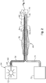
- Microsurgical instrument 46 may include an integrated fiber optic illuminator 52 for illuminating an interior of eye 20.
- fiber optic illuminator 48 may be optically connected to an illuminator 54 for producing light that may be used to illuminate vitreous region 38 of eye 20 during various intra-optical procedures, such as vitreoretinal surgery.
- Light produced by illuminator 54 may be transmitted to the interior region of the eye through an optical fiber 56.
- Optical fiber 56 may include a fiber optic connector 58 for optically connecting a proximal end 60 of optical fiber 56 to illuminator 54.
- Fiber optic connector 58 may be configured to releasably connect to a correspondingly configured illuminator optical connector operably associated with illuminator 54.
- optical fiber 56 may have any of a variety of configurations.
- optical fiber 56 includes an optically transmissive fiber optic core 62 surrounded by a cladding material 64 having a low index of refraction relative to core 62.
- Fiber optic core 62 may be made of various materials, including, but not limited to, glass and plastics.
- Optical fiber 56 may also include additional layers, depending on the requirements of a particular application.
- optical fiber 56 may include a buffer material encasing cladding material 64, as well as an outer protective jacket for shielding the cable's interior components from damage.
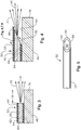
- a distal end 66 of optical fiber 56 may include an opening 68 for emitting light 70 produced by illuminator 54.
- illuminator 54 may employ a light source 72 for generating light at a particular luminous flux and chromaticity.
- the light may be emitted over a relatively wide or narrow range of wavelengths depending on the type of light source employed.
- Light source 72 may employ various light producing technologies, including, but not limited to, lamp based light sources, such as halogen tungsten lamps and high-pressure arc lamps (metal-halides and Xe).
- LEDs Light emitting diodes
- Lasers may also be employed as light source 72. Lasers are generally capable of producing light having a relatively high degree of coherence, as compared to other light sources, such as LEDs and lamp based light sources.
- Nano-scale optic fibers generally have a diameter (or other largest cross-sectional dimension) of less than 100 microns.
- microsurgical instrument 46 may be suitably connected to a service source 72, for example, via conduit 74.
- Service source 72 may be configured to provide various services used in connection with operating microsurgical instrument 46.
- Service source 72 may provide pressure and/or vacuum for operating microsurgical instrument 46. Vacuum may also be provided for aspirating fluids and materials from the interior of eye 20.
- Service source 72 may provide a source of fluids used in connection with the surgical procedure.
- Microsurgical instrument 46 may have various configurations depending on the surgical procedure performed. For example, certain ophthalmic surgical procedures may require the cutting and/or removal of vitreous region 38, which is a transparent jelly-like material that fills the posterior segment of eye 20. Vitrectomy probe 48 may be used to resect and remove the vitreous region.
- vitrectomy probe 48 may include a hollow outer cutting member, a hollow inner cutting member arranged coaxially with and movably disposed within the hollow outer cutting member, and a port extending radially through the outer cutting member near a distal end 76 thereof.
- Vitreous region 38 is aspirated into the open port, and the inner member is actuated to close the port and sever the vitreous material, which may then be aspirated away through conduit 74.
- the mechanism for actuating the hollow inner member may be enclosed within a housing 78, which may also function as a handle for grasping microsurgical instrument 46.
- Microsurgical instrument 46 may also be configured as infusion cannula 50 for delivering a fluid to the interior of eye 20. The fluid may be delivered to infusion cannula 50 through conduit 74.
- Conduit 74 may also be used to connect microsurgical instrument 46 to a vacuum source, for example, when configuring microsurgical instrument 46 as aspiration probe 51.
- light beam 70 emitted from fiber optic illuminator 52 it is generally desirable for light beam 70 emitted from fiber optic illuminator 52 to have a relatively wide angular distribution to enable illumination of a corresponding wide surgical field within eye 20.
- a portion of the light beam 70 emitted from optical fiber may be either absorbed or reflected from an adjacent outer surface 80 of microsurgical instrument 46, depending on the positioning of distal end 66 of optical fiber 56 relative to distal end 76 of microsurgical instrument 46. It may not always be desirable, however, to position distal end 66 of optical fiber 56 proximate to end 76 of microsurgical instrument 46.
- Positioning distal end 66 of optical fiber 56 a distance "D" from distal end 76 of microsurgical instrument 46 may, however, adversely affect the illuminating efficiency of fiber optic illuminator 52, particularly in instances in which a measurable portion of the emitted light is absorbed by outer surface 80 of microsurgical instrument 46.
- distal end 66 may be provided with a beveled end face 82 arranged at an oblique angle relative to an optical axis 84 of optical fiber 56.
- beveled end face need not refer strictly to a flat beveled surface but rather may include any configuration wherein a distalmost end face is arranged so that the surface normal, i.e., the axis perpendicular to the surface, is deviated to one side of the optical axis 84 over the majority of the end face, making the distalmost end face asymmetrical relative to the optical axis.
- the beveled end face 82 is said to "point” or to be “oriented” toward a certain direction, this refers to the side of the optical axis 84 toward which the beveled end face 82 is asymmetrically deviated.
- Inclining end face 82 relative to optical axis 84 generally results in light beam 70 approaching beveled end face 82 at an oblique incidence angle relative to the surface normal at the point of incidence.
- the transition between the two different refractive indices causes the light to refract as it transitions the interface between optical fiber 56 and vitreous region 38 of eye 20, thereby deflecting a propagation path 86 of light beam 70 away from optical axis 84 of optical fiber 56.
- the light beam 70 will tend to be refracted away from the surface normal of the beveled end surface 82, viz., ⁇ 2 > ⁇ 1 .
- the angular distribution of the rays in light beam 70 as the rays travel through the optical fiber 56 will therefore produce an angular distribution in the emitted light beam 70, which will be preferentially shifted away from the optical axis 84 of the optical fiber 56.
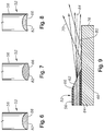
- beveled end face 82 is illustrated on an optical fiber 56 of uniform diameter, beveled end face 82 may also be used on a fiber optic with a tapered distal tip that narrows to a smaller width along a path that may includes curved or straight segments as the fiber optic extends toward the distal tip.
- the cladding may also be removed.
- the tapered distal end provides a wider angular distribution, which may advantageously be combined with the deflection produced by the beveled end face 82 to produce a wider illumination beam from the fiber optic selectively directed in a particular direction around the tip of the surgical instrument.
- the deflection of light beam 70 relative to microsurgical instrument 46 is at least partially dependent on the orientation of beveled end face 82 relative to microsurgical instrument 46. For example, orienting beveled end face 82 to point toward microsurgical instrument 46, such as shown in FIG. 4 , tends to shift propagation path 86 of the light beam away from microsurgical instrument 46. On the other hand, orienting beveled end face 82 to point away from microsurgical instrument 46, such as shown in FIG. 9 , tends to shift the propagation path 86 of light beam 70 toward microsurgical instrument 46. Referring to FIG. 9 , fiber optic illuminator 52 is shown with beveled end face 82 oriented to face generally away from microsurgical instrument 46.
- This arrangement generally results in propagation path 86 of light beam 70 being shifted toward microsurgical instrument 46.
- this arrangement increases, rather than decreases, the amount of light reflected from microsurgical instrument 46.
- a wider dispersion of light emitted from optical fiber may be obtained by enhancing the reflectivity of outer surface 80 of microsurgical instrument 46.
- Light emitted from optical fiber 56 may be reflected from surface 80 of microsurgical instrument 46 to provide a broader distribution of light within an interior region of eye 20.
- FIGS. 6-8 are partial cross-sectional views taken through beveled end face 82 ( see FIG. 4 ) along a perspective generally parallel to end face 82.
- Beveled end face 82 may include a variety of surface contours.
- FIG. 6 shows beveled end face 82 configured to include a planar surface.
- Beveled end face 82 may alternatively be configured to include a generally convex surface contour, such as shown in FIG. 7 .
- Beveled end face 82 may also have a generally concave configuration, as shown in FIG. 8 .
- These are merely a few examples of the various surface contours that may be employed with beveled end face 82. In practice, other contours may also be employed to accommodate design and performance requirements of a particular application.
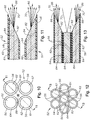
- fiber optic illuminator 52 may be configured to include multiple bundled optical fibers 56 surrounding a distal tip of a microsurgical instrument 46.
- FIG. 10 shows an exemplary arrangement including four optical fibers 56 bundled together. Each optical fiber may include a beveled end face 82 for selectively controlling a propagation path of emitted light.
- beveled end face 82 of optical fibers 56 positioned at opposite corners of the cable bundle are shown oriented so as to generally face one another. This particular arrangement tends to increase the dispersion of the emitted light by shifting propagation path 86 of light beam 70 outward from a center axis 88 of the bundle.
- FIGS. 12 and 13 show an exemplary optical fiber bundle including seven optical fibers 56.
- the optical fibers are shown arranged generally in a hexagonal pattern, with six optical fibers positioned around a center optical fiber.
- Each of the outer optical fibers 56 may include a beveled end face 82 for selectively controlling a propagation path of emitted light.
- the single center optical fiber 56 in this exemplary configuration does not include a beveled end face.
- Beveled end faces 82 of the outer optical fibers 56 may be oriented so as to generally point radially inward toward a center of the optical fiber bundle. This particular arrangement tends to increase the dispersion of the light emitted from the outer optical fibers by shifting propagation path 86 of light beam 70 outward from the center of the optical fiber bundle.
- the distal end of the entire bundle is placed proximate to a distal tip of a microsurgical instrument 46.
- the central fiber optical cable and/or the optical fibers that are more remote from the distal tip of the microsurgical instrument 46 can have a flat surface so that the propagation path of light emitted from the center optical fiber tends to coincide with optical axis of the optical fiber.
- light emitted from the center optical fiber 56 may fill a light void that may exist between the light beams emitted from the surrounding outer optical fibers 56, while still allowing the overall amount of reflected light from the distal tip of the microsurgical instrument 46 to be reduced by the orientation of the closest optical fibers 56.
- the depicted orientation of the beveled end faces 82 can advantageously provide additional illumination through reflection, as previously illustrated in FIG. 9 .
- the beveled end faces 82 could be reversed to point toward the distal tip of microsurgical instrument 46, preferentially shifting the illumination away from the distal tip of microsurgical instrument 46, as illustrated in FIG. 4 .
- the optical fibers 56 can be placed in a similar configuration as illustrated in FIGS. 10-13 , but centered around the distal tip of microsurgical instrument 56, so as to produce illumination from multiple optical fibers 56 around the microsurgical instrument 56.
Landscapes
- Health & Medical Sciences (AREA)
- Life Sciences & Earth Sciences (AREA)
- Physics & Mathematics (AREA)
- Surgery (AREA)
- Heart & Thoracic Surgery (AREA)
- General Health & Medical Sciences (AREA)
- Veterinary Medicine (AREA)
- Engineering & Computer Science (AREA)
- Animal Behavior & Ethology (AREA)
- Biomedical Technology (AREA)
- Public Health (AREA)
- Ophthalmology & Optometry (AREA)
- Nuclear Medicine, Radiotherapy & Molecular Imaging (AREA)
- Vascular Medicine (AREA)
- Optics & Photonics (AREA)
- General Physics & Mathematics (AREA)
- Molecular Biology (AREA)
- Medical Informatics (AREA)
- Oral & Maxillofacial Surgery (AREA)
- Pathology (AREA)
- Anesthesiology (AREA)
- Hematology (AREA)
- Biophysics (AREA)
- Astronomy & Astrophysics (AREA)
- Laser Surgery Devices (AREA)
- Non-Portable Lighting Devices Or Systems Thereof (AREA)
- Radiation-Therapy Devices (AREA)
Priority Applications (1)
| Application Number | Priority Date | Filing Date | Title |
|---|---|---|---|
| PL15179907T PL2975440T3 (pl) | 2011-05-06 | 2012-04-30 | Oświetlony instrument mikrochirurgiczny zawierający światłowód ze skośną powierzchnią końcową |
Applications Claiming Priority (2)
| Application Number | Priority Date | Filing Date | Title |
|---|---|---|---|
| US201161483224P | 2011-05-06 | 2011-05-06 | |
| EP12721077.1A EP2681596B1 (en) | 2011-05-06 | 2012-04-30 | Illuminated microsurgical instrument including optical fiber with beveled end face |
Related Parent Applications (2)
| Application Number | Title | Priority Date | Filing Date |
|---|---|---|---|
| EP12721077.1A Division-Into EP2681596B1 (en) | 2011-05-06 | 2012-04-30 | Illuminated microsurgical instrument including optical fiber with beveled end face |
| EP12721077.1A Division EP2681596B1 (en) | 2011-05-06 | 2012-04-30 | Illuminated microsurgical instrument including optical fiber with beveled end face |
Publications (2)
| Publication Number | Publication Date |
|---|---|
| EP2975440A1 EP2975440A1 (en) | 2016-01-20 |
| EP2975440B1 true EP2975440B1 (en) | 2018-06-20 |
Family
ID=46085192
Family Applications (2)
| Application Number | Title | Priority Date | Filing Date |
|---|---|---|---|
| EP12721077.1A Active EP2681596B1 (en) | 2011-05-06 | 2012-04-30 | Illuminated microsurgical instrument including optical fiber with beveled end face |
| EP15179907.9A Active EP2975440B1 (en) | 2011-05-06 | 2012-04-30 | Illuminated microsurgical instrument including optical fiber with beveled end face |
Family Applications Before (1)
| Application Number | Title | Priority Date | Filing Date |
|---|---|---|---|
| EP12721077.1A Active EP2681596B1 (en) | 2011-05-06 | 2012-04-30 | Illuminated microsurgical instrument including optical fiber with beveled end face |
Country Status (22)
| Country | Link |
|---|---|
| US (2) | US8900139B2 (pt) |
| EP (2) | EP2681596B1 (pt) |
| JP (2) | JP5856289B2 (pt) |
| KR (1) | KR101631654B1 (pt) |
| CN (1) | CN103502856B (pt) |
| AR (1) | AR086028A1 (pt) |
| AU (1) | AU2012253984B2 (pt) |
| BR (1) | BR112013028490A2 (pt) |
| CA (1) | CA2832502C (pt) |
| CY (1) | CY1116906T1 (pt) |
| DK (2) | DK2681596T3 (pt) |
| ES (2) | ES2549781T3 (pt) |
| HR (1) | HRP20151365T8 (pt) |
| HU (1) | HUE026940T2 (pt) |
| MX (1) | MX338378B (pt) |
| PL (2) | PL2975440T3 (pt) |
| PT (2) | PT2681596E (pt) |
| RS (1) | RS54335B1 (pt) |
| SI (1) | SI2681596T1 (pt) |
| SM (1) | SMT201600032B (pt) |
| TW (1) | TWI561204B (pt) |
| WO (1) | WO2012154435A1 (pt) |
Families Citing this family (41)
| Publication number | Priority date | Publication date | Assignee | Title |
|---|---|---|---|---|
| US9402643B2 (en) | 2008-01-15 | 2016-08-02 | Novartis Ag | Targeted illumination for surgical instrument |
| WO2012021451A1 (en) * | 2010-08-09 | 2012-02-16 | Alcon Research, Ltd. | Illuminated surgical instrument |
| US20150150723A1 (en) * | 2011-03-23 | 2015-06-04 | Mindskid Labs, Llc | Eye Marker Tip |
| US9849034B2 (en) | 2011-11-07 | 2017-12-26 | Alcon Research, Ltd. | Retinal laser surgery |
| AU2013359241B2 (en) * | 2012-12-12 | 2017-10-26 | Invuity, Inc. | Illuminated suction apparatus |
| DE102014223304A1 (de) * | 2014-03-11 | 2015-09-17 | Geuder Ag | chirurgisches Instrument |
| US10039669B2 (en) * | 2014-10-24 | 2018-08-07 | Novartis Ag | Internally illuminated surgical probe |
| US10238543B2 (en) * | 2014-10-29 | 2019-03-26 | Novartis Ag | Vitrectomy probe with an optical fiber scanner |
| IL237995A0 (en) * | 2015-03-29 | 2015-11-30 | Abraham Aharoni | Device for visual detection of veins |
| US10244931B2 (en) * | 2015-07-13 | 2019-04-02 | Novartis Ag | Illuminated ophthalmic infusion line and associated devices, systems, and methods |
| CA2989278A1 (en) * | 2015-07-13 | 2017-01-19 | Novartis Ag | Vitreous cutter with integrated illumination system |
| US11173008B2 (en) | 2015-11-01 | 2021-11-16 | Alcon Inc. | Illuminated ophthalmic cannula |
| ES2778687T3 (es) * | 2015-12-14 | 2020-08-11 | Alcon Inc | Aparatos quirúrgicos de calibre híbrido de un solo orificio |
| US10016248B2 (en) * | 2015-12-17 | 2018-07-10 | Novartis Ag | Ophthalmic illumination profiles and associated devices, systems, and methods |
| US9956053B2 (en) | 2016-03-04 | 2018-05-01 | Novartis Ag | Cannula with an integrated illumination feature |
| PL3245931T3 (pl) | 2016-05-18 | 2019-04-30 | Oertli Instr Ag | Magnetyczne złącze z wtyczką dla światłowodu |
| US20170333151A1 (en) * | 2016-05-20 | 2017-11-23 | H.S. International Corp. | Wide angle illumination system and method |
| CN109496259A (zh) | 2016-08-25 | 2019-03-19 | 诺华股份有限公司 | 用于眼科手术的平面照明器 |
| CN109906065A (zh) * | 2016-11-17 | 2019-06-18 | 诺华股份有限公司 | 具有集成光纤的医疗器械 |
| US11110005B2 (en) * | 2016-11-17 | 2021-09-07 | Alcon Inc. | Medical instrument with an integrated optical fiber |
| WO2018091992A1 (en) * | 2016-11-21 | 2018-05-24 | Novartis Ag | Systems and methods using a vitreous visualization tool |
| EP3554434B1 (en) | 2016-12-15 | 2021-08-11 | Alcon Inc. | Illuminated surgical probe having a variable illumination numerical aperture |
| WO2018109579A1 (en) * | 2016-12-15 | 2018-06-21 | Novartis Ag | Illuminated surgical probe having multiple optical fibers |
| CA3051536A1 (en) * | 2017-02-02 | 2018-08-09 | Novartis Ag | Focusing optics for mixed mode surgical laser illumination |
| EP3589208A1 (en) * | 2017-03-02 | 2020-01-08 | Circuit Therapeutics, Inc. | System for optogenetic therapy |
| WO2018197651A1 (de) * | 2017-04-26 | 2018-11-01 | Pharmpur Gmbh | Vorrichtung zur beleuchtung des intraokularen raumes |
| WO2018215954A1 (en) | 2017-05-24 | 2018-11-29 | Novartis Ag | Illuminated infusion cannula |
| EP3630026A1 (en) | 2017-05-24 | 2020-04-08 | Alcon Inc. | Illuminated infusion cannula |
| US10918522B2 (en) | 2017-06-08 | 2021-02-16 | Alcon Inc. | Photodisruption-based vitrectomy system |
| BR112020002441A2 (pt) | 2017-08-09 | 2020-07-28 | Alcon Inc. | dispositivo de cânula microcirúrgico autoiluminante |
| WO2019097338A1 (en) | 2017-11-14 | 2019-05-23 | Novartis Ag | Multi-spot laser probe with illumination features |
| WO2019175784A1 (en) * | 2018-03-14 | 2019-09-19 | Alcon Inc. | Medical instruments with adjustable optical fiber |
| US11471242B1 (en) | 2018-03-14 | 2022-10-18 | Alcon Inc. | Medical instruments with an integrated optical fiber and methods of manufacture |
| WO2019197993A1 (en) | 2018-04-11 | 2019-10-17 | Alcon Inc. | Illuminating ophthalmic endoprobe |
| CN108338812A (zh) * | 2018-04-17 | 2018-07-31 | 四川大学华西医院 | 一种冷光源引导缝合器 |
| US11395713B2 (en) | 2018-07-19 | 2022-07-26 | Alcon Inc. | Illuminated cannula |
| US11489311B2 (en) * | 2019-10-22 | 2022-11-01 | Lumentum Operations Llc | Optical amplifier |
| US20220133139A1 (en) * | 2020-11-02 | 2022-05-05 | Vanderbilt University | System and method for surgery guidance |
| US20220347015A1 (en) * | 2021-05-03 | 2022-11-03 | VisionCare Devices LLC. | Vitrector Cutting Device with Distal Illumination Module |
| JP2024528837A (ja) | 2021-08-06 | 2024-08-01 | アルコン インコーポレイティド | 照明、流体吸引及び光凝固のための硝子体網膜器具 |
| US11826033B2 (en) * | 2021-09-16 | 2023-11-28 | Xrv-Ip, Llc | Illuminated scleral depressor assembly |
Family Cites Families (38)
| Publication number | Priority date | Publication date | Assignee | Title |
|---|---|---|---|---|
| JPS5210346Y1 (pt) * | 1968-04-22 | 1977-03-05 | ||
| JPS5942700B2 (ja) * | 1975-07-14 | 1984-10-17 | 三菱化成ポリテック株式会社 | 無機質充填剤配合オレフイン系樹脂組成物 |
| US4607622A (en) | 1985-04-11 | 1986-08-26 | Charles D. Fritch | Fiber optic ocular endoscope |
| EP0260856A2 (en) | 1986-09-19 | 1988-03-23 | Baxter Travenol Laboratories, Inc. | Distortion corrected endoscope |
| FR2610511A1 (fr) * | 1987-02-06 | 1988-08-12 | Issalene Robert | Instrument dentaire et canules pour aspirer, nettoyer, secher et eclairer dans la bouche |
| US5201730A (en) * | 1989-10-24 | 1993-04-13 | Surgical Technologies, Inc. | Tissue manipulator for use in vitreous surgery combining a fiber optic endoilluminator with an infusion/aspiration system |
| US5280788A (en) * | 1991-02-26 | 1994-01-25 | Massachusetts Institute Of Technology | Devices and methods for optical diagnosis of tissue |
| CA2066963A1 (en) * | 1991-05-15 | 1992-11-16 | Norio Daikuzono | Laser light irradiation apparatus |
| US5357168A (en) | 1991-09-17 | 1994-10-18 | Goldstar Co., Ltd. | Magnetron having a cathode with tapered end shields |
| US5402508A (en) * | 1993-05-04 | 1995-03-28 | The United States Of America As Represented By The United States Department Of Energy | Fiber optic probe having fibers with endfaces formed for improved coupling efficiency and method using same |
| US5588952A (en) * | 1993-08-02 | 1996-12-31 | Dandolu; Bhaktavathsala R. | Intracardiac illuminator with suction |
| CH687295A5 (de) | 1993-11-10 | 1996-11-15 | Volpi Ag | Ophtalmoskopische Beleuchtungssonde. |
| US5554155A (en) * | 1994-06-03 | 1996-09-10 | Johns Hopkins University | Fiber optic pick manipulator |
| US5681264A (en) | 1995-10-25 | 1997-10-28 | Ryan, Jr.; Edwin H. | Shielded illumination device for ophthalmic surgery and the like |
| US5916149A (en) | 1995-10-25 | 1999-06-29 | Ryan, Jr.; Edwin H. | Shielded illumination device for ophthalmic surgery and the like |
| US6174424B1 (en) * | 1995-11-20 | 2001-01-16 | Cirrex Corp. | Couplers for optical fibers |
| US5785645A (en) | 1996-04-16 | 1998-07-28 | Synergetics, Inc. | Beveled tip illuminator for microsurgery |
| US5931670A (en) * | 1996-10-29 | 1999-08-03 | Davis; James M. | Illuminated dental suction appliance |
| RU2130762C1 (ru) | 1997-12-10 | 1999-05-27 | Федоров Святослав Николаевич | Устройство для офтальмохирургических операций |
| US5964747A (en) * | 1998-03-23 | 1999-10-12 | Duke University | Lighting instrument, in particular for use in ophthalmologic microsurgery |
| WO2001019255A1 (en) * | 1999-09-13 | 2001-03-22 | Synergetics, Inc. | Adjustable stiffness membrane scraper |
| MXPA03006394A (es) * | 2001-01-18 | 2003-10-15 | Univ California | Instrumento quirurgico paraglaucoma minimamente invasivo y metodo. |
| JP2002245821A (ja) | 2001-02-14 | 2002-08-30 | Mitsubishi Rayon Co Ltd | 光ファイバ照射体 |
| US8491549B2 (en) | 2001-11-21 | 2013-07-23 | Iscience Interventional Corporation | Ophthalmic microsurgical system |
| EP1686910B1 (en) * | 2003-11-13 | 2015-08-12 | Synergetics, Inc. | Illuminated laser probe with adjustble area of illumination |
| CN2668087Y (zh) * | 2003-12-18 | 2005-01-05 | 江门新会新希望眼科医院 | 带输液套管的导光纤维管 |
| US9675235B2 (en) * | 2005-03-21 | 2017-06-13 | Jonas V. Lieponis | Multi-purpose surgical instrument with removable component |
| US7618177B2 (en) * | 2005-04-29 | 2009-11-17 | Alcon, Inc. | Multi-fiber variable intensity wide-angle illuminator |
| DE202005008788U1 (de) * | 2005-05-27 | 2006-08-10 | Karl Storz Gmbh & Co. Kg | Endoskop, insbesondere für die Tracheotomie |
| AU2006308884B2 (en) * | 2005-10-31 | 2012-07-05 | Alcon Inc. | Surgical variable-angle illuminator |
| BRPI0618268A2 (pt) * | 2005-10-31 | 2011-08-23 | Alcon Inc | iluminador cirúrgico de ángulo largo |
| JP4997364B2 (ja) * | 2006-03-29 | 2012-08-08 | 並木精密宝石株式会社 | 光照射プローブ |
| US20080108983A1 (en) * | 2006-11-07 | 2008-05-08 | Synergetics, Inc. | Dual Core Optic Fiber Illuminated Laser Probe |
| US20110125139A1 (en) | 2007-10-04 | 2011-05-26 | Auld Jack R | Multi-fiber flexible surgical probe |
| US9402643B2 (en) | 2008-01-15 | 2016-08-02 | Novartis Ag | Targeted illumination for surgical instrument |
| US8488930B2 (en) * | 2010-12-09 | 2013-07-16 | Alcon Research, Ltd. | Wavelength converting illumination probe |
| US20120203075A1 (en) * | 2011-02-08 | 2012-08-09 | Christopher Horvath | White coherent laser light launched into nano fibers for surgical illumination |
| WO2012162493A2 (en) * | 2011-05-24 | 2012-11-29 | Jeffrey Brennan | Scanning endoscopic imaging probes and related methods |
-
2012
- 2012-04-12 TW TW101113000A patent/TWI561204B/zh not_active IP Right Cessation
- 2012-04-17 AR ARP120101313A patent/AR086028A1/es unknown
- 2012-04-30 AU AU2012253984A patent/AU2012253984B2/en not_active Ceased
- 2012-04-30 PL PL15179907T patent/PL2975440T3/pl unknown
- 2012-04-30 CN CN201280022006.8A patent/CN103502856B/zh not_active Expired - Fee Related
- 2012-04-30 PT PT127210771T patent/PT2681596E/pt unknown
- 2012-04-30 RS RS20150699A patent/RS54335B1/en unknown
- 2012-04-30 SI SI201230393T patent/SI2681596T1/sl unknown
- 2012-04-30 HU HUE12721077A patent/HUE026940T2/en unknown
- 2012-04-30 US US13/459,629 patent/US8900139B2/en active Active
- 2012-04-30 KR KR1020137031810A patent/KR101631654B1/ko active IP Right Grant
- 2012-04-30 EP EP12721077.1A patent/EP2681596B1/en active Active
- 2012-04-30 CA CA2832502A patent/CA2832502C/en not_active Expired - Fee Related
- 2012-04-30 ES ES12721077.1T patent/ES2549781T3/es active Active
- 2012-04-30 PL PL12721077T patent/PL2681596T3/pl unknown
- 2012-04-30 MX MX2013012117A patent/MX338378B/es active IP Right Grant
- 2012-04-30 JP JP2014509335A patent/JP5856289B2/ja active Active
- 2012-04-30 EP EP15179907.9A patent/EP2975440B1/en active Active
- 2012-04-30 DK DK12721077.1T patent/DK2681596T3/en active
- 2012-04-30 DK DK15179907.9T patent/DK2975440T3/en active
- 2012-04-30 PT PT151799079T patent/PT2975440T/pt unknown
- 2012-04-30 BR BR112013028490A patent/BR112013028490A2/pt not_active Application Discontinuation
- 2012-04-30 ES ES15179907.9T patent/ES2682363T3/es active Active
- 2012-04-30 WO PCT/US2012/035774 patent/WO2012154435A1/en active Application Filing
-
2014
- 2014-11-26 US US14/554,419 patent/US9561085B2/en active Active
-
2015
- 2015-11-10 CY CY20151101003T patent/CY1116906T1/el unknown
- 2015-12-10 HR HRP20151365TT patent/HRP20151365T8/hr unknown
- 2015-12-10 JP JP2015241183A patent/JP6189916B2/ja active Active
-
2016
- 2016-02-04 SM SM201600032T patent/SMT201600032B/it unknown
Non-Patent Citations (1)
| Title |
|---|
| None * |
Also Published As
Similar Documents
| Publication | Publication Date | Title |
|---|---|---|
| EP2975440B1 (en) | Illuminated microsurgical instrument including optical fiber with beveled end face | |
| AU2012253984A1 (en) | Illuminated microsurgical instrument including optical fiber with beveled end face | |
| EP2648639B1 (en) | White coherent laser light launched into nano fibers for surgical illumination | |
| AU2008348095B2 (en) | Targeted illumination for surgical instrument | |
| AU2011289406B2 (en) | Dual-mode illumination for surgical instrument | |
| RU2575051C2 (ru) | Микрохирургический инструмент с подсветкой, включающий в себя оптическое волокно со скошенной торцевой поверхностью |
Legal Events
| Date | Code | Title | Description |
|---|---|---|---|
| PUAI | Public reference made under article 153(3) epc to a published international application that has entered the european phase |
Free format text: ORIGINAL CODE: 0009012 |
|
| AC | Divisional application: reference to earlier application |
Ref document number: 2681596 Country of ref document: EP Kind code of ref document: P |
|
| AK | Designated contracting states |
Kind code of ref document: A1 Designated state(s): AL AT BE BG CH CY CZ DE DK EE ES FI FR GB GR HR HU IE IS IT LI LT LU LV MC MK MT NL NO PL PT RO RS SE SI SK SM TR |
|
| RIN1 | Information on inventor provided before grant (corrected) |
Inventor name: LASSALAS, BRUNO Inventor name: YADLOWSKY, MICHAEL J. Inventor name: PAPAC, MICHAEL JAMES |
|
| 17P | Request for examination filed |
Effective date: 20160707 |
|
| RBV | Designated contracting states (corrected) |
Designated state(s): AL AT BE BG CH CY CZ DE DK EE ES FI FR GB GR HR HU IE IS IT LI LT LU LV MC MK MT NL NO PL PT RO RS SE SI SK SM TR |
|
| GRAP | Despatch of communication of intention to grant a patent |
Free format text: ORIGINAL CODE: EPIDOSNIGR1 |
|
| STAA | Information on the status of an ep patent application or granted ep patent |
Free format text: STATUS: GRANT OF PATENT IS INTENDED |
|
| INTG | Intention to grant announced |
Effective date: 20180221 |
|
| GRAS | Grant fee paid |
Free format text: ORIGINAL CODE: EPIDOSNIGR3 |
|
| GRAA | (expected) grant |
Free format text: ORIGINAL CODE: 0009210 |
|
| STAA | Information on the status of an ep patent application or granted ep patent |
Free format text: STATUS: THE PATENT HAS BEEN GRANTED |
|
| AC | Divisional application: reference to earlier application |
Ref document number: 2681596 Country of ref document: EP Kind code of ref document: P |
|
| AK | Designated contracting states |
Kind code of ref document: B1 Designated state(s): AL AT BE BG CH CY CZ DE DK EE ES FI FR GB GR HR HU IE IS IT LI LT LU LV MC MK MT NL NO PL PT RO RS SE SI SK SM TR |
|
| REG | Reference to a national code |
Ref country code: GB Ref legal event code: FG4D |
|
| REG | Reference to a national code |
Ref country code: IE Ref legal event code: FG4D |
|
| REG | Reference to a national code |
Ref country code: DE Ref legal event code: R096 Ref document number: 602012047759 Country of ref document: DE |
|
| REG | Reference to a national code |
Ref country code: AT Ref legal event code: REF Ref document number: 1011006 Country of ref document: AT Kind code of ref document: T Effective date: 20180715 |
|
| REG | Reference to a national code |
Ref country code: PT Ref legal event code: SC4A Ref document number: 2975440 Country of ref document: PT Date of ref document: 20180808 Kind code of ref document: T Free format text: AVAILABILITY OF NATIONAL TRANSLATION Effective date: 20180801 |
|
| REG | Reference to a national code |
Ref country code: ES Ref legal event code: FG2A Ref document number: 2682363 Country of ref document: ES Kind code of ref document: T3 Effective date: 20180920 |
|
| REG | Reference to a national code |
Ref country code: DK Ref legal event code: T3 Effective date: 20180924 |
|
| REG | Reference to a national code |
Ref country code: NL Ref legal event code: FP |
|
| PG25 | Lapsed in a contracting state [announced via postgrant information from national office to epo] |
Ref country code: SE Free format text: LAPSE BECAUSE OF FAILURE TO SUBMIT A TRANSLATION OF THE DESCRIPTION OR TO PAY THE FEE WITHIN THE PRESCRIBED TIME-LIMIT Effective date: 20180620 Ref country code: LT Free format text: LAPSE BECAUSE OF FAILURE TO SUBMIT A TRANSLATION OF THE DESCRIPTION OR TO PAY THE FEE WITHIN THE PRESCRIBED TIME-LIMIT Effective date: 20180620 Ref country code: NO Free format text: LAPSE BECAUSE OF FAILURE TO SUBMIT A TRANSLATION OF THE DESCRIPTION OR TO PAY THE FEE WITHIN THE PRESCRIBED TIME-LIMIT Effective date: 20180920 Ref country code: BG Free format text: LAPSE BECAUSE OF FAILURE TO SUBMIT A TRANSLATION OF THE DESCRIPTION OR TO PAY THE FEE WITHIN THE PRESCRIBED TIME-LIMIT Effective date: 20180920 Ref country code: FI Free format text: LAPSE BECAUSE OF FAILURE TO SUBMIT A TRANSLATION OF THE DESCRIPTION OR TO PAY THE FEE WITHIN THE PRESCRIBED TIME-LIMIT Effective date: 20180620 |
|
| REG | Reference to a national code |
Ref country code: LT Ref legal event code: MG4D |
|
| PG25 | Lapsed in a contracting state [announced via postgrant information from national office to epo] |
Ref country code: RS Free format text: LAPSE BECAUSE OF FAILURE TO SUBMIT A TRANSLATION OF THE DESCRIPTION OR TO PAY THE FEE WITHIN THE PRESCRIBED TIME-LIMIT Effective date: 20180620 Ref country code: HR Free format text: LAPSE BECAUSE OF FAILURE TO SUBMIT A TRANSLATION OF THE DESCRIPTION OR TO PAY THE FEE WITHIN THE PRESCRIBED TIME-LIMIT Effective date: 20180620 Ref country code: LV Free format text: LAPSE BECAUSE OF FAILURE TO SUBMIT A TRANSLATION OF THE DESCRIPTION OR TO PAY THE FEE WITHIN THE PRESCRIBED TIME-LIMIT Effective date: 20180620 |
|
| REG | Reference to a national code |
Ref country code: AT Ref legal event code: MK05 Ref document number: 1011006 Country of ref document: AT Kind code of ref document: T Effective date: 20180620 |
|
| PG25 | Lapsed in a contracting state [announced via postgrant information from national office to epo] |
Ref country code: AT Free format text: LAPSE BECAUSE OF FAILURE TO SUBMIT A TRANSLATION OF THE DESCRIPTION OR TO PAY THE FEE WITHIN THE PRESCRIBED TIME-LIMIT Effective date: 20180620 Ref country code: IS Free format text: LAPSE BECAUSE OF FAILURE TO SUBMIT A TRANSLATION OF THE DESCRIPTION OR TO PAY THE FEE WITHIN THE PRESCRIBED TIME-LIMIT Effective date: 20181020 Ref country code: SK Free format text: LAPSE BECAUSE OF FAILURE TO SUBMIT A TRANSLATION OF THE DESCRIPTION OR TO PAY THE FEE WITHIN THE PRESCRIBED TIME-LIMIT Effective date: 20180620 Ref country code: EE Free format text: LAPSE BECAUSE OF FAILURE TO SUBMIT A TRANSLATION OF THE DESCRIPTION OR TO PAY THE FEE WITHIN THE PRESCRIBED TIME-LIMIT Effective date: 20180620 Ref country code: RO Free format text: LAPSE BECAUSE OF FAILURE TO SUBMIT A TRANSLATION OF THE DESCRIPTION OR TO PAY THE FEE WITHIN THE PRESCRIBED TIME-LIMIT Effective date: 20180620 Ref country code: CZ Free format text: LAPSE BECAUSE OF FAILURE TO SUBMIT A TRANSLATION OF THE DESCRIPTION OR TO PAY THE FEE WITHIN THE PRESCRIBED TIME-LIMIT Effective date: 20180620 |
|
| REG | Reference to a national code |
Ref country code: GR Ref legal event code: EP Ref document number: 20180402633 Country of ref document: GR Effective date: 20190125 |
|
| PG25 | Lapsed in a contracting state [announced via postgrant information from national office to epo] |
Ref country code: SM Free format text: LAPSE BECAUSE OF FAILURE TO SUBMIT A TRANSLATION OF THE DESCRIPTION OR TO PAY THE FEE WITHIN THE PRESCRIBED TIME-LIMIT Effective date: 20180620 |
|
| REG | Reference to a national code |
Ref country code: DE Ref legal event code: R097 Ref document number: 602012047759 Country of ref document: DE |
|
| PLBE | No opposition filed within time limit |
Free format text: ORIGINAL CODE: 0009261 |
|
| STAA | Information on the status of an ep patent application or granted ep patent |
Free format text: STATUS: NO OPPOSITION FILED WITHIN TIME LIMIT |
|
| 26N | No opposition filed |
Effective date: 20190321 |
|
| PGFP | Annual fee paid to national office [announced via postgrant information from national office to epo] |
Ref country code: BE Payment date: 20190326 Year of fee payment: 8 Ref country code: GR Payment date: 20190329 Year of fee payment: 8 |
|
| PGFP | Annual fee paid to national office [announced via postgrant information from national office to epo] |
Ref country code: NL Payment date: 20190412 Year of fee payment: 8 |
|
| PGFP | Annual fee paid to national office [announced via postgrant information from national office to epo] |
Ref country code: DK Payment date: 20190410 Year of fee payment: 8 Ref country code: PL Payment date: 20190402 Year of fee payment: 8 Ref country code: ES Payment date: 20190503 Year of fee payment: 8 Ref country code: PT Payment date: 20190429 Year of fee payment: 8 Ref country code: IT Payment date: 20190419 Year of fee payment: 8 |
|
| PG25 | Lapsed in a contracting state [announced via postgrant information from national office to epo] |
Ref country code: SI Free format text: LAPSE BECAUSE OF FAILURE TO SUBMIT A TRANSLATION OF THE DESCRIPTION OR TO PAY THE FEE WITHIN THE PRESCRIBED TIME-LIMIT Effective date: 20180620 |
|
| PGFP | Annual fee paid to national office [announced via postgrant information from national office to epo] |
Ref country code: TR Payment date: 20190412 Year of fee payment: 8 |
|
| PGFP | Annual fee paid to national office [announced via postgrant information from national office to epo] |
Ref country code: CH Payment date: 20190416 Year of fee payment: 8 |
|
| REG | Reference to a national code |
Ref country code: NL Ref legal event code: PD Owner name: ALCON INC.; CH Free format text: DETAILS ASSIGNMENT: CHANGE OF OWNER(S), MERGE; FORMER OWNER NAME: ALCON RESEARCH, LTD. Effective date: 20191031 |
|
| PG25 | Lapsed in a contracting state [announced via postgrant information from national office to epo] |
Ref country code: AL Free format text: LAPSE BECAUSE OF FAILURE TO SUBMIT A TRANSLATION OF THE DESCRIPTION OR TO PAY THE FEE WITHIN THE PRESCRIBED TIME-LIMIT Effective date: 20180620 |
|
| REG | Reference to a national code |
Ref country code: CH Ref legal event code: PUE Owner name: ALCON INC., CH Free format text: FORMER OWNER: ALCON RESEARCH, LTD., US |
|
| PG25 | Lapsed in a contracting state [announced via postgrant information from national office to epo] |
Ref country code: LU Free format text: LAPSE BECAUSE OF NON-PAYMENT OF DUE FEES Effective date: 20190430 Ref country code: MC Free format text: LAPSE BECAUSE OF FAILURE TO SUBMIT A TRANSLATION OF THE DESCRIPTION OR TO PAY THE FEE WITHIN THE PRESCRIBED TIME-LIMIT Effective date: 20180620 |
|
| REG | Reference to a national code |
Ref country code: GB Ref legal event code: 732E Free format text: REGISTERED BETWEEN 20200109 AND 20200115 |
|
| REG | Reference to a national code |
Ref country code: GB Ref legal event code: 732E Free format text: REGISTERED BETWEEN 20200116 AND 20200122 |
|
| REG | Reference to a national code |
Ref country code: BE Ref legal event code: PD Owner name: ALCON INC.; CH Free format text: DETAILS ASSIGNMENT: CHANGE OF OWNER(S), FUSION Effective date: 20191127 |
|
| REG | Reference to a national code |
Ref country code: DE Ref legal event code: R081 Ref document number: 602012047759 Country of ref document: DE Owner name: ALCON INC., CH Free format text: FORMER OWNER: ALCON RESEARCH, LTD., FORT WORTH, TEX., US |
|
| REG | Reference to a national code |
Ref country code: ES Ref legal event code: PC2A Owner name: ALCON INC. Effective date: 20200407 |
|
| PG25 | Lapsed in a contracting state [announced via postgrant information from national office to epo] |
Ref country code: IE Free format text: LAPSE BECAUSE OF NON-PAYMENT OF DUE FEES Effective date: 20190430 |
|
| REG | Reference to a national code |
Ref country code: DK Ref legal event code: EBP Effective date: 20200430 |
|
| REG | Reference to a national code |
Ref country code: CH Ref legal event code: PL |
|
| REG | Reference to a national code |
Ref country code: NL Ref legal event code: MM Effective date: 20200501 |
|
| PG25 | Lapsed in a contracting state [announced via postgrant information from national office to epo] |
Ref country code: CH Free format text: LAPSE BECAUSE OF NON-PAYMENT OF DUE FEES Effective date: 20200430 Ref country code: LI Free format text: LAPSE BECAUSE OF NON-PAYMENT OF DUE FEES Effective date: 20200430 Ref country code: PT Free format text: LAPSE BECAUSE OF NON-PAYMENT OF DUE FEES Effective date: 20201102 Ref country code: GR Free format text: LAPSE BECAUSE OF NON-PAYMENT OF DUE FEES Effective date: 20201109 |
|
| REG | Reference to a national code |
Ref country code: BE Ref legal event code: MM Effective date: 20200430 |
|
| PG25 | Lapsed in a contracting state [announced via postgrant information from national office to epo] |
Ref country code: BE Free format text: LAPSE BECAUSE OF NON-PAYMENT OF DUE FEES Effective date: 20200430 |
|
| PG25 | Lapsed in a contracting state [announced via postgrant information from national office to epo] |
Ref country code: NL Free format text: LAPSE BECAUSE OF NON-PAYMENT OF DUE FEES Effective date: 20200501 |
|
| PG25 | Lapsed in a contracting state [announced via postgrant information from national office to epo] |
Ref country code: DK Free format text: LAPSE BECAUSE OF NON-PAYMENT OF DUE FEES Effective date: 20200430 |
|
| PG25 | Lapsed in a contracting state [announced via postgrant information from national office to epo] |
Ref country code: CY Free format text: LAPSE BECAUSE OF FAILURE TO SUBMIT A TRANSLATION OF THE DESCRIPTION OR TO PAY THE FEE WITHIN THE PRESCRIBED TIME-LIMIT Effective date: 20180620 |
|
| PG25 | Lapsed in a contracting state [announced via postgrant information from national office to epo] |
Ref country code: HU Free format text: LAPSE BECAUSE OF FAILURE TO SUBMIT A TRANSLATION OF THE DESCRIPTION OR TO PAY THE FEE WITHIN THE PRESCRIBED TIME-LIMIT; INVALID AB INITIO Effective date: 20120430 Ref country code: MT Free format text: LAPSE BECAUSE OF FAILURE TO SUBMIT A TRANSLATION OF THE DESCRIPTION OR TO PAY THE FEE WITHIN THE PRESCRIBED TIME-LIMIT Effective date: 20180620 |
|
| REG | Reference to a national code |
Ref country code: ES Ref legal event code: FD2A Effective date: 20210906 |
|
| PG25 | Lapsed in a contracting state [announced via postgrant information from national office to epo] |
Ref country code: IT Free format text: LAPSE BECAUSE OF NON-PAYMENT OF DUE FEES Effective date: 20200430 |
|
| PG25 | Lapsed in a contracting state [announced via postgrant information from national office to epo] |
Ref country code: ES Free format text: LAPSE BECAUSE OF NON-PAYMENT OF DUE FEES Effective date: 20200501 |
|
| PG25 | Lapsed in a contracting state [announced via postgrant information from national office to epo] |
Ref country code: TR Free format text: LAPSE BECAUSE OF NON-PAYMENT OF DUE FEES Effective date: 20200430 Ref country code: MK Free format text: LAPSE BECAUSE OF FAILURE TO SUBMIT A TRANSLATION OF THE DESCRIPTION OR TO PAY THE FEE WITHIN THE PRESCRIBED TIME-LIMIT Effective date: 20180620 |
|
| PG25 | Lapsed in a contracting state [announced via postgrant information from national office to epo] |
Ref country code: PL Free format text: LAPSE BECAUSE OF NON-PAYMENT OF DUE FEES Effective date: 20200430 |
|
| P01 | Opt-out of the competence of the unified patent court (upc) registered |
Effective date: 20230504 |
|
| PGFP | Annual fee paid to national office [announced via postgrant information from national office to epo] |
Ref country code: DE Payment date: 20230321 Year of fee payment: 12 |
|
| PGFP | Annual fee paid to national office [announced via postgrant information from national office to epo] |
Ref country code: GB Payment date: 20240321 Year of fee payment: 13 |
|
| PGFP | Annual fee paid to national office [announced via postgrant information from national office to epo] |
Ref country code: FR Payment date: 20240321 Year of fee payment: 13 |