EP2648639B1 - White coherent laser light launched into nano fibers for surgical illumination - Google Patents
White coherent laser light launched into nano fibers for surgical illumination Download PDFInfo
- Publication number
- EP2648639B1 EP2648639B1 EP11858160.2A EP11858160A EP2648639B1 EP 2648639 B1 EP2648639 B1 EP 2648639B1 EP 11858160 A EP11858160 A EP 11858160A EP 2648639 B1 EP2648639 B1 EP 2648639B1
- Authority
- EP
- European Patent Office
- Prior art keywords
- surgical
- light beam
- light
- illumination
- fiber optic
- Prior art date
- Legal status (The legal status is an assumption and is not a legal conclusion. Google has not performed a legal analysis and makes no representation as to the accuracy of the status listed.)
- Active
Links
Images


Classifications
-
- A—HUMAN NECESSITIES
- A61—MEDICAL OR VETERINARY SCIENCE; HYGIENE
- A61B—DIAGNOSIS; SURGERY; IDENTIFICATION
- A61B1/00—Instruments for performing medical examinations of the interior of cavities or tubes of the body by visual or photographical inspection, e.g. endoscopes; Illuminating arrangements therefor
- A61B1/06—Instruments for performing medical examinations of the interior of cavities or tubes of the body by visual or photographical inspection, e.g. endoscopes; Illuminating arrangements therefor with illuminating arrangements
- A61B1/07—Instruments for performing medical examinations of the interior of cavities or tubes of the body by visual or photographical inspection, e.g. endoscopes; Illuminating arrangements therefor with illuminating arrangements using light-conductive means, e.g. optical fibres
-
- A—HUMAN NECESSITIES
- A61—MEDICAL OR VETERINARY SCIENCE; HYGIENE
- A61F—FILTERS IMPLANTABLE INTO BLOOD VESSELS; PROSTHESES; DEVICES PROVIDING PATENCY TO, OR PREVENTING COLLAPSING OF, TUBULAR STRUCTURES OF THE BODY, e.g. STENTS; ORTHOPAEDIC, NURSING OR CONTRACEPTIVE DEVICES; FOMENTATION; TREATMENT OR PROTECTION OF EYES OR EARS; BANDAGES, DRESSINGS OR ABSORBENT PADS; FIRST-AID KITS
- A61F9/00—Methods or devices for treatment of the eyes; Devices for putting in contact-lenses; Devices to correct squinting; Apparatus to guide the blind; Protective devices for the eyes, carried on the body or in the hand
- A61F9/007—Methods or devices for eye surgery
-
- A—HUMAN NECESSITIES
- A61—MEDICAL OR VETERINARY SCIENCE; HYGIENE
- A61B—DIAGNOSIS; SURGERY; IDENTIFICATION
- A61B3/00—Apparatus for testing the eyes; Instruments for examining the eyes
- A61B3/0008—Apparatus for testing the eyes; Instruments for examining the eyes provided with illuminating means
-
- A—HUMAN NECESSITIES
- A61—MEDICAL OR VETERINARY SCIENCE; HYGIENE
- A61B—DIAGNOSIS; SURGERY; IDENTIFICATION
- A61B90/00—Instruments, implements or accessories specially adapted for surgery or diagnosis and not covered by any of the groups A61B1/00 - A61B50/00, e.g. for luxation treatment or for protecting wound edges
- A61B90/30—Devices for illuminating a surgical field, the devices having an interrelation with other surgical devices or with a surgical procedure
-
- A—HUMAN NECESSITIES
- A61—MEDICAL OR VETERINARY SCIENCE; HYGIENE
- A61F—FILTERS IMPLANTABLE INTO BLOOD VESSELS; PROSTHESES; DEVICES PROVIDING PATENCY TO, OR PREVENTING COLLAPSING OF, TUBULAR STRUCTURES OF THE BODY, e.g. STENTS; ORTHOPAEDIC, NURSING OR CONTRACEPTIVE DEVICES; FOMENTATION; TREATMENT OR PROTECTION OF EYES OR EARS; BANDAGES, DRESSINGS OR ABSORBENT PADS; FIRST-AID KITS
- A61F9/00—Methods or devices for treatment of the eyes; Devices for putting in contact-lenses; Devices to correct squinting; Apparatus to guide the blind; Protective devices for the eyes, carried on the body or in the hand
- A61F9/007—Methods or devices for eye surgery
- A61F9/008—Methods or devices for eye surgery using laser
-
- A—HUMAN NECESSITIES
- A61—MEDICAL OR VETERINARY SCIENCE; HYGIENE
- A61B—DIAGNOSIS; SURGERY; IDENTIFICATION
- A61B90/00—Instruments, implements or accessories specially adapted for surgery or diagnosis and not covered by any of the groups A61B1/00 - A61B50/00, e.g. for luxation treatment or for protecting wound edges
- A61B90/30—Devices for illuminating a surgical field, the devices having an interrelation with other surgical devices or with a surgical procedure
- A61B2090/306—Devices for illuminating a surgical field, the devices having an interrelation with other surgical devices or with a surgical procedure using optical fibres
Definitions
- an eye may be divided into two distinct parts - an anterior segment and a posterior segment.
- the anterior segment includes a lens and extends from an outermost layer of the cornea (the corneal endothelium) to a posterior of a lens capsule.
- the posterior segment includes a portion of the eye behind the lens capsule.
- the posterior segment extends from an anterior hyaloid face (part of a vitreous body) to a retina, with which the posterior hyaloid face is in direct contact.
- the posterior segment is much larger than the anterior segment.
- the posterior segment includes the vitreous body - a clear, colorless, gel-like substance. It makes up approximately two-thirds of the eye's volume, giving it form and shape before birth.
- the vitreous body is composed of 1% collagen and sodium hyaluronate and 99% water.
- the anterior boundary of the vitreous body is the anterior hyaloid face, which touches the posterior capsule of the lens, while the posterior hyaloid face forms its posterior boundary, and is in contact with the retina.
- the vitreous body is not free flowing like the aqueous humor and has normal anatomic attachment sites. One of these sites is the vitreous base, which is an approximately 3-4 mm wide band that overlies the ora serrata.
- the optic nerve head, macula lutea, and vascular arcade are also sites of attachment.
- the vitreous body's major functions are to hold the retina in place, maintain the integrity and shape of the globe, absorb shock due to movement, and to give support for the lens posteriorly.
- the vitreous body is not continuously replaced.
- the vitreous body becomes more fluid with age in a process known as syneresis. Syneresis results in shrinkage of the vitreous body, which can exert pressure or traction on its normal attachment sites. If enough traction is applied, the vitreous body may pull itself from its retinal attachment and create a retinal tear or hole.
- Vitreo-retinal procedures are commonly performed in the posterior segment of the eye. Vitreo-retinal procedures are appropriate to treat many serious conditions of the posterior segment. Vitreo-retinal procedures treat conditions such as age-related macular degeneration (AMD), diabetic retinopathy and diabetic vitreous hemorrhage, macular hole, retinal detachment, epiretinal membrane, CMV retinitis, and many other ophthalmic conditions.
- AMD age-related macular degeneration
- diabetic retinopathy and diabetic vitreous hemorrhage macular hole
- retinal detachment epiretinal membrane
- CMV retinitis CMV retinitis
- a surgeon performs vitreo-retinal procedures with a microscope and special lenses designed to provide a clear image of the posterior segment. Several tiny incisions just a millimeter or so in length are made on the sclera at the pars plana. The surgeon inserts microsurgical instruments through the incisions, such as a fiber optic light source, to illuminate inside the eye; an infusion line to maintain the eye's shape during surgery; and instruments to cut and remove the vitreous body. A separate incision may be provided for each microsurgical instrument when using multiple instruments simultaneously.
- a thin optical fiber is inserted into the eye to provide the illumination.
- a light source such as a halogen tungsten lamp or high pressure arc lamp (metal-halides, Xe), may be used to produce the light carried by the optical fiber into the eye.
- the light passes through several optical elements (typically lenses, mirrors, and attenuators) and is transmitted to the optical fiber that carries the light into the eye.
- incisions are typically only made large enough to accommodate the size of the microsurgical instrument being inserted into the interior of the eye.
- Efforts to minimize the incision size generally involve reducing the size of the microsurgical instrument.
- Reducing the number of incisions may be accomplished by integrating various microsurgical instruments.
- the optical fiber may be incorporated into the working end of a microsurgical instrument. This may eliminate the need for a separate illumination incision and offers the advantage of directing the light beam together with the microsurgical instrument onto the target site through a common opening in the sclera.
- at least some prior attempts at integrating multiple microsurgical instruments resulted larger instruments requiring larger incisions for insertion into the interior region of the eye, or were accompanied by a corresponding decrease in performance of one or both of the integrated surgical instruments.
- EP 1114608 discloses the features of the preamble of claim 1.
- the present invention provides a surgical illumination system in accordance with claims which follow.
- FIG. 1 illustrates an anatomy of an eye 20, which includes a cornea 22, an iris 24, a pupil 26, a lens 28, a lens capsule 30, zonules 32, ciliary body 34, sclera 36, vitreous region 38, retina 40, macula 42, and optic nerve 44.
- Cornea 22 is a clear, dome shaped structure on the surface of eye 20 that acts as a window, letting light into the eye.
- Iris 24, which corresponds to the colored part of the eye, is a muscle surrounding pupil 26 that relaxes and contracts to control the amount of light entering eye 20.
- Pupil 26 is a round, central opening in iris 24.
- Lens 28 is a structure inside eye 20 that helps focus light on retina 40.
- Lens capsule 30 is an elastic bag that encapsulates lens 30, helping to control the shape of lens 28 as the eye focuses on objects at different distances.
- Zonules 32 are slender ligaments that attach lens capsule 30 to the inside of eye 20, holding lens 28 in place.
- Ciliary body 34 is a muscular area attached to lens 28 that contracts and relaxes to control the size of the lens for focusing.
- Sclera 36 is a tough, outermost layer of eye 20 that maintains the shape of the eye.
- Vitreous region 38 is a large, gel-filled section located towards a back of eye 20 that helps maintain the curvature of the eye.
- Retina 40 is a light-sensitive nerve layer at the back of eye 20 that receives light and converts it into signals to send to the brain.
- Macula 42 is an area in the back of eye 20 that includes receptors for detecting fine detail in a viewed image.
- Optic nerve 44 transmits signals from eye 20 to the brain.
- various microsurgical instruments may be inserted through sclera 36 (generally at the pars plana) into vitreous region 38 in connection with performing a vitreo-retinal procedure.
- sclera 36 generally at the pars plana
- these may include, but are not limited to, a vitrectomy probe 46, an infusion cannula 48, and an illumination probe 50 for illuminating an interior of eye 20.
- Illumination probe 50 may include a fiber optic cable 52 for transferring light from a light source to illuminate the inside of vitreous region 38 of eye 20 during various intraoperative procedures, such as vitreo-retinal surgery.
- an exemplary endoilluminator 51 may include an illuminator 52 and illumination probe 50.
- Illuminator 52 may include a light engine 54 for generating light at a particular luminous flux and chromaticity. Light produced by illuminator 52 may be transmitted to the interior region of the eye through illumination probe 50.
- Light engine 54 may employ a laser 56 for generating the light.
- lasers Various types and configurations of lasers may be employed, including but not limited to, gas lasers, dye lasers, metal vapor lasers, solid state lasers, semiconductor lasers, fiber lasers, and supercontinuum lasers. The light may be emitted from laser 56 over a relatively wide or narrow spectral range depending on the type of laser employed.
- Lasers are generally capable of producing light having a relatively high degree of spatial coherence, as compared to other light sources, such as LEDs and lamp based illuminators.
- High spatial coherence enables the emitted light to be focused to smaller spot sizes for efficient transmission to fiber optic cables.
- the ability to focus the emitted light to small spot sizes may enable the use of small optic fibers, such as nano-scaled optic fibers, which may in turn allow for smaller surgical incisions for inserting illumination probe 50 into eye 20.
- small optic fibers such as nano-scaled optic fibers, which may in turn allow for smaller surgical incisions for inserting illumination probe 50 into eye 20.
- small optic fibers such as nano-scaled optic fibers
- Smaller optic fibers generally require smaller surgical incisions for insertion into the eye.
- the incision may be small enough to render the resulting wound substantially self-healing, thereby eliminating the need to employ additional procedures to close the incision, such as sutures.
- Laser 56 may be configured to produce a generally broadband white light for illuminating the interior region of eye 20.
- laser 56 may be configured as a supercontinuum laser capable of producing a generally broadband light over a relatively wide spectral range.
- Supercontinuum lasers operate, for example, by passing a generally narrow bandwidth pulsed pump beam through a dispersive, non-linear medium, such as a photonic crystal fiber. As the pump beam propagates through the dispersive, non-linear medium, a series of non-linear processes act upon the pump beam to cause spectral broadening of the initial pump beam. The result is a spectral continuum extending over at least a portion of the visible spectrum.
- Laser 56 may also be configured to emit light covering the entire visible spectrum and extending into portions of the invisible spectrum.
- illuminator 52 may include various devices for controlling and monitoring the operation of laser 56, including but not limited to, drive electronics 58, power monitor 60, and controller 62.
- Power monitor 60 may be configured to monitor the power of a light beam 64 emitted from laser 56.
- a beam splitter 66, or another suitable optical device, may be used to direct a portion 68 of light beam 64 to power monitor 60.
- Power monitor 60 may be configured to generate an electronic signal indicative of the power of the light emitted from laser 56.
- Power monitor 60 may be electronically connected, either wired or wirelessly, to controller 62.
- Controller 62 may at least partly control the operation of drive electronics 58.
- Various informational inputs may be received by controller 62, including but not limited to, various user inputs and the power signal transmitted from power monitor 60, and then heuristics, i.e., logical rules or processes, may be applied to the inputs. Outputs may then be generated that influence operation of drive electronics 58 in the context of the overall operation of illuminator 52.
- Dispersive element 70 may be configured as a length of dispersive optic fiber.
- Dispersive element 70 may include an optical coupler 71 for selectively optically coupling illumination probe 50 to illuminator 52. Alternatively, dispersive element may be integrated as part of illumination probe 50.
- illuminator 52 may include an optical coupler 72 for capturing and focusing light beam 64 emitted from laser 56, and focusing the light for delivery to dispersive element 70.
- Optical coupler 72 may include various optical elements, such as, for example, a collimating lens 74 for receiving the generally divergent light beam 64 emitted from laser 56, and a condensing lens 76 arranged optically downstream of collimating lens 74.
- Collimating lens 74 receives light beam 64 emitted from laser 56, and refracts the light to form a generally collimated light beam 77.
- Collimated light beam 77 passes through condensing lens 76, which operates to focus the collimated light beam for delivery to dispersive element 70.
- Optical coupler 72 may alternatively employ a ball lens for optically coupling laser 56 to dispersive element 70. These are just two examples of the various optical coupling systems that may be employed to optically couple laser 56 to fiber optic cable 52. Other optical coupling systems may also be utilized.
- illumination probe 50 may include a fiber optic cable 78 for transmitting light emitted from laser 56 to the interior of eye 20.
- Fiber optic cable 78 may include a fiber optic connector 80 for optically connecting fiber optic cable 78 to dispersive element 70.
- Fiber optic connector 80 releasably connects to correspondingly configured optical coupler 71 operably associated with illuminator 52.
- Optical connectors 71 and 80 enable fiber optic cable 78 to be selectively attached and detached from illuminator 52.
- fiber optic cable 78 is shown directly connected to dispersive element 70.
- illuminator 52 may be housed within a surgical console.
- An optical connector configured similar to optical coupler 71, may be arranged in a readily accessible location on the surgical console to provide access for optically connecting fiber optic cable 78 to the connector.
- a series of optical elements such as an additional length of optical fiber (which may be permanent or disposable), may be employed to optically connect illuminator 52 to the optical connector arranged on the outside of the surgical console.
- Other optical elements may also be employed for optically connecting fiber optic cable 78 to illuminator 52.
- Fiber optic cable 78 may have any of a variety of configurations.
- Fiber optic cable 78 may include a flexible configuration to allow generally unimpeded manipulation of illumination probe 50.
- Fiber optic cable 78 may include an optically transmissive fiber optic core 82 surrounded by a cladding material 84 having a generally low index of refraction relative to fiber optic core 82.
- Fiber optic core 82 may be made of various materials, including but not limited to, glass and plastics.
- Fiber optic cable 78 may also include additional layers depending on the requirements of a particular application.
- fiber optic cable 78 may include a buffer material encasing cladding material 84, as well as an outer protective jacket (such as a plastic or metal tube) for shielding the cable's interior components from damage.
- the emitted light beam 64 When employing a supercontinuum laser as laser 56, the emitted light beam 64 generally possesses a high degree of spatial coherence. High spatial coherence typically enables the beam to be focused to small spot sizes for delivery to fiber optic cabling. The ability to focus light emitted from a supercontinuum laser to small spot sizes may enable the use of nano-scale optic fibers for transmitting the light emitted from laser 56 to the interior of eye 20. Nano-scale optic fibers generally have a diameter (or other largest cross-sectional dimension) of less than 100 microns.
- the small diameter of nano-scale optic fiber may enable a reduction in the cross-sectional area of the probe, which in turn may reduce the size of the surgical incision in sclera 36 of eye 20 (see FIGS. 1 and 2 ) though which the probe is inserted.
- an exemplary configured integrated illumination probe/infusion cannula 86 may include a nano-scale fiber optic cable 88 for transmitting light emitted from laser 56 to the interior of eye 20.
- a hose 90 may be provided for transporting liquid or gas for delivery to the interior of eye 20.
- a hub 92 interconnects nano-scale fiber optic cable 88 with hose 90.
- a cannula 94 may be attached to hub 92.
- Cannula 94 provides a passage for receiving an end 96 of nano-scale fiber optic cable 88, and for delivering the fluid or gas to the interior of eye 20.
- Nano-scale fiber optic cable 88 and hose 90 may be enclosed in a protective sheath 98.
- the exemplary configuration of integrated illumination probe/infusion cannula 86 enables the two surgical instruments to simultaneously access the interior region of eye 20 through a single surgical incision.
- Nano-scale fiber optic cable 88 may be similarly integrated with other microsurgical instruments.
- an endoilluminator 100 may include an alternately configured light engine 102 for generating light at a particular luminous flux and chromaticity.
- Light engine 102 may be similarly configured as light engine 54 (see FIG. 3 ), but differs by including multiple lasers for generating a generally broadband white light for illuminating an interior of eye 20.
- endoilluminator 100 is similarly configured as endoilluminator 52 illustrated in FIG. 3 .
- light engine 102 of endoilluminator 100 utilizes two or more lasers to produce light having selected spectral properties.
- light engine 102 includes four lasers 104, 106, 108 and 110. Each laser may be configured to generate light over a different portion of the desired spectral range.
- a beam combiner 112 may be provided for combining the light beams emitted from the individual lasers into a single light beam 64 having a desired spectral range.
- Light beam 64 will have a spectral range that includes the spectral ranges of the light beams emitted from lasers 104, 106, 108 and 110.
- Four lasers are shown in the exemplarily configuration of endoilluminator 100, as illustrated in FIG. 3 , but in S practice, fewer or more lasers may be employed.
- the actual number of lasers employed will depend at least in part on the wavelength range of the individual lasers. Generally, the broader the spectral range the fewer number of lasers that will need to be employed to produce light across a desired spectral range. Although each laser produces light over a different spectral range, it may be beneficial to have at least some overlap between the spectral ranges to help insure a uniform spectral distribution of the emitted light.
- a light beam produced by combining multiple individual light beams to produce a single light beam having the spectral ranges of the individual light beams, such as implemented with light engine 102, may be subject to a phenomenon referred to as speckling.
- Speckling occurs when multiple light waves having different phases interfere with one another. When added together, the interferences produce a light wave having an intensity that varies randomly.
- Options for reducing speckling include, for example, using rotating diffusers or lenses arranged in the optical path of light beam 64 to disrupt the spatial coherence of the emitted laser light.
- Other options include passing the summed light beam through a vibrating or stretched coil of optic fiber, such as second dispersive element 70, to produce a uniform illumination.
- light emitted from illumination probe 50 may have a relatively wide angular distribution to enable illumination of corresponding wide surgical field within eye 20.
- Light emitted from nano-scale optic fibers such as may be employed with fiber optic cable 78, may have a relatively small angular distribution due to the small numerical aperture of the fiber or the small numerical aperture of the beam within the fiber.
- one option for achieving a wider angular distribution of emitted light is to selectively taper an end 114 of fiber optic core 82.
- Various tapers may be employed, such as a compound parabolic concentrator, depending on the design parameters of a particular application and the angular distribution desired.
- Alternative methods such as adding a diffusing agent to the end of the fiber optic may be used to create a larger illumination angle.
- the angular distribution of light emitted from fiber optic cable 78 may also be increased by employing a fiber optic cable having a high numerical aperture.
- a high numerical aperture indicates a large difference in refractive index between fiber optic core 82 and cladding 84.
- Fiber optic cables having large numerical apertures can generally accept light over a broader range of incident angles than fiber optic cables having smaller numerical apertures.
- Increasing an incidence angle 116 at which light enters fiber optic cable 78 generally results in an increase in the angular distribution of light emitted from the fiber optic cable.
- Increasing the numerical aperture of fiber optic cable 78 when employed in conjunction with an increased incidence angle of the light delivered to the fiber optic cable, may improve the angular distribution of light emitted from illumination probe 50.
- photodarkening may occur.
- Photodarkening is a multiphoton process, and the probability of its occurrence is proportional to the peak power of a pulse.
- a pulse stretching element in the optical train may alleviate this condition.
- a pulse stretching element may stretch a 100 to 200 picosecond (ps) pulse to 1 nanosecond (ns).
- ns nanosecond
- a temporally dispersive element may also accomplish this.
Landscapes
- Health & Medical Sciences (AREA)
- Life Sciences & Earth Sciences (AREA)
- Surgery (AREA)
- Engineering & Computer Science (AREA)
- Animal Behavior & Ethology (AREA)
- Veterinary Medicine (AREA)
- Biomedical Technology (AREA)
- Heart & Thoracic Surgery (AREA)
- Public Health (AREA)
- General Health & Medical Sciences (AREA)
- Ophthalmology & Optometry (AREA)
- Medical Informatics (AREA)
- Molecular Biology (AREA)
- Nuclear Medicine, Radiotherapy & Molecular Imaging (AREA)
- Physics & Mathematics (AREA)
- Biophysics (AREA)
- Pathology (AREA)
- Optics & Photonics (AREA)
- Vascular Medicine (AREA)
- Oral & Maxillofacial Surgery (AREA)
- Radiology & Medical Imaging (AREA)
- Laser Surgery Devices (AREA)
Description
- Anatomically, an eye may be divided into two distinct parts - an anterior segment and a posterior segment. The anterior segment includes a lens and extends from an outermost layer of the cornea (the corneal endothelium) to a posterior of a lens capsule. The posterior segment includes a portion of the eye behind the lens capsule. The posterior segment extends from an anterior hyaloid face (part of a vitreous body) to a retina, with which the posterior hyaloid face is in direct contact. The posterior segment is much larger than the anterior segment.
- The posterior segment includes the vitreous body - a clear, colorless, gel-like substance. It makes up approximately two-thirds of the eye's volume, giving it form and shape before birth. The vitreous body is composed of 1% collagen and sodium hyaluronate and 99% water. The anterior boundary of the vitreous body is the anterior hyaloid face, which touches the posterior capsule of the lens, while the posterior hyaloid face forms its posterior boundary, and is in contact with the retina. The vitreous body is not free flowing like the aqueous humor and has normal anatomic attachment sites. One of these sites is the vitreous base, which is an approximately 3-4 mm wide band that overlies the ora serrata. The optic nerve head, macula lutea, and vascular arcade are also sites of attachment. The vitreous body's major functions are to hold the retina in place, maintain the integrity and shape of the globe, absorb shock due to movement, and to give support for the lens posteriorly. In contrast to the aqueous humor, the vitreous body is not continuously replaced. The vitreous body becomes more fluid with age in a process known as syneresis. Syneresis results in shrinkage of the vitreous body, which can exert pressure or traction on its normal attachment sites. If enough traction is applied, the vitreous body may pull itself from its retinal attachment and create a retinal tear or hole.
- Various surgical procedures, called vitreo-retinal procedures, are commonly performed in the posterior segment of the eye. Vitreo-retinal procedures are appropriate to treat many serious conditions of the posterior segment. Vitreo-retinal procedures treat conditions such as age-related macular degeneration (AMD), diabetic retinopathy and diabetic vitreous hemorrhage, macular hole, retinal detachment, epiretinal membrane, CMV retinitis, and many other ophthalmic conditions.
- A surgeon performs vitreo-retinal procedures with a microscope and special lenses designed to provide a clear image of the posterior segment. Several tiny incisions just a millimeter or so in length are made on the sclera at the pars plana. The surgeon inserts microsurgical instruments through the incisions, such as a fiber optic light source, to illuminate inside the eye; an infusion line to maintain the eye's shape during surgery; and instruments to cut and remove the vitreous body. A separate incision may be provided for each microsurgical instrument when using multiple instruments simultaneously.
- During such surgical procedures, proper illumination of the inside of the eye is important. Typically, a thin optical fiber is inserted into the eye to provide the illumination. A light source, such as a halogen tungsten lamp or high pressure arc lamp (metal-halides, Xe), may be used to produce the light carried by the optical fiber into the eye. The light passes through several optical elements (typically lenses, mirrors, and attenuators) and is transmitted to the optical fiber that carries the light into the eye.
- As with most surgical procedures, there is a benefit to minimizing the number and size of incisions required to perform the vitreo-retinal procedure. Incisions are typically only made large enough to accommodate the size of the microsurgical instrument being inserted into the interior of the eye. Efforts to minimize the incision size generally involve reducing the size of the microsurgical instrument. Reducing the number of incisions may be accomplished by integrating various microsurgical instruments. For example, the optical fiber may be incorporated into the working end of a microsurgical instrument. This may eliminate the need for a separate illumination incision and offers the advantage of directing the light beam together with the microsurgical instrument onto the target site through a common opening in the sclera. Unfortunately, at least some prior attempts at integrating multiple microsurgical instruments resulted larger instruments requiring larger incisions for insertion into the interior region of the eye, or were accompanied by a corresponding decrease in performance of one or both of the integrated surgical instruments.
-
-
EP 1114608 discloses the features of the preamble of claim 1. - The present invention provides a surgical illumination system in accordance with claims which follow.
-
-
FIG. 1 is a cross-sectional view of an eye illustrating an internal anatomy of the eye; -
FIG. 2 is schematic illustration of an exemplary illumination probe shown illuminating an interior region of the eye ofFIG. 1 ; -
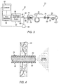
FIG. 3 is a schematic illustration of an exemplary intraocular illumination system employing a generally broadband laser light source that may be selectively optically connected to the illumination probe; -
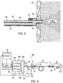
FIG. 4 is a schematic partial cross-sectional view of an end of the illumination probe shown projecting through an incision in a sclera of the eye; -
FIG. 5 is a schematic partial cross-sectional view of an exemplary integrated infusion cannula and illumination probe that may be employed with the intraocular illumination systems ofFIGS. 3 and6 ; -
FIG. 6 is a schematic illustration of an exemplary intraocular illumination system employing multiple narrowband lasers as the light source; -
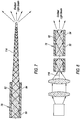
FIG. 7 is a schematic partial cross-sectional view of an exemplary illumination probe that may be employed with the intraocular illumination systems ofFIGS. 3 and6 , the illumination probe including a nano-scale optical fiber having a shaped end for selectively tailoring the distribution of light emitted from the illumination probe; and -
FIG. 8 is a schematic partial cross-sectional view of an exemplary illumination probe including a high numerical aperture and a nano-scale optical illumination fiber that may be employed with the intraocular illumination systems ofFIGS. 3 and6 . - Referring now to the discussion that follows and the drawings, illustrative approaches to the disclosed systems and methods are described in detail. Although the drawings represent some possible approaches, the drawings are not necessarily to scale and certain features may be exaggerated, removed, or partially sectioned to better illustrate and explain the present disclosure. Further, the descriptions set forth herein are not intended to be exhaustive, otherwise limit, or restrict the claims to the precise forms and configurations shown in the drawings and disclosed in the following detailed description.
-
FIG. 1 illustrates an anatomy of aneye 20, which includes acornea 22, aniris 24, apupil 26, alens 28, alens capsule 30,zonules 32,ciliary body 34,sclera 36,vitreous region 38,retina 40,macula 42, andoptic nerve 44.Cornea 22 is a clear, dome shaped structure on the surface ofeye 20 that acts as a window, letting light into the eye.Iris 24, which corresponds to the colored part of the eye, is amuscle surrounding pupil 26 that relaxes and contracts to control the amount oflight entering eye 20.Pupil 26 is a round, central opening iniris 24.Lens 28 is a structure insideeye 20 that helps focus light onretina 40.Lens capsule 30 is an elastic bag that encapsulateslens 30, helping to control the shape oflens 28 as the eye focuses on objects at different distances. Zonules 32 are slender ligaments that attachlens capsule 30 to the inside ofeye 20, holdinglens 28 in place.Ciliary body 34 is a muscular area attached tolens 28 that contracts and relaxes to control the size of the lens for focusing.Sclera 36 is a tough, outermost layer ofeye 20 that maintains the shape of the eye.Vitreous region 38 is a large, gel-filled section located towards a back ofeye 20 that helps maintain the curvature of the eye. Retina 40 is a light-sensitive nerve layer at the back ofeye 20 that receives light and converts it into signals to send to the brain. Macula 42 is an area in the back ofeye 20 that includes receptors for detecting fine detail in a viewed image.Optic nerve 44 transmits signals fromeye 20 to the brain. - With reference to
FIG. 2 , various microsurgical instruments may be inserted through sclera 36 (generally at the pars plana) intovitreous region 38 in connection with performing a vitreo-retinal procedure. These may include, but are not limited to, avitrectomy probe 46, aninfusion cannula 48, and anillumination probe 50 for illuminating an interior ofeye 20.Illumination probe 50 may include afiber optic cable 52 for transferring light from a light source to illuminate the inside ofvitreous region 38 ofeye 20 during various intraoperative procedures, such as vitreo-retinal surgery. - With reference to
FIG. 3 , anexemplary endoilluminator 51 may include anilluminator 52 andillumination probe 50.Illuminator 52 may include alight engine 54 for generating light at a particular luminous flux and chromaticity. Light produced byilluminator 52 may be transmitted to the interior region of the eye throughillumination probe 50.Light engine 54 may employ alaser 56 for generating the light. Various types and configurations of lasers may be employed, including but not limited to, gas lasers, dye lasers, metal vapor lasers, solid state lasers, semiconductor lasers, fiber lasers, and supercontinuum lasers. The light may be emitted fromlaser 56 over a relatively wide or narrow spectral range depending on the type of laser employed. Lasers are generally capable of producing light having a relatively high degree of spatial coherence, as compared to other light sources, such as LEDs and lamp based illuminators. High spatial coherence enables the emitted light to be focused to smaller spot sizes for efficient transmission to fiber optic cables. The ability to focus the emitted light to small spot sizes may enable the use of small optic fibers, such as nano-scaled optic fibers, which may in turn allow for smaller surgical incisions for insertingillumination probe 50 intoeye 20. As is the case with many surgical procedures, including vitreo-retinal procedures, it is generally desirable to limit surgical incisions to as small a size as possible. Smaller optic fibers generally require smaller surgical incisions for insertion into the eye. Depending on the size of the optic fiber employed, the incision may be small enough to render the resulting wound substantially self-healing, thereby eliminating the need to employ additional procedures to close the incision, such as sutures. -
Laser 56 may be configured to produce a generally broadband white light for illuminating the interior region ofeye 20. For example,laser 56 may be configured as a supercontinuum laser capable of producing a generally broadband light over a relatively wide spectral range. Supercontinuum lasers operate, for example, by passing a generally narrow bandwidth pulsed pump beam through a dispersive, non-linear medium, such as a photonic crystal fiber. As the pump beam propagates through the dispersive, non-linear medium, a series of non-linear processes act upon the pump beam to cause spectral broadening of the initial pump beam. The result is a spectral continuum extending over at least a portion of the visible spectrum.Laser 56 may also be configured to emit light covering the entire visible spectrum and extending into portions of the invisible spectrum. - Continuing to refer to
FIG. 3 ,illuminator 52 may include various devices for controlling and monitoring the operation oflaser 56, including but not limited to, driveelectronics 58,power monitor 60, andcontroller 62. Power monitor 60 may be configured to monitor the power of alight beam 64 emitted fromlaser 56. Abeam splitter 66, or another suitable optical device, may be used to direct aportion 68 oflight beam 64 topower monitor 60. Power monitor 60 may be configured to generate an electronic signal indicative of the power of the light emitted fromlaser 56. Power monitor 60 may be electronically connected, either wired or wirelessly, tocontroller 62. -
Controller 62 may at least partly control the operation ofdrive electronics 58. Various informational inputs may be received bycontroller 62, including but not limited to, various user inputs and the power signal transmitted frompower monitor 60, and then heuristics, i.e., logical rules or processes, may be applied to the inputs. Outputs may then be generated that influence operation ofdrive electronics 58 in the context of the overall operation ofilluminator 52. - In certain illumination applications, such as when employing a supercontinuum laser, it may be beneficial to further stretch the beam pulses emitted from
laser 56 in the time domain. This may be accomplished by arranging adispersive element 70 in the optical path downstream of the dispersive, non-linear medium used to generate the generally broadband white light emitted fromlaser 56.Dispersive element 70 may be configured as a length of dispersive optic fiber.Dispersive element 70 may include anoptical coupler 71 for selectively optically couplingillumination probe 50 toilluminator 52. Alternatively, dispersive element may be integrated as part ofillumination probe 50. - Continuing to refer to
FIG. 3 ,illuminator 52 may include anoptical coupler 72 for capturing and focusinglight beam 64 emitted fromlaser 56, and focusing the light for delivery to dispersiveelement 70.Optical coupler 72 may include various optical elements, such as, for example, a collimatinglens 74 for receiving the generallydivergent light beam 64 emitted fromlaser 56, and a condensinglens 76 arranged optically downstream of collimatinglens 74. Collimatinglens 74 receiveslight beam 64 emitted fromlaser 56, and refracts the light to form a generally collimatedlight beam 77. Collimatedlight beam 77 passes through condensinglens 76, which operates to focus the collimated light beam for delivery to dispersiveelement 70.Optical coupler 72 may alternatively employ a ball lens for optically couplinglaser 56 to dispersiveelement 70. These are just two examples of the various optical coupling systems that may be employed to optically couplelaser 56 tofiber optic cable 52. Other optical coupling systems may also be utilized. - With continued reference to
FIG. 3 ,illumination probe 50 may include afiber optic cable 78 for transmitting light emitted fromlaser 56 to the interior ofeye 20.Fiber optic cable 78 may include afiber optic connector 80 for optically connectingfiber optic cable 78 to dispersiveelement 70.Fiber optic connector 80 releasably connects to correspondingly configuredoptical coupler 71 operably associated withilluminator 52.Optical connectors fiber optic cable 78 to be selectively attached and detached fromilluminator 52. In the exemplary configuration ofendoilluminator 51 illustrated inFIG. 3 ,fiber optic cable 78 is shown directly connected to dispersiveelement 70. In practice, various additional optical elements may be disposed in the optical path betweenilluminator 52 andfiber optic cable 78. For example,illuminator 52 may be housed within a surgical console. An optical connector, configured similar tooptical coupler 71, may be arranged in a readily accessible location on the surgical console to provide access for optically connectingfiber optic cable 78 to the connector. A series of optical elements, such as an additional length of optical fiber (which may be permanent or disposable), may be employed to optically connectilluminator 52 to the optical connector arranged on the outside of the surgical console. Other optical elements may also be employed for optically connectingfiber optic cable 78 toilluminator 52. - Referring also to
FIG. 4 ,fiber optic cable 78 may have any of a variety of configurations.Fiber optic cable 78 may include a flexible configuration to allow generally unimpeded manipulation ofillumination probe 50.Fiber optic cable 78 may include an optically transmissivefiber optic core 82 surrounded by acladding material 84 having a generally low index of refraction relative tofiber optic core 82.Fiber optic core 82 may be made of various materials, including but not limited to, glass and plastics.Fiber optic cable 78 may also include additional layers depending on the requirements of a particular application. For example,fiber optic cable 78 may include a buffer material encasingcladding material 84, as well as an outer protective jacket (such as a plastic or metal tube) for shielding the cable's interior components from damage. - When employing a supercontinuum laser as
laser 56, the emittedlight beam 64 generally possesses a high degree of spatial coherence. High spatial coherence typically enables the beam to be focused to small spot sizes for delivery to fiber optic cabling. The ability to focus light emitted from a supercontinuum laser to small spot sizes may enable the use of nano-scale optic fibers for transmitting the light emitted fromlaser 56 to the interior ofeye 20. Nano-scale optic fibers generally have a diameter (or other largest cross-sectional dimension) of less than 100 microns. When employed asfiber optic core 82 ofillumination probe 50, the small diameter of nano-scale optic fiber may enable a reduction in the cross-sectional area of the probe, which in turn may reduce the size of the surgical incision insclera 36 of eye 20 (seeFIGS. 1 and2 ) though which the probe is inserted. - Due to the small size of nano-scale optic fibers, it may be possible to integrate
illumination probe 50 with another surgical instrument, including but not limited to, infusion cannula 48 (seeFIG. 2 ), to reduce the number of surgical incision required for inserting surgical instruments during a vitreoretinal procedure. Some exemplary configurations of infusion cannulas employing integrated illumination optic fibers are disclosed inU.S. Patent No. 7,783,346, which issued to Smith et al. on August 24, 2010 (the "'346 Patent"). Referring toFIG. 5 , an exemplary configured integrated illumination probe/infusion cannula 86 may include a nano-scalefiber optic cable 88 for transmitting light emitted fromlaser 56 to the interior ofeye 20. Ahose 90 may be provided for transporting liquid or gas for delivery to the interior ofeye 20. Ahub 92 interconnects nano-scalefiber optic cable 88 withhose 90. Acannula 94 may be attached tohub 92.Cannula 94 provides a passage for receiving anend 96 of nano-scalefiber optic cable 88, and for delivering the fluid or gas to the interior ofeye 20. Nano-scalefiber optic cable 88 andhose 90 may be enclosed in aprotective sheath 98. The exemplary configuration of integrated illumination probe/infusion cannula 86 enables the two surgical instruments to simultaneously access the interior region ofeye 20 through a single surgical incision. Nano-scalefiber optic cable 88 may be similarly integrated with other microsurgical instruments. - With reference to
FIG. 6 , anendoilluminator 100 may include an alternately configuredlight engine 102 for generating light at a particular luminous flux and chromaticity.Light engine 102 may be similarly configured as light engine 54 (seeFIG. 3 ), but differs by including multiple lasers for generating a generally broadband white light for illuminating an interior ofeye 20. Aside fromlight engine 102,endoilluminator 100 is similarly configured asendoilluminator 52 illustrated inFIG. 3 . Rather than employing a single laser, such as the supercontinuum laser employed with laser light source 56 (seeFIG. 3 ), for generating a generally broadband white light,light engine 102 ofendoilluminator 100 utilizes two or more lasers to produce light having selected spectral properties. In the exemplary configuration ofendoilluminator 100 shown inFIG. 6 ,light engine 102 includes fourlasers beam combiner 112 may be provided for combining the light beams emitted from the individual lasers into asingle light beam 64 having a desired spectral range.Light beam 64 will have a spectral range that includes the spectral ranges of the light beams emitted fromlasers endoilluminator 100, as illustrated inFIG. 3 , but in S practice, fewer or more lasers may be employed. The actual number of lasers employed will depend at least in part on the wavelength range of the individual lasers. Generally, the broader the spectral range the fewer number of lasers that will need to be employed to produce light across a desired spectral range. Although each laser produces light over a different spectral range, it may be beneficial to have at least some overlap between the spectral ranges to help insure a uniform spectral distribution of the emitted light. - A light beam produced by combining multiple individual light beams to produce a single light beam having the spectral ranges of the individual light beams, such as implemented with
light engine 102, may be subject to a phenomenon referred to as speckling. Speckling occurs when multiple light waves having different phases interfere with one another. When added together, the interferences produce a light wave having an intensity that varies randomly. Options for reducing speckling include, for example, using rotating diffusers or lenses arranged in the optical path oflight beam 64 to disrupt the spatial coherence of the emitted laser light. Other options include passing the summed light beam through a vibrating or stretched coil of optic fiber, such as seconddispersive element 70, to produce a uniform illumination. - It is generally desirable for light emitted from
illumination probe 50 to have a relatively wide angular distribution to enable illumination of corresponding wide surgical field withineye 20. Light emitted from nano-scale optic fibers, such as may be employed withfiber optic cable 78, may have a relatively small angular distribution due to the small numerical aperture of the fiber or the small numerical aperture of the beam within the fiber. Referring toFIG. 7 , one option for achieving a wider angular distribution of emitted light is to selectively taper anend 114 offiber optic core 82. Various tapers may be employed, such as a compound parabolic concentrator, depending on the design parameters of a particular application and the angular distribution desired. Alternative methods such as adding a diffusing agent to the end of the fiber optic may be used to create a larger illumination angle. - Referring to
FIG. 8 , the angular distribution of light emitted fromfiber optic cable 78 may also be increased by employing a fiber optic cable having a high numerical aperture. A high numerical aperture indicates a large difference in refractive index betweenfiber optic core 82 andcladding 84. Fiber optic cables having large numerical apertures can generally accept light over a broader range of incident angles than fiber optic cables having smaller numerical apertures. Increasing anincidence angle 116 at which light entersfiber optic cable 78 generally results in an increase in the angular distribution of light emitted from the fiber optic cable. Increasing the numerical aperture offiber optic cable 78, when employed in conjunction with an increased incidence angle of the light delivered to the fiber optic cable, may improve the angular distribution of light emitted fromillumination probe 50. - In certain situations, photodarkening, or color centering, may occur. Photodarkening is a multiphoton process, and the probability of its occurrence is proportional to the peak power of a pulse. Accordingly, in certain embodiments, a pulse stretching element in the optical train may alleviate this condition. For example, a pulse stretching element may stretch a 100 to 200 picosecond (ps) pulse to 1 nanosecond (ns). In certain embodiments, a temporally dispersive element may also accomplish this.
- It will be appreciated that the exemplary surgical illumination system described herein has broad applications. The foregoing configuration were chosen and described in order to illustrate principles of the methods and apparatuses as well as some practical applications. The preceding description enables others skilled in the art to utilize methods and apparatuses in various configurations and with various modifications as are suited to the particular use contemplated. The principles and modes of operation of the disclosed surgical illumination system have been explained and illustrated in exemplary configurations.
Claims (8)
- A surgical illumination system (51) comprising:a first laser (56) configured to emit a first light beam having a first spectral range; anda second laser configured to emit a second light beam having a second spectral range;an illumination probe (50) optically connectable to the first laser (56),the illumination probe including a fiber optic cable (52) for delivering at least a portion of the first light beam to a surgical site;a beam combiner (112) arranged in an optical path between at least one of the first and second lasers, and the illumination probe, the beam combiner configured to:combine the first and second light beams, andemit a third light beam having a third spectral range that includes the first spectral range and the second spectral range, the third light beam being optically coupled to the illumination probe (50); andcharacterized by a dispersive element (70) arranged between the beam combiner (112) and the illumination probe (50) and in an optical path of the third light beam, the dispersive element (70) comprising one of a vibrating coil of optical fiber and a stretched coil of optical fiber, the dispersive element operable to disrupt the spatial coherence of the third light beam to reduce speckling.
- The surgical illumination system of claim 1, wherein the first and second spectral ranges at least partially overlap.
- The surgical illumination system of claim 1, wherein the fiber optic cable (52) includes a fiber optic core having a diameter of 100 microns or less.
- The surgical illumination system of claim 3, where the fiber optic core includes a contoured end for emitting the third light beam.
- The surgical illumination system of claim 1, wherein the first spectral range extends over at least a portion of the visible spectrum or wherein the first spectral range extends over substantially the entire visible spectrum.
- The surgical illumination system of claim 1, further comprising an optical coupler (71) for optically connecting third light beam to the illumination probe (50).
- The surgical illumination system of claim 1, further comprising one of a rotating diffuser and a rotating lens.
- The surgical illumination system of claim 1, further comprising a surgical probe integrated with the illumination probe (50).
Applications Claiming Priority (2)
| Application Number | Priority Date | Filing Date | Title |
|---|---|---|---|
| US201161440568P | 2011-02-08 | 2011-02-08 | |
| PCT/US2011/066737 WO2012108942A1 (en) | 2011-02-08 | 2011-12-22 | White coherent laser light launched into nano fibers for surgical illumination |
Publications (3)
| Publication Number | Publication Date |
|---|---|
| EP2648639A1 EP2648639A1 (en) | 2013-10-16 |
| EP2648639A4 EP2648639A4 (en) | 2014-08-27 |
| EP2648639B1 true EP2648639B1 (en) | 2016-04-20 |
Family
ID=46601091
Family Applications (1)
| Application Number | Title | Priority Date | Filing Date |
|---|---|---|---|
| EP11858160.2A Active EP2648639B1 (en) | 2011-02-08 | 2011-12-22 | White coherent laser light launched into nano fibers for surgical illumination |
Country Status (13)
| Country | Link |
|---|---|
| US (2) | US20120203075A1 (en) |
| EP (1) | EP2648639B1 (en) |
| JP (1) | JP2014512851A (en) |
| KR (1) | KR101862809B1 (en) |
| CN (1) | CN103347457B (en) |
| AU (1) | AU2011358586B2 (en) |
| BR (1) | BR112013019908A2 (en) |
| CA (1) | CA2823825C (en) |
| ES (1) | ES2575383T3 (en) |
| MX (1) | MX343881B (en) |
| PH (1) | PH12013501505A1 (en) |
| RU (1) | RU2569714C9 (en) |
| WO (1) | WO2012108942A1 (en) |
Families Citing this family (59)
| Publication number | Priority date | Publication date | Assignee | Title |
|---|---|---|---|---|
| US8292805B2 (en) | 2009-11-10 | 2012-10-23 | Invuity, Inc. | Illuminated suction apparatus |
| US10226167B2 (en) | 2010-05-13 | 2019-03-12 | Beaver-Visitec International, Inc. | Laser video endoscope |
| US20160095507A1 (en) | 2010-05-13 | 2016-04-07 | Beaver-Visitec International, Inc. | Laser video endoscope |
| TWI561204B (en) * | 2011-05-06 | 2016-12-11 | Alcon Res Ltd | Illuminated microsurgical instrument including optical fiber with beveled end face |
| US8837883B2 (en) | 2011-09-23 | 2014-09-16 | Alcon Research, Ltd. | Shaping laser beam launches into optical fibers to yield specific output effects |
| US9849034B2 (en) | 2011-11-07 | 2017-12-26 | Alcon Research, Ltd. | Retinal laser surgery |
| US10912461B2 (en) | 2013-11-13 | 2021-02-09 | Danmarks Tekniske Universitet | Method for surface scanning in medical imaging and related apparatus |
| IL247885B2 (en) | 2014-03-25 | 2024-04-01 | Nkt Photonics As | A fiber with a tiny structure and a super wideband light source |
| US9468368B2 (en) * | 2014-08-26 | 2016-10-18 | Novartis Ag | Optical coupling efficiency detection |
| US20160128557A1 (en) * | 2014-11-06 | 2016-05-12 | Novartis Ag | Apparatus for removing infrared (ir) light from an ophthalmic illumination system |
| US9782063B2 (en) | 2014-12-16 | 2017-10-10 | Novartis Ag | Optical coupling efficiency detection assembly and method of assembling the same |
| US20160302878A1 (en) * | 2015-04-17 | 2016-10-20 | Novartis Ag | Edge lighting instruments |
| US10292783B2 (en) * | 2015-05-28 | 2019-05-21 | Novartis Ag | Ophthalmic illumination system with light intensity control on individual illumination fibers |
| US10244931B2 (en) * | 2015-07-13 | 2019-04-02 | Novartis Ag | Illuminated ophthalmic infusion line and associated devices, systems, and methods |
| AU2016291858A1 (en) | 2015-07-13 | 2018-01-04 | Alcon Inc. | Vitreous cutter with integrated illumination system |
| US9572629B1 (en) | 2015-08-31 | 2017-02-21 | Novartis Ag | Sub-micron alignment of a monitoring fiber for optical feedback in an ophthalmic endo-illumination system |
| US11173008B2 (en) | 2015-11-01 | 2021-11-16 | Alcon Inc. | Illuminated ophthalmic cannula |
| US10441157B2 (en) * | 2015-12-02 | 2019-10-15 | Novartis Ag | Optical fiber having proximal taper for ophthalmic surgical illumination |
| CN108366874B (en) | 2015-12-14 | 2020-10-30 | 爱尔康公司 | Single port mixed format surgical device and method |
| US9968416B2 (en) | 2015-12-16 | 2018-05-15 | Novartis Ag | Ophthalmic illumination systems, devices, and methods |
| US9827066B2 (en) * | 2016-02-16 | 2017-11-28 | Novartis Ag | Methods and systems for pulsed illumination |
| US10463443B2 (en) * | 2016-02-17 | 2019-11-05 | Invuity, Inc. | Systems and methods for illuminating and imaging |
| US9956053B2 (en) | 2016-03-04 | 2018-05-01 | Novartis Ag | Cannula with an integrated illumination feature |
| AU2017316760A1 (en) | 2016-08-25 | 2019-01-17 | Alcon Inc. | Planar illuminator for ophthalmic surgery |
| US11172560B2 (en) | 2016-08-25 | 2021-11-09 | Alcon Inc. | Ophthalmic illumination system with controlled chromaticity |
| JP6871401B2 (en) | 2016-11-17 | 2021-05-12 | アルコン インコーポレイティド | Medical equipment with built-in optical fiber |
| US11110005B2 (en) | 2016-11-17 | 2021-09-07 | Alcon Inc. | Medical instrument with an integrated optical fiber |
| WO2018091992A1 (en) * | 2016-11-21 | 2018-05-24 | Novartis Ag | Systems and methods using a vitreous visualization tool |
| WO2018109579A1 (en) | 2016-12-15 | 2018-06-21 | Novartis Ag | Illuminated surgical probe having multiple optical fibers |
| WO2018109580A1 (en) | 2016-12-15 | 2018-06-21 | Novartis Ag | Illuminated surgical probe having a variable illumination numerical aperture |
| ES2833534T3 (en) * | 2017-02-02 | 2021-06-15 | Alcon Inc | Focusing optics for mixed-mode laser surgical illumination |
| US11065077B2 (en) * | 2017-02-02 | 2021-07-20 | Alcon Inc. | Mechanical optics for mixed mode surgical laser illumination |
| CN110300539A (en) * | 2017-02-02 | 2019-10-01 | 诺华股份有限公司 | Pixilated array optical device for the illumination of mixed mode surgical laser |
| US10687912B2 (en) * | 2017-02-02 | 2020-06-23 | Alcon Inc. | Fiber-based mode mixing techniques for surgical laser illumination |
| WO2018142270A1 (en) | 2017-02-02 | 2018-08-09 | Novartis Ag | Frequency-based mode mixing for surgical laser illumination |
| WO2018215954A1 (en) | 2017-05-24 | 2018-11-29 | Novartis Ag | Illuminated infusion cannula |
| US10729461B2 (en) | 2017-05-24 | 2020-08-04 | Alcon Inc. | Illuminated infusion cannula |
| US10918522B2 (en) | 2017-06-08 | 2021-02-16 | Alcon Inc. | Photodisruption-based vitrectomy system |
| AU2018313034B2 (en) | 2017-08-09 | 2024-01-18 | Alcon Inc. | Self-illuminating microsurgical cannula device |
| JP7814840B2 (en) | 2017-11-14 | 2026-02-17 | アルコン インコーポレイティド | Multi-spot laser probe with irradiation function |
| US10857333B2 (en) * | 2017-11-27 | 2020-12-08 | Acclarent, Inc. | Guidewire with integral expandable dilator |
| US11291470B2 (en) | 2017-12-12 | 2022-04-05 | Alcon Inc. | Surgical probe with shape-memory material |
| US11779427B2 (en) | 2017-12-12 | 2023-10-10 | Alcon Inc. | Multiple-input-coupled illuminated multi-spot laser probe |
| US11213426B2 (en) | 2017-12-12 | 2022-01-04 | Alcon Inc. | Thermally robust multi-spot laser probe |
| AU2018383137B2 (en) | 2017-12-12 | 2024-05-02 | Alcon Inc. | Thermally robust laser probe assembly |
| US11471242B1 (en) | 2018-03-14 | 2022-10-18 | Alcon Inc. | Medical instruments with an integrated optical fiber and methods of manufacture |
| EP3804669A4 (en) * | 2018-05-29 | 2022-01-05 | Neuroceuticals Inc. | INTRAOCULAR LIGHTING DEVICE |
| US11395713B2 (en) | 2018-07-19 | 2022-07-26 | Alcon Inc. | Illuminated cannula |
| US12096918B2 (en) * | 2019-08-19 | 2024-09-24 | Nanosurgery Technology Corporation | Imaging needle system and apparatus with light engine |
| WO2021111337A1 (en) | 2019-12-04 | 2021-06-10 | Alcon Inc. | Multi-core optical fiber with reduced bubble formation |
| WO2021165791A1 (en) | 2020-02-18 | 2021-08-26 | Alcon Inc. | Multi-spot laser probe with multiple single-core fibers |
| RU2765743C2 (en) * | 2020-07-22 | 2022-02-02 | Джассер Дорошенко | Vitreoretinal illuminator |
| US11920915B2 (en) * | 2021-04-07 | 2024-03-05 | The Boeing Company | Non-contact measurement for interface gaps |
| US12208036B2 (en) | 2021-05-07 | 2025-01-28 | Alcon Inc. | Surgical laser system with illumination |
| US20240288619A1 (en) * | 2021-06-23 | 2024-08-29 | Katalyst Surgical, Llc | Optical fiber having an expanded light pattern |
| CN117545451A (en) | 2021-07-20 | 2024-02-09 | 爱尔康公司 | Cannula for ophthalmic surgery |
| DE102022127447A1 (en) * | 2021-10-21 | 2023-04-27 | Carl Zeiss Meditec Ag | Lighting device, lighting method, lighting system and method for operating a lighting system |
| WO2023173069A2 (en) * | 2022-03-10 | 2023-09-14 | Katalyst Surgical, Llc | Surgical illumination system |
| WO2024191471A1 (en) * | 2023-03-10 | 2024-09-19 | Katalyst Surgical, Llc | Surgical illumination system |
Family Cites Families (30)
| Publication number | Priority date | Publication date | Assignee | Title |
|---|---|---|---|---|
| FR2521727A2 (en) * | 1981-03-25 | 1983-08-19 | Cilas | DEVICE FOR MEASURING THE STATE OF OXYDO-REDUCTION OF A LIVING ORGAN IN SITU |
| JPS6222601U (en) * | 1985-07-23 | 1987-02-10 | ||
| US5111821A (en) | 1988-11-08 | 1992-05-12 | Health Research, Inc. | Fluorometric method for detecting abnormal tissue using dual long-wavelength excitation |
| US6485413B1 (en) | 1991-04-29 | 2002-11-26 | The General Hospital Corporation | Methods and apparatus for forward-directed optical scanning instruments |
| JPH10286235A (en) * | 1997-04-14 | 1998-10-27 | Fuji Photo Film Co Ltd | Endoscope device |
| US6183086B1 (en) | 1999-03-12 | 2001-02-06 | Bausch & Lomb Surgical, Inc. | Variable multiple color LED illumination system |
| US6445939B1 (en) | 1999-08-09 | 2002-09-03 | Lightlab Imaging, Llc | Ultra-small optical probes, imaging optics, and methods for using same |
| JP4469044B2 (en) * | 2000-01-07 | 2010-05-26 | 株式会社ニデック | Ophthalmic equipment |
| US6813050B2 (en) | 2002-01-18 | 2004-11-02 | Nanguang Chen | Rotary mirror array for fast optical tomography |
| IL148795A0 (en) | 2002-03-20 | 2002-09-12 | Vital Medical Ltd | Apparatus and method for monitoring tissue vitality parameters for the diagnosis of body metabolic emergency state |
| DE60316989T2 (en) | 2002-12-10 | 2008-07-24 | Nikon Corp. | ULTRAVIOLETT LIGHT SOURCE, PHOTOTHERAPY DEVICE USING AN ULTRAVIOLET LIGHT SOURCE AND EXPOSURE SYSTEM USING AN ULTRAVIOLET LIGHT SOURCE |
| US7143769B2 (en) * | 2003-08-11 | 2006-12-05 | Richard Stoltz | Controlling pulse energy of an optical amplifier by controlling pump diode current |
| CA2558602C (en) | 2004-03-23 | 2012-09-11 | California Institute Of Technology | Forward scanning imaging optical fiber probe |
| US7364543B2 (en) | 2004-03-23 | 2008-04-29 | California Institute Of Technology | Paired angled rotation scanning probes and methods of use |
| KR100622665B1 (en) * | 2004-05-07 | 2006-09-14 | 광주과학기술원 | Lighting optical fiber with wide optical viewing angle and manufacturing method thereof |
| US7433046B2 (en) | 2004-09-03 | 2008-10-07 | Carl Ziess Meditec, Inc. | Patterned spinning disk based optical phase shifter for spectral domain optical coherence tomography |
| BRPI0607325B8 (en) * | 2005-02-15 | 2021-06-22 | Alcon Inc | indoor illuminator and indoor lighting system |
| CN2860437Y (en) * | 2005-06-02 | 2007-01-24 | 新视界有限公司 | Semiconductor laser pump laser microsurgical instrument |
| DE602006017581D1 (en) * | 2005-12-16 | 2010-11-25 | Alcon Inc | ILLUMINATED INFUSION CANNULA |
| CN101360460B (en) * | 2006-01-20 | 2011-02-16 | 住友电气工业株式会社 | camera system |
| US20080043353A1 (en) * | 2006-06-30 | 2008-02-21 | Christopher Horvath | Apparatus and system for steering an optical beam |
| US7682027B2 (en) * | 2007-04-09 | 2010-03-23 | Alcon, Inc. | Multi-LED ophthalmic illuminator |
| US7980745B2 (en) * | 2007-07-03 | 2011-07-19 | Ramsey Shanbaky | Broad spectrum fiber optic base laser illumination |
| ES2528651T3 (en) | 2007-09-05 | 2015-02-11 | Alcon Lensx, Inc. | Laser induced protection screen in laser surgery |
| WO2009094451A2 (en) | 2008-01-22 | 2009-07-30 | Board Of Regents, The University Of Texas System | Systems, devices and methods for imaging and surgery |
| WO2010019515A2 (en) | 2008-08-10 | 2010-02-18 | Board Of Regents, The University Of Texas System | Digital light processing hyperspectral imaging apparatus |
| ES2399814T3 (en) * | 2009-01-21 | 2013-04-03 | Alcon Research, Ltd. | Endoillumination ophthalmic that uses light generated by fiber |
| JP5342889B2 (en) * | 2009-02-03 | 2013-11-13 | Hoya株式会社 | Medical probe and medical observation system |
| US8892191B2 (en) | 2009-03-08 | 2014-11-18 | Oprobe, Llc | Methods of determining motion and distance during medical and veterinary procedures |
| US20100318074A1 (en) * | 2009-06-10 | 2010-12-16 | Bruno Dacquay | Ophthalmic endoillumination using low-power laser light |
-
2011
- 2011-12-07 US US13/313,105 patent/US20120203075A1/en not_active Abandoned
- 2011-12-22 RU RU2013141210/14A patent/RU2569714C9/en not_active IP Right Cessation
- 2011-12-22 JP JP2013552525A patent/JP2014512851A/en active Pending
- 2011-12-22 WO PCT/US2011/066737 patent/WO2012108942A1/en not_active Ceased
- 2011-12-22 KR KR1020137023713A patent/KR101862809B1/en not_active Expired - Fee Related
- 2011-12-22 CA CA2823825A patent/CA2823825C/en not_active Expired - Fee Related
- 2011-12-22 AU AU2011358586A patent/AU2011358586B2/en not_active Ceased
- 2011-12-22 EP EP11858160.2A patent/EP2648639B1/en active Active
- 2011-12-22 PH PH1/2013/501505A patent/PH12013501505A1/en unknown
- 2011-12-22 ES ES11858160.2T patent/ES2575383T3/en active Active
- 2011-12-22 BR BR112013019908A patent/BR112013019908A2/en not_active Application Discontinuation
- 2011-12-22 MX MX2013008284A patent/MX343881B/en active IP Right Grant
- 2011-12-22 CN CN201180067055.9A patent/CN103347457B/en not_active Expired - Fee Related
-
2013
- 2013-11-10 US US14/076,215 patent/US9055885B2/en active Active
Also Published As
| Publication number | Publication date |
|---|---|
| MX343881B (en) | 2016-11-28 |
| AU2011358586B2 (en) | 2016-02-18 |
| RU2569714C9 (en) | 2016-04-10 |
| CA2823825C (en) | 2019-01-22 |
| CA2823825A1 (en) | 2012-08-16 |
| BR112013019908A2 (en) | 2017-10-24 |
| JP2014512851A (en) | 2014-05-29 |
| ES2575383T3 (en) | 2016-06-28 |
| EP2648639A4 (en) | 2014-08-27 |
| KR20140050587A (en) | 2014-04-29 |
| US20140066723A1 (en) | 2014-03-06 |
| EP2648639A1 (en) | 2013-10-16 |
| AU2011358586A1 (en) | 2013-08-15 |
| KR101862809B1 (en) | 2018-05-30 |
| RU2013141210A (en) | 2015-03-20 |
| PH12013501505A1 (en) | 2015-11-25 |
| CN103347457A (en) | 2013-10-09 |
| MX2013008284A (en) | 2013-09-13 |
| RU2569714C2 (en) | 2015-11-27 |
| CN103347457B (en) | 2016-02-10 |
| US9055885B2 (en) | 2015-06-16 |
| US20120203075A1 (en) | 2012-08-09 |
| WO2012108942A1 (en) | 2012-08-16 |
Similar Documents
| Publication | Publication Date | Title |
|---|---|---|
| EP2648639B1 (en) | White coherent laser light launched into nano fibers for surgical illumination | |
| EP2603151B1 (en) | Dual-mode illumination for surgical instrument | |
| CA2832502C (en) | Illuminated microsurgical instrument including optical fiber with beveled end face | |
| US9510847B2 (en) | Targeted illumination for surgical instrument | |
| AU2012253984A1 (en) | Illuminated microsurgical instrument including optical fiber with beveled end face |
Legal Events
| Date | Code | Title | Description |
|---|---|---|---|
| PUAI | Public reference made under article 153(3) epc to a published international application that has entered the european phase |
Free format text: ORIGINAL CODE: 0009012 |
|
| 17P | Request for examination filed |
Effective date: 20130711 |
|
| AK | Designated contracting states |
Kind code of ref document: A1 Designated state(s): AL AT BE BG CH CY CZ DE DK EE ES FI FR GB GR HR HU IE IS IT LI LT LU LV MC MK MT NL NO PL PT RO RS SE SI SK SM TR |
|
| DAX | Request for extension of the european patent (deleted) | ||
| A4 | Supplementary search report drawn up and despatched |
Effective date: 20140730 |
|
| RIC1 | Information provided on ipc code assigned before grant |
Ipc: A61B 1/07 20060101ALI20140724BHEP Ipc: A61F 9/008 20060101ALI20140724BHEP Ipc: A61B 18/28 20060101AFI20140724BHEP Ipc: A61B 19/00 20060101ALI20140724BHEP |
|
| 17Q | First examination report despatched |
Effective date: 20150430 |
|
| GRAP | Despatch of communication of intention to grant a patent |
Free format text: ORIGINAL CODE: EPIDOSNIGR1 |
|
| INTG | Intention to grant announced |
Effective date: 20151210 |
|
| RAP1 | Party data changed (applicant data changed or rights of an application transferred) |
Owner name: ALCON RESEARCH, LTD. |
|
| GRAS | Grant fee paid |
Free format text: ORIGINAL CODE: EPIDOSNIGR3 |
|
| GRAA | (expected) grant |
Free format text: ORIGINAL CODE: 0009210 |
|
| RIC1 | Information provided on ipc code assigned before grant |
Ipc: A61B 18/28 20060101AFI20160302BHEP Ipc: A61B 1/07 20060101ALI20160302BHEP Ipc: A61F 9/008 20060101ALI20160302BHEP Ipc: A61B 90/30 20160101ALI20160302BHEP |
|
| AK | Designated contracting states |
Kind code of ref document: B1 Designated state(s): AL AT BE BG CH CY CZ DE DK EE ES FI FR GB GR HR HU IE IS IT LI LT LU LV MC MK MT NL NO PL PT RO RS SE SI SK SM TR |
|
| REG | Reference to a national code |
Ref country code: GB Ref legal event code: FG4D |
|
| REG | Reference to a national code |
Ref country code: CH Ref legal event code: EP |
|
| REG | Reference to a national code |
Ref country code: AT Ref legal event code: REF Ref document number: 791518 Country of ref document: AT Kind code of ref document: T Effective date: 20160515 |
|
| REG | Reference to a national code |
Ref country code: IE Ref legal event code: FG4D |
|
| REG | Reference to a national code |
Ref country code: DE Ref legal event code: R096 Ref document number: 602011025809 Country of ref document: DE |
|
| REG | Reference to a national code |
Ref country code: ES Ref legal event code: FG2A Ref document number: 2575383 Country of ref document: ES Kind code of ref document: T3 Effective date: 20160628 |
|
| REG | Reference to a national code |
Ref country code: LT Ref legal event code: MG4D |
|
| REG | Reference to a national code |
Ref country code: AT Ref legal event code: MK05 Ref document number: 791518 Country of ref document: AT Kind code of ref document: T Effective date: 20160420 |
|
| REG | Reference to a national code |
Ref country code: NL Ref legal event code: MP Effective date: 20160420 |
|
| PG25 | Lapsed in a contracting state [announced via postgrant information from national office to epo] |
Ref country code: LT Free format text: LAPSE BECAUSE OF FAILURE TO SUBMIT A TRANSLATION OF THE DESCRIPTION OR TO PAY THE FEE WITHIN THE PRESCRIBED TIME-LIMIT Effective date: 20160420 Ref country code: NO Free format text: LAPSE BECAUSE OF FAILURE TO SUBMIT A TRANSLATION OF THE DESCRIPTION OR TO PAY THE FEE WITHIN THE PRESCRIBED TIME-LIMIT Effective date: 20160720 Ref country code: FI Free format text: LAPSE BECAUSE OF FAILURE TO SUBMIT A TRANSLATION OF THE DESCRIPTION OR TO PAY THE FEE WITHIN THE PRESCRIBED TIME-LIMIT Effective date: 20160420 Ref country code: PL Free format text: LAPSE BECAUSE OF FAILURE TO SUBMIT A TRANSLATION OF THE DESCRIPTION OR TO PAY THE FEE WITHIN THE PRESCRIBED TIME-LIMIT Effective date: 20160420 Ref country code: NL Free format text: LAPSE BECAUSE OF FAILURE TO SUBMIT A TRANSLATION OF THE DESCRIPTION OR TO PAY THE FEE WITHIN THE PRESCRIBED TIME-LIMIT Effective date: 20160420 |
|
| REG | Reference to a national code |
Ref country code: FR Ref legal event code: PLFP Year of fee payment: 6 |
|
| PG25 | Lapsed in a contracting state [announced via postgrant information from national office to epo] |
Ref country code: PT Free format text: LAPSE BECAUSE OF FAILURE TO SUBMIT A TRANSLATION OF THE DESCRIPTION OR TO PAY THE FEE WITHIN THE PRESCRIBED TIME-LIMIT Effective date: 20160822 Ref country code: RS Free format text: LAPSE BECAUSE OF FAILURE TO SUBMIT A TRANSLATION OF THE DESCRIPTION OR TO PAY THE FEE WITHIN THE PRESCRIBED TIME-LIMIT Effective date: 20160420 Ref country code: GR Free format text: LAPSE BECAUSE OF FAILURE TO SUBMIT A TRANSLATION OF THE DESCRIPTION OR TO PAY THE FEE WITHIN THE PRESCRIBED TIME-LIMIT Effective date: 20160721 Ref country code: AT Free format text: LAPSE BECAUSE OF FAILURE TO SUBMIT A TRANSLATION OF THE DESCRIPTION OR TO PAY THE FEE WITHIN THE PRESCRIBED TIME-LIMIT Effective date: 20160420 Ref country code: LV Free format text: LAPSE BECAUSE OF FAILURE TO SUBMIT A TRANSLATION OF THE DESCRIPTION OR TO PAY THE FEE WITHIN THE PRESCRIBED TIME-LIMIT Effective date: 20160420 Ref country code: SE Free format text: LAPSE BECAUSE OF FAILURE TO SUBMIT A TRANSLATION OF THE DESCRIPTION OR TO PAY THE FEE WITHIN THE PRESCRIBED TIME-LIMIT Effective date: 20160420 Ref country code: HR Free format text: LAPSE BECAUSE OF FAILURE TO SUBMIT A TRANSLATION OF THE DESCRIPTION OR TO PAY THE FEE WITHIN THE PRESCRIBED TIME-LIMIT Effective date: 20160420 |
|
| PG25 | Lapsed in a contracting state [announced via postgrant information from national office to epo] |
Ref country code: BE Free format text: LAPSE BECAUSE OF FAILURE TO SUBMIT A TRANSLATION OF THE DESCRIPTION OR TO PAY THE FEE WITHIN THE PRESCRIBED TIME-LIMIT Effective date: 20160420 |
|
| REG | Reference to a national code |
Ref country code: DE Ref legal event code: R097 Ref document number: 602011025809 Country of ref document: DE |
|
| PG25 | Lapsed in a contracting state [announced via postgrant information from national office to epo] |
Ref country code: RO Free format text: LAPSE BECAUSE OF FAILURE TO SUBMIT A TRANSLATION OF THE DESCRIPTION OR TO PAY THE FEE WITHIN THE PRESCRIBED TIME-LIMIT Effective date: 20160420 Ref country code: CZ Free format text: LAPSE BECAUSE OF FAILURE TO SUBMIT A TRANSLATION OF THE DESCRIPTION OR TO PAY THE FEE WITHIN THE PRESCRIBED TIME-LIMIT Effective date: 20160420 Ref country code: EE Free format text: LAPSE BECAUSE OF FAILURE TO SUBMIT A TRANSLATION OF THE DESCRIPTION OR TO PAY THE FEE WITHIN THE PRESCRIBED TIME-LIMIT Effective date: 20160420 Ref country code: DK Free format text: LAPSE BECAUSE OF FAILURE TO SUBMIT A TRANSLATION OF THE DESCRIPTION OR TO PAY THE FEE WITHIN THE PRESCRIBED TIME-LIMIT Effective date: 20160420 Ref country code: SK Free format text: LAPSE BECAUSE OF FAILURE TO SUBMIT A TRANSLATION OF THE DESCRIPTION OR TO PAY THE FEE WITHIN THE PRESCRIBED TIME-LIMIT Effective date: 20160420 |
|
| PLBE | No opposition filed within time limit |
Free format text: ORIGINAL CODE: 0009261 |
|
| STAA | Information on the status of an ep patent application or granted ep patent |
Free format text: STATUS: NO OPPOSITION FILED WITHIN TIME LIMIT |
|
| PG25 | Lapsed in a contracting state [announced via postgrant information from national office to epo] |
Ref country code: SM Free format text: LAPSE BECAUSE OF FAILURE TO SUBMIT A TRANSLATION OF THE DESCRIPTION OR TO PAY THE FEE WITHIN THE PRESCRIBED TIME-LIMIT Effective date: 20160420 |
|
| 26N | No opposition filed |
Effective date: 20170123 |
|
| PG25 | Lapsed in a contracting state [announced via postgrant information from national office to epo] |
Ref country code: SI Free format text: LAPSE BECAUSE OF FAILURE TO SUBMIT A TRANSLATION OF THE DESCRIPTION OR TO PAY THE FEE WITHIN THE PRESCRIBED TIME-LIMIT Effective date: 20160420 |
|
| REG | Reference to a national code |
Ref country code: CH Ref legal event code: PL |
|
| PG25 | Lapsed in a contracting state [announced via postgrant information from national office to epo] |
Ref country code: MC Free format text: LAPSE BECAUSE OF FAILURE TO SUBMIT A TRANSLATION OF THE DESCRIPTION OR TO PAY THE FEE WITHIN THE PRESCRIBED TIME-LIMIT Effective date: 20160420 |
|
| REG | Reference to a national code |
Ref country code: IE Ref legal event code: MM4A |
|
| PG25 | Lapsed in a contracting state [announced via postgrant information from national office to epo] |
Ref country code: CH Free format text: LAPSE BECAUSE OF NON-PAYMENT OF DUE FEES Effective date: 20161231 Ref country code: LI Free format text: LAPSE BECAUSE OF NON-PAYMENT OF DUE FEES Effective date: 20161231 Ref country code: LU Free format text: LAPSE BECAUSE OF NON-PAYMENT OF DUE FEES Effective date: 20161222 |
|
| REG | Reference to a national code |
Ref country code: FR Ref legal event code: PLFP Year of fee payment: 7 |
|
| PG25 | Lapsed in a contracting state [announced via postgrant information from national office to epo] |
Ref country code: IE Free format text: LAPSE BECAUSE OF NON-PAYMENT OF DUE FEES Effective date: 20161222 |
|
| PG25 | Lapsed in a contracting state [announced via postgrant information from national office to epo] |
Ref country code: CY Free format text: LAPSE BECAUSE OF FAILURE TO SUBMIT A TRANSLATION OF THE DESCRIPTION OR TO PAY THE FEE WITHIN THE PRESCRIBED TIME-LIMIT Effective date: 20160420 Ref country code: HU Free format text: LAPSE BECAUSE OF FAILURE TO SUBMIT A TRANSLATION OF THE DESCRIPTION OR TO PAY THE FEE WITHIN THE PRESCRIBED TIME-LIMIT; INVALID AB INITIO Effective date: 20111222 |
|
| PG25 | Lapsed in a contracting state [announced via postgrant information from national office to epo] |
Ref country code: MK Free format text: LAPSE BECAUSE OF FAILURE TO SUBMIT A TRANSLATION OF THE DESCRIPTION OR TO PAY THE FEE WITHIN THE PRESCRIBED TIME-LIMIT Effective date: 20160420 Ref country code: IS Free format text: LAPSE BECAUSE OF FAILURE TO SUBMIT A TRANSLATION OF THE DESCRIPTION OR TO PAY THE FEE WITHIN THE PRESCRIBED TIME-LIMIT Effective date: 20160420 |
|
| PG25 | Lapsed in a contracting state [announced via postgrant information from national office to epo] |
Ref country code: BG Free format text: LAPSE BECAUSE OF FAILURE TO SUBMIT A TRANSLATION OF THE DESCRIPTION OR TO PAY THE FEE WITHIN THE PRESCRIBED TIME-LIMIT Effective date: 20160420 |
|
| PG25 | Lapsed in a contracting state [announced via postgrant information from national office to epo] |
Ref country code: MT Free format text: LAPSE BECAUSE OF NON-PAYMENT OF DUE FEES Effective date: 20161222 |
|
| PG25 | Lapsed in a contracting state [announced via postgrant information from national office to epo] |
Ref country code: TR Free format text: LAPSE BECAUSE OF FAILURE TO SUBMIT A TRANSLATION OF THE DESCRIPTION OR TO PAY THE FEE WITHIN THE PRESCRIBED TIME-LIMIT Effective date: 20160420 Ref country code: AL Free format text: LAPSE BECAUSE OF FAILURE TO SUBMIT A TRANSLATION OF THE DESCRIPTION OR TO PAY THE FEE WITHIN THE PRESCRIBED TIME-LIMIT Effective date: 20160420 |
|
| PGFP | Annual fee paid to national office [announced via postgrant information from national office to epo] |
Ref country code: ES Payment date: 20190102 Year of fee payment: 8 |
|
| REG | Reference to a national code |
Ref country code: GB Ref legal event code: 732E Free format text: REGISTERED BETWEEN 20200109 AND 20200115 |
|
| REG | Reference to a national code |
Ref country code: GB Ref legal event code: 732E Free format text: REGISTERED BETWEEN 20200116 AND 20200122 |
|
| PGFP | Annual fee paid to national office [announced via postgrant information from national office to epo] |
Ref country code: IT Payment date: 20191209 Year of fee payment: 9 |
|
| REG | Reference to a national code |
Ref country code: DE Ref legal event code: R082 Ref document number: 602011025809 Country of ref document: DE Representative=s name: K & H BONAPAT PATENTANWAELTE KOCH VON BEHREN &, DE Ref country code: DE Ref legal event code: R081 Ref document number: 602011025809 Country of ref document: DE Owner name: ALCON INC., CH Free format text: FORMER OWNER: ALCON RESEARCH, LTD., 76134-2099 FORT WORTH, TEXAS, US |
|
| REG | Reference to a national code |
Ref country code: ES Ref legal event code: PC2A Owner name: ALCON INC. Effective date: 20200407 |
|
| REG | Reference to a national code |
Ref country code: ES Ref legal event code: FD2A Effective date: 20210525 |
|
| PG25 | Lapsed in a contracting state [announced via postgrant information from national office to epo] |
Ref country code: ES Free format text: LAPSE BECAUSE OF NON-PAYMENT OF DUE FEES Effective date: 20191223 |
|
| PG25 | Lapsed in a contracting state [announced via postgrant information from national office to epo] |
Ref country code: IT Free format text: LAPSE BECAUSE OF NON-PAYMENT OF DUE FEES Effective date: 20201222 |
|
| P01 | Opt-out of the competence of the unified patent court (upc) registered |
Effective date: 20230504 |
|
| PGFP | Annual fee paid to national office [announced via postgrant information from national office to epo] |
Ref country code: DE Payment date: 20251119 Year of fee payment: 15 |
|
| PGFP | Annual fee paid to national office [announced via postgrant information from national office to epo] |
Ref country code: GB Payment date: 20251120 Year of fee payment: 15 |
|
| PGFP | Annual fee paid to national office [announced via postgrant information from national office to epo] |
Ref country code: FR Payment date: 20251124 Year of fee payment: 15 |