JP4469044B2 - Ophthalmic equipment - Google Patents
Ophthalmic equipment Download PDFInfo
- Publication number
- JP4469044B2 JP4469044B2 JP2000001314A JP2000001314A JP4469044B2 JP 4469044 B2 JP4469044 B2 JP 4469044B2 JP 2000001314 A JP2000001314 A JP 2000001314A JP 2000001314 A JP2000001314 A JP 2000001314A JP 4469044 B2 JP4469044 B2 JP 4469044B2
- Authority
- JP
- Japan
- Prior art keywords
- light
- optical system
- observation
- led
- illumination
- Prior art date
- Legal status (The legal status is an assumption and is not a legal conclusion. Google has not performed a legal analysis and makes no representation as to the accuracy of the status listed.)
- Expired - Lifetime
Links
- 230000003287 optical effect Effects 0.000 claims description 60
- 238000005286 illumination Methods 0.000 claims description 39
- 238000011282 treatment Methods 0.000 claims description 26
- 230000001681 protective effect Effects 0.000 description 19
- 238000010586 diagram Methods 0.000 description 8
- 238000013532 laser treatment Methods 0.000 description 7
- 238000003780 insertion Methods 0.000 description 5
- 230000037431 insertion Effects 0.000 description 5
- 239000003086 colorant Substances 0.000 description 3
- 238000001514 detection method Methods 0.000 description 3
- 230000020169 heat generation Effects 0.000 description 3
- 239000013307 optical fiber Substances 0.000 description 3
- 230000000649 photocoagulation Effects 0.000 description 3
- 239000004065 semiconductor Substances 0.000 description 3
- 238000004040 coloring Methods 0.000 description 2
- GNBHRKFJIUUOQI-UHFFFAOYSA-N fluorescein Chemical compound O1C(=O)C2=CC=CC=C2C21C1=CC=C(O)C=C1OC1=CC(O)=CC=C21 GNBHRKFJIUUOQI-UHFFFAOYSA-N 0.000 description 2
- 229910052736 halogen Inorganic materials 0.000 description 2
- 150000002367 halogens Chemical class 0.000 description 2
- WFKWXMTUELFFGS-UHFFFAOYSA-N tungsten Chemical compound [W] WFKWXMTUELFFGS-UHFFFAOYSA-N 0.000 description 2
- 229910052721 tungsten Inorganic materials 0.000 description 2
- 239000010937 tungsten Substances 0.000 description 2
- 238000010521 absorption reaction Methods 0.000 description 1
- 230000005540 biological transmission Effects 0.000 description 1
- 210000004204 blood vessel Anatomy 0.000 description 1
- 210000000795 conjunctiva Anatomy 0.000 description 1
- 230000007423 decrease Effects 0.000 description 1
- 230000003247 decreasing effect Effects 0.000 description 1
- 230000000994 depressogenic effect Effects 0.000 description 1
- 238000009792 diffusion process Methods 0.000 description 1
- 230000000694 effects Effects 0.000 description 1
- 239000000835 fiber Substances 0.000 description 1
- 230000004907 flux Effects 0.000 description 1
- 238000003384 imaging method Methods 0.000 description 1
- 238000009434 installation Methods 0.000 description 1
- 239000000463 material Substances 0.000 description 1
- 238000002360 preparation method Methods 0.000 description 1
- 230000001225 therapeutic effect Effects 0.000 description 1
- 238000002834 transmittance Methods 0.000 description 1
Images


Classifications
-
- A—HUMAN NECESSITIES
- A61—MEDICAL OR VETERINARY SCIENCE; HYGIENE
- A61B—DIAGNOSIS; SURGERY; IDENTIFICATION
- A61B3/00—Apparatus for testing the eyes; Instruments for examining the eyes
- A61B3/0008—Apparatus for testing the eyes; Instruments for examining the eyes provided with illuminating means
-
- A—HUMAN NECESSITIES
- A61—MEDICAL OR VETERINARY SCIENCE; HYGIENE
- A61F—FILTERS IMPLANTABLE INTO BLOOD VESSELS; PROSTHESES; DEVICES PROVIDING PATENCY TO, OR PREVENTING COLLAPSING OF, TUBULAR STRUCTURES OF THE BODY, e.g. STENTS; ORTHOPAEDIC, NURSING OR CONTRACEPTIVE DEVICES; FOMENTATION; TREATMENT OR PROTECTION OF EYES OR EARS; BANDAGES, DRESSINGS OR ABSORBENT PADS; FIRST-AID KITS
- A61F9/00—Methods or devices for treatment of the eyes; Devices for putting in contact-lenses; Devices to correct squinting; Apparatus to guide the blind; Protective devices for the eyes, carried on the body or in the hand
- A61F9/08—Devices or methods enabling eye-patients to replace direct visual perception by another kind of perception
-
- A—HUMAN NECESSITIES
- A61—MEDICAL OR VETERINARY SCIENCE; HYGIENE
- A61B—DIAGNOSIS; SURGERY; IDENTIFICATION
- A61B3/00—Apparatus for testing the eyes; Instruments for examining the eyes
- A61B3/10—Objective types, i.e. instruments for examining the eyes independent of the patients' perceptions or reactions
- A61B3/12—Objective types, i.e. instruments for examining the eyes independent of the patients' perceptions or reactions for looking at the eye fundus, e.g. ophthalmoscopes
-
- A—HUMAN NECESSITIES
- A61—MEDICAL OR VETERINARY SCIENCE; HYGIENE
- A61B—DIAGNOSIS; SURGERY; IDENTIFICATION
- A61B3/00—Apparatus for testing the eyes; Instruments for examining the eyes
- A61B3/10—Objective types, i.e. instruments for examining the eyes independent of the patients' perceptions or reactions
- A61B3/13—Ophthalmic microscopes
Landscapes
- Health & Medical Sciences (AREA)
- Life Sciences & Earth Sciences (AREA)
- General Health & Medical Sciences (AREA)
- Animal Behavior & Ethology (AREA)
- Ophthalmology & Optometry (AREA)
- Engineering & Computer Science (AREA)
- Biomedical Technology (AREA)
- Heart & Thoracic Surgery (AREA)
- Veterinary Medicine (AREA)
- Public Health (AREA)
- Surgery (AREA)
- Biophysics (AREA)
- Physics & Mathematics (AREA)
- Molecular Biology (AREA)
- Medical Informatics (AREA)
- Vascular Medicine (AREA)
- Laser Surgery Devices (AREA)
- Eye Examination Apparatus (AREA)
- Radiation-Therapy Devices (AREA)
Description
【0001】
【発明の属する技術分野】
本発明は、患者眼を照明して観察又は治療を行う眼科装置に関する。
【0002】
【従来技術】
患者眼の観察を行う眼科装置としては、患者眼にスリット状の照明光を投光し、双眼の顕微鏡を持つ観察光学系を介して観察を行うスリットランプや、このスリットランプとレーザ照射装置とを組み合わせたレーザ治療装置が知られている。
【0003】
これらの眼科装置は装置内部に設置される照明光源を点灯させて患者眼に照明光を投光して観察や治療を行っており、照明光源には一般にタングステンランプやハロゲンランプ等が使用されていた。
【0004】
【発明が解決しようとする課題】
しかしながら、従来のランプによる照明光源は寿命が短い為、頻繁に取り替える必要があり、術者にとって煩わしく負担となる。また、これらのランプは点灯時の発熱量が大きく、周囲に熱の影響を及ぼす場合があるため、設計時に照明光源周囲の材質や設置位置等に気をつける必要があった。
【0005】
また、スリットランプでは蛍光観察等を可能とするための波長選択用のフィルタを照明光路に挿脱する機構が設けられているが、これは装置の構成が複雑となる。
【0006】
また、光凝固等を行うレーザ治療装置においては、患者眼等から反射される治療レーザ光から術者の眼を保護する為の保護フィルタが観察光学系の光路上に取り付けられている場合が多い。しかし、可視の治療レーザ光をカットする保護フィルタを通した観察においては、保護フィルタが無い場合に比べて色が付いたような観察像となり、違和感がある等、必ずしも見易い観察ができなかった。
【0007】
本発明は、上記従来技術の欠点に鑑み、照明光源の取り扱いが容易で、また、構成を簡素化できる眼科装置を提供することを技術課題とする。さらに、レーザ治療においては、術者保護フィルタがある場合にも見易い観察が行える眼科装置を提供することを技術課題とする。
【0008】
【課題を解決するための手段】
上記課題を解決するために、本発明は以下のような構成を備えることを特徴とする。
(1) 照明光学系により照明された患者眼を観察する観察光学系を備える眼科装置において、前記照明光学系の照明光源として略白色の照明光とするLEDであって異なる波長を発する複数のLEDと、各LEDから発せられた光を合成する合成手段と、各LEDの光量を調整する光量調整手段と、治療レーザ光源からの可視の治療レーザ光を患者眼に向けて照射するレーザ照射光学系と、前記治療レーザ光をカットする術者保護フィルタであって前記観察光学系の観察光路に挿脱される術者保護フィルタとを備え、前記光量調整手段は前記術者保護フィルタの観察光路への挿脱に連動して各LEDの光量比を変化させることを特徴とする。
【0017】
【発明の実施の形態】
本発明の実施の形態を図面に基づいて説明する。図1は患者眼の患部周辺にレーザ光を照射し、光凝固により治療行うレーザ治療装置の外観図を示した図である。
【0018】
1はレーザ治療装置本体である。2はレーザの照射出力条件やエイミング光の出力等を設定入力するためのコントロール部、3は後述するレーザ照射光学系30、照明光学系40、観察光学系50を備えるスリットランプデリバリ、4はレーザ装置本体1からの治療レーザ光やエイミング光をスリットランプデリバリ3まで導光するためのファイバーケーブルである。5はレーザ照射のトリガ信号を発信するためのフットスイッチである。6はスリットランプデリバリ3を移動させるためのジョイスティックである。7はスリットランプデリバリ3に内蔵される照明光源を点灯させるための点灯スイッチ、8は照明光量を調節するための調節ノブである。9は後述する保護フィルタ57の挿脱やその検知を装置本体1側の制御部60にて行うためのケーブルである。また、ケーブル9はフットスイッチ5の使用、不使用の状態をスリットランプデリバリ3側に伝えるためにも使用される。
【0019】
図2はレーザ光凝固装置の光学系を示した図である。10は治療レーザ光源である。本形態では、1064nmの基本波を発振するNd:YAG レーザから、その2倍波(532nm 直線偏光)である緑色光を得るものを使用している。11は治療レーザ光源10からのレーザ光の大部分を透過し一部を反射するビームスプリッタで、ビームスプリッタ11を反射した治療レーザ光は拡散板12を介して出力センサ13に入射する。出力センサ13は治療レーザ光源10から出射したレーザ光の出力を検出する。
【0020】
14は第1安全シャッタであり、フットスイッチ5が踏まれ、治療レーザ光の照射を行う指令がなされたときは、光路から離脱してレーザ光の通過を可能にし、また、異常時発生等の場合に光路に挿入されてレーザ光を遮断する。この第1安全シャッター14の開閉はシャッタセンサ14aによって検知される。
【0021】
15はエイミング用の半導体レーザであり、半導体レーザ15は630nmの赤色光を発するものを使用している。半導体レーザ15から出射したレーザ光はコリメータレンズ16を介した後、ダイクロイックミラー17により治療レーザ光と同軸にされる。
【0022】
18は第2安全シャッタであり、第2安全シャッター18の開閉はシャッタセンサ18aによって検知される。19は集光レンズであり、各レーザ光を光ファイバ4の入射端面4aに集光して入射させる。光ファイバ4により導光された各レーザ光は、スリットランプデリバリ3の照射光学系30まで導光される。
【0023】
照射光学系30はコリメータレンズ31、変倍レンズ群32、対物レンズ33、駆動ミラー34を備える。また、駆動ミラー34は術者が図示無きマニュピレータを操作することによって自在に反射角度を変え、照射位置の微動変更ができる。
【0024】
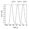
40は照明光学系である。41a〜41cはLEDを使用した照明光源で、各LEDは光の3原色であるR(赤),G(緑),B(青)の波長の光を発する。その各LEDの波長特性を図4に示す。LED41aはピーク発光波長が470nm付近にある青色波長領域の光を出射し、その青色光は光軸L上に配置されているダイクロイックミラー80、81を透過する。LED41bはピーク発光波長が560nm付近にある緑色波長領域の光を出射し、その緑色光はダイクロイックミラー80により反射されて青色光と合成された後、ダイクロイックミラー81を透過する。LED41cはピーク発光波長が650nm付近にある赤色波長領域の光を出射し、その赤色光はダイクロイックミラー81にて反射され青色光、緑色光と合成される。
【0025】
本実施の形態では、各光を同軸とするためにダイクロイックミラーを使用しているが、これに限るものではなく、ハーフミラー、偏光板、プリズム等のビームコンバイナーを使用してもよい。
【0026】
LED41a〜41cより出射し、光軸L上で同軸とされた可視光束はコンデンサレンズ42を透過した後、可変円形アパーチャ43により高さを、可変スリット板44により幅を決定され、スリット状の光束に形成される。その後、可変スリット板44を通過したスリット照明光は、投影レンズ46を介した後、分割ミラー48a、48bで反射され、コンタクトレンズ49を介して患者眼Eを照明する。47は補正レンズ、45は光路に挿脱される波長選択フィルタである。
【0027】
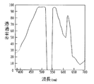
50は観察光学系である。観察光学系50は、左右の観察光路で共用される対物レンズ51と、左右の各光路に配置された変倍レンズ52、結像レンズ53、正立プリズム54、視野絞り55、接眼レンズ56、術者保護フィルタ57を備える。図5は術者保護フィルタ57の波長透過率特性を示した模式図であり、保護フィルタ57は治療レーザ光の532nmを中心とした狭帯波長域(520〜540nm)を99%以上カットし、それ以外の可視域波長の大部分を透過する特性を備えているものを使用している。
【0028】
また、保護フィルタ57は図示なきモータ等からなる移動機構により観察光路上に挿脱するようになっており、観察光路上への保護フィルタ57の挿入はフットスイッチ5のトリガ信号によって行われる。保護フィルタ57の観察光路上への挿脱状態はセンサ57aによって検知される。
【0029】
以上のような構成を備える装置において、その動作を図3の制御系を示すブロック図を用いて説明する。
【0030】
術者は点灯スイッチ7により、照明光源であるLED41a〜41cを点灯させる。このときLED41a〜41cから出射される光束の各光量は、3つの光束(赤、緑、青)が合成された後において、光の三原色であるR,G,Bの光濃度が均等になるように予め光量制御部61により調節されている。これにより、LED41a〜41cから出射した光束の合成後の光束がほぼ白色光となり、術者には自然色に近い観察視界が得られる。調節ノブ8を使用して患者眼に照射される照明光の光量を変化させる場合であっても、光量制御部61によりLED41a〜41cの光量比を変えずに光量の増減を行うため、合成後の照明光は調整ノブ8にて光量を変化させても白色光を維持することが可能である。
【0031】
このように、LEDを照明光源とするため、発熱が少なくなり熱による影響を考慮する必要もない。また、LEDは長寿命のため照明光源を頻繁に取り替えるといった手間がなくなる。
【0032】
LED41a〜41cからの光束は、ダイクロイックミラー80、81にて合成されることにより上記に記したように白色光の照明光となり、照明光学系40を経て患者眼を照明する。照明光によって照らされた眼底を、観察光学系50を通して観察する。
【0033】
次に、コントロール部2の図示なきスイッチによりエイミング光を点灯させる。エイミング光が照射されるよう設定されると、制御部60は、第2安全シャッタ18を光路上から離脱させる。
【0034】
術者は眼底に照射されるエイミング光を観察しながら、ジョイスティック6及び図示無きマニュピレータを操作して患部への位置合わせを行う。また、術者はコントロール部2の各種スイッチにより治療レーザ光の照射出力や照射時間等の照射条件を設定する。治療用レーザ照射の準備が整ったら、治療レーザ光が照射可能なREADY状態にし、図示なきマニピュレータを操作して患部へのエイミングの微調整を行う。エイミングが完了したらフットスイッチ5を踏み込みレーザ照射を行なう。制御部60はフットスイッチ5からのレーザ照射のトリガ信号を受けると、保護フィルタ57を観察光路上に挿入する。保護フィルタ57が観察光路に挿入されたことはセンサ57aによって検知され、その検知信号は光量制御部61に入力される。
【0035】
光量制御部61はセンサ57aからの検知信号を受け、保護フィルタ57の観察光路への挿入に連動してLED41a〜41cの各光量比を変化させて照明を行う。この光量比の変化量は予め決定されており、保護フィルタ57を通過するR,G,Bの光濃度が、保護フィルタ57を光路に挿入しない場合と近似するように設定される。
【0036】
すなわち、保護フィルタ57を患者眼からの反射光が通過する際、治療レーザ光をカットすべく、フィルタ57の透過特性によって520〜540nmの波長がカットされ、その緑色光の光濃度が下がる。このため、保護フィルタ57を挿入しない場合に比べ、保護フィルタ57を通した観察ではその観察像全体に色がついたように(赤みを帯びたように)観察される。そこで、保護フィルタ57でカットされた分の緑色の光濃度を補うように、保護フィルタ57を透過する緑色波長域の光濃度を相対的に増加させる。例えば、LED41bの光量を上げ、LED41cの光量を下げるというように各LEDの光量比率を変える。これにより観察像の色付きの度合いを緩和し、保護フィルタ57を光路に挿入しない場合の観察色に近似させることができる(場合によっては、青色の光量も調節する)。各41a〜41cの相対的な光量比の調整は、保護フィルタ57の有無による観察光学系での観察色ができるだけ同じになるように、実験的に定めておけば良い。
【0037】
制御部60は保護フィルタ57が観察光路上に挿入されたことをセンサ57aによって確認後、第1安全シャッタ14を光路上から離脱させ、レーザ光源10から治療レーザ光を出射させる。治療レーザ光は装置本体1の光学系、光ファイバ4及び照射光学系30に導光されて患者眼の患部に照射される。
【0038】
レーザ照射が行われ、観察光路上に保護フィルタ57が挿入されていても術者の観察は、自然色(保護フィルタ57が挿入されていない観察)に近い状態が得られているため、違和感なく患部の状態や治療結果が見易くなっている。さらに、連続してレーザ照射を行い保護フィルタ57が観察光路上に長時間挿入されている場合には、視界不良のため途中で保護フィルタ57を外し治療状態を確認するといったことがないため、特に有効である。
【0039】
また、フットスイッチ5の使用を止め、レーザ照射のトリガ信号がなくなると制御部60はレーザ光源10からのレーザ照射を止め、保護フィルタ57を観察光路から外す。保護フィルタ57の離脱を検知したセンサ57aからの信号に連動させて、同時に光量制御部61はLED41a〜41cの各光量比を保護フィルタ57挿入前の光量比に戻す。これにより、保護フィルタ57が観察光路上から外れていても最初と同じ視界が得られる。
【0040】
以上の実施形態ではLED41a〜41cの光量比の変化は、保護フィルタ57の観察光路上への挿脱を検知するセンサ57aからの信号に連動して行うものとしたが、フットスイッチ5からのレーザ照射信号に連動させて行うものとしても良い。
【0041】
また、実施形態ではRGBの波長を発する3種類のLEDを使用した例を説明したが、この3種類のLEDにて白色光が得られ難い場合には白色光が得られ易いように、さらに異なる波長域の光を発するLEDの種類を増やせば良い。照明光量が不足する場合には、各色のLEDの数を増やして導光すれば良い。
【0042】
さらにまた、本実施の形態ではレーザ治療装置を使用しているが、当然スリットランプのみでも適用できる。この場合、RGBの各LED41a〜41cを選択的に点灯したり、各LED41a〜41cの光量を個別に調整するためのスイッチ70a,70b,70cを設けておくと都合が良い(図6参照)。例えば、フルオセレインの点眼による蛍光観察ではLED41aを点灯し、フルオセレインを励起可能な青色光で患者眼を照明する。結膜等の血管観察では緑色光を発するLED41bを点灯し、赤色光の照明を排除して観察をし易くする。これにより、照明光学系に配置する波長選択のためのフィルタ機構を不要とすることも可能である。このような場合には、蛍光観察等に必要な波長を発するLEDを照明光源用のLEDとして予め用いていればよい。また、赤色光の光量を抑えたり、緑色光や青色光の光量を増加させることにより、観察部位の色に応じて観察しやすい照明光を微調整することも可能である。各LEDの点灯や光量調整は、スイッチ70a〜70cに接続された光量制御部61によって行われる。各色の光量比を変えずに全体の照明光量を調整する場合は調整ノブ8を使用する。また、蛍光観察等の種類に応じた波長を発するLEDを照明光源用のLEDと別に設けてもよい。
【0043】
さらに、RGBの3種類のLEDを使用せず、白色LEDの1種類のみの使用であっても従来のハロゲンランプやタングステンランプに比べ発熱、使用寿命の点で大いに有効である。
【0044】
【発明の効果】
以上のように、本発明によれば、LEDを使用することにより、照明光源の発熱の抑制や長寿命化が得られ、使用者の負担が減る。また、3色のLEDを使用することで、機構の簡素化が可能であり、レーザ治療では術者保護フィルタの使用時での色付きの度合いを緩和して、見易い観察が行える。
【図面の簡単な説明】
【図1】装置の外観を示す図である。
【図2】光学系を示す図である。
【図3】制御系を示すブロック図である。
【図4】LEDの波長特性を示す図である。
【図5】保護フィルタの波長吸収特性を示す図である。
【図6】各LEDを単独にて点灯させるための機構を示す図である。
【符号の説明】
1 レーザ装置本体
7 点灯スイッチ
8 調節ノブ
10 レーザ光源
30 照射光学系
40 照明光学系
41a LED
41b LED
41c LED
50 観察光学系
60 制御部
61 光量制御部
80 ダイクロイックミラー
81 ダイクロイックミラー[0001]
BACKGROUND OF THE INVENTION
The present invention relates to an ophthalmologic apparatus that performs observation or treatment by illuminating a patient's eye.
[0002]
[Prior art]
As an ophthalmologic apparatus for observing a patient's eye, a slit lamp that projects a slit-shaped illumination light on a patient's eye and performs observation through an observation optical system having a binocular microscope, the slit lamp and a laser irradiation device, There is known a laser treatment apparatus combining the above.
[0003]
These ophthalmologic devices perform observation and treatment by turning on an illumination light source installed inside the device and projecting illumination light onto a patient's eye. Generally, a tungsten lamp, a halogen lamp, or the like is used as the illumination light source. It was.
[0004]
[Problems to be solved by the invention]
However, since the illumination light source using the conventional lamp has a short life, it needs to be frequently replaced, which is troublesome for the operator. In addition, these lamps generate a large amount of heat when they are turned on, and there are cases where the surroundings may be affected by heat. Therefore, it is necessary to pay attention to the material around the illumination light source, the installation position, and the like at the time of design.
[0005]
In addition, the slit lamp is provided with a mechanism for inserting / removing a wavelength selection filter for enabling fluorescence observation into / from the illumination optical path, but this complicates the configuration of the apparatus.
[0006]
Further, in a laser treatment apparatus that performs photocoagulation or the like, a protection filter for protecting an operator's eyes from a treatment laser beam reflected from a patient's eye or the like is often attached on the optical path of the observation optical system. . However, in the observation through the protective filter that cuts the visible therapeutic laser beam, the observation image looks colored as compared with the case without the protective filter, and it is not always easy to see, such as a sense of incongruity.
[0007]
In view of the above-described drawbacks of the prior art, an object of the present invention is to provide an ophthalmic apparatus that can easily handle an illumination light source and that can simplify the configuration. Furthermore, in laser treatment, it is a technical problem to provide an ophthalmic apparatus capable of performing easy-to-see observation even when an operator protection filter is provided.
[0008]
[Means for Solving the Problems]
In order to solve the above problems, the present invention is characterized by having the following configuration.
(1) In an ophthalmologic apparatus including an observation optical system for observing a patient's eye illuminated by an illumination optical system, a plurality of LEDs that emit substantially different white light as an illumination light source of the illumination optical system and emit different wavelengths A combining unit that combines the light emitted from each LED, a light amount adjusting unit that adjusts the light amount of each LED, and a laser irradiation optical system that irradiates the patient's eye with visible treatment laser light from the treatment laser light source And an operator protection filter that cuts the treatment laser light, and is inserted into and removed from the observation optical path of the observation optical system, and the light amount adjusting means moves to the observation optical path of the operator protection filter. The light quantity ratio of each LED is changed in conjunction with the insertion / removal of the LED .
[0017]
DETAILED DESCRIPTION OF THE INVENTION
Embodiments of the present invention will be described with reference to the drawings. FIG. 1 is an external view of a laser treatment apparatus that irradiates a laser beam around an affected area of a patient's eye and performs treatment by photocoagulation.
[0018]
[0019]
FIG. 2 is a view showing an optical system of the laser photocoagulation apparatus.
[0020]
[0021]
[0022]
[0023]
The irradiation
[0024]
[0025]
In this embodiment, a dichroic mirror is used to make each light coaxial. However, the present invention is not limited to this, and a beam combiner such as a half mirror, a polarizing plate, or a prism may be used.
[0026]
The visible light beam emitted from the
[0027]
[0028]
The
[0029]
The operation of the apparatus having the above configuration will be described with reference to the block diagram showing the control system of FIG.
[0030]
The surgeon turns on the
[0031]
Thus, since LED is used as an illumination light source, heat generation is reduced and there is no need to consider the influence of heat. Moreover, since the LED has a long life, the trouble of frequently changing the illumination light source is eliminated.
[0032]
The light beams from the
[0033]
Next, the aiming light is turned on by a switch (not shown) of the
[0034]
While observing the aiming light irradiated to the fundus, the surgeon operates the
[0035]
The light
[0036]
That is, when the reflected light from the patient's eye passes through the
[0037]
The
[0038]
Even if the laser irradiation is performed and the
[0039]
Further, when the use of the
[0040]
In the above embodiment, the change in the light amount ratio of the
[0041]
Further, in the embodiment, an example in which three types of LEDs that emit RGB wavelengths are used is described. However, when it is difficult to obtain white light with these three types of LEDs, it is further different so that white light can be easily obtained. What is necessary is just to increase the kind of LED which emits the light of a wavelength range. When the amount of illumination light is insufficient, the number of LEDs of each color may be increased and guided.
[0042]
Furthermore, although the laser treatment apparatus is used in the present embodiment, it is naturally applicable only to the slit lamp. In this case, it is convenient to provide
[0043]
Furthermore, even if only one type of white LED is used without using three types of RGB LEDs, it is much more effective in terms of heat generation and service life than conventional halogen lamps and tungsten lamps.
[0044]
【The invention's effect】
As described above, according to the present invention, by using the LED, it is possible to suppress the heat generation of the illumination light source and to extend the service life, thereby reducing the burden on the user. In addition, the use of the three color LEDs can simplify the mechanism. In laser treatment, the degree of coloring during use of the operator protection filter is relaxed, and an easy-to-see observation can be performed.
[Brief description of the drawings]
FIG. 1 is a diagram showing an external appearance of an apparatus.
FIG. 2 is a diagram showing an optical system.
FIG. 3 is a block diagram showing a control system.
FIG. 4 is a diagram illustrating wavelength characteristics of an LED.
FIG. 5 is a diagram illustrating wavelength absorption characteristics of a protection filter.
FIG. 6 is a diagram showing a mechanism for lighting each LED independently.
[Explanation of symbols]
DESCRIPTION OF
41b LED
41c LED
50 Observation
Claims (1)
Priority Applications (4)
| Application Number | Priority Date | Filing Date | Title |
|---|---|---|---|
| JP2000001314A JP4469044B2 (en) | 2000-01-07 | 2000-01-07 | Ophthalmic equipment |
| US09/745,529 US6357877B2 (en) | 2000-01-07 | 2000-12-26 | Ophthalmic apparatus |
| DE60001799T DE60001799T2 (en) | 2000-01-07 | 2000-12-29 | Eye observation device with individually controlled light-emitting diodes for color-corrected lighting |
| EP00128727A EP1114608B1 (en) | 2000-01-07 | 2000-12-29 | Eye observation apparatus having a plurality of individually controlled LEDs for colour corrected illumination |
Applications Claiming Priority (1)
| Application Number | Priority Date | Filing Date | Title |
|---|---|---|---|
| JP2000001314A JP4469044B2 (en) | 2000-01-07 | 2000-01-07 | Ophthalmic equipment |
Publications (3)
| Publication Number | Publication Date |
|---|---|
| JP2001190499A JP2001190499A (en) | 2001-07-17 |
| JP2001190499A5 JP2001190499A5 (en) | 2007-02-08 |
| JP4469044B2 true JP4469044B2 (en) | 2010-05-26 |
Family
ID=18530553
Family Applications (1)
| Application Number | Title | Priority Date | Filing Date |
|---|---|---|---|
| JP2000001314A Expired - Lifetime JP4469044B2 (en) | 2000-01-07 | 2000-01-07 | Ophthalmic equipment |
Country Status (4)
| Country | Link |
|---|---|
| US (1) | US6357877B2 (en) |
| EP (1) | EP1114608B1 (en) |
| JP (1) | JP4469044B2 (en) |
| DE (1) | DE60001799T2 (en) |
Families Citing this family (39)
| Publication number | Priority date | Publication date | Assignee | Title |
|---|---|---|---|---|
| US6547394B2 (en) | 1998-10-20 | 2003-04-15 | Victor J. Doherty | Hand-held ophthalmic illuminator |
| US6361167B1 (en) * | 2000-06-13 | 2002-03-26 | Massie Research Laboratories, Inc. | Digital eye camera |
| WO2002049721A1 (en) * | 2000-12-21 | 2002-06-27 | Diverse Technologies And Systems Limited | Apparatus and method for alleviation of symptoms by application of tinted light |
| WO2002076301A1 (en) * | 2001-03-21 | 2002-10-03 | Marino Joseph A | Apparatus and method for testing visual acuity and fixation control |
| EP1462711B1 (en) * | 2001-08-23 | 2014-12-03 | Yukiyasu Okumura | Color temperature-regulable led light |
| JP3939953B2 (en) * | 2001-10-10 | 2007-07-04 | 株式会社トプコン | Laser therapy equipment |
| US7338169B2 (en) * | 2003-08-01 | 2008-03-04 | Visx, Incorporated | Slit lamp for ophthalmic use |
| US7331672B2 (en) * | 2003-08-01 | 2008-02-19 | Visx, Incorporated | Sterile hand held refractive surgery slit lamp illumination system |
| DE50310425D1 (en) * | 2003-08-05 | 2008-10-16 | Haag Ag Streit | projection perimeter |
| WO2005081914A2 (en) * | 2004-02-22 | 2005-09-09 | Doheny Eye Institute | Methods and systems for enhanced medical procedure visualization |
| SI21782A (en) * | 2004-06-04 | 2005-12-31 | Optotek D.O.O. | Slot lamp with white or colour adjustable led |
| US7273179B2 (en) * | 2004-07-09 | 2007-09-25 | Datalogic Scanning, Inc. | Portable data reading device with integrated web server for configuration and data extraction |
| US7422328B2 (en) * | 2005-05-06 | 2008-09-09 | Amo Manufacturing Usa, Llc | Sterile hand held slit lamp cover and method |
| DE102005034332A1 (en) * | 2005-07-22 | 2007-01-25 | Carl Zeiss Meditec Ag | Apparatus and method for observation, documentation and / or diagnosis of the ocular fundus |
| DE102006010105A1 (en) | 2006-02-28 | 2007-08-30 | Carl Zeiss Meditec Ag | Ophthalmologic device for observation and or documentation of eye, has homogeneous lighting, and lighting equipment consists of light source, homogenization unit and projection device |
| US7654716B1 (en) * | 2006-11-10 | 2010-02-02 | Doheny Eye Institute | Enhanced visualization illumination system |
| SE0602545L (en) | 2006-11-29 | 2008-05-30 | Tobii Technology Ab | Eye tracking illumination |
| JP2010520589A (en) * | 2007-02-28 | 2010-06-10 | ドヘニー アイ インスティテュート | Portable handheld lighting system |
| US7499624B2 (en) * | 2007-03-16 | 2009-03-03 | Alcon, Inc. | Ophthalmic Endoilluminator with Variable-Wedge Rotating-Disk Beam Attenuator |
| US7682027B2 (en) | 2007-04-09 | 2010-03-23 | Alcon, Inc. | Multi-LED ophthalmic illuminator |
| EP2178432A2 (en) * | 2007-07-04 | 2010-04-28 | i-Optics B.V. | Confocal color ophthalmoscope |
| JP5280870B2 (en) * | 2009-01-08 | 2013-09-04 | 京楽産業.株式会社 | Game machine |
| JP2013514137A (en) | 2009-12-17 | 2013-04-25 | アルコン リサーチ, リミテッド | Photonic lattice LED for eyeball illumination |
| WO2011078958A1 (en) | 2009-12-23 | 2011-06-30 | Alcon Research, Ltd. | Enhanced led illuminator |
| US9314374B2 (en) | 2010-03-19 | 2016-04-19 | Alcon Research, Ltd. | Stroboscopic ophthalmic illuminator |
| EP2568937B1 (en) | 2010-05-13 | 2018-04-11 | Doheny Eye Institute | Self contained illuminated infusion cannula system |
| US8573801B2 (en) | 2010-08-30 | 2013-11-05 | Alcon Research, Ltd. | LED illuminator |
| US9107730B2 (en) | 2010-12-09 | 2015-08-18 | Alcon Research, Ltd. | Optical coherence tomography and illumination using common light source |
| US8262224B2 (en) | 2010-12-23 | 2012-09-11 | Propper Manufacturing Co., Inc. | Binocular indirect ophthalmoscope |
| US20120203075A1 (en) | 2011-02-08 | 2012-08-09 | Christopher Horvath | White coherent laser light launched into nano fibers for surgical illumination |
| US9612656B2 (en) | 2012-11-27 | 2017-04-04 | Facebook, Inc. | Systems and methods of eye tracking control on mobile device |
| WO2014139020A1 (en) | 2013-03-15 | 2014-09-18 | Synaptive Medical (Barbados) Inc. | Surgical imaging systems |
| WO2014139018A1 (en) | 2013-03-15 | 2014-09-18 | Synaptive Medical (Barbados) Inc. | Context aware surgical systems |
| US9254079B2 (en) | 2014-01-13 | 2016-02-09 | Topcon Medical Laser Systems, Inc. | Illumination source and method for use with imaging device |
| EP3116375B1 (en) * | 2014-03-14 | 2023-07-19 | Lkc Technologies Inc. | System and method for retinopathy detection |
| US10400967B2 (en) * | 2016-06-13 | 2019-09-03 | Novartis Ag | Ophthalmic illumination system with controlled chromaticity |
| US11172560B2 (en) | 2016-08-25 | 2021-11-09 | Alcon Inc. | Ophthalmic illumination system with controlled chromaticity |
| JP2019058786A (en) * | 2019-01-24 | 2019-04-18 | 株式会社トプコン | Slit lamp microscope |
| WO2021020466A1 (en) * | 2019-07-30 | 2021-02-04 | 興和株式会社 | Fundus photographing device |
Family Cites Families (11)
| Publication number | Priority date | Publication date | Assignee | Title |
|---|---|---|---|---|
| US3760174A (en) | 1972-05-31 | 1973-09-18 | Westinghouse Electric Corp | Programmable light source |
| JPS60114233A (en) | 1983-11-24 | 1985-06-20 | 興和株式会社 | Controller in fine gap lamp microscope |
| EP0293126A1 (en) | 1987-05-20 | 1988-11-30 | Keeler Limited | Photocoagulation apparatus |
| JPH0838430A (en) | 1994-07-29 | 1996-02-13 | Canon Inc | Fundus camera |
| IL110595A0 (en) | 1994-08-09 | 1994-11-11 | Applitic Ltd | A random access multispectral video and illumination system |
| US5734459A (en) * | 1996-03-11 | 1998-03-31 | National Science Council | Anomaloscope which can generate different illuminances for test |
| JPH1033481A (en) | 1997-04-23 | 1998-02-10 | Topcon Corp | Ophthalmic lighting device |
| US5997141A (en) | 1998-03-06 | 1999-12-07 | Odyssey Optical Systems, Llc | System for treating the fundus of an eye |
| JP3807871B2 (en) | 1998-05-28 | 2006-08-09 | 株式会社ニデック | Laser therapy device |
| US6142629A (en) | 1998-08-30 | 2000-11-07 | Applied Spectral Imaging Ltd. | Spectral imaging using illumination of preselected spectral content |
| US6183086B1 (en) | 1999-03-12 | 2001-02-06 | Bausch & Lomb Surgical, Inc. | Variable multiple color LED illumination system |
-
2000
- 2000-01-07 JP JP2000001314A patent/JP4469044B2/en not_active Expired - Lifetime
- 2000-12-26 US US09/745,529 patent/US6357877B2/en not_active Expired - Lifetime
- 2000-12-29 EP EP00128727A patent/EP1114608B1/en not_active Expired - Lifetime
- 2000-12-29 DE DE60001799T patent/DE60001799T2/en not_active Expired - Fee Related
Also Published As
| Publication number | Publication date |
|---|---|
| US20010007494A1 (en) | 2001-07-12 |
| EP1114608A1 (en) | 2001-07-11 |
| JP2001190499A (en) | 2001-07-17 |
| EP1114608B1 (en) | 2003-03-26 |
| DE60001799T2 (en) | 2004-02-12 |
| DE60001799D1 (en) | 2003-04-30 |
| US6357877B2 (en) | 2002-03-19 |
Similar Documents
| Publication | Publication Date | Title |
|---|---|---|
| JP4469044B2 (en) | Ophthalmic equipment | |
| US6238385B1 (en) | Laser treatment apparatus | |
| JP3164236B2 (en) | Light therapy equipment | |
| US20020087149A1 (en) | Ophthalmic illumination device | |
| WO2016185647A1 (en) | Light source device, light source driving method, and observation device | |
| US12376739B2 (en) | Endoscopic illumination system for fluorescent agent | |
| US6530918B1 (en) | Laser treatment apparatus | |
| JP6503647B2 (en) | Laser treatment device | |
| EP0947183B1 (en) | Laser treatment apparatus | |
| JP3807871B2 (en) | Laser therapy device | |
| JP4476406B2 (en) | Stereo microscope | |
| JP2004105565A (en) | Ophthalmic photocoagulator | |
| JP3942906B2 (en) | Laser therapy device | |
| JP3892984B2 (en) | Laser photocoagulator | |
| JP2001029359A (en) | Laser surgery equipment | |
| JP3050582B2 (en) | Surgical microscope | |
| JP3199779B2 (en) | Intraocular photocoagulation device | |
| JP3939021B2 (en) | Laser therapy device | |
| JP4097569B2 (en) | Laser therapy device | |
| JP2006101940A (en) | Ophthalmological laser treatment apparatus | |
| US20080123051A1 (en) | Refractive treatment device with slit illumination | |
| JP3939953B2 (en) | Laser therapy equipment | |
| JPH09540A (en) | Fluorescent image diagnostic device for operation | |
| JPH0798050B2 (en) | Ophthalmic laser treatment device | |
| JP2000175955A (en) | Laser therapy instrument |
Legal Events
| Date | Code | Title | Description |
|---|---|---|---|
| A521 | Written amendment |
Free format text: JAPANESE INTERMEDIATE CODE: A523 Effective date: 20061215 |
|
| A621 | Written request for application examination |
Free format text: JAPANESE INTERMEDIATE CODE: A621 Effective date: 20061215 |
|
| A977 | Report on retrieval |
Free format text: JAPANESE INTERMEDIATE CODE: A971007 Effective date: 20090619 |
|
| A131 | Notification of reasons for refusal |
Free format text: JAPANESE INTERMEDIATE CODE: A131 Effective date: 20090624 |
|
| A521 | Written amendment |
Free format text: JAPANESE INTERMEDIATE CODE: A523 Effective date: 20090824 |
|
| TRDD | Decision of grant or rejection written | ||
| A01 | Written decision to grant a patent or to grant a registration (utility model) |
Free format text: JAPANESE INTERMEDIATE CODE: A01 Effective date: 20100202 |
|
| A01 | Written decision to grant a patent or to grant a registration (utility model) |
Free format text: JAPANESE INTERMEDIATE CODE: A01 |
|
| A61 | First payment of annual fees (during grant procedure) |
Free format text: JAPANESE INTERMEDIATE CODE: A61 Effective date: 20100226 |
|
| R150 | Certificate of patent or registration of utility model |
Free format text: JAPANESE INTERMEDIATE CODE: R150 |
|
| FPAY | Renewal fee payment (event date is renewal date of database) |
Free format text: PAYMENT UNTIL: 20130305 Year of fee payment: 3 |