EP2974939B1 - Train management system - Google Patents
Train management system Download PDFInfo
- Publication number
- EP2974939B1 EP2974939B1 EP14177525.4A EP14177525A EP2974939B1 EP 2974939 B1 EP2974939 B1 EP 2974939B1 EP 14177525 A EP14177525 A EP 14177525A EP 2974939 B1 EP2974939 B1 EP 2974939B1
- Authority
- EP
- European Patent Office
- Prior art keywords
- train
- timetable
- unit
- track
- signalling
- Prior art date
- Legal status (The legal status is an assumption and is not a legal conclusion. Google has not performed a legal analysis and makes no representation as to the accuracy of the status listed.)
- Active
Links
- 230000011664 signaling Effects 0.000 claims description 31
- 238000004364 calculation method Methods 0.000 claims description 14
- 238000012544 monitoring process Methods 0.000 claims description 9
- 238000007726 management method Methods 0.000 description 32
- 238000004891 communication Methods 0.000 description 23
- 238000000034 method Methods 0.000 description 16
- 230000008569 process Effects 0.000 description 15
- 238000013523 data management Methods 0.000 description 9
- 238000010586 diagram Methods 0.000 description 8
- 230000008859 change Effects 0.000 description 7
- 238000005265 energy consumption Methods 0.000 description 3
- 238000013439 planning Methods 0.000 description 3
- 230000001419 dependent effect Effects 0.000 description 2
- 238000001514 detection method Methods 0.000 description 2
- 239000000284 extract Substances 0.000 description 2
- 239000002699 waste material Substances 0.000 description 2
- 230000001133 acceleration Effects 0.000 description 1
- 239000003086 colorant Substances 0.000 description 1
- 230000001010 compromised effect Effects 0.000 description 1
- 230000007613 environmental effect Effects 0.000 description 1
- 230000003137 locomotive effect Effects 0.000 description 1
- 238000012423 maintenance Methods 0.000 description 1
- 238000012545 processing Methods 0.000 description 1
- 230000009467 reduction Effects 0.000 description 1
Images


Classifications
-
- B—PERFORMING OPERATIONS; TRANSPORTING
- B61—RAILWAYS
- B61L—GUIDING RAILWAY TRAFFIC; ENSURING THE SAFETY OF RAILWAY TRAFFIC
- B61L27/00—Central railway traffic control systems; Trackside control; Communication systems specially adapted therefor
- B61L27/10—Operations, e.g. scheduling or time tables
- B61L27/16—Trackside optimisation of vehicle or vehicle train operation
-
- B—PERFORMING OPERATIONS; TRANSPORTING
- B61—RAILWAYS
- B61L—GUIDING RAILWAY TRAFFIC; ENSURING THE SAFETY OF RAILWAY TRAFFIC
- B61L15/00—Indicators provided on the vehicle or vehicle train for signalling purposes ; On-board control or communication systems
- B61L15/0018—Communication with or on the vehicle or vehicle train
-
- B—PERFORMING OPERATIONS; TRANSPORTING
- B61—RAILWAYS
- B61L—GUIDING RAILWAY TRAFFIC; ENSURING THE SAFETY OF RAILWAY TRAFFIC
- B61L15/00—Indicators provided on the vehicle or vehicle train for signalling purposes ; On-board control or communication systems
- B61L15/0072—On-board train data handling
-
- B—PERFORMING OPERATIONS; TRANSPORTING
- B61—RAILWAYS
- B61L—GUIDING RAILWAY TRAFFIC; ENSURING THE SAFETY OF RAILWAY TRAFFIC
- B61L21/00—Station blocking between signal boxes in one yard
- B61L21/06—Vehicle-on-line indication; Monitoring locking and release of the route
- B61L21/065—Vehicle-on-line indication; Monitoring locking and release of the route for signals, including signals actuated by the vehicle
-
- B—PERFORMING OPERATIONS; TRANSPORTING
- B61—RAILWAYS
- B61L—GUIDING RAILWAY TRAFFIC; ENSURING THE SAFETY OF RAILWAY TRAFFIC
- B61L23/00—Control, warning, or like safety means along the route or between vehicles or vehicle trains
- B61L23/34—Control, warnings or like safety means indicating the distance between vehicles or vehicle trains by the transmission of signals therebetween
Definitions
- the present invention relates to a train management system, and in particular, but not exclusively, to such a system that makes use of a driver advisory system of a railway vehicle.
- a Driver Advisory System can calculate an optimized driving speed profile for a given train based on the train location, track information, the train route and the train timetable.
- the DAS can then present driving advice to the train driver based on the calculation.
- Such systems are becoming increasingly important for environmental and cost-saving reasons because of the potential, if a driver follows the advice, for improvements in safety and punctuality, and reductions in energy consumption and brake maintenance costs.
- WO 98/30426 proposes a method for controlling the speed of a rail vehicle.
- the present invention provides a train management system according to claim 1.
- the driver can be presented with real-time speed profile advice that not only takes into account the latest signal settings, but also takes into account the latest timetable for the train.
- inconsistencies between the advice and the signals can be reduced or eliminated, improving train safety.
- the train can be driven at a speed which is optimised in terms of ride comfort, reduced mechanical wear and tear, and overall network utilisation.
- the calculation module can be a part of the on-board server unit.
- the railway operating centre may further include an interface unit which, while the given train is running, sends the latest updated timetable and the latest updated signals to the on-board server unit.
- the interface unit may further include a signalling management module which checks if the signalling settings in front of the given train have changed, the interface unit sending the updated signals to the on-board server unit only when the signalling settings in front of the train have changed.
- the railway operating centre further include an interface unit, and for the calculation module to be a part of that interface unit, which sends the recommended speed profile to the on-board server unit.
- the interface unit can also send the latest updated timetable and the latest updated signals to the on-board server unit.
- the on-board server unit may also display the latest updated timetable and the latest updated signals as advice for the driver of the train.
- the railway operating centre may further include a track description database which contains information on maximum track speeds.
- the calculation module can then calculate the recommended speed profile for the given train compatible with the latest updated timetable and the latest updated signals but not exceeding the maximum speeds.
- the interface unit can send the information on maximum speeds to the on-board server unit.
- the track description database typically also contains information on track gradients and curves. The recommended speed profile can be calculated to be compatible with this information as well.
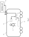
- Figure 1 shows an operational background of the invention.
- Figure 1 shows trackside equipment (208), an interface unit (101), a train (102), a communication antenna (103), and an on-board server unit (104) which includes a driver-machine interface (106) (i.e. a display).
- a driver-machine interface (106) i.e. a display
- the trackside equipment (208) typically include, for example, signals, points, train detection equipment, and train protection equipment. Based on timetables and the train locations detected by the train detection equipment, signalling settings to be enacted by the signals of the trackside equipment are decided.
- a railway operating centre (105) collects the signalling settings and the running statuses of all the trains in a pre-defined geographical region, which can contain one or multiple railway routes.
- the interface unit (101) provides a communications link using the communication antenna (103) between the on-board server unit (104) and a railway Traffic Management System (TMS) in the rail operating centre (105).
- TMS Traffic Management System
- the on-board server unit (104) has a calculation module which processes data obtained from the interface unit (101) and optionally also processes data obtained from other train-borne devices.
- the on-board server unit (104) calculates driving advice for the train driver according to the obtained data, and displays the advice on the driver-machine interface (106).
- the calculation of the driving advice is performed by a calculation module of the interface unit (101), which then sends the advice for display by the driver-machine interface (106) of the on-board server unit (104).
- the present invention enables the creation and display of such driving advice while the train is being run. In this way, the advice available to the driver can be continuously refreshed.
- the interface unit (101) can receive information from the on-board server unit (104) so that the TMS is informed of train statuses. This information can be used to improve management decisions by the TMS.
- Figure 2 illustrates the system architecture inside the railway operating centre (105).
- the railway operating centre (105) includes a timetable planning unit (209), a track description database (206) and the TMS (201).
- a track monitoring unit (207) within the TMS has two main functions. Firstly it automatically monitors real-time train locations and statuses of trackside equipment (208) by monitoring an interlocking unit (not shown) that controls the trackside equipment (208). Secondly the track monitoring unit sets routes for each train and creates signalling settings for the signals to avoid route conflicts based on the real-time train locations and trackside equipment statuses. The track monitoring unit sends the train routes and signalling settings to the interlocking unit.
- a timetable updating unit (202) within the TMS (201) updates the train running timetable, which is originally prepared by the timetable planning unit (209).
- the train running timetable created by the timetable planning unit (209) includes departure and arrival times of trains from timing points, including train stations. Under undisrupted running situations, trains run according to the planned timetable. Under disruption, the timetable updating unit (202) predicts feasible arrival and departure times and automatically creates an updated timetable.
- the timetable updating unit (202) can include a human interface having a display unit and an input unit. A human operator can then view the updated timetable on the display unit, and can adjust the timetable via the input unit if necessary. In this way, a finally updated timetable is created in the timetable updating unit (202).
- Track description database (206) stores and manages data about the railway lines.
- the track description database may be located in the railway operating centre (105).
- the railway line data can include starting and ending points of track sections, lengths of track sections, connectivities of track sections, locations of points, locations of timing points, locations of signal lights, maximum line speeds of track sections, temporary speed restrictions, track gradients, starting and ending points of track gradients, track curves, starting and ending points of track curves.
- the timetable updating unit (202) receives track description data from the track description database (206), and uses the data for creating the updated timetable.
- the interface unit (101) receives the updated timetable from the timetable updating unit (202) and signal updates from the track monitoring unit (207).
- the interface unit (101) can also receive track description data from the track description database server (206).
- the interface unit (101) can connect to the train through GSM-R, the international wireless communications standard for railway operations.
- FIG 3 shows on-board components of a driver advisory system (DAS).
- a Driver Machine Interface (DMI) (106) is placed inside the driver's cab. It provides the driver (110) with advice about optimal driving speeds and other relevant information.
- the DMI can also display upcoming real-time signaling settings received via the train interface unit (101), updated timetables, track speed limits, track gradients, other trains' locations, etc. in order to provide the driver with assistive information.
- the on-board server unit (104) receives input from the interface unit (101).
- the on-board server unit (104) also receives input such as instantaneous train speed and GPS location from other on-board equipment (107).
- the on-board server unit (104) calculates a recommended speed and a recommended speed profile (303).
- the interface unit (101) calculates a recommended speed and a recommended speed profile which are sent to the on-board server unit (104). Either way, the calculation results are displayed by the DMI (106).
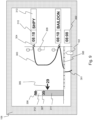
- Figure 9 illustrates an example of display contents shown by the DMI.
- the rectangular bar on the left is a speed indicator.
- the line speed limit is represented by the height of a white bar (312).
- the exact value of the speed limit (306) is displayed at the top of the white bar.
- the displayed line speed limit is dynamic, depending on the section of track the train is travelling on.
- the speed limit (306) can be sent from the track description database (206) via the interface unit (101).
- the current speed (311) is represented by the height of a shaded bar (311) overlayed on the white bar (312). The exact value of the current speed (307) can be displayed at the top of the shaded bar.
- the current speed (311) can be sent from the on-board equipment (107).
- the recommended speed (305) is indicated by an arrow, and the exact value of the recommended speed is displayed by the side of the arrow.
- a horizontal current location line (308) indicates the current location of the train (102) against a vertical journey line indicating upcoming track sections.
- the markers on the horizontal line are speed markers.
- the recorded speed profile (301) is indicated by a bold line below the current location line (308).
- the recommended speed profile (303) is indicated by a bold line above the current location line.
- the recorded speed profile is dependent historical record of the actual speed of the train.
- the recommended speed profile is calculated by the on-board server unit (104) or the interface unit (101), depending on the updated timetable, the track description data, the signal updates, and optionally train conditions.
- Timing point locations (304) are indicated by small triangles on the vertical line indicating upcoming track sections.
- the name (313) and scheduled time (310) for each TIPLOC is displayed next to the TIPLOC symbol. Names of the TIPLOCs can be extracted from the updated timetable. Although often abbreviated, TIPLOC names are familiar to qualified drivers.
- the current time (302) is displayed to the right of the current location line (308).
- Indicators (309) for upcoming signalling lights are displayed along the vertical journey line at appropriate positions.
- the updated signals can be displayed on the signal indicators in the display.
- real-time signal changes can be reflected in real-time changes on the DMI display.
- Driving advice such as new recommended speed profiles, new recommended speeds and updated signals, are re-calculated by the on-board server unit (104) or the the interface unit (101) when the timetable is updated and/or any signalling settings change.
- FIG. 4 illustrates the architecture of functional modules of the interface unit (101).
- a communication and control module (113) handles all internal communications between functional modules, and all external communications with other units.
- the main incoming data from the railway operating centre (105) are track descriptions from the track description database server (206), planned and updated timetables (211) from the timetable updating unit (202), and an interlocking data file (212) from the track monitoring unit (207).
- a signal management module (114) receives and processes the real-time signalling settings (212). Updated signals are extracted from the signalling settings and sent to relevant trains.
- a timetable management module (115) receives and processes the updated timetable (211). Relevant timetables are extracted from all the updated timetables and send to relevant trains.
- a train register module (116) keeps a list of train IDs of those trains in the TMS controlled area.
- a track data management module (117) manages track data of the controlled area. For example, the module can keep a copy of the track data. When any track data are changed, the update is sent to the module (117) from the track description database (206).
- a train running management module (118) keeps train running statuses, including latest received locations, speeds and predicted arrival times.
- a time synchronisation module (119) adjusts the system time when the interface unit application is started.
- a communication and control module (113) manages incoming and outgoing messages with the trains that are in the control area. It also manages internal communications between the above-mentioned functional modules (114-119).
- FIG. 5 shows the working arrangement of the signal management module (114).
- the track monitoring unit (207) in the TMS sends the interlocking data file (212) to the communication and control module (113), which sends it to the signal management module (114).
- the signal management module (114) then returns an acknowledgement to the track monitoring unit (207).
- a comparison function (121) within the the signal management module compares the incoming interlocking data with the last received interlocking data. If there is no change, the signal management module waits for another regular interlocking data update.
- the signal management module (114) calls the train register module (116) to obtain a copy of the list of trains that are currently in the control area.
- the signal management module (114) then loops over each train in the control area to check if the signals in front of this train have changed using a comparing function (123). If the signals have changed for the train being considered, relevant signal updates are prepared by the output function (122) to be sent to the train via the communication and control module (113). The same process continues to other trains in the current list until all the trains in the control area have been tested.
- the signal management module waits for another interlocking data update.
- Figure 6 shows how the comparing function (123) identifies whether the signals in front of a given train have changed.
- the function first calls train running module (118), which returns the GPS location of the train to the function.
- the function then calls the track management module (117) with the GPS location as argument.
- the track management module returns the signal IDs in front of the given location.
- the comparing function then compares the signals' settings.
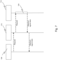
- Figure 7 shows a sequence diagram illustrating a signal update process.
- the on-board server unit (104) may request signal updates from the interface unit (101).
- the module (113) forwards the request to the signal management module (114).
- the signal management module search function (124) searches for the requested signal and returns the relevant data to the on-board server unit (104) via the communication and control module (113).
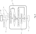
- FIG 8 shows the working arrangement of the timetable management module (115).
- the timetable updating unit (202) in the TMS prepares and sends updated timetables (211) to the communication and control module (113), which send them to the timetable management module (115).
- the timetable management module (115) then returns an acknowledgement to the timetable updating unit (202).
- An updated timetable (211) does not have to be a full timetable. It may only relate to trains whose timetables are changed.
- the timetable management module (115) loops over each train that is specified in the updated timetable.
- the timetable processing function (131) prepares data for each affected train. The data is output to the communication and control module (113), which sends it to corresponding trains.
- the updated timetable and the updated signals are displayed by the DMI, and are also used to calculate a recommended speed profile which is displayed by the DMI.
- the signal indicators (309) shown by the DMI can show not only the upcoming signal positions but also updated signal settings.
- a vertical line on a given signal can indicate a green signal, a tilted line an amber signal and ahorizontal line a red signal.
- the updated signal colours can be indicated directly by the colour of the signal indicator circle.
- the recommended speed profile (303) can be calculated by a module of the on-board server unit (104), depending on the updated timetable, the track description data, the signalling updates and optionally locomotive conditions.
- the on-board server unit (104) extracts the scheduled time of each TIPLOC (SHPY and BAILDON) from the updated timetable.
- the on-board server unit (104) also extracts the line speed limit (312) from the track description database, and the updated signalling setting of each signal indicator in front of the train.
- the recommended speed profile (303) is calculated so that the train arrives at each TIPLOC on time, the train speed does not exceed the line speed limit (312), and the signals are obeyed.
- the recommended speed profile (303) can be calculated so that the train can avoid unnecessary acceleration and braking, thereby improving ride comfort and reducing energy consumption.
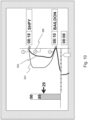
- Figure 10 illustrates the display contents shown by the DMI when the signal settings change without a timetable change.
- the setting changes are reflected by the signal indicators (309), and the recommended speed profile (303) is adjusted to reflect the changed signal settings.
- the middle signal indicator (309) shows amber, changed from green, and the upper signal indicator shows red, changed from green.
- the recommended speed profile (303) is adjusted to a slower speed profile, because the amber signal could change to red. Without this updated signalling information, the DMI would continue to display the original recommended speed profile (323). Then, if a driver drove according to the original recommended speed profile (323) and did not observe the amber signal, a safety system may have to be actuated to force a stop to avoid running through a red signal. This is undesirable, not only from a compromised safety viewpoint, but also because it reduces ride comfort, wastes energy and increases brake wear and tear.
- Figure 11 illustrates the display contents shown by the DMI when the upper and middle signal indicators (309) display red signals, changed from green, and the lower signal indicator shows amber, changed from green.
- the recommended speed profile (303) is now adjusted to even slower speeds and advises a stop at the middle signal. Again, without the updated signalling information, the DMI would mislead the driver.
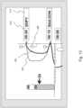
- Figure 12 illustrates the display contents shown by the DMI when there is a timetable update.
- the DMI displays the updated timetable using the scheduled time indicator (310), and the on-board server unit (104) recalculates and adjusts the recommended speed profile (303) which is also displayed on the DMI.
- the updated timetable changes the scheduled time (310) of TIPLOC SHPY (304), from 08:18 to 08:26.
- the recommended speed profile (303) is changed to a slower speed compatible with the later scheduled time, and thereby reduces energy consumption.
- the train stops at TIPLOC SHPY for a relatively short time. This reduced stop time increases the possibilities for other train to maneouver using the available track and recover faster from disruption, hence the overall reliability of the railway network can be improved.
- the DMI would still display the original timetable and the original speed profile (323) based on the original timetable. If the driver drove according to the original advice, the train would accelerate to a higher speed compatible with the original timetable (08:18). The train would then stop at SHPY until the updated timetable time (08:26) was reached. Therefore, the train would reach to SHPY too early and waste energy.
- the DMI shows the same display as described above in relation to Figures 9 to 12 .
- this calculation can be performed for each train by a further module of the interface unit (101).
- the recommended speed profile can then be transmitted to each train, along with the relevant updated timetable, updated signals and track description data, via the communication and control module (113).
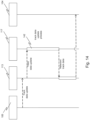
- Figure 13 is a sequence diagram showing an initialisation process of the track data.
- the communication and control module (113) sends a request to the railway operating centre (105).
- the railway operating centre (105) sends the full track data from the track description database (206) to the communication and control module (113), which forwards the data to the track data management module (117).
- the track data management module (117) processes the track data and prepares for each train in the control area the relevant track data.
- the relevant data is forwarded to the individual on-board server unit (104) via the communication and control module (113).
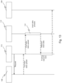
- Figure 14 is a sequence diagram showing an update process of the track data.
- update process of the track data When there is any update of the track data, especially temporary speed restrictions or emergency speed restrictions, such updates are sent to the track data management module (117) via the communication and control module (113).
- the track data management module (117) processes the updated track data and prepares for each train in the control area affected by the track data update the relevant track data.
- the relevant data is forwarded to the individual on-board server unit (104) via the communication and control module (113).
- the track data management module (117) stores the links between GPS coordinates and positions on track sections. If GPS coordinates are input to the module (117), the module returns the upcoming signals and track data.
- Figure 15 is a sequence diagram showing the process of searching for train-related signals.
- the track data management module (117) searches the relevant track section and returns to the signalling management module the relevant track data, including signal and upcoming track details.
- a more integrated option is for the track data management module (117) to make a query to the track description database (206) when necessary, but not to store track data itself.
- the train register module (116) maintains a list of train IDs of those trains in the TMS controlled area.
- the train register module (116) can store a copy of the train list from the TMS.
- Another option is for the train register module (116) to monitor the boundary of the controlled area. The module can then add a train ID to the list when a train arrives at the boundary, and remove a train ID from the list when a train leaves the controlled area form the boundary.
- the train register module can maintain a record of the on-board server unit (104) connection details for each currently registered trains.
- the on-board server unit (104) can send the current location of the train to the interface unit (101).
- the communication and control module (113) forwards such data to the train running module (118).
- the signalling management module (114) checks whether the signal settings are changed for the train in question, it first calls the train running management module (118) to get the location of the train. When contacted, the train running management module (118) returns the GPS location of train to the signalling management module.
- the on-board server unit (104) or the interface unit (101) can predict the running time of train, based on the recommended speed profile. The predicted running time may be sent to the train running module (118). The module can then forward such information to the TMS.
- the on-board server unit (104) or the interface unit (101) can send to the train running module (118) a message to indicate whether the timetable can be achieved by the train.
- the train running module can also forward such information to the TMS.
Description
- The present invention relates to a train management system, and in particular, but not exclusively, to such a system that makes use of a driver advisory system of a railway vehicle.
- A Driver Advisory System (DAS) can calculate an optimized driving speed profile for a given train based on the train location, track information, the train route and the train timetable.
- The DAS can then present driving advice to the train driver based on the calculation. Such systems are becoming increasingly important for environmental and cost-saving reasons because of the potential, if a driver follows the advice, for improvements in safety and punctuality, and reductions in energy consumption and brake maintenance costs.
-
WO 98/30426 - A problem can arise when advice given by a DAS is inconsistent with signal settings in front of the train. In this situation, the driver should drive the train based on the signal settings, but the incorrect advice may distract or disturb the driver. Thus for safety, the advice given by the DAS should be consistent with signalling. In addition, incorrect or sub-optimal advice can reduce or eliminate energy efficiency improvements e.g. due to sudden braking when advice is inconsistent with signal settings. It would also be desirable to improve ride comfort and reduce brake wear.
- Accordingly, the present invention provides a train management system according to claim 1.
- Thus, advantageously, the driver can be presented with real-time speed profile advice that not only takes into account the latest signal settings, but also takes into account the latest timetable for the train. In this way, inconsistencies between the advice and the signals can be reduced or eliminated, improving train safety. However, in addition, the train can be driven at a speed which is optimised in terms of ride comfort, reduced mechanical wear and tear, and overall network utilisation.
- Optional features of the invention will now be set out. These are applicable as defined by the appended dependent claims.
- The calculation module can be a part of the on-board server unit. In this case, the railway operating centre may further include an interface unit which, while the given train is running, sends the latest updated timetable and the latest updated signals to the on-board server unit. The interface unit may further include a signalling management module which checks if the signalling settings in front of the given train have changed, the interface unit sending the updated signals to the on-board server unit only when the signalling settings in front of the train have changed.
- Another option, however, is for the railway operating centre to further include an interface unit, and for the calculation module to be a part of that interface unit, which sends the recommended speed profile to the on-board server unit. In this case, the interface unit can also send the latest updated timetable and the latest updated signals to the on-board server unit.
- The on-board server unit may also display the latest updated timetable and the latest updated signals as advice for the driver of the train.
- The railway operating centre may further include a track description database which contains information on maximum track speeds. The calculation module can then calculate the recommended speed profile for the given train compatible with the latest updated timetable and the latest updated signals but not exceeding the maximum speeds. When the calculation module is a part of the on-board server unit, the interface unit can send the information on maximum speeds to the on-board server unit. The track description database typically also contains information on track gradients and curves. The recommended speed profile can be calculated to be compatible with this information as well.
- Embodiments of the invention will now be described by way of example with reference to the accompanying drawings in which:
-
Figure 1 shows an operational background of the invention; -
Figure 2 shows system architecture inside a railway operating centre; -
Figure 3 shows on-board components of a DAS; -
Figure 4 shows functional modules of an interface unit; -
Figure 5 shows a flow chart of a signal management module; -
Figure 6 shows a flow chart of comparing function; -
Figure 7 shows a sequence diagram illustrating a signal update process; -
Figure 8 shows a flow chart of a timetable management module; -
Figure 9 shows an example of a Driver Machine Interface (DMI) display; -
Figure 10 shows the DMI display with signalling light changes; -
Figure 11 shows the DMI display with further signalling light changes; -
Figure 12 shows of the DMI display with a the timetable change; -
Figure 13 shows a sequence diagram illustrating an initialisation process of track data; -
Figure 14 shows a sequence diagram illustrating an update process of the track data; and -
Figure 15 shows a sequence diagram illustrating a process of searching for train-related signals; -
Figure 1 shows an operational background of the invention. In particular,Figure 1 shows trackside equipment (208), an interface unit (101), a train (102), a communication antenna (103), and an on-board server unit (104) which includes a driver-machine interface (106) (i.e. a display). - The trackside equipment (208) typically include, for example, signals, points, train detection equipment, and train protection equipment. Based on timetables and the train locations detected by the train detection equipment, signalling settings to be enacted by the signals of the trackside equipment are decided.
- A railway operating centre (105) collects the signalling settings and the running statuses of all the trains in a pre-defined geographical region, which can contain one or multiple railway routes.
- The interface unit (101) provides a communications link using the communication antenna (103) between the on-board server unit (104) and a railway Traffic Management System (TMS) in the rail operating centre (105).
- According to a first embodiment, the on-board server unit (104) has a calculation module which processes data obtained from the interface unit (101) and optionally also processes data obtained from other train-borne devices. In particular, the on-board server unit (104) calculates driving advice for the train driver according to the obtained data, and displays the advice on the driver-machine interface (106). According to a second embodiment, the calculation of the driving advice is performed by a calculation module of the interface unit (101), which then sends the advice for display by the driver-machine interface (106) of the on-board server unit (104).
- The present invention enables the creation and display of such driving advice while the train is being run. In this way, the advice available to the driver can be continuously refreshed.
- Optionally, the interface unit (101) can receive information from the on-board server unit (104) so that the TMS is informed of train statuses. This information can be used to improve management decisions by the TMS.
-
Figure 2 illustrates the system architecture inside the railway operating centre (105). In particular, the railway operating centre (105) includes a timetable planning unit (209), a track description database (206) and the TMS (201). - A track monitoring unit (207) within the TMS has two main functions. Firstly it automatically monitors real-time train locations and statuses of trackside equipment (208) by monitoring an interlocking unit (not shown) that controls the trackside equipment (208). Secondly the track monitoring unit sets routes for each train and creates signalling settings for the signals to avoid route conflicts based on the real-time train locations and trackside equipment statuses. The track monitoring unit sends the train routes and signalling settings to the interlocking unit.
- A timetable updating unit (202) within the TMS (201) updates the train running timetable, which is originally prepared by the timetable planning unit (209). The train running timetable created by the timetable planning unit (209) includes departure and arrival times of trains from timing points, including train stations. Under undisrupted running situations, trains run according to the planned timetable. Under disruption, the timetable updating unit (202) predicts feasible arrival and departure times and automatically creates an updated timetable. The timetable updating unit (202) can include a human interface having a display unit and an input unit. A human operator can then view the updated timetable on the display unit, and can adjust the timetable via the input unit if necessary. In this way, a finally updated timetable is created in the timetable updating unit (202).
- Track description database (206) stores and manages data about the railway lines. the track description database may be located in the railway operating centre (105). The railway line data can include starting and ending points of track sections, lengths of track sections, connectivities of track sections, locations of points, locations of timing points, locations of signal lights, maximum line speeds of track sections, temporary speed restrictions, track gradients, starting and ending points of track gradients, track curves, starting and ending points of track curves.
- The timetable updating unit (202) receives track description data from the track description database (206), and uses the data for creating the updated timetable.
- The interface unit (101) receives the updated timetable from the timetable updating unit (202) and signal updates from the track monitoring unit (207). The interface unit (101) can also receive track description data from the track description database server (206).
- The interface unit (101) can connect to the train through GSM-R, the international wireless communications standard for railway operations.
-
Figure 3 shows on-board components of a driver advisory system (DAS). A Driver Machine Interface (DMI) (106) is placed inside the driver's cab. It provides the driver (110) with advice about optimal driving speeds and other relevant information. The DMI can also display upcoming real-time signaling settings received via the train interface unit (101), updated timetables, track speed limits, track gradients, other trains' locations, etc. in order to provide the driver with assistive information. - The on-board server unit (104) receives input from the interface unit (101). The on-board server unit (104) also receives input such as instantaneous train speed and GPS location from other on-board equipment (107). According to the first embodiment, the on-board server unit (104) calculates a recommended speed and a recommended speed profile (303). According to the second embodiment, the interface unit (101) calculates a recommended speed and a recommended speed profile which are sent to the on-board server unit (104). Either way, the calculation results are displayed by the DMI (106).
-
Figure 9 illustrates an example of display contents shown by the DMI. The rectangular bar on the left is a speed indicator. The line speed limit is represented by the height of a white bar (312). The exact value of the speed limit (306) is displayed at the top of the white bar. The displayed line speed limit is dynamic, depending on the section of track the train is travelling on. The speed limit (306) can be sent from the track description database (206) via the interface unit (101). - The current speed (311) is represented by the height of a shaded bar (311) overlayed on the white bar (312). The exact value of the current speed (307) can be displayed at the top of the shaded bar. The current speed (311) can be sent from the on-board equipment (107).
- The recommended speed (305) is indicated by an arrow, and the exact value of the recommended speed is displayed by the side of the arrow.
- A horizontal current location line (308) indicates the current location of the train (102) against a vertical journey line indicating upcoming track sections. The markers on the horizontal line are speed markers. The recorded speed profile (301) is indicated by a bold line below the current location line (308). The recommended speed profile (303) is indicated by a bold line above the current location line. The recorded speed profile is dependent historical record of the actual speed of the train. The recommended speed profile is calculated by the on-board server unit (104) or the interface unit (101), depending on the updated timetable, the track description data, the signal updates, and optionally train conditions.
- Timing point locations (TIPLOC) (304) are indicated by small triangles on the vertical line indicating upcoming track sections. The name (313) and scheduled time (310) for each TIPLOC is displayed next to the TIPLOC symbol. Names of the TIPLOCs can be extracted from the updated timetable. Although often abbreviated, TIPLOC names are familiar to qualified drivers.
- The current time (302) is displayed to the right of the current location line (308).
- Indicators (309) for upcoming signalling lights are displayed along the vertical journey line at appropriate positions. The updated signals can be displayed on the signal indicators in the display. In this way, real-time signal changes can be reflected in real-time changes on the DMI display. Driving advice, such as new recommended speed profiles, new recommended speeds and updated signals, are re-calculated by the on-board server unit (104) or the the interface unit (101) when the timetable is updated and/or any signalling settings change.
-
Figure 4 illustrates the architecture of functional modules of the interface unit (101). - A communication and control module (113) handles all internal communications between functional modules, and all external communications with other units.
- The main incoming data from the railway operating centre (105) are track descriptions from the track description database server (206), planned and updated timetables (211) from the timetable updating unit (202), and an interlocking data file (212) from the track monitoring unit (207).
- A signal management module (114) receives and processes the real-time signalling settings (212). Updated signals are extracted from the signalling settings and sent to relevant trains.
- A timetable management module (115) receives and processes the updated timetable (211). Relevant timetables are extracted from all the updated timetables and send to relevant trains.
- A train register module (116) keeps a list of train IDs of those trains in the TMS controlled area.
- A track data management module (117) manages track data of the controlled area. For example, the module can keep a copy of the track data. When any track data are changed, the update is sent to the module (117) from the track description database (206).
- A train running management module (118) keeps train running statuses, including latest received locations, speeds and predicted arrival times.
- A time synchronisation module (119) adjusts the system time when the interface unit application is started.
- A communication and control module (113) manages incoming and outgoing messages with the trains that are in the control area. It also manages internal communications between the above-mentioned functional modules (114-119).
-
Figure 5 shows the working arrangement of the signal management module (114). The track monitoring unit (207) in the TMS sends the interlocking data file (212) to the communication and control module (113), which sends it to the signal management module (114). The signal management module (114) then returns an acknowledgement to the track monitoring unit (207). Upon receiving the interlocking data, a comparison function (121) within the the signal management module compares the incoming interlocking data with the last received interlocking data. If there is no change, the signal management module waits for another regular interlocking data update. - If there is change with the interlocking data, the signal management module (114) calls the train register module (116) to obtain a copy of the list of trains that are currently in the control area. The signal management module (114) then loops over each train in the control area to check if the signals in front of this train have changed using a comparing function (123). If the signals have changed for the train being considered, relevant signal updates are prepared by the output function (122) to be sent to the train via the communication and control module (113). The same process continues to other trains in the current list until all the trains in the control area have been tested.
- After each train is tested, the signal management module waits for another interlocking data update.
-
Figure 6 shows how the comparing function (123) identifies whether the signals in front of a given train have changed. The function first calls train running module (118), which returns the GPS location of the train to the function. The function then calls the track management module (117) with the GPS location as argument. The track management module returns the signal IDs in front of the given location. The comparing function then compares the signals' settings. -
Figure 7 shows a sequence diagram illustrating a signal update process. When the train drives along the track, the on-board server unit (104) may request signal updates from the interface unit (101). When such a request is received by the communication and control module (113), the module (113) forwards the request to the signal management module (114). The signal management module search function (124) searches for the requested signal and returns the relevant data to the on-board server unit (104) via the communication and control module (113). -
Figure 8 shows the working arrangement of the timetable management module (115). The timetable updating unit (202) in the TMS prepares and sends updated timetables (211) to the communication and control module (113), which send them to the timetable management module (115). The timetable management module (115) then returns an acknowledgement to the timetable updating unit (202). An updated timetable (211) does not have to be a full timetable. It may only relate to trains whose timetables are changed. Upon receiving the timetable data, the timetable management module (115) loops over each train that is specified in the updated timetable. The timetable processing function (131) prepares data for each affected train. The data is output to the communication and control module (113), which sends it to corresponding trains. - The updated timetable and the updated signals are displayed by the DMI, and are also used to calculate a recommended speed profile which is displayed by the DMI.
- Thus, as mentioned previously, in
Figure 9 the signal indicators (309) shown by the DMI can show not only the upcoming signal positions but also updated signal settings. For example, a vertical line on a given signal can indicate a green signal, a tilted line an amber signal and ahorizontal line a red signal. If the DMI has colour display, the updated signal colours can be indicated directly by the colour of the signal indicator circle. - As also mentioned previously, according to a first embodiment, the recommended speed profile (303) can be calculated by a module of the on-board server unit (104), depending on the updated timetable, the track description data, the signalling updates and optionally locomotive conditions. For example, the on-board server unit (104) extracts the scheduled time of each TIPLOC (SHPY and BAILDON) from the updated timetable. The on-board server unit (104) also extracts the line speed limit (312) from the track description database, and the updated signalling setting of each signal indicator in front of the train. Based on this information, the recommended speed profile (303) is calculated so that the train arrives at each TIPLOC on time, the train speed does not exceed the line speed limit (312), and the signals are obeyed. Optionally, the recommended speed profile (303) can be calculated so that the train can avoid unnecessary acceleration and braking, thereby improving ride comfort and reducing energy consumption.
-
Figure 10 illustrates the display contents shown by the DMI when the signal settings change without a timetable change. The setting changes are reflected by the signal indicators (309), and the recommended speed profile (303) is adjusted to reflect the changed signal settings. - More particularly, the middle signal indicator (309) shows amber, changed from green, and the upper signal indicator shows red, changed from green. The recommended speed profile (303) is adjusted to a slower speed profile, because the amber signal could change to red. Without this updated signalling information, the DMI would continue to display the original recommended speed profile (323). Then, if a driver drove according to the original recommended speed profile (323) and did not observe the amber signal, a safety system may have to be actuated to force a stop to avoid running through a red signal. This is undesirable, not only from a compromised safety viewpoint, but also because it reduces ride comfort, wastes energy and increases brake wear and tear.
-
Figure 11 illustrates the display contents shown by the DMI when the upper and middle signal indicators (309) display red signals, changed from green, and the lower signal indicator shows amber, changed from green. The recommended speed profile (303) is now adjusted to even slower speeds and advises a stop at the middle signal. Again, without the updated signalling information, the DMI would mislead the driver. -
Figure 12 illustrates the display contents shown by the DMI when there is a timetable update. The DMI displays the updated timetable using the scheduled time indicator (310), and the on-board server unit (104) recalculates and adjusts the recommended speed profile (303) which is also displayed on the DMI. In this case, the updated timetable changes the scheduled time (310) of TIPLOC SHPY (304), from 08:18 to 08:26. Accordingly, the recommended speed profile (303) is changed to a slower speed compatible with the later scheduled time, and thereby reduces energy consumption. Additionally, because the train is slower, it stops at TIPLOC SHPY for a relatively short time. This reduced stop time increases the possibilities for other train to maneouver using the available track and recover faster from disruption, hence the overall reliability of the railway network can be improved. - Without the updated timetable, the DMI would still display the original timetable and the original speed profile (323) based on the original timetable. If the driver drove according to the original advice, the train would accelerate to a higher speed compatible with the original timetable (08:18). The train would then stop at SHPY until the updated timetable time (08:26) was reached. Therefore, the train would reach to SHPY too early and waste energy.
- In the second embodiment, the DMI shows the same display as described above in relation to
Figures 9 to 12 . However, instead of the on-board server unit (104) calculating the recommended speed profile, this calculation can be performed for each train by a further module of the interface unit (101). The recommended speed profile can then be transmitted to each train, along with the relevant updated timetable, updated signals and track description data, via the communication and control module (113). -
Figure 13 is a sequence diagram showing an initialisation process of the track data. When the DAS interface system starts up, the communication and control module (113) sends a request to the railway operating centre (105). Upon receiving the request, the railway operating centre (105) sends the full track data from the track description database (206) to the communication and control module (113), which forwards the data to the track data management module (117). The track data management module (117) processes the track data and prepares for each train in the control area the relevant track data. The relevant data is forwarded to the individual on-board server unit (104) via the communication and control module (113). -
Figure 14 is a sequence diagram showing an update process of the track data. When there is any update of the track data, especially temporary speed restrictions or emergency speed restrictions, such updates are sent to the track data management module (117) via the communication and control module (113). The track data management module (117) processes the updated track data and prepares for each train in the control area affected by the track data update the relevant track data. The relevant data is forwarded to the individual on-board server unit (104) via the communication and control module (113). - The track data management module (117) stores the links between GPS coordinates and positions on track sections. If GPS coordinates are input to the module (117), the module returns the upcoming signals and track data.
Figure 15 is a sequence diagram showing the process of searching for train-related signals. When the signalling management module (114) sends the train GPS position to the track data management module (117) via the communication and control module (113), the track data management module (117) searches the relevant track section and returns to the signalling management module the relevant track data, including signal and upcoming track details. - A more integrated option is for the track data management module (117) to make a query to the track description database (206) when necessary, but not to store track data itself.
- The train register module (116) maintains a list of train IDs of those trains in the TMS controlled area. The train register module (116) can store a copy of the train list from the TMS. Another option is for the train register module (116) to monitor the boundary of the controlled area. The module can then add a train ID to the list when a train arrives at the boundary, and remove a train ID from the list when a train leaves the controlled area form the boundary. In addition, the train register module can maintain a record of the on-board server unit (104) connection details for each currently registered trains.
- The on-board server unit (104) can send the current location of the train to the interface unit (101). The communication and control module (113) forwards such data to the train running module (118). When the signalling management module (114) checks whether the signal settings are changed for the train in question, it first calls the train running management module (118) to get the location of the train. When contacted, the train running management module (118) returns the GPS location of train to the signalling management module.
- The on-board server unit (104) or the interface unit (101) can predict the running time of train, based on the recommended speed profile. The predicted running time may be sent to the train running module (118). The module can then forward such information to the TMS. Optionally, the on-board server unit (104) or the interface unit (101) can send to the train running module (118) a message to indicate whether the timetable can be achieved by the train. The train running module can also forward such information to the TMS.
- While the invention has been described in conjunction with the exemplary embodiments described above, the invention is defined by the features of the independent claim.
- Accordingly, the exemplary embodiments of the invention set forth above are considered to be illustrative and not limiting.
Claims (6)
- A train management system including:an on-board server unit (104) of a given train (102); anda railway operating centre (105) which includes:(i) a track monitoring unit (207) configured to: monitor locations of trains and statuses of trackside signalling equipment (208), and create signalling settings to be enacted by the trackside signalling equipment based on the current locations of the trains and the current statuses of the trackside signalling equipment,(ii) a timetable updating unit (202) configured to: update timetables for the trains based on the current locations of the trains, the timetables updated by the timetable updating unit including departure and arrival times of the trains from timing points including train stations;wherein the train management system further includes a calculation module configured to, while the given train is running, repeatedly calculate a recommended speed profile for the given train compatible with the latest updated timetable for the given train and latest updated signals from the signalling settings; andwherein the on-board server unit is configured to display the latest recommended speed profile as advice for a driver of the given train.
- A train management system according to claim 1, wherein the railway operating centre further includes an interface unit (101) configured to, while the given train is running, send the latest updated timetable and the latest updated signals to the on-board server unit; and
wherein the calculation module is a part of the on-board server unit. - A train management system according to claim 2, wherein the interface unit further includes a signalling management module (114) configured to check if the signalling settings in front of the given train have changed, and the interface unit is configured to send the updated signals to the on-board server unit only when the signalling settings in front of the train have changed.
- A train management system according to claim 1, wherein the railway operating centre further includes an interface unit (101); and
wherein the calculation module is a part of the interface unit, which is configured to send the recommended speed profile to the on-board server unit. - A train management system according to any one of the previous claims, wherein the on-board server unit is further configured to display the latest updated timetable and the latest updated signals as advice for the driver of the given train.
- A train management system according to any one of the previous claims, wherein the railway operating centre further includes a track description database (206) configured to contain information on maximum track speeds, and the calculation module is configured to calculate the recommended speed profile for the given train compatible with the latest updated timetable and the latest updated signals but not exceeding the maximum track speeds.
Priority Applications (4)
| Application Number | Priority Date | Filing Date | Title |
|---|---|---|---|
| EP14177525.4A EP2974939B1 (en) | 2014-07-17 | 2014-07-17 | Train management system |
| JP2015140251A JP6125574B2 (en) | 2014-07-17 | 2015-07-14 | Train management system |
| US14/798,875 US20160016598A1 (en) | 2014-07-17 | 2015-07-14 | Device for interfacing railway driver advisory system |
| CN201510418892.1A CN105270446B (en) | 2014-07-17 | 2015-07-16 | Train management system |
Applications Claiming Priority (1)
| Application Number | Priority Date | Filing Date | Title |
|---|---|---|---|
| EP14177525.4A EP2974939B1 (en) | 2014-07-17 | 2014-07-17 | Train management system |
Publications (2)
| Publication Number | Publication Date |
|---|---|
| EP2974939A1 EP2974939A1 (en) | 2016-01-20 |
| EP2974939B1 true EP2974939B1 (en) | 2023-06-07 |
Family
ID=51178807
Family Applications (1)
| Application Number | Title | Priority Date | Filing Date |
|---|---|---|---|
| EP14177525.4A Active EP2974939B1 (en) | 2014-07-17 | 2014-07-17 | Train management system |
Country Status (4)
| Country | Link |
|---|---|
| US (1) | US20160016598A1 (en) |
| EP (1) | EP2974939B1 (en) |
| JP (1) | JP6125574B2 (en) |
| CN (1) | CN105270446B (en) |
Families Citing this family (18)
| Publication number | Priority date | Publication date | Assignee | Title |
|---|---|---|---|---|
| WO2014011887A1 (en) * | 2012-07-11 | 2014-01-16 | Carnegie Mellon University | A railroad interlocking system with distributed control |
| JP6153882B2 (en) * | 2014-03-27 | 2017-06-28 | 日立建機株式会社 | Vehicle traveling system and operation management server |
| TW201737856A (en) * | 2016-02-25 | 2017-11-01 | 威廉 袁 | Smart garment |
| DE102016203675A1 (en) * | 2016-03-07 | 2017-09-07 | Siemens Aktiengesellschaft | Device for generating route-related operating data |
| DK3219576T3 (en) * | 2016-03-15 | 2022-01-10 | Knorr Bremse Systeme | Integrated train control and train driver notification system |
| JP2017165237A (en) * | 2016-03-16 | 2017-09-21 | 株式会社日立製作所 | Train operation support system |
| WO2018232129A1 (en) * | 2017-06-15 | 2018-12-20 | Westinghouse Air Brake Technologies Corporation | Crossing warning adjustment system and method |
| JP7066365B2 (en) * | 2017-10-16 | 2022-05-13 | 株式会社日立製作所 | Timetable creation device and automatic train control system |
| CN108032876B (en) * | 2017-11-13 | 2020-02-14 | 北京全路通信信号研究设计院集团有限公司 | Station transportation scheduling method and system |
| CN108189870A (en) * | 2017-12-29 | 2018-06-22 | 中车株洲电力机车研究所有限公司 | A kind of dispatching method and equipment based on intelligence rail train |
| JP7273531B2 (en) * | 2019-02-18 | 2023-05-15 | 株式会社東芝 | Train control system and method |
| DE102019203919A1 (en) * | 2019-03-22 | 2020-09-24 | Siemens Mobility GmbH | Method for operating a driver assistance system for a track-bound vehicle |
| CN111114598A (en) * | 2019-12-31 | 2020-05-08 | 卡斯柯信号有限公司 | Tramcar signal system prediction plan automatic adjustment method |
| CN112398558B (en) * | 2020-11-24 | 2023-04-07 | 中铁第一勘察设计院集团有限公司 | Boarding information prompting system suitable for subway train full-automatic driving maintenance area |
| CN112960016B (en) * | 2021-03-05 | 2023-04-18 | 国网北京市电力公司 | Non-invasive rail transit train operation situation sensing method and device |
| WO2023228076A1 (en) * | 2022-05-24 | 2023-11-30 | Hitachi Rail Sts S.P.A. | A control method for a control system of a railway transport facility and said control system of a railway transport facility |
| CN114954575B (en) * | 2022-06-29 | 2024-03-12 | 宁波极晋科技开发有限公司 | Vehicle-ground information transmission system and accurate positioning method |
| CN115366954B (en) * | 2022-07-20 | 2023-08-29 | 卡斯柯信号有限公司 | TACS and CBTC compatible operation system and method |
Citations (4)
| Publication number | Priority date | Publication date | Assignee | Title |
|---|---|---|---|---|
| WO1998030426A1 (en) | 1997-01-13 | 1998-07-16 | Siemens Aktiengesellschaft | Method for controlling the speed of a rail vehicle |
| WO2007111768A2 (en) | 2006-03-20 | 2007-10-04 | General Electric Company | Trip optimization system and method for a train |
| WO2008042516A2 (en) | 2006-10-02 | 2008-04-10 | General Electric Company | System and method for optimizing parameters of multiple rail vehicles operating over multiple intersecting railroad networks |
| US7558740B2 (en) | 1994-09-01 | 2009-07-07 | Harris Corporation | System and method for scheduling and train control |
Family Cites Families (11)
| Publication number | Priority date | Publication date | Assignee | Title |
|---|---|---|---|---|
| JPH08156794A (en) * | 1994-10-05 | 1996-06-18 | Hitachi Ltd | Method and device for drawing up running curve |
| AT410531B (en) * | 1999-05-25 | 2003-05-26 | Bernard Ing Douet | METHOD AND SYSTEM FOR AUTOMATIC DETECTION OR MONITORING THE POSITION OF AT LEAST ONE RAIL VEHICLE |
| JP3089240B1 (en) * | 1999-06-01 | 2000-09-18 | 株式会社京三製作所 | Automatic diamond organizer |
| CA2510432C (en) * | 2002-12-20 | 2011-02-22 | Union Switch & Signal, Inc. | Dynamic optimizing traffic planning method and system |
| JP4521230B2 (en) * | 2004-08-05 | 2010-08-11 | 株式会社東芝 | Tram operation support device |
| US8370006B2 (en) * | 2006-03-20 | 2013-02-05 | General Electric Company | Method and apparatus for optimizing a train trip using signal information |
| US8126601B2 (en) * | 2006-03-20 | 2012-02-28 | General Electric Company | System and method for predicting a vehicle route using a route network database |
| DE102010024800B4 (en) * | 2009-06-25 | 2014-07-03 | Knorr-Bremse Systeme für Schienenfahrzeuge GmbH | Display device and method for operating a display device |
| JP5355495B2 (en) * | 2010-01-13 | 2013-11-27 | 株式会社日立製作所 | Signal security system |
| DE102012206859A1 (en) * | 2012-04-25 | 2013-10-31 | Siemens Ag | Method for generating recommendations for action for the driver of a rail vehicle or control signals for the rail vehicle by means of a driver assistance system and driver assistance system |
| CN105813907A (en) * | 2013-09-03 | 2016-07-27 | 梅特罗姆铁路公司 | Rail vehicle signal enforcement and separation control |
-
2014
- 2014-07-17 EP EP14177525.4A patent/EP2974939B1/en active Active
-
2015
- 2015-07-14 JP JP2015140251A patent/JP6125574B2/en active Active
- 2015-07-14 US US14/798,875 patent/US20160016598A1/en not_active Abandoned
- 2015-07-16 CN CN201510418892.1A patent/CN105270446B/en active Active
Patent Citations (4)
| Publication number | Priority date | Publication date | Assignee | Title |
|---|---|---|---|---|
| US7558740B2 (en) | 1994-09-01 | 2009-07-07 | Harris Corporation | System and method for scheduling and train control |
| WO1998030426A1 (en) | 1997-01-13 | 1998-07-16 | Siemens Aktiengesellschaft | Method for controlling the speed of a rail vehicle |
| WO2007111768A2 (en) | 2006-03-20 | 2007-10-04 | General Electric Company | Trip optimization system and method for a train |
| WO2008042516A2 (en) | 2006-10-02 | 2008-04-10 | General Electric Company | System and method for optimizing parameters of multiple rail vehicles operating over multiple intersecting railroad networks |
Also Published As
| Publication number | Publication date |
|---|---|
| CN105270446A (en) | 2016-01-27 |
| JP6125574B2 (en) | 2017-05-10 |
| CN105270446B (en) | 2017-07-18 |
| EP2974939A1 (en) | 2016-01-20 |
| JP2016022950A (en) | 2016-02-08 |
| US20160016598A1 (en) | 2016-01-21 |
Similar Documents
| Publication | Publication Date | Title |
|---|---|---|
| EP2974939B1 (en) | Train management system | |
| US9916759B2 (en) | Signal light priority system utilizing estimated time of arrival | |
| CA2887819C (en) | Train safety system | |
| US9302687B2 (en) | Light rail vehicle monitoring and stop bar overrun system | |
| CA2413080C (en) | Advanced communication-based vehicle control method | |
| EP3219573A1 (en) | Train driving assistance system | |
| CN112758135B (en) | Vehicle control system based on 5G network and Internet of vehicles and control method thereof | |
| AU2015264896B2 (en) | Railroad control system having onboard management | |
| JP5484234B2 (en) | Train operation support system | |
| KR101653771B1 (en) | System for protectiing trains | |
| JP3553466B2 (en) | Train operation management system | |
| KR101051793B1 (en) | Methods and systems to help move the working train | |
| CN109625036B (en) | Calculation processing method for number window of non-communication vehicle | |
| CN214565379U (en) | Vehicle control system based on 5G network and Internet of vehicles | |
| RU102928U1 (en) | TRANSMISSION SYSTEM FOR TRAIN SITUATIONS INTO THE LOCOMOTIVE MACHINER'S CAB | |
| RU2676597C2 (en) | Parallel tracks design description | |
| JP2004189043A (en) | Train information transfer system | |
| JP2010009374A (en) | Intersection nonstop travel control system | |
| JP2003200828A (en) | Operation monitoring method and system for rolling stock | |
| JP2000085582A (en) | Supporting equipment for crew of train | |
| RU120620U1 (en) | SYSTEM FOR PROCESSING TECHNOLOGICAL DISCIPLINE OF TRAIN MOTOR TRAFFIC CONTROL |
Legal Events
| Date | Code | Title | Description |
|---|---|---|---|
| PUAI | Public reference made under article 153(3) epc to a published international application that has entered the european phase |
Free format text: ORIGINAL CODE: 0009012 |
|
| 17P | Request for examination filed |
Effective date: 20140731 |
|
| AK | Designated contracting states |
Kind code of ref document: A1 Designated state(s): AL AT BE BG CH CY CZ DE DK EE ES FI FR GB GR HR HU IE IS IT LI LT LU LV MC MK MT NL NO PL PT RO RS SE SI SK SM TR |
|
| AX | Request for extension of the european patent |
Extension state: BA ME |
|
| STAA | Information on the status of an ep patent application or granted ep patent |
Free format text: STATUS: EXAMINATION IS IN PROGRESS |
|
| 17Q | First examination report despatched |
Effective date: 20180511 |
|
| STAA | Information on the status of an ep patent application or granted ep patent |
Free format text: STATUS: EXAMINATION IS IN PROGRESS |
|
| STAA | Information on the status of an ep patent application or granted ep patent |
Free format text: STATUS: EXAMINATION IS IN PROGRESS |
|
| REG | Reference to a national code |
Ref country code: DE Ref legal event code: R079 Ref document number: 602014087112 Country of ref document: DE Free format text: PREVIOUS MAIN CLASS: B61L0027000000 Ipc: B61L0027160000 |
|
| GRAP | Despatch of communication of intention to grant a patent |
Free format text: ORIGINAL CODE: EPIDOSNIGR1 |
|
| STAA | Information on the status of an ep patent application or granted ep patent |
Free format text: STATUS: GRANT OF PATENT IS INTENDED |
|
| RIC1 | Information provided on ipc code assigned before grant |
Ipc: B61L 27/16 20220101AFI20221205BHEP |
|
| INTG | Intention to grant announced |
Effective date: 20230105 |
|
| GRAS | Grant fee paid |
Free format text: ORIGINAL CODE: EPIDOSNIGR3 |
|
| GRAA | (expected) grant |
Free format text: ORIGINAL CODE: 0009210 |
|
| STAA | Information on the status of an ep patent application or granted ep patent |
Free format text: STATUS: THE PATENT HAS BEEN GRANTED |
|
| AK | Designated contracting states |
Kind code of ref document: B1 Designated state(s): AL AT BE BG CH CY CZ DE DK EE ES FI FR GB GR HR HU IE IS IT LI LT LU LV MC MK MT NL NO PL PT RO RS SE SI SK SM TR |
|
| REG | Reference to a national code |
Ref country code: GB Ref legal event code: FG4D |
|
| REG | Reference to a national code |
Ref country code: CH Ref legal event code: EP Ref country code: AT Ref legal event code: REF Ref document number: 1574157 Country of ref document: AT Kind code of ref document: T Effective date: 20230615 Ref country code: DE Ref legal event code: R096 Ref document number: 602014087112 Country of ref document: DE |
|
| REG | Reference to a national code |
Ref country code: LT Ref legal event code: MG9D |
|
| REG | Reference to a national code |
Ref country code: NL Ref legal event code: MP Effective date: 20230607 |
|
| PG25 | Lapsed in a contracting state [announced via postgrant information from national office to epo] |
Ref country code: SE Free format text: LAPSE BECAUSE OF FAILURE TO SUBMIT A TRANSLATION OF THE DESCRIPTION OR TO PAY THE FEE WITHIN THE PRESCRIBED TIME-LIMIT Effective date: 20230607 Ref country code: NO Free format text: LAPSE BECAUSE OF FAILURE TO SUBMIT A TRANSLATION OF THE DESCRIPTION OR TO PAY THE FEE WITHIN THE PRESCRIBED TIME-LIMIT Effective date: 20230907 Ref country code: ES Free format text: LAPSE BECAUSE OF FAILURE TO SUBMIT A TRANSLATION OF THE DESCRIPTION OR TO PAY THE FEE WITHIN THE PRESCRIBED TIME-LIMIT Effective date: 20230607 |
|
| PGFP | Annual fee paid to national office [announced via postgrant information from national office to epo] |
Ref country code: GB Payment date: 20230620 Year of fee payment: 10 |
|
| REG | Reference to a national code |
Ref country code: AT Ref legal event code: MK05 Ref document number: 1574157 Country of ref document: AT Kind code of ref document: T Effective date: 20230607 |
|
| PG25 | Lapsed in a contracting state [announced via postgrant information from national office to epo] |
Ref country code: RS Free format text: LAPSE BECAUSE OF FAILURE TO SUBMIT A TRANSLATION OF THE DESCRIPTION OR TO PAY THE FEE WITHIN THE PRESCRIBED TIME-LIMIT Effective date: 20230607 Ref country code: NL Free format text: LAPSE BECAUSE OF FAILURE TO SUBMIT A TRANSLATION OF THE DESCRIPTION OR TO PAY THE FEE WITHIN THE PRESCRIBED TIME-LIMIT Effective date: 20230607 Ref country code: LV Free format text: LAPSE BECAUSE OF FAILURE TO SUBMIT A TRANSLATION OF THE DESCRIPTION OR TO PAY THE FEE WITHIN THE PRESCRIBED TIME-LIMIT Effective date: 20230607 Ref country code: LT Free format text: LAPSE BECAUSE OF FAILURE TO SUBMIT A TRANSLATION OF THE DESCRIPTION OR TO PAY THE FEE WITHIN THE PRESCRIBED TIME-LIMIT Effective date: 20230607 Ref country code: HR Free format text: LAPSE BECAUSE OF FAILURE TO SUBMIT A TRANSLATION OF THE DESCRIPTION OR TO PAY THE FEE WITHIN THE PRESCRIBED TIME-LIMIT Effective date: 20230607 Ref country code: GR Free format text: LAPSE BECAUSE OF FAILURE TO SUBMIT A TRANSLATION OF THE DESCRIPTION OR TO PAY THE FEE WITHIN THE PRESCRIBED TIME-LIMIT Effective date: 20230908 |
|
| PG25 | Lapsed in a contracting state [announced via postgrant information from national office to epo] |
Ref country code: FI Free format text: LAPSE BECAUSE OF FAILURE TO SUBMIT A TRANSLATION OF THE DESCRIPTION OR TO PAY THE FEE WITHIN THE PRESCRIBED TIME-LIMIT Effective date: 20230607 |
|
| PG25 | Lapsed in a contracting state [announced via postgrant information from national office to epo] |
Ref country code: SK Free format text: LAPSE BECAUSE OF FAILURE TO SUBMIT A TRANSLATION OF THE DESCRIPTION OR TO PAY THE FEE WITHIN THE PRESCRIBED TIME-LIMIT Effective date: 20230607 |
|
| PG25 | Lapsed in a contracting state [announced via postgrant information from national office to epo] |
Ref country code: IS Free format text: LAPSE BECAUSE OF FAILURE TO SUBMIT A TRANSLATION OF THE DESCRIPTION OR TO PAY THE FEE WITHIN THE PRESCRIBED TIME-LIMIT Effective date: 20231007 |
|
| PG25 | Lapsed in a contracting state [announced via postgrant information from national office to epo] |
Ref country code: SM Free format text: LAPSE BECAUSE OF FAILURE TO SUBMIT A TRANSLATION OF THE DESCRIPTION OR TO PAY THE FEE WITHIN THE PRESCRIBED TIME-LIMIT Effective date: 20230607 Ref country code: SK Free format text: LAPSE BECAUSE OF FAILURE TO SUBMIT A TRANSLATION OF THE DESCRIPTION OR TO PAY THE FEE WITHIN THE PRESCRIBED TIME-LIMIT Effective date: 20230607 Ref country code: RO Free format text: LAPSE BECAUSE OF FAILURE TO SUBMIT A TRANSLATION OF THE DESCRIPTION OR TO PAY THE FEE WITHIN THE PRESCRIBED TIME-LIMIT Effective date: 20230607 Ref country code: PT Free format text: LAPSE BECAUSE OF FAILURE TO SUBMIT A TRANSLATION OF THE DESCRIPTION OR TO PAY THE FEE WITHIN THE PRESCRIBED TIME-LIMIT Effective date: 20231009 Ref country code: IS Free format text: LAPSE BECAUSE OF FAILURE TO SUBMIT A TRANSLATION OF THE DESCRIPTION OR TO PAY THE FEE WITHIN THE PRESCRIBED TIME-LIMIT Effective date: 20231007 Ref country code: EE Free format text: LAPSE BECAUSE OF FAILURE TO SUBMIT A TRANSLATION OF THE DESCRIPTION OR TO PAY THE FEE WITHIN THE PRESCRIBED TIME-LIMIT Effective date: 20230607 Ref country code: CZ Free format text: LAPSE BECAUSE OF FAILURE TO SUBMIT A TRANSLATION OF THE DESCRIPTION OR TO PAY THE FEE WITHIN THE PRESCRIBED TIME-LIMIT Effective date: 20230607 Ref country code: AT Free format text: LAPSE BECAUSE OF FAILURE TO SUBMIT A TRANSLATION OF THE DESCRIPTION OR TO PAY THE FEE WITHIN THE PRESCRIBED TIME-LIMIT Effective date: 20230607 |
|
| PGFP | Annual fee paid to national office [announced via postgrant information from national office to epo] |
Ref country code: IT Payment date: 20230925 Year of fee payment: 10 |
|
| REG | Reference to a national code |
Ref country code: DE Ref legal event code: R119 Ref document number: 602014087112 Country of ref document: DE |
|
| PG25 | Lapsed in a contracting state [announced via postgrant information from national office to epo] |
Ref country code: PL Free format text: LAPSE BECAUSE OF FAILURE TO SUBMIT A TRANSLATION OF THE DESCRIPTION OR TO PAY THE FEE WITHIN THE PRESCRIBED TIME-LIMIT Effective date: 20230607 |
|
| REG | Reference to a national code |
Ref country code: CH Ref legal event code: PL |
|
| PG25 | Lapsed in a contracting state [announced via postgrant information from national office to epo] |
Ref country code: MC Free format text: LAPSE BECAUSE OF FAILURE TO SUBMIT A TRANSLATION OF THE DESCRIPTION OR TO PAY THE FEE WITHIN THE PRESCRIBED TIME-LIMIT Effective date: 20230607 |
|
| PLBI | Opposition filed |
Free format text: ORIGINAL CODE: 0009260 |
|
| PLAX | Notice of opposition and request to file observation + time limit sent |
Free format text: ORIGINAL CODE: EPIDOSNOBS2 |
|
| PG25 | Lapsed in a contracting state [announced via postgrant information from national office to epo] |
Ref country code: LU Free format text: LAPSE BECAUSE OF NON-PAYMENT OF DUE FEES Effective date: 20230717 |
|
| PG25 | Lapsed in a contracting state [announced via postgrant information from national office to epo] |
Ref country code: MC Free format text: LAPSE BECAUSE OF FAILURE TO SUBMIT A TRANSLATION OF THE DESCRIPTION OR TO PAY THE FEE WITHIN THE PRESCRIBED TIME-LIMIT Effective date: 20230607 Ref country code: LU Free format text: LAPSE BECAUSE OF NON-PAYMENT OF DUE FEES Effective date: 20230717 |
|
| 26 | Opposition filed |
Opponent name: KNORR-BREMSE SYSTEME FUER NUTZFAHRZEUGE GMBH Effective date: 20240307 Opponent name: SIEMENS MOBILITY GMBH Effective date: 20240307 |