EP2974704A1 - Véhicule de transport de brancard avec un dispositif d'aide à l'embarquement - Google Patents
Véhicule de transport de brancard avec un dispositif d'aide à l'embarquement Download PDFInfo
- Publication number
- EP2974704A1 EP2974704A1 EP15177152.4A EP15177152A EP2974704A1 EP 2974704 A1 EP2974704 A1 EP 2974704A1 EP 15177152 A EP15177152 A EP 15177152A EP 2974704 A1 EP2974704 A1 EP 2974704A1
- Authority
- EP
- European Patent Office
- Prior art keywords
- hook
- carriage
- base
- vehicle
- winch
- Prior art date
- Legal status (The legal status is an assumption and is not a legal conclusion. Google has not performed a legal analysis and makes no representation as to the accuracy of the status listed.)
- Granted
Links
Images


Classifications
-
- A—HUMAN NECESSITIES
- A61—MEDICAL OR VETERINARY SCIENCE; HYGIENE
- A61G—TRANSPORT, PERSONAL CONVEYANCES, OR ACCOMMODATION SPECIALLY ADAPTED FOR PATIENTS OR DISABLED PERSONS; OPERATING TABLES OR CHAIRS; CHAIRS FOR DENTISTRY; FUNERAL DEVICES
- A61G3/00—Ambulance aspects of vehicles; Vehicles with special provisions for transporting patients or disabled persons, or their personal conveyances, e.g. for facilitating access of, or for loading, wheelchairs
- A61G3/02—Loading or unloading personal conveyances; Facilitating access of patients or disabled persons to, or exit from, vehicles
- A61G3/0218—Loading or unloading stretchers
- A61G3/0254—Loading or unloading stretchers by moving the stretcher on a horizontal path, e.g. sliding or rolling
-
- A—HUMAN NECESSITIES
- A61—MEDICAL OR VETERINARY SCIENCE; HYGIENE
- A61G—TRANSPORT, PERSONAL CONVEYANCES, OR ACCOMMODATION SPECIALLY ADAPTED FOR PATIENTS OR DISABLED PERSONS; OPERATING TABLES OR CHAIRS; CHAIRS FOR DENTISTRY; FUNERAL DEVICES
- A61G3/00—Ambulance aspects of vehicles; Vehicles with special provisions for transporting patients or disabled persons, or their personal conveyances, e.g. for facilitating access of, or for loading, wheelchairs
- A61G3/02—Loading or unloading personal conveyances; Facilitating access of patients or disabled persons to, or exit from, vehicles
- A61G3/0218—Loading or unloading stretchers
- A61G3/0245—Loading or unloading stretchers by translating the support
-
- A—HUMAN NECESSITIES
- A61—MEDICAL OR VETERINARY SCIENCE; HYGIENE
- A61G—TRANSPORT, PERSONAL CONVEYANCES, OR ACCOMMODATION SPECIALLY ADAPTED FOR PATIENTS OR DISABLED PERSONS; OPERATING TABLES OR CHAIRS; CHAIRS FOR DENTISTRY; FUNERAL DEVICES
- A61G3/00—Ambulance aspects of vehicles; Vehicles with special provisions for transporting patients or disabled persons, or their personal conveyances, e.g. for facilitating access of, or for loading, wheelchairs
- A61G3/08—Accommodating or securing wheelchairs or stretchers
- A61G3/0816—Accommodating or securing stretchers
- A61G3/0875—Securing stretchers, e.g. fastening means
- A61G3/0883—Securing stretchers, e.g. fastening means by preventing lateral movement, e.g. tracks
-
- A—HUMAN NECESSITIES
- A61—MEDICAL OR VETERINARY SCIENCE; HYGIENE
- A61G—TRANSPORT, PERSONAL CONVEYANCES, OR ACCOMMODATION SPECIALLY ADAPTED FOR PATIENTS OR DISABLED PERSONS; OPERATING TABLES OR CHAIRS; CHAIRS FOR DENTISTRY; FUNERAL DEVICES
- A61G3/00—Ambulance aspects of vehicles; Vehicles with special provisions for transporting patients or disabled persons, or their personal conveyances, e.g. for facilitating access of, or for loading, wheelchairs
- A61G3/08—Accommodating or securing wheelchairs or stretchers
- A61G3/0816—Accommodating or securing stretchers
- A61G3/0875—Securing stretchers, e.g. fastening means
- A61G3/0891—Securing stretchers, e.g. fastening means by preventing longitudinal movement
-
- A—HUMAN NECESSITIES
- A61—MEDICAL OR VETERINARY SCIENCE; HYGIENE
- A61G—TRANSPORT, PERSONAL CONVEYANCES, OR ACCOMMODATION SPECIALLY ADAPTED FOR PATIENTS OR DISABLED PERSONS; OPERATING TABLES OR CHAIRS; CHAIRS FOR DENTISTRY; FUNERAL DEVICES
- A61G1/00—Stretchers
- A61G1/02—Stretchers with wheels
- A61G1/0206—Stretchers with wheels characterised by the number of supporting wheels if stretcher is extended
- A61G1/0212—2 pairs having wheels within a pair on the same position in longitudinal direction, e.g. on the same axis
-
- A—HUMAN NECESSITIES
- A61—MEDICAL OR VETERINARY SCIENCE; HYGIENE
- A61G—TRANSPORT, PERSONAL CONVEYANCES, OR ACCOMMODATION SPECIALLY ADAPTED FOR PATIENTS OR DISABLED PERSONS; OPERATING TABLES OR CHAIRS; CHAIRS FOR DENTISTRY; FUNERAL DEVICES
- A61G1/00—Stretchers
- A61G1/02—Stretchers with wheels
- A61G1/0237—Stretchers with wheels having at least one swivelling wheel, e.g. castors
-
- A—HUMAN NECESSITIES
- A61—MEDICAL OR VETERINARY SCIENCE; HYGIENE
- A61G—TRANSPORT, PERSONAL CONVEYANCES, OR ACCOMMODATION SPECIALLY ADAPTED FOR PATIENTS OR DISABLED PERSONS; OPERATING TABLES OR CHAIRS; CHAIRS FOR DENTISTRY; FUNERAL DEVICES
- A61G1/00—Stretchers
- A61G1/02—Stretchers with wheels
- A61G1/025—Stretchers with wheels having auxiliary wheels, e.g. wheels not touching the ground in extended position
- A61G1/0256—Stretchers with wheels having auxiliary wheels, e.g. wheels not touching the ground in extended position having wheels which support exclusively if stretcher is in low position, e.g. on the folded legs
-
- A—HUMAN NECESSITIES
- A61—MEDICAL OR VETERINARY SCIENCE; HYGIENE
- A61G—TRANSPORT, PERSONAL CONVEYANCES, OR ACCOMMODATION SPECIALLY ADAPTED FOR PATIENTS OR DISABLED PERSONS; OPERATING TABLES OR CHAIRS; CHAIRS FOR DENTISTRY; FUNERAL DEVICES
- A61G1/00—Stretchers
- A61G1/02—Stretchers with wheels
- A61G1/025—Stretchers with wheels having auxiliary wheels, e.g. wheels not touching the ground in extended position
- A61G1/0262—Stretchers with wheels having auxiliary wheels, e.g. wheels not touching the ground in extended position having loading wheels situated in the front during loading
-
- A—HUMAN NECESSITIES
- A61—MEDICAL OR VETERINARY SCIENCE; HYGIENE
- A61G—TRANSPORT, PERSONAL CONVEYANCES, OR ACCOMMODATION SPECIALLY ADAPTED FOR PATIENTS OR DISABLED PERSONS; OPERATING TABLES OR CHAIRS; CHAIRS FOR DENTISTRY; FUNERAL DEVICES
- A61G1/00—Stretchers
- A61G1/04—Parts, details or accessories, e.g. head-, foot-, or like rests specially adapted for stretchers
- A61G1/048—Handles
-
- A—HUMAN NECESSITIES
- A61—MEDICAL OR VETERINARY SCIENCE; HYGIENE
- A61G—TRANSPORT, PERSONAL CONVEYANCES, OR ACCOMMODATION SPECIALLY ADAPTED FOR PATIENTS OR DISABLED PERSONS; OPERATING TABLES OR CHAIRS; CHAIRS FOR DENTISTRY; FUNERAL DEVICES
- A61G1/00—Stretchers
- A61G1/04—Parts, details or accessories, e.g. head-, foot-, or like rests specially adapted for stretchers
- A61G1/052—Struts, spars or legs
- A61G1/056—Swivelling legs
- A61G1/0562—Swivelling legs independently foldable, i.e. at least part of the leg folding movement is not simultaneous
-
- A—HUMAN NECESSITIES
- A61—MEDICAL OR VETERINARY SCIENCE; HYGIENE
- A61G—TRANSPORT, PERSONAL CONVEYANCES, OR ACCOMMODATION SPECIALLY ADAPTED FOR PATIENTS OR DISABLED PERSONS; OPERATING TABLES OR CHAIRS; CHAIRS FOR DENTISTRY; FUNERAL DEVICES
- A61G3/00—Ambulance aspects of vehicles; Vehicles with special provisions for transporting patients or disabled persons, or their personal conveyances, e.g. for facilitating access of, or for loading, wheelchairs
- A61G3/02—Loading or unloading personal conveyances; Facilitating access of patients or disabled persons to, or exit from, vehicles
- A61G3/0218—Loading or unloading stretchers
- A61G3/0263—Loading or unloading stretchers by moving the stretcher on an inclined path, e.g. sliding or rolling
Definitions
- the field of the invention is that of transport vehicles trolleys with wheels.
- the invention relates more particularly to a means of assisting the loading of the carriage in the transport volume.
- the present invention relates to a transport vehicle trolleys with wheels, including stretcher transporting a person or a patient by ambulance.
- Such carriages comprise an upper support structure provided with means for attaching a load such as the stretcher and supported by two lateral wheel stands, one at the front and the other at the rear. These feet are optionally retractable independently of one another. Each foot is pivotally mounted under the structure to fade from the front to the rear, and is connected to this structure by a locking means in erected position and cooperates with an unlocking control device. The control of the locking means is in the immediate vicinity of the carrying handles.
- the person unlocks the pivoting of the front foot, the front of the carriage then rests with two anterior castors placed on the tread in the vehicle.
- the person continues to push the stretcher into the vehicle until the hind foot abuts against the rear side of the vehicle.
- the person then unlocks the rear foot pivoting of this carriage and finishes the introduction into the vehicle, the rear of the carriage resting on the wheels of the rear foot folded.
- This maneuver must be performed with absolute safety for the patient or the injured person transported on a stretcher, regardless of its weight.
- the means to be implemented must be robust, so that they can not be damaged and remain operational if a wrong maneuver or a brutal action occurs.
- the truck must not sag when the person unblocks the front foot and must not require too much effort to hoist the truck in the vehicle
- EP 1585 474 published on October 19, 2005 describes a system consisting of an ambulance stretcher mounted on a pedestal with wheels and a loading device to load it into a transport vehicle.
- the stretcher is placed on a carriage with a bow that is caught by a hook at the end of an elongated arrow that pulls the stretcher into the vehicle.
- the document WO 2006/003385 describes a system for loading a rolling bed into a vehicle.
- the system includes a rail fixed on the vehicle floor, and a carriage sliding in the rail and driven by a motor.
- an object of the invention is to provide a vehicle equipped with a system for assisting the loading and / or unloading of a trolley with wheels.
- the invention provides a vehicle for transporting a carriage having an opening and a loading tray for receiving rolling said carriage.
- the vehicle comprises in particular a hook fixed by a reversible securing device to a base attached to the loading platform of the vehicle.
- the introduction of a part of said carriage into a opening of the hook triggers the closing of the hook on said piece by a clasp pivoting about an axis and the release by the reversible fastening device of the hook of the base.
- the hook secured to the carriage is towed by a flexible link winding in a winch fixed in the vehicle.
- the vehicle further comprises guiding means capable of placing the hook vertically and in contact with the base when the carriage is extracted from the vehicle, the contact of the hook on the reversible fastening device triggers the opening of the hook to release the part of said carriage and the fastening of the hook on the base.
- the securing device comprises a pivoting cam connected to a lug releasing the hook.
- the carriage part exerts a vertical pressure on at least one cam to rotate it when the part is in the opening of the hook. In this way, the stall mechanism of the hook is simple and easy maintenance.
- the closed hook allows a displacement of the part of the carriage over a predetermined length. In this way, the hook can close on the piece before falling on the base, the time difference corresponds to the movement of the part of the carriage in the closed hook.
- the clasp comprises a bottom boss intended to come into contact with at least one stall stop fixed on the base, and the movement of the hook towards the base when the boss is in contact with the stall stop rotates the clasp to the open position. In this way, the clasp opens automatically to free the room.
- the hook has two notches for receiving lugs fixed on the base, the insertion of the lugs in the notches secures the hook on the base. In this way, the hook is firmly attached to the base.
- the vehicle comprises a system of control of the winch, this system is in communication with at least two remote controls.
- this system is in communication with at least two remote controls.
- the ambulance driver can control the boarding system by two control means.
- one of the two remotes is removably attached to the right handle and the other to the left handle, each remote control indifferently the winding and unrolling of the flexible link in the winch.
- each remote control indifferently the winding and unrolling of the flexible link in the winch.
- control system and the remote controls have a standby mode in which the winch and the control system have a minimum consumption, this mode is triggered at least after a specified time without placing orders on said remote controls. In this way, the system automatically turns off after a period during which it is not used.
- the hook comprises a wheel and the vehicle comprises a guide means using the wheel to guide the movement of the hook during winding and unrolling the flexible link. In this way, the hook returns exactly on the base during an unloading of the carriage.
- the present invention relates to a transport vehicle of a carriage having an opening and a loading tray for receiving rolling said carriage.
- the vehicle also comprises a device for assisting the loading and unloading of the truck including a hook, a base and a winch.
- the hook is fixed by a reversible securing device to the base attached to the loading platform of the vehicle.
- the introduction of a piece of the carriage in an opening of the hook triggers the closing of the hook on this piece and the release by the reversible fastening device of the hook of the base.
- the hook secured with the carriage is pulled by a flexible link winding in a winch fixed in the vehicle.
- the ambulance has only to initiate the winding of the flexible link around the winch to board the truck in the vehicle.
- the fastening operation is reversible and the hook releases the part of the carriage and is secured again on the base when the landing of the carriage.
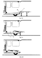
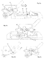
- the Fig. 1 presents a vehicle for transporting objects 2 such as a stretcher, an emergency response platform, for example in resuscitation, in surgery ... a coffin, any load to be moved in workshops, inter-flights, shipyards, shops or others.
- This vehicle has a transport volume and a door 3 closing an opening to introduce the object 2 in this volume.
- the Fig. 2 presents a trolley known from the prior art and intended to be embedded in a vehicle according to the invention.
- the carriage 2 comprises a carrying structure 4 intended to receive the object to be transported, such as a stretcher, a wheelchair, an emergency response platform, for example in intensive care, in surgery ... a coffin, a any load to move in workshops, entreplots, building sites, shops or other.
- This structure is supported by an anterior foot 5 provided with left and right side wheels 6 and a rear leg 7 provided with left and right side wheels 8.
- the two legs 5 and 7 are retractable and pivotally mounted to fold flat under the support structure 4, the unlocking of each foot to fold under the structure 4 is independent of one another.
- the feet 5 and 7 are placed in an almost vertical position as illustrated by the Fig. 2 and, when rolled into the vehicle, said feet are lying under the structure.
- the carriage rests at least on the wheels 6, and the two wheels 9.
- the front and rear legs 5 and 5 are pivotally mounted about an axis carried by the lateral legs of the structure 4, pivoting is free from front to back.
- the wheels 6 and 8 are mounted idle while the rollers 9 are mounted on the ends of the same axis 10 disposed transversely to the carriage.
- Horizontal handles 11 are placed at the rear of the supporting structure on each side of the carriage 2, these handles allow a person, an ambulance for example, to easily move the carriage.
- Two unlocking devices (not shown on the Fig. 2 ) unblock both feet independently, to bring them back under the structure. The locking of the feet in vertical position is carried out automatically at the end of pivoting.
- the controls of each unlocking device are made by levers accessible on the handles, on the same principle for example as that of the brake levers for a bicycle.
- the Fig. 3 .a shows a trolley intended to be loaded into a vehicle by the rear door.
- the present invention relates to any type of opening, whether it is lateral or rear.
- the ambulance driver positions the carriage in the axis of the vehicle facing the opening 20.
- the loading platform 21 of the vehicle ends at the rear by an inclined plane 22, having on each side flanks forming guides to the rollers 9 and the wheels 6 and 8. These flanks are narrowing and extend in the vehicle to guide the carriage towards the opening and bring it to a precise position of rolling inside.
- a base 23 is attached on this inclined plane and approximately halfway up.
- a hook 24 is fixed by a reversible connection to said base.
- the base comprises a groove into which the base of the hook slides, the opening of the groove being directed towards the rear of the vehicle.
- the hook 24 is attached to one end of a flexible link 26, the other end being rolled around the pulley of an electrically powered winch.
- the flexible link is preferably a strap, and may also be in the
- the ambulance driver pushes the trolley towards the vehicle and the rollers 9 come into contact with the inclined plane 22. Then moving a few centimeters, the axis 10 of the rollers 9 enters the opening of the hook 24.
- the Fig. 3 .b illustrates this step.
- the total introduction of the axis 10 of the rollers triggers on the one hand the closure of the hook on said axis and the release of the hook of the base 23.
- the carriage is now free to roll on the loading platform 21 of the vehicle.
- the ambulance driver presses a button of a control actuating the winch 25 to wind the flexible link.
- the flexible tie then pulls the hook towards the front of the vehicle.
- the carriage secured to the hook is driven inside the transport volume.
- the front foot 5 of the carriage abuts against the rear side of the vehicle.
- the ambulanceman unlocks the pivoting of the front foot 5 which pivots backwards and folds flat under the carrying structure.
- the weight of the carriage 2 and its load is supported by the wheels 6 and the rear wheels 8.
- the carriage retained by the flexible link can not return back by sliding on the inclined plane.
- the paramedic continues to press the button on the control.
- the hind foot abuts against the rear side of the vehicle.
- the person then unlocks the pivoting of the rear leg of this carriage with the help of another lever located on the other handle 11.
- the truck is fully loaded into the vehicle and the door can be closed.
- the carriage is automatically secured to the vehicle by means of fasteners incorporated in the loading platform, these means are typically three attachment points.
- the flexible link 26 is unrolled slightly so as to leave slack, and the hook 24 remains on the axis 10 of the front rollers.
- the movement of the carriage 2 is controlled by the winch 25 and the flexible link 26 in a smooth motion for a patient lying on the carriage and without effort for the ambulance. Even if the ground at the rear of the vehicle is below, the winch is powerful enough to hoist the truck and its load into the transport volume.
- the paramedic When disembarking, the paramedic has a second button triggering the unwinding of the flexible link. By maintaining this second button pressed, the operator exerts a slight pull back on the handles 11. The extraction of the carriage 2 is smooth and at a speed controlled by the rotation of the winch pulley.
- the rear wheels 8 When the rear wheels 8 are out, the paramedic maintains the carriage horizontally and the rear foot 7 is automatically unfolded in a vertical position, allowing the ambulance to no longer support the weight of the carriage at the rear. Then, the front wheels 6 come out and the front foot 5 is unfolded automatically in the vertical position.
- the rollers 9 come into contact with the inclined plane 22 and the hook returns to the base. The front of the truck descends and the wheels 6 of the front foot 5 rest on the ground smoothly.
- the hook 24 returns to the vertical and in contact with the base 23. This contact triggers on the one hand the opening of the hook thus releasing the axis 10 and other Its release on the base 23. Released from its hook, the ambulance can then pull the truck and take it away from the vehicle.
- the disembarkation of the trolley is therefore done with little effort for the paramedic and comfort for a patient on the trolley.
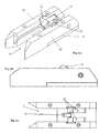
- the Fig. 4 .a, 4.b and 4.c show examples of diagrams of a base fixed on the inclined plane seen from several perspectives.
- the base is fixed by a fastener 30 to the base of the opening, on the inclined plane 22 for example.
- a throat 31 narrowing receives the hook and the guide in a precise position on the base.
- a pivoting abutment 33 secures the hook 24.
- This stop has a vertical flank cooperating with a side of the hook to retain it in its forward movement, especially when the carriage is shipped.
- the axis 10 approaches the base by the right side, the one opposite the groove 31.
- Two cams 32 placed on each side of the pivoting abutment sink under the action of the axis 10 during boarding and unlock the pivoting stop, thus releasing the hook 24 of the base.
- the Fig. 4 .b presents the base seen in profile. Both cams 32 are visible protruding from the upper surface of the base. The axis 10 comes into contact with the upper surface of the base and can thus lower the two cams.
- the Fig. 4 .c shows the base seen from above.
- the two cams 32 are visible on each side of the pivoting stop.
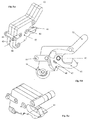
- the Fig. 5 .a, 5.b and 5.c shows diagrams of the hook 24 seen from several perspectives and according to an exemplary embodiment.
- the hook has an opening 40 adapted to receive the axis 10 of the rollers 9, this opening is closed on the axis with a clasp 41 pivoting about an axis 42.
- a finger 43 is fixed on the surface upper hook and is oriented obliquely in the direction of the opening 40. This finger can guide the axis in the opening in case the ground at the rear of the vehicle has a devers, which enhances the axis 10 relative to the base.
- an axis 44 allows the attachment of a terminal loop of the flexible link 26.
- This flexible link can easily be detached by removing a pin 45, thus releasing the axis 44 of the hook.
- a wheel 46 is placed below the axis 44 to roll the hook on the loading tray of the transport volume and thus prevent its friction.
- the Fig. 5 .b presents the hook 24 seen in profile.
- the movement of the clasp 41 about its axis of rotation 42 is clearly visible.
- the rotational movement is limited by a finger 47 sliding in a curved groove.
- a spring keeps the clasp in the closed position, and a pressure on a boss 48 in the lower part allows its rotation and its opening.
- the Fig. 5 .c presents the hook 24 viewed from perspective.
- the hook 41 is clearly visible.
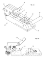
- the Fig. 6 .a and 6.b show the cooperation of the hook and its mounting base according to several perspectives and according to an exemplary embodiment.
- the Fig. 6 .a shows the approach of the axis 10 of the rollers 9, the position of the hook engaged in the groove 31 of the base 23.
- the Fig. 6 .b presents the hook and the profile base, with dotted internal elements seen in transparency.
- the base 23 and the hook 24 are typically made of PA6 type plastic.
- Other parts such as the cams 32 and the pivoting stop 33 are made of stainless steel.
- the Fig. 7 .a, 7.b and 7.c show the kinematics of the mechanical movements of the hook and the base during boarding, according to an exemplary embodiment.
- the Fig. 7 .a shows the position of the internal parts of the hook and the base during boarding, we can see the axis 10 which comes firstly in contact with the finger 43, which is guided towards the opening 40
- the hook is secured to the base 23 by means of two lugs taken in notches located on each side of the hook, thus preventing it from causing the hook to move backwards when the axis 10 of the carriage comes lean on the clasp to open it.
- the Fig. 7 .b shows the axis 10 penetrating into the opening of the hook.
- the axis exerts a pressure on an inclined plane of the clasp 41 which then lowers by pivoting about the axis 50.
- the axis 10 is inserted into the opening of the hook and the clasp is closed by the force of a spring, solidarisant the axis 10 of the carriage with the hook.
- closing the clasp 41 allows a game of about ten millimeters allowing the axis 10 to continue to advance in the opposite direction to the opening of the hook.
- the Fig. 7 .c shows the axis 10 inserted in the opening of the hook.
- the axis 10 reaches the bottom of the opening 40 of the hook and exerts a vertical pressure on the two cams 32 which pivot by pivoting in the base around a pivot axis 51.
- the pins connected the cams 32 then release the hook 24 of the base 23.
- the carriage releases the hook, the ambulance can then operate the winding of the flexible link to pull the carriage 2 effortlessly towards the front of the vehicle with the help of the winch 25.
- the Fig. 8 .a, 8.b, 8.c and 8.d show an example of kinematics of the mechanical movements of the hook and the base during the unloading of the carriage, according to an exemplary embodiment.
- the Fig. 8 .a shows the hook trapping the axis 10 to approach the base and is positioned in the groove 31.
- the Fig. 8 .b shows the hook completely positioned on the base.
- a stall stop 52 fixed on the base 30 comes into contact with the boss 48 of the hook and causes the clasp 41 to pivot.
- the clasp releases the axis 10 of the carriage.
- the pins lock the hook in the base, holding it ready for a new boarding of the truck.
- Fig. 8 .c presents the hook 24 in the open position without its base. Arrows show on the one hand the pivoting direction of the clasp and the place where the pressure of the stop 52 is exerted. Fig. 8 It can be seen that the rotational movement of the clasp 41 is limited by the pin 47 sliding in a groove curve.
- the Fig. 8 .d presents the hook 24 in the waiting position of the axis 10.
- Two notches 53 on each side and in the lower part of the hook are intended to receive the ends of the lugs. The insertion of the lugs in the notches secures the hook on the base.
- the winch control system 25 counts the turns of the pulley and stops at a determined number of turns. This number of laps is determined during boarding. In this way, the flexible link 26 is never unwound beyond the length allowing the hook 24 to be positioned on the base 23.
- the control system is paused. In standby mode, the consumption of the winch and its control system is minimal, thus saving the vehicle battery.
- the control system also goes to sleep when no command is introduced by the ambulance for a specified period, for example 30 seconds.
- a sensor detects the presence of the axis 10 on the base (in detecting for example that the cams 32 are in the lower position) thus allowing the winding of the flexible link if the paramedic orders it.
- the winch 25 is advantageously equipped with a disengaging device if an overcurrent is detected or if a force sensor detects excessive traction. An indicator light illuminates in this state indicating to the paramedic the presence of a defect.
- the winch 25 is controlled by a remote control unit with or without wire.
- the control box has at least two buttons, one to control the winding and unwinding of the winch.
- the connection between the winch 25 and the control box is done by radio, using two remote controls. These are removably attached by loop-hook fastening strips on the top of the right and left handles. The paramedic can thus operate with the thumb one or the other button while raising the handle with the other four fingers.
- the realized prototype comprises two remote controls with two buttons, each box is placed on the top of the horizontal handles of carriage transport.
- Each remote control can control the winding and unwinding of the winch.
- the operator maneuvers with one hand, the right hand for example, the lever to unlock the front foot 5, he uses the remote near his left hand.
- the lever to unlock the rear foot 7 he uses the remote near his right hand.
- the boarding movement is continuous and smooth.
- a third remote control can be hung inside the vehicle, to the left or right of the opening 20.
- the remote controls interact with the control system by two-way communication.
- the remote controls transmit control codes to the control system and receive instructions such as standby, signal warning of the limit switch, signal indicating overcurrent, ....
- the remotes also transmit their battery level allowing the system to tell the paramedic that it is time to change the batteries. Communication is secure and personalized, so if several vehicles are nearby, the remote controls are paired to a particular vehicle.
- the winch detects the end of the flexible link and its control system goes to sleep.
- the wakeup is performed by a specific combination of pressing the buttons for at least a certain duration, for example the winding button pressed on the right remote control and the unwinding button pressed on the remote control on the left, for 3 seconds .
- the alarm clock of the winch is indicated by a light on;
- the wheel 46 of the hook is guided during its journey to embarkation and disembarkation. In this way, during an unloading the hook returns exactly on the base after leaving it when boarding.
- These guide means are two rails fixed on the loading plate on each side of the tread of the wheel 46, where a groove made in the thickness of said loading plate.
- the invention is not limited to the embodiments of the subject of the invention since various modifications can be made without departing from its scope.
- the fastening of the hook on the carriage is effected everywhere type of means such as a horizontal beam or a vertical pin.
- the device of the invention is applicable to the driving and loading in a vehicle by a single person of a carriage for transporting and handling various loads and in particular a stretcher.
Landscapes
- Health & Medical Sciences (AREA)
- Public Health (AREA)
- Life Sciences & Earth Sciences (AREA)
- Animal Behavior & Ethology (AREA)
- General Health & Medical Sciences (AREA)
- Veterinary Medicine (AREA)
- Handcart (AREA)
Abstract
Description
- Le domaine de l'invention est celui des véhicules de transport de chariots dotés de roues. L'invention concerne plus particulièrement un moyen d'aide à l'embarquement du chariot dans le volume de transport.
- La présente invention concerne un véhicule de transport de chariots dotés de roues, notamment pour brancard de transport de personne ou d'un patient par ambulance.
- De tels chariots comportent une structure porteuse supérieure munie de moyens de fixation d'une charge telle que le brancard et supportée par deux pieds à roues latérales, l'un situé à l'avant et l'autre à l'arrière. Ces pieds sont éventuellement escamotables indépendamment l'un de l'autre. Chaque pied est monté pivotant sous la structure pour s'effacer de l'avant vers l'arrière, et est relié à cette structure par un moyen de verrouillage en position érigée et coopère avec un dispositif de commande de déverrouillage. La commande des moyens de verrouillage se situe à proximité immédiate des poignées de transport.
- Une personne, un ambulancier par exemple, tenant les poignées de transport du chariot à pieds escamotables, le présente devant l'ouverture du véhicule, le pied antérieur du chariot venant buter contre le flan arrière du véhicule, par exemple le plateau de chargement, le plancher ou le marchepied du véhicule. A l'aide d'une manette, la personne déverrouille le pivotement du pied antérieur, l'avant du chariot repose alors par deux roulettes antérieures posées sur la bande de roulement dans le véhicule. La personne continue à pousser le brancard à l'intérieur du véhicule jusqu'à ce que le pied postérieur vienne buter contre le flan arrière du véhicule. La personne déverrouille alors le pivotement de pied postérieur de ce chariot et termine l'introduction dans le véhicule, l'arrière du chariot reposant sur les roues du pied postérieur replié.
- Cette manoeuvre doit s'exécuter avec une sécurité absolue pour le malade ou le blessé transporté sur un brancard, quel que soit son poids notamment. Les moyens à mettre en oeuvre doivent être robustes, afin qu'ils ne puissent pas être détériorés et restent opérationnels si une fausse manoeuvre ou une action brutale se produit. Ainsi, le chariot ne doit pas s'affaisser lorsque la personne débloque le pied antérieur et ne doit pas non plus nécessiter un effort trop important pour hisser le chariot dans le véhicule
-
EP 1585 474 publiée le 19 Octobre 2005 , décrit un système constitué d'une civière d'ambulance monté sur un socle doté de roues et d'un dispositif de chargement pour la charger dans un véhicule de transport. La civière est posée sur un chariot doté d'un arceau qui est pris par un crochet à l'extrémité d'une flèche allongée qui tracte la civière dans le véhicule. - La demande
US2004/202533 publiée le 14 Octobre 2004 , décrit le chargement d'un lit dans un véhicule. Le véhicule comporte un treuil enroulant un câble pour tirer le lit sur une rampe de chargement et sur une surface de transport délimité à l'intérieur du véhicule par des parois formant un baquet pour le blocage. - Le document
WO 2006/003385 décrit un système d'embarquement d'un lit roulant dans un véhicule. Le système comporte notamment un rail fixé sur le sol du véhicule, et un chariot glissant dans le rail et entraîné par un moteur. - L'invention a notamment pour objectif d'apporter une solution efficace à au moins certains de ces différents problèmes cités précédemment. En particulier, selon au moins un mode de réalisation, un objectif de l'invention est de fournir un véhicule équipé d'un système d'aide à l'embarquement et/ou débarquement d'un chariot dotés de roues.
- Pour ceci, l'invention propose un véhicule de transport d'un chariot comportant une ouverture et un plateau de chargement destiné à recevoir en roulant ledit chariot. Le véhicule comporte notamment un crochet fixé par un dispositif de solidarisation réversible à une embase attachée au plateau de chargement du véhicule. L'introduction d'une pièce dudit chariot dans une ouverture du crochet déclenche la fermeture du crochet sur ladite pièce par un fermoir pivotant autour d'un axe et la libération par le dispositif de solidarisation réversible du crochet de l'embase. Le crochet solidarisé avec le chariot est tracté par un lien souple enroulant dans un treuil fixé dans le véhicule. Le véhicule comporte en outre des moyens de guidage aptes à placer le crochet à la verticale et au contact de l'embase lorsque le chariot est extrait du véhicule, le contact du crochet sur le dispositif de solidarisation réversible déclenche l'ouverture du crochet pour libérer la pièce dudit chariot et la solidarisation du crochet sur l'embase.
- De cette manière, le chariot est automatiquement solidarisé au crochet en le poussant dessus. L'ambulancier n'a plus qu'à actionner le treuil pour déclencher l'embarquement du chariot dans le véhicule, et le système d'aide fonctionne automatiquement lors du débarquement du chariot.
- Selon un autre mode de réalisation, le dispositif de solidarisation comporte une came pivotante reliée à un ergot libérant le crochet. La pièce du chariot exerce une pression verticale sur au moins une came pour la faire pivoter lorsque la pièce se trouve dans l'ouverture du crochet. De cette manière, le mécanisme de décrochage du crochet est simple et de maintenance facile.
- Selon un autre mode de réalisation, le crochet fermé autorise un déplacement de la pièce du chariot sur une longueur déterminé. De cette manière, le crochet peut se refermer sur la pièce avant de se décrocher sur l'embase, l'écart de temps correspond au déplacement de la pièce du chariot dans le crochet fermé.
- Selon un autre mode de réalisation, le fermoir comporte un bossage en partie basse destiné à entrer en contact avec au moins une butée de décrochage fixée sur l'embase, et le mouvement du crochet vers l'embase lorsque le bossage est en contact avec la butée de décrochage fait pivoter le fermoir en position ouverte. De cette manière, le fermoir s'ouvre automatiquement pour libérer la pièce.
- Selon un autre mode de réalisation, le crochet comporte deux encoches destinées à recevoir des ergots fixés sur l'embase, l'insertion des ergots dans les encoches solidarise le crochet sur l'embase. De cette manière, le crochet est bien fixé sur l'embase.
- Selon un autre mode de réalisation, le véhicule comporte un système de contrôle du treuil, ce système est en communication avec au moins deux télécommandes. De cette manière, l'ambulancier peut commander le système d'embarquement par deux moyens de commandes.
- Selon un autre mode de réalisation, une des deux télécommandes est fixée de façon amovible sur la poignée droite et l'autre sur la poignée gauche, chaque télécommande commande indifféremment l'enroulage et le déroulage du lien souple dans le treuil. De cette manière, l'ambulancier peut commander avec l'une ou l'autre mains le treuil tout en gardant au moins une main sur le chariot.
- Selon un autre mode de réalisation, le système de contrôle et les télécommandes disposent d'un mode de veille dans lequel le treuil et le système de contrôle ont une consommation minimale, ce mode est déclenché au moins après une durée déterminée sans introduction de commandes sur lesdites télécommandes. De cette manière, le système s'inactive automatiquement après une période durant lequel il n'est pas utilisé.
- Selon un autre mode de réalisation, le crochet comporte une roue et le véhicule comporte un moyen de guidage utilisant cette roue pour guider le déplacement du crochet lors de l'enroulage et le déroulage du lien souple. De cette manière, le crochet revient exactement sur l'embase lors d'un débarquement du chariot.
- D'autres caractéristiques et avantages de l'invention apparaîtront à la lecture de la description suivante de modes de réalisation particuliers, donnée à titre de simple exemple illustratif et non limitatif, et des dessins annexés parmi lesquels :
- la
figure 1 présente un véhicule destiné à transporter un chariot selon l'art antérieur, - la
figure 2 illustre un chariot à pied escamotable connu de l'art antérieur - les
figures 3.a ,3.b, 3.c et 3.d présentent un exemple de cinématique des étapes d'embarquement d'un chariot dans un véhicule selon l'invention, - les
figures 4.a, 4.b et 4.c présente des exemples de schémas d'une embase attachée sur un plan incliné vue selon plusieurs perspectives, - les
figures 5.a, 5.b et 5.c présente des schémas du crochet vu selon plusieurs perspectives selon un exemple de réalisation, - les
figures 6.a et 6.b présentent la coopération du crochet et de son embase de fixation selon plusieurs perspectives et selon un exemple de réalisation, - les
figures 7.a, 7.b, et 7.c présentent un exemple de cinématique des mouvements mécaniques du crochet et l'embase lors de l'embarquement, - les
figures 8.a, 8.b, 8.c et 8.d présentent un exemple de cinématique des mouvements mécaniques du crochet et l'embase lors du débarquement. - La présente invention concerne un véhicule de transport d'un chariot comportant une ouverture et un plateau de chargement destiné à recevoir en roulant ledit chariot. Le véhicule comporte également un dispositif d'aide à l'embarquement et au débarquement du chariot comportant notamment un crochet, une embase et un treuil. Le crochet est fixé par un dispositif de solidarisation réversible à l'embase attachée au plateau de chargement du véhicule. L'introduction d'une pièce du chariot dans une ouverture du crochet déclenche la fermeture du crochet sur cette pièce et la libération par le dispositif de solidarisation réversible du crochet de l'embase. Le crochet solidarisé avec le chariot est tracté par un lien souple s'enroulant dans un treuil fixé dans le véhicule. Une fois le crochet arrimé sur le chariot, l'ambulancier n'a plus qu'à lancer l'enroulement du lien souple autour du treuil pour embarquer le chariot dans le véhicule. L'opération de solidarisation est réversible et le crochet libère la pièce du chariot et se solidarise de nouveau sur l'embase lors du débarquement du chariot.
- La
Fig. 1 présente un véhicule destiné à transporter des objets 2 tels qu'un brancard, une plateforme d'intervention d'urgence, par exemple en réanimation, en chirurgie... un cercueil, une charge quelconque à déplacer dans des ateliers, des entreponts, des chantiers, des magasins ou autres. Ce véhicule dispose d'un volume de transport et d'une porte 3 fermant une ouverture pour introduire l'objet 2 dans ce volume. - La
Fig. 2 présente un chariot connu de l'art antérieur et destiné à être embarqué dans un véhicule selon l'invention. - Le chariot 2 comprend une structure porteuse 4 destinée à recevoir l'objet à transporter, tel qu'un brancard, un fauteuil roulant, une plateforme d'intervention d'urgence, par exemple en réanimation, en chirurgie... un cercueil, une charge quelconque à déplacer dans des ateliers, des entreponts, des chantiers, des magasins ou autres. Cette structure est supportée par un pied antérieur 5 muni de roulettes latérales gauche et droite 6 et par un pied postérieur 7 muni de roulettes latérales gauche et droite 8. Selon un exemple préféré de réalisation, les deux pieds 5 et 7 sont escamotables et montés pivotants pour se replier à plat sous la structure porteuse 4, le déverrouillage de chaque pied pour les replier sous la structure 4 est indépendant l'un de l'autre. Lorsque le chariot est opérationnel, les pieds 5 et 7 sont placés en position quasi verticale comme illustré par la
Fig. 2 et, lorsqu'il est roulé dans le véhicule, lesdits pieds sont couchés sous la structure. En position embarquée, le chariot repose au moins sur les roues 6, et les deux roulettes 9. A leurs extrémités hautes, les pieds antérieurs 5 et postérieurs 7 sont montés pivotants autour d'un axe porté par des pattes latérales de la structure 4, le pivotement est libre de l'avant vers l'arrière. - Les roues 6 et 8 sont montées folles tandis que les roulettes 9 sont montées sur les extrémités d'un même axe 10 disposé transversalement au chariot. Des poignées horizontales 11 sont placées à l'arrière de la structure porteuse de chaque coté du chariot 2, ces poignées permettent à une personne, un ambulancier par exemple, de déplacer facilement le chariot. Deux dispositifs de déverrouillage (non représentés sur la
Fig. 2 ) débloquent l'un et l'autre pied de façon indépendante, pour les ramener sous la structure. Le verrouillage des pieds en position verticale s'effectue automatiquement en fin de pivotement. Les commandes de chaque dispositif de déverrouillage s'effectuent par des manettes accessibles sur les poignées, sur le même principe par exemple que celui des manettes de frein pour un vélo. - La
Fig. 3 .a montre un chariot destiné à être embarqué dans un véhicule par la porte arrière. La présente invention concerne tout type d'ouverture, qu'elle soit latérale ou arrière. L'ambulancier positionne le chariot dans l'axe du véhicule face à l'ouverture 20. Le plateau de chargement 21 du véhicule se termine à l'arrière par un plan incliné 22, comportant de chaque coté des flancs formant des guides aux roulettes 9 et aux roues 6 et 8. Ces flancs vont en se rétrécissant et se prolongent dans le véhicule afin de guider le chariot vers l'ouverture et l'amener à une position précise de roulage à l'intérieur. Une embase 23 est attachée sur ce plan incliné et approximativement à mi-hauteur. Un crochet 24 est fixé par une solidarisation réversible à ladite embase. L'embase comporte une gorge dans laquelle se glisse la base du crochet, l'ouverture de la gorge étant orientée vers l'arrière du véhicule. Le crochet 24 est fixé à une extrémité d'un lien souple 26, l'autre extrémité étant roulée autour de la poulie d'un treuil 25 motorisé électriquement. Le lien souple est de préférence une sangle, et peut aussi être réalisé sous la forme d'un câble ou d'une chaîne. - L'ambulancier pousse le chariot en direction du véhicule et les roulettes 9 entrent en contact avec le plan incliné 22. Puis en avançant de quelques centimètres, l'axe 10 des roulettes 9 entre dans l'ouverture du crochet 24. La
Fig. 3 .b illustre cette étape. L'introduction totale de l'axe 10 des roulettes déclenche d'une part la fermeture du crochet sur ledit axe et la libération du crochet de l'embase 23. Nous expliquerons par la suite un mode particulier de réalisation d'un crochet et de son embase associée. Le chariot est désormais libre de rouler sur le plateau de chargement 21 du véhicule. - Lors de l'étape illustrée par la
Fig. 3.C , l'ambulancier appuie sur un bouton d'une commande actionnant le treuil 25 pour enrouler le lien souple. Le lien souple tire alors le crochet vers l'avant du véhicule. Le chariot solidarisé avec le crochet est entraîné à l'intérieur du volume de transport. Le pied antérieur 5 du chariot vient buter contre le flan arrière du véhicule. A l'aide d'une manette se situant sur une des deux poignées 11, l'ambulancier déverrouille le pivotement du pied antérieur 5 qui pivote vers l'arrière et se replie à plat sous la structure porteuse. A ce moment, le poids du chariot 2 et de son chargement est supporté par les roulettes 6 et par les roues arrières 8. Le chariot retenu par le lien souple ne peut revenir en arrière en glissant sur le plan incliné. L'ambulancier continue d'appuyer sur le bouton de la commande. A un certain moment, le pied postérieur vient buter contre le flan arrière du véhicule. La personne déverrouille alors le pivotement du pied postérieur de ce chariot à l'aide d'une autre manette se situant sur l'autre poignée 11. - A l'étape illustrée par la
Fig. 3 .d, le chariot est totalement embarqué dans le véhicule et la porte peut être refermée. Le chariot se solidarise automatiquement au véhicule à l'aide de moyens de fixations incorporés dans le plateau de chargement, ces moyens sont typiquement trois points de fixation. Le lien souple 26 est déroulé légèrement de façon à laisser du mou, et le crochet 24 reste sur l'axe 10 des roulettes avant. - A l'aide du prototype réalisé, on constate que le déplacement du chariot 2 est contrôlé par le treuil 25 et le lien souple 26 dans un mouvement sans à-coups pour un patient allongé sur le chariot et sans efforts pour l'ambulancier. Même si le terrain à l'arrière du véhicule est en contrebas, le treuil est suffisamment puissant pour hisser le chariot et son chargement dans le volume de transport.
- Lors du débarquement, l'ambulancier dispose d'un second bouton déclenchant le déroulage du lien souple. En maintenant ce second bouton enfoncé, l'opérateur exerce une légère traction vers l'arrière sur les poignées 11. L'extraction du chariot 2 s'effectue sans à-coups et à une vitesse contrôlée par la rotation de la poulie du treuil. Lorsque les roues arrières 8 sont sorties, l'ambulancier maintient le chariot à l'horizontale et le pied postérieur 7 vient se déplier automatiquement en position verticale, permettant ainsi à l'ambulancier de ne plus supporter le poids du chariot à l'arrière. Puis, les roues avant 6 sortent et le pied antérieur 5 vient se déplier automatiquement en position verticale. Les roulettes 9 entrent en contact avec le plan incliné 22 et le crochet revient sur l'embase. L'avant du chariot descend et les roues 6 du pied antérieur 5 reposent sur le sol en douceur. Selon un perfectionnement, guidé par les flancs du plan incliné, le crochet 24 revient à la verticale et au contact de l'embase 23. Ce contact déclenche d'une part l'ouverture du crochet libérant ainsi l'axe 10 et d'autre part sa fixation sur l'embase 23. Libéré de son crochet, l'ambulancier peut alors tirer le chariot et l'emmener loin du véhicule.
- Le débarquement du chariot s'effectue donc avec peu d'efforts pour l'ambulancier et du confort pour un patient sur le chariot.
- Les
Fig. 4 .a, 4.b et 4.c présentent des exemples de schémas d'une embase fixée sur le plan incliné vue selon plusieurs perspectives. L'embase est fixée par une fixation 30 à la base de l'ouverture, sur le plan incliné 22 par exemple. Une gorge 31 se rétrécissant reçoit le crochet et le guide dans une position précise sur l'embase. Une butée pivotante 33 assure la fixation du crochet 24. Cette butée comporte un flanc vertical coopérant avec un flanc du crochet pour le retenir dans son déplacement vers l'avant, notamment lorsque le chariot est embarqué. Lors de l'embarquement du chariot, l'axe 10 s'approche de l'embase par le coté droit, celui opposé à la gorge 31. Deux cames 32 placées de chaque coté de la butée pivotante s'enfoncent sous l'action de l'axe 10 lors de l'embarquement et débloquent la butée pivotante, libérant ainsi le crochet 24 de l'embase. - La
Fig. 4 .b présente l'embase vue de profil. Les deux cames 32 sont visibles en dépassant de la surface supérieure de l'embase. L'axe 10 vient en contact avec la surface supérieure de l'embase et peut ainsi abaisser les deux cames. - La
Fig. 4 .c présente l'embase vue du dessus. Les deux cames 32 sont visibles de chaque coté de la butée pivotante. - Les
Fig. 5 .a, 5.b et 5.c présente des schémas du crochet 24 vu selon plusieurs perspectives et selon un exemple de réalisation. Le crochet comporte une ouverture 40 apte à recevoir l'axe 10 des roulettes 9, cette ouverture se referme sur l'axe à l'aide d'un fermoir 41 pivotant autour d'un axe 42. Un doigt 43 est fixé sur la surface supérieure du crochet et est orienté en oblique dans la direction de l'ouverture 40. Ce doigt permet de guider l'axe dans l'ouverture au cas où le sol à l'arrière du véhicule présente un devers, ce qui rehausse l'axe 10 par rapport à l'embase. - A l'arrière du crochet, c'est à dire du coté opposé à l'ouverture, un axe 44 permet l'accrochage d'une boucle terminale du lien souple 26. Ce lien souple peut facilement se détacher en enlevant une goupille 45, libérant ainsi l'axe 44 du crochet. Une roulette 46 est placée en-dessous de l'axe 44 pour faire rouler le crochet sur le plateau de chargement du volume de transport et ainsi éviter son frottement.
- La
Fig. 5 .b présente le crochet 24 vu de profil. Le mouvement du fermoir 41 autour de son axe de rotation 42 est clairement visible. Le mouvement de rotation est limité par un doigt 47 coulissant dans une gorge courbe. Un ressort maintient le fermoir en position fermée, et une pression sur un bossage 48 en partie basse permet sa rotation et son ouverture. - La
Fig. 5 .c présente le crochet 24 vu de perspective. Le crochet 41 est clairement visible. - Les
Fig. 6 .a et 6.b présentent la coopération du crochet et de son embase de fixation selon plusieurs perspectives et selon un exemple de réalisation. - La
Fig. 6 .a montre l'approche de l'axe 10 des roulettes 9, la position du crochet engagé dans la gorge 31 de l'embase 23. - La
Fig. 6 .b présente le crochet et l'embase de profil, avec en pointillé des éléments internes vus en transparence. - L'embase 23 et le crochet 24 sont typiquement fabriqués en matière plastique de type PA6. D'autres pièces telles que les cames 32 et la butée pivotante 33, sont en acier inoxydable.
- Les
Fig. 7 .a, 7.b et 7.c présentent la cinématique des mouvements mécaniques du crochet et l'embase lors de l'embarquement, selon un exemple de réalisation. LaFig. 7 .a montre la position des pièces internes du crochet et de l'embase lors de l'embarquement, on peut voir l'axe 10 qui vient dans un premier temps en contact avec le doigt 43, qui se trouve guider vers l'ouverture 40 du crochet 24. Le crochet est solidarisé avec l'embase 23 à l'aide de deux ergots pris dans des encoches situés de chaque coté du crochet, l'empêchant ainsi de faire partir en arrière le crochet lorsque l'axe 10 du chariot vient s'appuyer sur le fermoir pour l'ouvrir. - La
Fig. 7 .b montre l'axe 10 pénétrant dans l'ouverture du crochet. L'axe exerce une pression sur un plan incliné du fermoir 41 qui s'abaisse alors en pivotant autour de l'axe 50. L'axe 10 s'insère dans l'ouverture du crochet et le fermoir se referme par la force d'un ressort, solidarisant l'axe 10 du chariot avec le crochet. Selon l'exemple de réalisation, la fermeture du fermoir 41 autorise un jeu d'une dizaine de millimètres permettant à l'axe 10 de continuer à avancer dans la direction opposé à l'ouverture du crochet. - La
Fig. 7 .c montre l'axe 10 inséré dans l'ouverture du crochet. Le fermoir étant fermé, l'axe 10 atteint le fond de l'ouverture 40 du crochet et exerce une pression verticale sur les deux cames 32 qui s'enfoncent en pivotant dans l'embase autour d'un axe pivot 51. Les ergots reliés aux cames 32 libèrent alors le crochet 24 de l'embase 23. En continuant à avancer vers l'avant du véhicule, le chariot libère le crochet, l'ambulancier peut alors actionner l'enroulage du lien souple pour tirer sans effort le chariot 2 vers l'avant du véhicule avec l'aide du treuil 25. - Les
Fig. 8 .a, 8.b, 8.c et 8.d présentent un exemple de cinématique des mouvements mécaniques du crochet et l'embase lors du débarquement du chariot, selon un exemple de réalisation. LaFig. 8 .a montre le crochet emprisonnant l'axe 10 s'approcher de l'embase et se positionne dans la gorge 31. - La
Fig. 8 .b montre le crochet complétement positionné sur l'embase. Une butée de décrochage 52 fixée sur l'embase 30 vient en contact avec le bossage 48 du crochet et provoque le pivotement du fermoir 41. En pivotant, le fermoir libère l'axe 10 du chariot. Dans le même temps, les ergots bloquent le crochet dans l'embase, le tenant prêt pour un nouvel embarquement du chariot. - La
Fig. 8 .c présente le crochet 24 en position d'ouverture sans son embase. Des flèches montrent d'une part le sens de pivotement du fermoir et l'endroit où s'exerce la pression de la butée 52. Sur lesFig. 8 , on peut constater que le mouvement de rotation du fermoir 41 est limité par le doigt 47 coulissant dans une gorge courbe. - La
Fig. 8 .d présente le crochet 24 en position d'attente de l'axe 10. Deux encoches 53 de chaque coté et en partie basse du crochet sont destinées à recevoir les extrémités des ergots. L'insertion des ergots dans les encoches solidarise le crochet sur l'embase. - Selon un perfectionnement, lors du débarquement le système de contrôle du treuil 25 compte les tours de la poulie et s'arrête à un nombre de tours déterminé. Ce nombre de tours est déterminé lors de l'embarquement. De cette manière, le lien souple 26 n'est jamais déroulé au delà de la longueur permettant au crochet 24 de se positionner sur l'embase 23. Lorsque le treuil s'arrête avec le lien souple en bout de course, le système de contrôle est mis en veille. En mode veille, la consommation du treuil et de son système de contrôle est minimale, économisant ainsi la batterie du véhicule. Le système de contrôle se met également en veille lorsqu'aucune commande n'est introduite par l'ambulancier pendant une durée déterminée, 30 secondes par exemple. Selon un perfectionnement, un capteur détecte la présence de l'axe 10 sur l'embase (en détectant par exemple que les cames 32 sont en position basse) autorisant ainsi l'enroulage du lien souple si l'ambulancier le commande. Le treuil 25 est avantageusement équipé d'un dispositif de débrayage si une surintensité est détectée ou si un capteur d'effort détecte une traction trop importante. Un voyant lumineux s'allume dans cet état indiquant à l'ambulancier la présence d'un défaut.
- Selon un perfectionnement, lorsque une surintensité ou un effort dépassant un seuil est détectée, l'enroulage du lien souple autour de la poulie du treuil s'arrête, le système de contrôle du moteur exécute un quart de rotation inverse de la poulie pour éviter de maintenir le lien souple sous tension. Selon un perfectionnement, un avertisseur sonore (buzzer) et/ou lumineux est placé en hauteur dans le volume de chargement afin d'avertir l'ambulancier de certaines situations telles que :
- enroulage, déroulage du lien souple,
- détection d'une surintensité,
- mise en mode veille, réveil du système,
- indication du niveau faible des piles des télécommandes,
- etc
- La commande du treuil 25 s'effectue par un boîtier de commande déporté avec ou sans fil. Le boitier de commande comporte au moins deux boutons, l'un pour contrôler l'enroulage et le déroulage du treuil. Selon un mode préféré de réalisation utilisé dans le prototype réalisé, la liaison entre le treuil 25 et le boitier de commande s'effectue par radio, à l'aide de deux télécommandes. Celles-ci sont fixées de façon amovible, par des bandes de fixation de type boucle - crochet sur le dessus des poignées droite et gauche. L'ambulancier peut ainsi actionner avec le pouce l'un ou l'autre bouton tout en soulevant la poignée avec les quatre autres doigts.
- Le prototype réalisé comporte deux télécommandes à deux boutons, chaque boitier est placé sur le dessus des poignées horizontales de transport du chariot. Chaque télécommande peut contrôler l'enroulage et le déroulage du treuil. Lorsque l'opérateur manoeuvre d'une main, la main droite par exemple, la manette pour déverrouiller le pied antérieur 5, il utilise la télécommande à proximité de la main gauche. Puis, lorsqu'il manoeuvre avec la main gauche la manette pour déverrouiller le pied postérieur 7, il utilise la télécommande près de la main droite. De cette manière, le mouvement d'embarquement est continu et sans à-coup. Selon un perfectionnement, une troisième télécommande peut être accroché à l'intérieur du véhicule, à gauche ou à droite de l'ouverture 20.
- Selon un autre perfectionnement, les télécommandes dialoguent avec le système de contrôle par une communication bidirectionnelle. Les télécommandes transmettent des codes de commande vers le système de contrôle et reçoivent des instructions telles que mise en veille, signal avertissant de la fin de course, signal indiquant une surintensité, .... Les télécommandes transmettent aussi leur niveau de pile permettant au système de contrôle d'indiquer à l'ambulancier qu'il est temps de changer les piles. La communication est sécurisée et personnalisée, de cette façon, si plusieurs véhicules se trouvent à proximité, les télécommandes sont appariées à un véhicule en particulier.
- Selon un autre perfectionnement, lorsque le chariot est complétement débarqué du véhicule, le treuil détecte la fin de course du lien souple et son système de contrôle se met en veille. Le réveil s'effectue par une combinaison spécifique d'appuie sur les boutons pendant au moins une durée déterminée, par exemple le bouton d'enroulage enfoncé sur la télécommande de droite et le bouton de déroulage enfoncé sur la télécommande de gauche, pendant 3 secondes. Le réveil du treuil est signalé par un voyant lumineux allumé ;
- Selon un autre perfectionnement, la roue 46 du crochet est guidée lors de son déplacement à l'embarquement et au débarquement. De cette manière, lors d'un débarquement le crochet revient exactement sur l'embase après l'avoir quittée lors de l'embarquement. Ces moyens de guidage sont deux rails fixés sur le plateau de chargement de chaque coté de la bande de roulement de la roue 46, où une gorge pratiquée dans l'épaisseur dudit plateau de chargement.
- L'invention n'est pas limitée aux formes de réalisation de l'objet de l'invention car diverses modifications peuvent y être apportées sans sortir de son cadre. La solidarisation du crochet sur le chariot s'effectue partout type de moyen tel qu'un longeron horizontal ou un plot vertical. Le dispositif de l'invention est applicable à la conduite et au chargement dans un véhicule par une seule personne d'un chariot de transport et de manipulation de charges diverses et notamment d'un brancard.
Claims (9)
- Véhicule de transport d'un chariot comportant une ouverture, un plateau de chargement destiné à recevoir en roulant ledit chariot et un crochet (24) fixé par un dispositif de solidarisation réversible à une embase (23) attachée au plateau de chargement du véhicule, l'introduction d'une pièce (10) dudit chariot dans une ouverture (40) du crochet déclenchant la fermeture du crochet sur ladite pièce par un fermoir (41) pivotant autour d'un axe (42) et la libération par le dispositif de solidarisation réversible du crochet de l'embase (23), ledit crochet (24) solidarisé avec le chariot (2) étant tracté par un lien souple (26) s'enroulant dans un treuil fixé dans le véhicule, caractérisé en ce qu'il comporte des moyens de guidage aptes à placer le crochet (24) à la verticale et au contact de l'embase lorsque le chariot est extrait du véhicule, le contact du crochet sur le dispositif de solidarisation réversible déclenche l'ouverture du crochet pour libérer la pièce (10) dudit chariot et la solidarisation du crochet sur l'embase.
- Véhicule de transport selon la revendication 1, caractérisé en ce que le dispositif de solidarisation comporte au moins une came pivotante (32) reliée à un ergot libérant le crochet (24), ladite pièce exerçant une pression verticale sur l'au moins une came pour la faire pivoter lorsque la pièce se trouve dans l'ouverture (40) du crochet.
- Véhicule de transport selon la revendication 2, caractérisé en ce que le crochet fermé autorise un déplacement de ladite pièce (10) du chariot sur une longueur déterminé.
- Véhicule de transport selon l'une quelconque des revendications précédentes, caractérisé en ce que ledit fermoir comporte un bossage en partie basse destiné à entrer en contact avec au moins une butée de décrochage (52) fixée sur l'embase, le mouvement du crochet vers l'embase lorsque le bossage est en contact avec la butée de décrochage faisant pivoter le fermoir en position ouverte.
- Véhicule de transport selon la revendication 4, caractérisé en ce que le crochet comporte deux encoches destinées à recevoir des ergots fixés sur l'embase, l'insertion des ergots dans les encoches solidarise le crochet sur l'embase.
- Véhicule de transport selon l'une quelconque des revendications précédentes, caractérisé en ce qu'il comporte en outre un système de contrôle du treuil, ledit système étant en communication avec au moins deux télécommandes.
- Véhicule de transport selon la revendication 6, caractérisé en ce qu'une des deux au moins télécommandes est fixée de façon amovible sur la poignée droite et l'autre sur la poignée gauche, chaque télécommande commandant indifféremment l'enroulage et le déroulage du lien souple (26) dans le treuil.
- Véhicule de transport selon l'une quelconque des revendications 6 ou 7, caractérisé en ce que le système de contrôle et les télécommande disposent d'un mode de veille dans lequel le treuil et le système de contrôle ont une consommation minimale, ce mode étant déclenché au moins après une durée déterminée sans introduction de commandes sur lesdites télécommandes.
- Véhicule de transport selon l'une quelconque des revendications précédentes, caractérisé en ce que le crochet comporte une roue (46), le véhicule comportant un moyen de guidage utilisant la roue pour guider le déplacement du crochet lors de l'enroulage et le déroulage du lien souple (26).
Applications Claiming Priority (1)
| Application Number | Priority Date | Filing Date | Title |
|---|---|---|---|
| FR1456881A FR3023709A1 (fr) | 2014-07-17 | 2014-07-17 | Vehicule de transport de brancard avec un dispositif d'aide a l'embarquement |
Publications (2)
| Publication Number | Publication Date |
|---|---|
| EP2974704A1 true EP2974704A1 (fr) | 2016-01-20 |
| EP2974704B1 EP2974704B1 (fr) | 2016-12-28 |
Family
ID=52003934
Family Applications (1)
| Application Number | Title | Priority Date | Filing Date |
|---|---|---|---|
| EP15177152.4A Not-in-force EP2974704B1 (fr) | 2014-07-17 | 2015-07-16 | Véhicule de transport de brancard avec un dispositif d'aide à l'embarquement |
Country Status (4)
| Country | Link |
|---|---|
| EP (1) | EP2974704B1 (fr) |
| ES (1) | ES2619318T3 (fr) |
| FR (1) | FR3023709A1 (fr) |
| PT (1) | PT2974704T (fr) |
Cited By (3)
| Publication number | Priority date | Publication date | Assignee | Title |
|---|---|---|---|---|
| EP3791846A1 (fr) * | 2019-09-13 | 2021-03-17 | Cdc Group | Dispositif d'arrimage de chargement et/ou d'extraction motorises d'un chariot portant un brancard, recepteur et ambulance associes |
| CN113558879A (zh) * | 2021-07-17 | 2021-10-29 | 尹玉琴 | 一种便于上下救护车的紧急救护担架 |
| EP4162909A1 (fr) * | 2021-10-07 | 2023-04-12 | Stem S.r.l. | Brancard d'ambulance |
Families Citing this family (1)
| Publication number | Priority date | Publication date | Assignee | Title |
|---|---|---|---|---|
| US11059408B2 (en) | 2018-10-08 | 2021-07-13 | David P. Murphy | Mortuary cargo loading system and method |
Citations (4)
| Publication number | Priority date | Publication date | Assignee | Title |
|---|---|---|---|---|
| US20040080172A1 (en) * | 2002-10-18 | 2004-04-29 | Mitchell Donald E. | Bariatric gurney and process |
| US20040202533A1 (en) | 2003-04-08 | 2004-10-14 | Haire A. Ralph | Bed containment system for vehicles |
| EP1585474A2 (fr) | 2003-01-15 | 2005-10-19 | Stryker Corporation a Corporation of the State of Michigan | Dispositif de chargement et de dechargement de civiere d'ambulance |
| WO2006003385A1 (fr) | 2004-06-30 | 2006-01-12 | Glide-Rite Products Ltd | Dispositif de manutention de charge |
-
2014
- 2014-07-17 FR FR1456881A patent/FR3023709A1/fr active Pending
-
2015
- 2015-07-16 EP EP15177152.4A patent/EP2974704B1/fr not_active Not-in-force
- 2015-07-16 PT PT151771524T patent/PT2974704T/pt unknown
- 2015-07-16 ES ES15177152.4T patent/ES2619318T3/es active Active
Patent Citations (4)
| Publication number | Priority date | Publication date | Assignee | Title |
|---|---|---|---|---|
| US20040080172A1 (en) * | 2002-10-18 | 2004-04-29 | Mitchell Donald E. | Bariatric gurney and process |
| EP1585474A2 (fr) | 2003-01-15 | 2005-10-19 | Stryker Corporation a Corporation of the State of Michigan | Dispositif de chargement et de dechargement de civiere d'ambulance |
| US20040202533A1 (en) | 2003-04-08 | 2004-10-14 | Haire A. Ralph | Bed containment system for vehicles |
| WO2006003385A1 (fr) | 2004-06-30 | 2006-01-12 | Glide-Rite Products Ltd | Dispositif de manutention de charge |
Cited By (5)
| Publication number | Priority date | Publication date | Assignee | Title |
|---|---|---|---|---|
| EP3791846A1 (fr) * | 2019-09-13 | 2021-03-17 | Cdc Group | Dispositif d'arrimage de chargement et/ou d'extraction motorises d'un chariot portant un brancard, recepteur et ambulance associes |
| FR3100712A1 (fr) * | 2019-09-13 | 2021-03-19 | Cdc Group | Dispositif d’arrimage de chargement et/ou d’extraction motorises d’un chariot portant un brancard, recepteur et ambulance associes |
| CN113558879A (zh) * | 2021-07-17 | 2021-10-29 | 尹玉琴 | 一种便于上下救护车的紧急救护担架 |
| CN113558879B (zh) * | 2021-07-17 | 2023-07-28 | 广东来纳特种车辆制造有限公司 | 一种便于上下救护车的紧急救护担架 |
| EP4162909A1 (fr) * | 2021-10-07 | 2023-04-12 | Stem S.r.l. | Brancard d'ambulance |
Also Published As
| Publication number | Publication date |
|---|---|
| PT2974704T (pt) | 2017-03-23 |
| FR3023709A1 (fr) | 2016-01-22 |
| ES2619318T3 (es) | 2017-06-26 |
| EP2974704B1 (fr) | 2016-12-28 |
Similar Documents
| Publication | Publication Date | Title |
|---|---|---|
| EP2974704B1 (fr) | Véhicule de transport de brancard avec un dispositif d'aide à l'embarquement | |
| CA1175336A (fr) | Dispositif de securite pour le transport dans un vehicule d'une personne circulant en fauteuil roulant | |
| US20100124476A1 (en) | Cylinder cart having a retention hook | |
| EP3035900B1 (fr) | Dispositif de distribution de véhicules individuels, tels que fauteuil roulant ou scooter, pour automobilistes handicapés moteurs et son procédé de mise en oeuvre | |
| US20070029267A1 (en) | Bicycle support rack | |
| US5649803A (en) | Motorcycle ramp | |
| BR112018074191B1 (pt) | Aparelho de guincho adaptado para puxar e dirigir um dispositivo de mobilidade para cima e para baixo na inclinação e método para utilizar o aparelho de guincho | |
| US20040202533A1 (en) | Bed containment system for vehicles | |
| EP2589519A1 (fr) | Dispositif de calage d'une roue comportant des moyens de verrouillage en position de calage | |
| EP3028924A1 (fr) | Chariot tiré par un piéton pour passer des marches | |
| FR2600954A1 (fr) | Appareil de manutention de charges allongees, telles que des echelles sur le toit d'un vehicule | |
| FR3013022A1 (fr) | Chariot de transport ameliore | |
| EP3791844B1 (fr) | Systeme d'automatisation du chargement et de l'extraction d'un chariot sur un recepteur | |
| FR3019036A1 (fr) | Dispositif d'embarquement d'une personne sur son fauteuil roulant a l'aide d'une rampe d'acces coulissante | |
| EP2252493B1 (fr) | Wagon de manutention de charges lourdes, notamment de rails, et utilisation d'un tel wagon en présence d'une caténaire | |
| KR101643594B1 (ko) | 구급차용 들것 가이드 장치 | |
| EP2776280B1 (fr) | Vehicule a compartiment a bagages dote d'un tendelet escamotable | |
| WO2015082824A1 (fr) | Chariot tiré par un piéton pour passer des marches | |
| FR2630381A1 (fr) | Appareil de manutention et de chargement d'objets allonges tels que des echelles sur le toit d'un vehicule | |
| US9943453B2 (en) | Overhead loading device | |
| US20090211842A1 (en) | Support Assembly | |
| EP3791845A1 (fr) | Recepteur de chargement et d'extraction motorises d'un chariot portant un brancard et ambulance associee | |
| FR2981036A1 (fr) | Chariot a roues a echelle escamotable | |
| FR2864010A1 (fr) | Dispositif adaptable a une remorque pour charger et transporter un vehicule a 2 roues | |
| FR2892987A1 (fr) | Dispositif et procede pour bacher/debacher une benne a toit ouvert montee sur un vehicule et vehicule equipe d'un tel dispositif. |
Legal Events
| Date | Code | Title | Description |
|---|---|---|---|
| PUAI | Public reference made under article 153(3) epc to a published international application that has entered the european phase |
Free format text: ORIGINAL CODE: 0009012 |
|
| AK | Designated contracting states |
Kind code of ref document: A1 Designated state(s): AL AT BE BG CH CY CZ DE DK EE ES FI FR GB GR HR HU IE IS IT LI LT LU LV MC MK MT NL NO PL PT RO RS SE SI SK SM TR |
|
| AX | Request for extension of the european patent |
Extension state: BA ME |
|
| 17P | Request for examination filed |
Effective date: 20160519 |
|
| RBV | Designated contracting states (corrected) |
Designated state(s): AL AT BE BG CH CY CZ DE DK EE ES FI FR GB GR HR HU IE IS IT LI LT LU LV MC MK MT NL NO PL PT RO RS SE SI SK SM TR |
|
| GRAP | Despatch of communication of intention to grant a patent |
Free format text: ORIGINAL CODE: EPIDOSNIGR1 |
|
| RIC1 | Information provided on ipc code assigned before grant |
Ipc: A61G 1/02 20060101ALN20160609BHEP Ipc: A61G 3/08 20060101ALI20160609BHEP Ipc: A61G 3/02 20060101AFI20160609BHEP Ipc: A61G 3/06 20060101ALI20160609BHEP Ipc: A61G 1/056 20060101ALN20160609BHEP Ipc: A61G 1/048 20060101ALN20160609BHEP |
|
| INTG | Intention to grant announced |
Effective date: 20160712 |
|
| RIN1 | Information on inventor provided before grant (corrected) |
Inventor name: ALONSO, FRANCOIS Inventor name: BEGOC, VINCENT |
|
| GRAS | Grant fee paid |
Free format text: ORIGINAL CODE: EPIDOSNIGR3 |
|
| GRAA | (expected) grant |
Free format text: ORIGINAL CODE: 0009210 |
|
| AK | Designated contracting states |
Kind code of ref document: B1 Designated state(s): AL AT BE BG CH CY CZ DE DK EE ES FI FR GB GR HR HU IE IS IT LI LT LU LV MC MK MT NL NO PL PT RO RS SE SI SK SM TR |
|
| REG | Reference to a national code |
Ref country code: GB Ref legal event code: FG4D Free format text: NOT ENGLISH |
|
| REG | Reference to a national code |
Ref country code: CH Ref legal event code: EP |
|
| REG | Reference to a national code |
Ref country code: AT Ref legal event code: REF Ref document number: 856678 Country of ref document: AT Kind code of ref document: T Effective date: 20170115 |
|
| REG | Reference to a national code |
Ref country code: IE Ref legal event code: FG4D Free format text: LANGUAGE OF EP DOCUMENT: FRENCH |
|
| REG | Reference to a national code |
Ref country code: DE Ref legal event code: R096 Ref document number: 602015001131 Country of ref document: DE |
|
| PG25 | Lapsed in a contracting state [announced via postgrant information from national office to epo] |
Ref country code: LV Free format text: LAPSE BECAUSE OF FAILURE TO SUBMIT A TRANSLATION OF THE DESCRIPTION OR TO PAY THE FEE WITHIN THE PRESCRIBED TIME-LIMIT Effective date: 20161228 |
|
| REG | Reference to a national code |
Ref country code: PT Ref legal event code: SC4A Ref document number: 2974704 Country of ref document: PT Date of ref document: 20170323 Kind code of ref document: T Free format text: AVAILABILITY OF NATIONAL TRANSLATION Effective date: 20170316 |
|
| REG | Reference to a national code |
Ref country code: LT Ref legal event code: MG4D |
|
| PG25 | Lapsed in a contracting state [announced via postgrant information from national office to epo] |
Ref country code: GR Free format text: LAPSE BECAUSE OF FAILURE TO SUBMIT A TRANSLATION OF THE DESCRIPTION OR TO PAY THE FEE WITHIN THE PRESCRIBED TIME-LIMIT Effective date: 20170329 Ref country code: NO Free format text: LAPSE BECAUSE OF FAILURE TO SUBMIT A TRANSLATION OF THE DESCRIPTION OR TO PAY THE FEE WITHIN THE PRESCRIBED TIME-LIMIT Effective date: 20170328 Ref country code: LT Free format text: LAPSE BECAUSE OF FAILURE TO SUBMIT A TRANSLATION OF THE DESCRIPTION OR TO PAY THE FEE WITHIN THE PRESCRIBED TIME-LIMIT Effective date: 20161228 Ref country code: SE Free format text: LAPSE BECAUSE OF FAILURE TO SUBMIT A TRANSLATION OF THE DESCRIPTION OR TO PAY THE FEE WITHIN THE PRESCRIBED TIME-LIMIT Effective date: 20161228 |
|
| REG | Reference to a national code |
Ref country code: NL Ref legal event code: MP Effective date: 20161228 |
|
| REG | Reference to a national code |
Ref country code: AT Ref legal event code: MK05 Ref document number: 856678 Country of ref document: AT Kind code of ref document: T Effective date: 20161228 |
|
| PG25 | Lapsed in a contracting state [announced via postgrant information from national office to epo] |
Ref country code: RS Free format text: LAPSE BECAUSE OF FAILURE TO SUBMIT A TRANSLATION OF THE DESCRIPTION OR TO PAY THE FEE WITHIN THE PRESCRIBED TIME-LIMIT Effective date: 20161228 Ref country code: FI Free format text: LAPSE BECAUSE OF FAILURE TO SUBMIT A TRANSLATION OF THE DESCRIPTION OR TO PAY THE FEE WITHIN THE PRESCRIBED TIME-LIMIT Effective date: 20161228 Ref country code: HR Free format text: LAPSE BECAUSE OF FAILURE TO SUBMIT A TRANSLATION OF THE DESCRIPTION OR TO PAY THE FEE WITHIN THE PRESCRIBED TIME-LIMIT Effective date: 20161228 |
|
| REG | Reference to a national code |
Ref country code: ES Ref legal event code: FG2A Ref document number: 2619318 Country of ref document: ES Kind code of ref document: T3 Effective date: 20170626 |
|
| PG25 | Lapsed in a contracting state [announced via postgrant information from national office to epo] |
Ref country code: NL Free format text: LAPSE BECAUSE OF FAILURE TO SUBMIT A TRANSLATION OF THE DESCRIPTION OR TO PAY THE FEE WITHIN THE PRESCRIBED TIME-LIMIT Effective date: 20161228 |
|
| REG | Reference to a national code |
Ref country code: FR Ref legal event code: PLFP Year of fee payment: 3 |
|
| PG25 | Lapsed in a contracting state [announced via postgrant information from national office to epo] |
Ref country code: CZ Free format text: LAPSE BECAUSE OF FAILURE TO SUBMIT A TRANSLATION OF THE DESCRIPTION OR TO PAY THE FEE WITHIN THE PRESCRIBED TIME-LIMIT Effective date: 20161228 Ref country code: IS Free format text: LAPSE BECAUSE OF FAILURE TO SUBMIT A TRANSLATION OF THE DESCRIPTION OR TO PAY THE FEE WITHIN THE PRESCRIBED TIME-LIMIT Effective date: 20170428 Ref country code: RO Free format text: LAPSE BECAUSE OF FAILURE TO SUBMIT A TRANSLATION OF THE DESCRIPTION OR TO PAY THE FEE WITHIN THE PRESCRIBED TIME-LIMIT Effective date: 20161228 Ref country code: EE Free format text: LAPSE BECAUSE OF FAILURE TO SUBMIT A TRANSLATION OF THE DESCRIPTION OR TO PAY THE FEE WITHIN THE PRESCRIBED TIME-LIMIT Effective date: 20161228 Ref country code: SK Free format text: LAPSE BECAUSE OF FAILURE TO SUBMIT A TRANSLATION OF THE DESCRIPTION OR TO PAY THE FEE WITHIN THE PRESCRIBED TIME-LIMIT Effective date: 20161228 |
|
| PG25 | Lapsed in a contracting state [announced via postgrant information from national office to epo] |
Ref country code: BG Free format text: LAPSE BECAUSE OF FAILURE TO SUBMIT A TRANSLATION OF THE DESCRIPTION OR TO PAY THE FEE WITHIN THE PRESCRIBED TIME-LIMIT Effective date: 20170328 Ref country code: AT Free format text: LAPSE BECAUSE OF FAILURE TO SUBMIT A TRANSLATION OF THE DESCRIPTION OR TO PAY THE FEE WITHIN THE PRESCRIBED TIME-LIMIT Effective date: 20161228 Ref country code: PL Free format text: LAPSE BECAUSE OF FAILURE TO SUBMIT A TRANSLATION OF THE DESCRIPTION OR TO PAY THE FEE WITHIN THE PRESCRIBED TIME-LIMIT Effective date: 20161228 Ref country code: SM Free format text: LAPSE BECAUSE OF FAILURE TO SUBMIT A TRANSLATION OF THE DESCRIPTION OR TO PAY THE FEE WITHIN THE PRESCRIBED TIME-LIMIT Effective date: 20161228 |
|
| REG | Reference to a national code |
Ref country code: DE Ref legal event code: R097 Ref document number: 602015001131 Country of ref document: DE |
|
| PLBE | No opposition filed within time limit |
Free format text: ORIGINAL CODE: 0009261 |
|
| STAA | Information on the status of an ep patent application or granted ep patent |
Free format text: STATUS: NO OPPOSITION FILED WITHIN TIME LIMIT |
|
| PG25 | Lapsed in a contracting state [announced via postgrant information from national office to epo] |
Ref country code: DK Free format text: LAPSE BECAUSE OF FAILURE TO SUBMIT A TRANSLATION OF THE DESCRIPTION OR TO PAY THE FEE WITHIN THE PRESCRIBED TIME-LIMIT Effective date: 20161228 |
|
| 26N | No opposition filed |
Effective date: 20170929 |
|
| PG25 | Lapsed in a contracting state [announced via postgrant information from national office to epo] |
Ref country code: SI Free format text: LAPSE BECAUSE OF FAILURE TO SUBMIT A TRANSLATION OF THE DESCRIPTION OR TO PAY THE FEE WITHIN THE PRESCRIBED TIME-LIMIT Effective date: 20161228 |
|
| REG | Reference to a national code |
Ref country code: IE Ref legal event code: MM4A |
|
| PG25 | Lapsed in a contracting state [announced via postgrant information from national office to epo] |
Ref country code: IE Free format text: LAPSE BECAUSE OF NON-PAYMENT OF DUE FEES Effective date: 20170716 |
|
| PG25 | Lapsed in a contracting state [announced via postgrant information from national office to epo] |
Ref country code: LU Free format text: LAPSE BECAUSE OF NON-PAYMENT OF DUE FEES Effective date: 20170716 |
|
| REG | Reference to a national code |
Ref country code: FR Ref legal event code: PLFP Year of fee payment: 4 |
|
| PG25 | Lapsed in a contracting state [announced via postgrant information from national office to epo] |
Ref country code: MT Free format text: LAPSE BECAUSE OF FAILURE TO SUBMIT A TRANSLATION OF THE DESCRIPTION OR TO PAY THE FEE WITHIN THE PRESCRIBED TIME-LIMIT Effective date: 20161228 |
|
| PGFP | Annual fee paid to national office [announced via postgrant information from national office to epo] |
Ref country code: ES Payment date: 20180816 Year of fee payment: 4 Ref country code: DE Payment date: 20180720 Year of fee payment: 4 Ref country code: FR Payment date: 20180726 Year of fee payment: 4 Ref country code: IT Payment date: 20180731 Year of fee payment: 4 |
|
| PGFP | Annual fee paid to national office [announced via postgrant information from national office to epo] |
Ref country code: BE Payment date: 20180720 Year of fee payment: 4 |
|
| PGFP | Annual fee paid to national office [announced via postgrant information from national office to epo] |
Ref country code: PT Payment date: 20180713 Year of fee payment: 4 |
|
| REG | Reference to a national code |
Ref country code: CH Ref legal event code: PL |
|
| PG25 | Lapsed in a contracting state [announced via postgrant information from national office to epo] |
Ref country code: LI Free format text: LAPSE BECAUSE OF NON-PAYMENT OF DUE FEES Effective date: 20180731 Ref country code: CH Free format text: LAPSE BECAUSE OF NON-PAYMENT OF DUE FEES Effective date: 20180731 |
|
| PG25 | Lapsed in a contracting state [announced via postgrant information from national office to epo] |
Ref country code: HU Free format text: LAPSE BECAUSE OF FAILURE TO SUBMIT A TRANSLATION OF THE DESCRIPTION OR TO PAY THE FEE WITHIN THE PRESCRIBED TIME-LIMIT; INVALID AB INITIO Effective date: 20150716 Ref country code: MC Free format text: LAPSE BECAUSE OF FAILURE TO SUBMIT A TRANSLATION OF THE DESCRIPTION OR TO PAY THE FEE WITHIN THE PRESCRIBED TIME-LIMIT Effective date: 20161228 |
|
| PG25 | Lapsed in a contracting state [announced via postgrant information from national office to epo] |
Ref country code: CY Free format text: LAPSE BECAUSE OF FAILURE TO SUBMIT A TRANSLATION OF THE DESCRIPTION OR TO PAY THE FEE WITHIN THE PRESCRIBED TIME-LIMIT Effective date: 20161228 |
|
| PG25 | Lapsed in a contracting state [announced via postgrant information from national office to epo] |
Ref country code: MK Free format text: LAPSE BECAUSE OF FAILURE TO SUBMIT A TRANSLATION OF THE DESCRIPTION OR TO PAY THE FEE WITHIN THE PRESCRIBED TIME-LIMIT Effective date: 20161228 |
|
| REG | Reference to a national code |
Ref country code: DE Ref legal event code: R119 Ref document number: 602015001131 Country of ref document: DE |
|
| GBPC | Gb: european patent ceased through non-payment of renewal fee |
Effective date: 20190716 |
|
| PG25 | Lapsed in a contracting state [announced via postgrant information from national office to epo] |
Ref country code: TR Free format text: LAPSE BECAUSE OF FAILURE TO SUBMIT A TRANSLATION OF THE DESCRIPTION OR TO PAY THE FEE WITHIN THE PRESCRIBED TIME-LIMIT Effective date: 20161228 |
|
| REG | Reference to a national code |
Ref country code: BE Ref legal event code: MM Effective date: 20190731 |
|
| PG25 | Lapsed in a contracting state [announced via postgrant information from national office to epo] |
Ref country code: DE Free format text: LAPSE BECAUSE OF NON-PAYMENT OF DUE FEES Effective date: 20200201 Ref country code: GB Free format text: LAPSE BECAUSE OF NON-PAYMENT OF DUE FEES Effective date: 20190716 Ref country code: PT Free format text: LAPSE BECAUSE OF NON-PAYMENT OF DUE FEES Effective date: 20200116 |
|
| PG25 | Lapsed in a contracting state [announced via postgrant information from national office to epo] |
Ref country code: BE Free format text: LAPSE BECAUSE OF NON-PAYMENT OF DUE FEES Effective date: 20190731 |
|
| PG25 | Lapsed in a contracting state [announced via postgrant information from national office to epo] |
Ref country code: FR Free format text: LAPSE BECAUSE OF NON-PAYMENT OF DUE FEES Effective date: 20190731 |
|
| PG25 | Lapsed in a contracting state [announced via postgrant information from national office to epo] |
Ref country code: AL Free format text: LAPSE BECAUSE OF FAILURE TO SUBMIT A TRANSLATION OF THE DESCRIPTION OR TO PAY THE FEE WITHIN THE PRESCRIBED TIME-LIMIT Effective date: 20161228 |
|
| PG25 | Lapsed in a contracting state [announced via postgrant information from national office to epo] |
Ref country code: IT Free format text: LAPSE BECAUSE OF NON-PAYMENT OF DUE FEES Effective date: 20190716 |
|
| REG | Reference to a national code |
Ref country code: ES Ref legal event code: FD2A Effective date: 20201126 |
|
| PG25 | Lapsed in a contracting state [announced via postgrant information from national office to epo] |
Ref country code: ES Free format text: LAPSE BECAUSE OF NON-PAYMENT OF DUE FEES Effective date: 20190717 |