EP2974235B1 - Bandwidth and time delay matching for inertial sensors - Google Patents
Bandwidth and time delay matching for inertial sensors Download PDFInfo
- Publication number
- EP2974235B1 EP2974235B1 EP14771642.7A EP14771642A EP2974235B1 EP 2974235 B1 EP2974235 B1 EP 2974235B1 EP 14771642 A EP14771642 A EP 14771642A EP 2974235 B1 EP2974235 B1 EP 2974235B1
- Authority
- EP
- European Patent Office
- Prior art keywords
- bandwidth
- time delay
- sensor data
- sensor
- timestamp
- Prior art date
- Legal status (The legal status is an assumption and is not a legal conclusion. Google has not performed a legal analysis and makes no representation as to the accuracy of the status listed.)
- Not-in-force
Links
- 238000000034 method Methods 0.000 claims description 33
- 238000001914 filtration Methods 0.000 claims description 16
- 230000009471 action Effects 0.000 claims description 7
- 238000012545 processing Methods 0.000 claims description 6
- 230000002596 correlated effect Effects 0.000 claims 1
- 238000004891 communication Methods 0.000 description 42
- 230000008569 process Effects 0.000 description 16
- 230000006870 function Effects 0.000 description 15
- 238000005070 sampling Methods 0.000 description 11
- 238000012937 correction Methods 0.000 description 8
- 230000007246 mechanism Effects 0.000 description 7
- 238000013480 data collection Methods 0.000 description 5
- 230000001934 delay Effects 0.000 description 5
- 230000003287 optical effect Effects 0.000 description 5
- 230000001413 cellular effect Effects 0.000 description 4
- 238000005516 engineering process Methods 0.000 description 4
- 230000001133 acceleration Effects 0.000 description 3
- 230000005540 biological transmission Effects 0.000 description 3
- 230000008901 benefit Effects 0.000 description 2
- 230000015556 catabolic process Effects 0.000 description 2
- 239000003795 chemical substances by application Substances 0.000 description 2
- 238000006731 degradation reaction Methods 0.000 description 2
- 238000013461 design Methods 0.000 description 2
- 230000000694 effects Effects 0.000 description 2
- 239000000835 fiber Substances 0.000 description 2
- 230000003993 interaction Effects 0.000 description 2
- 238000005259 measurement Methods 0.000 description 2
- 238000012544 monitoring process Methods 0.000 description 2
- 239000002245 particle Substances 0.000 description 2
- 230000001360 synchronised effect Effects 0.000 description 2
- 238000012360 testing method Methods 0.000 description 2
- 241000760358 Enodes Species 0.000 description 1
- 230000010267 cellular communication Effects 0.000 description 1
- 238000006243 chemical reaction Methods 0.000 description 1
- 238000004590 computer program Methods 0.000 description 1
- 230000007613 environmental effect Effects 0.000 description 1
- 238000011156 evaluation Methods 0.000 description 1
- 230000007774 longterm Effects 0.000 description 1
- 238000010295 mobile communication Methods 0.000 description 1
- 238000012986 modification Methods 0.000 description 1
- 230000004048 modification Effects 0.000 description 1
- 230000006855 networking Effects 0.000 description 1
- 230000002093 peripheral effect Effects 0.000 description 1
- 238000012552 review Methods 0.000 description 1
- 230000001953 sensory effect Effects 0.000 description 1
- 238000012546 transfer Methods 0.000 description 1
Images


Classifications
-
- G—PHYSICS
- G01—MEASURING; TESTING
- G01P—MEASURING LINEAR OR ANGULAR SPEED, ACCELERATION, DECELERATION, OR SHOCK; INDICATING PRESENCE, ABSENCE, OR DIRECTION, OF MOVEMENT
- G01P15/00—Measuring acceleration; Measuring deceleration; Measuring shock, i.e. sudden change of acceleration
- G01P15/02—Measuring acceleration; Measuring deceleration; Measuring shock, i.e. sudden change of acceleration by making use of inertia forces using solid seismic masses
- G01P15/08—Measuring acceleration; Measuring deceleration; Measuring shock, i.e. sudden change of acceleration by making use of inertia forces using solid seismic masses with conversion into electric or magnetic values
-
- H—ELECTRICITY
- H04—ELECTRIC COMMUNICATION TECHNIQUE
- H04L—TRANSMISSION OF DIGITAL INFORMATION, e.g. TELEGRAPHIC COMMUNICATION
- H04L67/00—Network arrangements or protocols for supporting network services or applications
- H04L67/01—Protocols
- H04L67/12—Protocols specially adapted for proprietary or special-purpose networking environments, e.g. medical networks, sensor networks, networks in vehicles or remote metering networks
Definitions
- the disclosure is directed to bandwidth and time delay matching for inertial sensors.
- Mobile devices such as cell phones, personal digital assistants (PDAs), tablet computers, etc., frequently contain inertial sensors, such as accelerometers and gyroscopes.
- the mobile device can determine its acceleration and/or rotation, for example, by sampling the data output by the accelerometer and/or gyroscope, respectively, at a given sampling rate.
- Inertial sensors are typically implemented as low-cost microelectromechanical systems (MEMS) inertial sensors.
- MEMS microelectromechanical systems
- MEMS inertial sensors may have lower bandwidth (i.e., the difference between the upper and lower frequencies) than the Nyquist frequency (i.e., half the sampling rate/frequency) that corresponds to the sampling rate.
- the bandwidth of the accelerometer may differ from the bandwidth of the gyroscope even if they are used in the same mobile device.
- different frequency filters may be applied to accelerometers than to gyroscopes. This has at least two effects: (1) the frequency content and (2) the signal group delay are different in the accelerometer and the gyroscope. When these sensors are used together, as inertial navigation, for example, this frequency and time delay mismatch can negatively affect performance. Such a mismatch causes a measurable performance degradation in inertial systems.
- WO 2009/093891 discloses a mobile monitoring system comprising at least one mobile sensor system arranged for detecting one or more parameter value(s) and wirelessly transmitting sensor signal(s) associated with said parameter value(s), a mobile base unit arranged for receiving the sensor signal(s) from the at least one mobile sensor system and for wirelessly transmitting a mobile base unit signal associated with the received sensor signal(s).
- US 2012/0290266 discloses that a first data stream from a first sensor may comprise a tuple (s1, t1) representing a sample s1 with a local timestamp t1 based on a local clock on the first sensor, while a second data stream from a second sensor may comprise a tuple (s2, t2) representing a sample s2 with a local timestamp t2 based on a local clock on the second sensor.
- a first data stream from a first sensor may comprise a tuple (s1, t1) representing a sample s1 with a local timestamp t1 based on a local clock on the first sensor
- a second data stream from a second sensor may comprise a tuple (s2, t2) representing a sample s2 with a local timestamp t2 based on a local clock on the second sensor.
- a method for matching a time delay and a bandwidth of a plurality of sensors includes receiving first sensor data having a first timestamp from a first sensor having a first bandwidth, receiving second sensor data having a second timestamp from a second sensor having a second bandwidth, and synchronizing the first sensor data and the second sensor data by performing one or more of compensating for a first time delay of the first sensor data, compensating for a second time delay of the second sensor data, compensating for a relative time delay between the first sensor data and the second sensor data, or matching the first bandwidth and the second bandwidth to a common bandwidth.
- An apparatus for matching a time delay and a bandwidth of a plurality of sensors includes logic configured to receive first sensor data having a first timestamp from a first sensor having a first bandwidth, logic configured to receive second sensor data having a second timestamp from a second sensor having a second bandwidth, and logic configured to synchronize the first sensor data and the second sensor data comprising one or more of logic configured to compensate for a first time delay of the first sensor data, logic configured to compensate for a second time delay of the second sensor data, logic configured to compensate for a relative time delay between the first sensor data and the second sensor data, or logic configured to match the first bandwidth and the second bandwidth to a common bandwidth.
- An apparatus for matching a time delay and a bandwidth of a plurality of sensors includes means for receiving first sensor data having a first timestamp from a first sensor having a first bandwidth, means for receiving second sensor data having a second timestamp from a second sensor having a second bandwidth, and means for synchronizing the first sensor data and the second sensor data comprising one or more means for compensating for a first time delay of the first sensor data, means for compensating for a second time delay of the second sensor data, means for compensating for a relative time delay between the first sensor data and the second sensor data, or means for matching the first bandwidth and the second bandwidth to a common bandwidth.
- a non-transitory computer-readable medium for matching a time delay and a bandwidth of a plurality of sensors includes at least one instruction to receive first sensor data having a first timestamp from a first sensor having a first bandwidth, at least one instruction to receive second sensor data having a second timestamp from a second sensor having a second bandwidth, and at least one instruction to synchronize the first sensor data and the second sensor data comprising one or more of at least one instruction to compensate for a first time delay of the first sensor data, at least one instruction to compensate for a second time delay of the second sensor data, at least one instruction to compensate for a relative time delay between the first sensor data and the second sensor data, or at least one instruction to match the first bandwidth and the second bandwidth to a common bandwidth.
- a client device referred to herein as a user equipment (UE) may be mobile or stationary, and may communicate with a radio access network (RAN).
- UE may be referred to interchangeably as an "access terminal” or “AT,” a “wireless device,” a “subscriber device,” a “subscriber terminal,” a “subscriber station,” a “user terminal” or UT, a “mobile terminal,” a “mobile station” and variations thereof.
- AT access terminal
- AT wireless device
- subscriber device a “subscriber terminal”
- subscriber station a “user terminal” or UT
- UEs can communicate with a core network via the RAN, and through the core network the UEs can be connected with external networks such as the Internet.
- UEs can be embodied by any of a number of types of devices including but not limited to PC cards, compact flash devices, external or internal modems, wireless or wireline phones, and so on.
- a communication link through which UEs can send signals to the RAN is called an uplink channel (e.g., a reverse traffic channel, a reverse control channel, an access channel, etc.).
- a communication link through which the RAN can send signals to UEs is called a downlink or forward link channel (e.g., a paging channel, a control channel, a broadcast channel, a forward traffic channel, etc.).
- a downlink or forward link channel e.g., a paging channel, a control channel, a broadcast channel, a forward traffic channel, etc.
- traffic channel can refer to either an uplink / reverse or downlink / forward traffic channel.
- FIG. 1 illustrates a high-level system architecture of a wireless communications system 100 in accordance with an embodiment of the invention.
- the wireless communications system 100 contains UEs 1...N.
- the UEs 1...N can include cellular telephones, personal digital assistants (PDAs), pagers, laptop computers, desktop computers, and so on.
- PDAs personal digital assistants
- UEs 1...2 are illustrated as cellular calling phones
- UEs 3...5 are illustrated as cellular touchscreen phones or smart phones
- UE N is illustrated as a desktop computer or PC (personal computer).
- UEs 1...N are configured to communicate with an access network (e.g., the RAN 120, an access point 125, etc.) over a physical communications interface or layer, shown in FIG. 1 as air interfaces 104, 106, 108 and/or a direct wired connection.
- an access network e.g., the RAN 120, an access point 125, etc.
- a physical communications interface or layer shown in FIG. 1 as air interfaces 104, 106, 108 and/or a direct wired connection.
- the air interfaces 104 and 106 can comply with a given cellular communications protocol (e.g., CDMA (Code Division Multiple Access), EV-DO (Evolution-Data Optimized), eHRPD (Evolved High Rate Packet Data), GSM (Global System for Mobile Communications), EDGE (Enhanced Data Rates for GSM Evolution), W-CDMA (Wideband CDMA), LTE (Long-Term Evolution), etc.), while the air interface 108 can comply with a wireless IP protocol (e.g., IEEE 802.11).
- the RAN 120 includes a plurality of access points that serve UEs over air interfaces, such as the air interfaces 104 and 106.
- the access points in the RAN 120 can be referred to as access nodes or ANs, access points or APs, base stations or BSs, Node Bs, eNode Bs, and so on. These access points can be terrestrial access points (or ground stations), or satellite access points.
- the RAN 120 is configured to connect to a core network 140 that can perform a variety of functions, including bridging circuit switched (CS) calls between UEs served by the RAN 120 and other UEs served by the RAN 120 or a different RAN altogether, and can also mediate an exchange of packet-switched (PS) data with external networks such as Internet 175.
- the Internet 175 includes a number of routing agents and processing agents (not shown in FIG. 1 for the sake of convenience). In FIG.
- UE N is shown as connecting to the Internet 175 directly (i.e., separate from the core network 140, such as over an Ethernet connection of WiFi or 802.11-based network).
- the Internet 175 can thereby function to bridge packet-switched data communications between UE N and UEs 1...N via the core network 140.
- the access point 125 is also shown in FIG.1 .
- the access point 125 may be connected to the Internet 175 independent of the core network 140 (e.g., via an optical communication system such as FiOS, a cable modem, etc.).
- the air interface 108 may serve UE 4 or UE 5 over a local wireless connection, such as IEEE 802.11 in an example.
- UE N is shown as a desktop computer with a wired connection to the Internet 175, such as a direct connection to a modem or router, which can correspond to the access point 125 itself in an example (e.g., for a WiFi router with both wired and wireless connectivity).
- a modem or router which can correspond to the access point 125 itself in an example (e.g., for a WiFi router with both wired and wireless connectivity).
- an application server 170 is shown as connected to the Internet 175, the core network 140, or both.
- the application server 170 can be implemented as a plurality of structurally separate servers, or alternately may correspond to a single server.
- the application server 170 is configured to support one or more communication services (e.g., Voice-over-Internet Protocol (VoIP) sessions, Push-to-Talk (PTT) sessions, group communication sessions, social networking services, etc.) for UEs that can connect to the application server 170 via the core network 140 and/or the Internet 175.
- VoIP Voice-over-Internet Protocol
- PTT Push-to-Talk
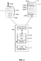
- FIG. 2 illustrates examples of UEs in accordance with embodiments of the invention.
- UE 200A is illustrated as a calling telephone and UE 200B is illustrated as a touchscreen device (e.g., a smart phone, a tablet computer, etc.).
- an external casing of UE 200A is configured with an antenna 205A, display 210A, at least one button 215A (e.g., a PTT button, a power button, a volume control button, etc.) and a keypad 220A among other components, as is known in the art.
- button 215A e.g., a PTT button, a power button, a volume control button, etc.
- an external casing of UE 200B is configured with a touchscreen display 205B, peripheral buttons 210B, 215B, 220B and 225B (e.g., a power control button, a volume or vibrate control button, an airplane mode toggle button, etc.), at least one front-panel button 230B (e.g., a Home button, etc.), among other components, as is known in the art.
- peripheral buttons 210B, 215B, 220B and 225B e.g., a power control button, a volume or vibrate control button, an airplane mode toggle button, etc.
- at least one front-panel button 230B e.g., a Home button, etc.
- the UE 200B can include one or more external antennas and/or one or more integrated antennas that are built into the external casing of UE 200B, including but not limited to WiFi antennas, cellular antennas, satellite position system (SPS) antennas (e.g., global positioning system (GPS) antennas), and so on.
- WiFi antennas e.g., WiFi
- cellular antennas e.g., cellular antennas
- satellite position system (SPS) antennas e.g., global positioning system (GPS) antennas
- GPS global positioning system
- the platform 202 can receive and execute software applications, data and/or commands transmitted from the RAN 120 that may ultimately come from the core network 140, the Internet 175 and/or other remote servers and networks (e.g., application server 170, web URLs, etc.).
- the platform 202 can also independently execute locally stored applications without RAN interaction.
- the platform 202 can include a transceiver 206 operably coupled to an application specific integrated circuit (ASIC) 208, or other processor, microprocessor, logic circuit, or other data processing device.
- ASIC application specific integrated circuit
- the ASIC 208 or other processor executes the application programming interface (API) 210 layer that interfaces with any resident programs in the memory 212 of the wireless device.
- the memory 212 can be comprised of read-only memory (ROM), random-access memory (RAM), electrically erasable programmable ROM (EEPROM), flash cards, or any memory common to computer platforms.
- the platform 202 also can include a local database 214 that can store applications not actively used in memory 212, as well as other data.
- the local database 214 is typically a flash memory cell, but can be any secondary storage device as known in the art, such as magnetic media, EEPROM, optical media, tape, soft or hard disk, or the like.
- an embodiment of the invention can include a UE (e.g., UE 200A, 200B, etc.) including the ability to perform the functions described herein.
- a UE e.g., UE 200A, 200B, etc.
- the various logic elements can be embodied in discrete elements, software modules executed on a processor or any combination of software and hardware to achieve the functionality disclosed herein.
- ASIC 208, memory 212, API 210 and local database 214 may all be used cooperatively to load, store and execute the various functions disclosed herein and thus the logic to perform these functions may be distributed over various elements.
- the functionality could be incorporated into one discrete component. Therefore, the features of the UEs 200A and 200B in FIG. 2 are to be considered merely illustrative and the invention is not limited to the illustrated features or arrangement.
- the wireless communication between the UEs 200A and/or 200B and the RAN 120 can be based on different technologies, such as CDMA, W-CDMA, time division multiple access (TDMA), frequency division multiple access (FDMA), Orthogonal Frequency Division Multiplexing (OFDM), GSM, or other protocols that may be used in a wireless communications network or a data communications network.
- CDMA Code Division Multiple Access
- W-CDMA time division multiple access
- FDMA frequency division multiple access
- OFDM Orthogonal Frequency Division Multiplexing
- GSM Global System for Mobile communications
- voice transmission and/or data can be transmitted to the UEs from the RAN using a variety of networks and configurations. Accordingly, the illustrations provided herein are not intended to limit the embodiments of the invention and are merely to aid in the description of aspects of embodiments of the invention.
- FIG. 3 illustrates a communication device 300 that includes logic configured to perform functionality.
- the communication device 300 can correspond to any of the above-noted communication devices, including but not limited to UEs 200A or 200B, any component of the RAN 120, any component of the core network 140, any components coupled with the core network 140 and/or the Internet 175 (e.g., the application server 170), and so on.
- communication device 300 can correspond to any electronic device that is configured to communicate with (or facilitate communication with) one or more other entities over the wireless communications system 100 of FIG. 1 .
- the communication device 300 includes logic configured to receive and/or transmit information 305.
- the logic configured to receive and/or transmit information 305 can include a wireless communications interface (e.g., Bluetooth, WiFi, 2G, CDMA, W-CDMA, 3G, 4G, LTE, etc.) such as a wireless transceiver and associated hardware (e.g., an RF antenna, a MODEM, a modulator and/or demodulator, etc.).
- a wireless communications interface e.g., Bluetooth, WiFi, 2G, CDMA, W-CDMA, 3G, 4G, LTE, etc.
- a wireless transceiver and associated hardware e.g., an RF antenna, a MODEM, a modulator and/or demodulator, etc.
- the logic configured to receive and/or transmit information 305 can correspond to a wired communications interface (e.g., a serial connection, a USB or Firewire connection, an Ethernet connection through which the Internet 175 can be accessed, etc.).
- a wired communications interface e.g., a serial connection, a USB or Firewire connection, an Ethernet connection through which the Internet 175 can be accessed, etc.
- the logic configured to receive and/or transmit information 305 can correspond to an Ethernet card, in an example, that connects the network-based server to other communication entities via an Ethernet protocol.
- the logic configured to receive and/or transmit information 305 can include sensory or measurement hardware by which the communication device 300 can monitor its local environment (e.g., an accelerometer, a temperature sensor, a light sensor, an antenna for monitoring local RF signals, etc.).
- the logic configured to receive and/or transmit information 305 can include logic configured to receive first sensor data having a first timestamp from a first sensor having a first bandwidth and logic configured to receive second sensor data having a second timestamp from a second sensor having a second bandwidth.
- the logic configured to receive and/or transmit information 305 can also include software that, when executed, permits the associated hardware of the logic configured to receive and/or transmit information 305 to perform its reception and/or transmission function(s).
- the logic configured to receive and/or transmit information 305 does not correspond to software alone, and the logic configured to receive and/or transmit information 305 relies at least in part upon hardware to achieve its functionality.
- the communication device 300 further includes logic configured to process information 310.
- the logic configured to process information 310 can include at least a processor.
- Example implementations of the type of processing that can be performed by the logic configured to process information 310 includes but is not limited to performing determinations, establishing connections, making selections between different information options, performing evaluations related to data, interacting with sensors coupled to the communication device 300 to perform measurement operations, converting information from one format to another (e.g., between different protocols such as .wmv to .avi, etc.), and so on.
- the logic configured to process information 310 can include logic configured to compensate for a first time delay of a first sensor and a second time delay of a second sensor and logic configured to match a frequency of the first bandwidth to a frequency of the second bandwidth.
- the processor included in the logic configured to process information 310 can correspond to a general purpose processor, a digital signal processor (DSP), an ASIC, a field programmable gate array (FPGA) or other programmable logic device, discrete gate or transistor logic, discrete hardware components, or any combination thereof designed to perform the functions described herein.
- a general purpose processor may be a microprocessor, but in the alternative, the processor may be any conventional processor, controller, microcontroller, or state machine.
- a processor may also be implemented as a combination of computing devices, e.g., a combination of a DSP and a microprocessor, a plurality of microprocessors, one or more microprocessors in conjunction with a DSP core, or any other such configuration.
- the logic configured to process information 310 can also include software that, when executed, permits the associated hardware of the logic configured to process information 310 to perform its processing function(s). However, the logic configured to process information 310 does not correspond to software alone, and the logic configured to process information 310 relies at least in part upon hardware to achieve its functionality.
- the communication device 300 further includes logic configured to store information 315.
- the logic configured to store information 315 can include at least a non-transitory memory and associated hardware (e.g., a memory controller, etc.).
- the non-transitory memory included in the logic configured to store information 315 can correspond to RAM, flash memory, ROM, erasable programmable ROM (EPROM), EEPROM, registers, hard disk, a removable disk, a CD-ROM, or any other form of storage medium known in the art.
- the logic configured to store information 315 can also include software that, when executed, permits the associated hardware of the logic configured to store information 315 to perform its storage function(s). However, the logic configured to store information 315 does not correspond to software alone, and the logic configured to store information 315 relies at least in part upon hardware to achieve its functionality.
- the communication device 300 further optionally includes logic configured to present information 320.
- the logic configured to present information 320 can include at least an output device and associated hardware.
- the output device can include a video output device (e.g., a display screen, a port that can carry video information such as USB (Universal Serial Bus), HDMI (High-Definition Multimedia Interface), etc.), an audio output device (e.g., speakers, a port that can carry audio information such as a microphone jack, USB, HDMI, etc.), a vibration device and/or any other device by which information can be formatted for output or actually outputted by a user or operator of the communication device 300.
- a video output device e.g., a display screen, a port that can carry video information such as USB (Universal Serial Bus), HDMI (High-Definition Multimedia Interface), etc.
- an audio output device e.g., speakers, a port that can carry audio information such as a microphone jack, USB, HDMI, etc.
- a vibration device e.
- the logic configured to present information 320 can include the display 210A of UE 200A or the touchscreen display 205B of UE 200B.
- the logic configured to present information 320 can be omitted for certain communication devices, such as network communication devices that do not have a local user (e.g., network switches or routers, remote servers, etc.).
- the logic configured to present information 320 can also include software that, when executed, permits the associated hardware of the logic configured to present information 320 to perform its presentation function(s).
- the logic configured to present information 320 does not correspond to software alone, and the logic configured to present information 320 relies at least in part upon hardware to achieve its functionality.
- the communication device 300 further optionally includes logic configured to receive local user input 325.
- the logic configured to receive local user input 325 can include at least a user input device and associated hardware.
- the user input device can include buttons, a touchscreen display, a keyboard, a camera, an audio input device (e.g., a microphone or a port that can carry audio information such as a microphone jack, etc.), and/or any other device by which information can be received from a user or operator of the communication device 300.
- the communication device 300 corresponds to UE 200A or UE 200B as shown in FIG.
- the logic configured to receive local user input 325 can include the keypad 220A, any of the buttons 215A or 210B through 225B, the touchscreen display 205B, etc.
- the logic configured to receive local user input 325 can be omitted for certain communication devices, such as network communication devices that do not have a local user (e.g., network switches or routers, remote servers, etc.).
- the logic configured to receive local user input 325 can also include software that, when executed, permits the associated hardware of the logic configured to receive local user input 325 to perform its input reception function(s). However, the logic configured to receive local user input 325 does not correspond to software alone, and the logic configured to receive local user input 325 relies at least in part upon hardware to achieve its functionality.
- any software used to facilitate the functionality of the configured logics of 305 through 325 can be stored in the non-transitory memory associated with the logic configured to store information 315, such that the configured logics of 305 through 325 each performs their functionality (i.e., in this case, software execution) based in part upon the operation of software stored by the logic configured to store information 315.
- hardware that is directly associated with one of the configured logics can be borrowed or used by other configured logics from time to time.
- the processor of the logic configured to process information 310 can format data into an appropriate format before being transmitted by the logic configured to receive and/or transmit information 305, such that the logic configured to receive and/or transmit information 305 performs its functionality (i.e., in this case, transmission of data) based in part upon the operation of hardware (i.e., the processor) associated with the logic configured to process information 310.
- logic configured to as used throughout this disclosure is intended to invoke an embodiment that is at least partially implemented with hardware, and is not intended to map to software-only implementations that are independent of hardware.
- the configured logic or “logic configured to” in the various blocks are not limited to specific logic gates or elements, but generally refer to the ability to perform the functionality described herein (either via hardware or a combination of hardware and software).
- the configured logics or “logic configured to” as illustrated in the various blocks are not necessarily implemented as logic gates or logic elements despite sharing the word “logic.” Other interactions or cooperation between the logic in the various blocks will become clear to one of ordinary skill in the art from a review of the embodiments described below in more detail.
- Mobile devices such as cell phones, personal digital assistants (PDAs), tablet computers, etc., frequently contain inertial sensors, such as accelerometers and gyroscopes.
- the mobile device can determine its acceleration and/or rotation, for example, by sampling the data output by the accelerometer and/or gyroscope, respectively, at a given sampling rate.
- Inertial sensors are typically implemented as low-cost microelectromechanical systems (MEMS) inertial sensors.
- MEMS microelectromechanical systems
- MEMS inertial sensors may have lower bandwidth (i.e. the difference between the upper and lower frequencies) than the Nyquist frequency (i.e., half the sampling rate/frequency) that corresponds to the sampling rate.
- the bandwidth of the accelerometer may differ from the bandwidth of the gyroscope even if they are used in the same mobile device.
- different frequency filters may be applied to accelerometers than to gyroscopes. This has at least two effects: (1) the frequency content and (2) the signal group delay are different in the accelerometer and the gyroscope.
- this frequency and time delay mismatch can negatively affect performance. Such a mismatch causes a measurable performance degradation in inertial systems.
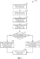
- FIG. 4 illustrates various sources of time delay inside an exemplary sensor 400.
- Sensor 400 may be any sensor that senses physical events and/or environmental conditions, including but not limited to an inertial sensor, such as an accelerometer or a gyroscope.
- a physical event occurs.
- the physical event could be movement of a mobile device in which the sensor 400 is housed.
- the movement may be an acceleration, a vibration, a rotation, or the like.
- a sensing element 420 senses the physical event 410 and transmits the data in analog form to an analog-to-digital converter (ADC) 430.
- the ADC 430 converts the analog signal received from the sensing element 420 to a digital signal and outputs this digital signal to a filtering element 440.
- This conversion introduces a first time delay ⁇ t 1 .
- the filtering element 440 samples the digital signal at a given sampling rate and sends the filtered data to a decimation element 450.
- This filtering introduces a second time delay At 2 .
- the decimation element 450 processes the filtered data received from the filtering element 440 to reduce the sampling rate. This introduces a third time delay ⁇ t 3 .
- the decimation element 450 sends the decimated data to filtering element 460.
- Filtering element 460 filters the decimated data and sends it to output register 470. This filtering introduces a fourth time delay ⁇ t 4 .
- the data collection and time stamping mechanism 480 reads the processed data from the output register 470 and assigns a timestamp to it.
- time delay there is a time delay between the time the physical event occurs and the time at which the data output from the sensor is time stamped. This delay occurs even if the time stamping mechanism is perfect, i.e. introduces no further delay.
- the time delay can be determined from the design of the sensor. For example, the manufacturer of the sensor may provide this information.
- the time delay can also be determined by testing the sensor, such as by comparing the time a sensed event is output to the known time that the event occurred.
- FIG. 5 is an exemplary illustration of the error caused by a time offset when two signals are multiplied.
- the output of a sensor A is shown in graph 510 and the output of a sensor B is shown in graph 520.
- the multiplied signal is shown in graph 530.
- the output of both sensors A and B are synchronized with respect to time, as shown by the simultaneous spike at time 35.
- the output of sensor A is again shown in graph 540.
- Graph 550 shows the output of sensor B but with a smaller time delay, designated "C.” In this case, multiplying A and C does not equal the simultaneous spike in graph 560 as it did in graph 530. Rather, the sensed events appear to be separate events. This degrades the accuracy of the application using the sensor data.
- the relative time delay difference between the two sensors can be determined.
- the relative time delay is approximately five.
- the relative time delay can then be used to synchronize the timestamps of the two sensors. For example, the relative time delay can be added to the timestamp of the faster sensor or subtracted from the timestamp of the slower sensor so that the timestamps of the two sensors match.
- the relative time delay can be determined by testing the sensors, such as by comparing the timestamps output by the sensors after they sense the same event.
- the synchronization of the sensors is more important than the accuracy of the sensors. Accordingly, the sensors can be synchronized using the relative time delay between the sensors instead of the absolute time delay of each sensor.
- the various embodiments presented herein can match the bandwidths and/or the signal time delay of two or more sensors being used by an application.
- the bandwidths of the sensors are determined and additional filtering is applied to match the frequency characteristics of the sensor data.
- the time delays are measured or otherwise determined, and an additional time delay is introduced on the appropriate sensor to bring the delays to the same value.
- the frequency matching and the time delay matching can be applied separately or in combination.
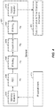
- FIG. 6 illustrates an exemplary embodiment to compensate for different bandwidths and time delays between two sensors 620 and 622.
- FIG. 6 illustrates two sensors, there could be any number of different co-located sensors. That the sensors are co-located means that the sensors are on the same device. The sensors need not be adjacent, they merely need to sense the same physical event. The sensors can be the same type of sensor or different types of sensors.
- Sensors 620 and 622 detect physical event 610.
- the data collection and time stamping mechanism 630 reads the sensor data generated by sensors 620 and 622 and assigns timestamps to the data.
- the time stamped data is then passed to timestamp correction elements 640 and 642.
- Timestamp correction element 640 determines or is provided the time delay for sensor 620. As discussed above with reference to FIG. 4 , the time delay is the time difference between the value of the timestamp assigned to the sensor data by the data collection and time stamping mechanism 630 and the time at which the physical event was actually detected. The timestamp correction element 640 generates a corrected timestamp, or modifies the assigned timestamp, by adding the time delay to the value of the assigned timestamp.
- Timestamp correction element 642 performs a similar process for sensor 622. If there are other sensors being used by the application, corresponding timestamp correction elements perform a similar process for each of them.
- the sensor data with the corrected timestamps are then passed to compensating filters 650 and 652, which compensate for different sampling frequencies in the sensors 620 and 622, respectively. If the frequency of the bandwidth of sensor 620 is greater than the frequency of the bandwidth of sensor 622, then compensating filter 650 filters the frequency of the bandwidth of sensor 620 to match the frequency of the bandwidth of sensor 622. If, however, the frequency of the bandwidth of sensor 622 is greater than the frequency of the bandwidth of sensor 620, then the compensating filter 652 filters the frequency of the bandwidth of sensor 622 to match the frequency of the bandwidth of sensor 620. If the frequencies of the bandwidths are the same, then no compensation needs to be performed.
- the sensor data need not be passed to compensating filters 650 and 652 after passing through timestamp correction elements 640 and 642, as illustrated in FIG. 6 .
- timestamp correction elements 640 and 642 As discussed above, in some embodiments, only time delays may be matched.
- the sensor data can pass through compensating filters 650 and 652 after being detected by sensors 620 and 622, or after passing through the data collection and time stamping mechanism 630.
- corresponding compensating filters perform a similar process for each of them. In that case also, the lowest bandwidth frequency is determined and the higher bandwidth frequencies are filtered to match the lowest frequency.
- the filtered sensor data is then passed on for additional processing 660 by the application using sensors 620 and 622.
- the data from sensors 620 and 622 is now matched with respect to time and bandwidth frequency.
- FIG. 6 illustrates timestamp correction elements 640 and 642 as separate components/modules, they may be embodied as a single component/module that receives data for each sensor from the data collection and time stamping mechanism 630.
- FIG. 6 illustrates compensating filters 650 and 652 as separate components/modules, they may be embodied as a single component/module that receives data for each sensor from the timestamp correction element(s).
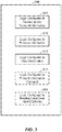
- FIG. 7 illustrates an exemplary flow 700 of an embodiment.
- the flow 700 may be performed by an application using sensor data, by an ASIC or other processor, or by a combination of both.
- sensor data from a first sensor is received.
- the sensor may be an inertial sensor, such as an accelerometer or a gyroscope.
- sensor data from a second sensor is received.
- the second sensor may also be an inertial sensor, such as an accelerometer or a gyroscope.
- a corrected timestamp for the first sensor data is generated.
- a corrected timestamp for the second sensor data is generated.
- the application and/or processor determines whether or not the frequency of the bandwidth of the first sensor is greater than the frequency of the bandwidth of the second sensor. If it is, then at 760, the frequency of the first bandwidth is filtered to match the frequency of the second bandwidth. If, however, the frequency of the second bandwidth is greater than the frequency of the first bandwidth, then at 770, the frequency of the second bandwidth is filtered to match the frequency of the first bandwidth.
- the matched sensor data is processed. For example, if the first and second sensors are an accelerometer and a gyroscope and the application is a navigational application, the application processes the matched sensor data to provide more accurate navigational guidance.
- DSP digital signal processor
- ASIC application specific integrated circuit
- FPGA field programmable gate array
- a general purpose processor may be a microprocessor, but in the alternative, the processor may be any conventional processor, controller, microcontroller, or state machine.
- a processor may also be implemented as a combination of computing devices, e.g., a combination of a DSP and a microprocessor, a plurality of microprocessors, one or more microprocessors in conjunction with a DSP core, or any other such configuration.
- a software module may reside in RAM memory, flash memory, ROM memory, EPROM memory, EEPROM memory, registers, hard disk, a removable disk, a CD-ROM, or any other form of storage medium known in the art.
- An exemplary storage medium is coupled to the processor such that the processor can read information from, and write information to, the storage medium.
- the storage medium may be integral to the processor.
- the processor and the storage medium may reside in an ASIC.
- the ASIC may reside in a user terminal (e.g., UE).
- the processor and the storage medium may reside as discrete components in a user terminal.
- the functions described may be implemented in hardware, software, firmware, or any combination thereof. If implemented in software, the functions may be stored on or transmitted over as one or more instructions or code on a computer-readable medium.
- Computer-readable media includes both computer storage media and communication media including any medium that facilitates transfer of a computer program from one place to another.
- a storage media may be any available media that can be accessed by a computer.
- such computer-readable media can comprise RAM, ROM, EEPROM, CD-ROM or other optical disk storage, magnetic disk storage or other magnetic storage devices, or any other medium that can be used to carry or store desired program code in the form of instructions or data structures and that can be accessed by a computer.
- any connection is properly termed a computer-readable medium.
- the software is transmitted from a website, server, or other remote source using a coaxial cable, fiber optic cable, twisted pair, digital subscriber line (DSL), or wireless technologies such as infrared, radio, and microwave
- the coaxial cable, fiber optic cable, twisted pair, DSL, or wireless technologies such as infrared, radio, and microwave are included in the definition of medium.
- Disk and disc includes compact disc (CD), laser disc, optical disc, digital versatile disc (DVD), floppy disk and blu-ray disc where disks usually reproduce data magnetically, while discs reproduce data optically with lasers. Combinations of the above should also be included within the scope of computer-readable media.
Landscapes
- Engineering & Computer Science (AREA)
- Physics & Mathematics (AREA)
- General Physics & Mathematics (AREA)
- Health & Medical Sciences (AREA)
- Computing Systems (AREA)
- General Health & Medical Sciences (AREA)
- Medical Informatics (AREA)
- Computer Networks & Wireless Communication (AREA)
- Signal Processing (AREA)
- Telephone Function (AREA)
- Mobile Radio Communication Systems (AREA)
- Gyroscopes (AREA)
Applications Claiming Priority (2)
| Application Number | Priority Date | Filing Date | Title |
|---|---|---|---|
| US13/792,944 US20140257730A1 (en) | 2013-03-11 | 2013-03-11 | Bandwidth and time delay matching for inertial sensors |
| PCT/US2014/021628 WO2014197019A1 (en) | 2013-03-11 | 2014-03-07 | Bandwidth and time delay matching for inertial sensors |
Publications (2)
| Publication Number | Publication Date |
|---|---|
| EP2974235A1 EP2974235A1 (en) | 2016-01-20 |
| EP2974235B1 true EP2974235B1 (en) | 2018-01-31 |
Family
ID=51488885
Family Applications (1)
| Application Number | Title | Priority Date | Filing Date |
|---|---|---|---|
| EP14771642.7A Not-in-force EP2974235B1 (en) | 2013-03-11 | 2014-03-07 | Bandwidth and time delay matching for inertial sensors |
Country Status (6)
Families Citing this family (18)
| Publication number | Priority date | Publication date | Assignee | Title |
|---|---|---|---|---|
| CN105308537A (zh) * | 2013-05-02 | 2016-02-03 | (株)未来百乐 | 匹配多个装置的方法、以及使所述匹配成为可能的装置及服务器系统 |
| US9686051B2 (en) * | 2013-12-27 | 2017-06-20 | Lord Corporation | Systems, methods, and computer readable media for lossless data transmission in a wireless network |
| US10180340B2 (en) * | 2014-10-09 | 2019-01-15 | Invensense, Inc. | System and method for MEMS sensor system synchronization |
| DE102015108859B4 (de) * | 2015-06-03 | 2018-12-27 | Cortec Gmbh | Verfahren und System zum Verarbeiten von Datenströmen |
| US9977839B2 (en) | 2015-06-05 | 2018-05-22 | Qualcomm Incorporated | Improving accuracy of time of event determination at sensor device |
| KR102742349B1 (ko) * | 2015-11-10 | 2024-12-13 | 소니 세미컨덕터 솔루션즈 가부시키가이샤 | 전자장치, 제어 회로, 및, 전자장치의 제어 방법 |
| US10345339B2 (en) | 2015-12-09 | 2019-07-09 | Tektronix, Inc. | Group delay based averaging |
| WO2017108374A1 (en) * | 2015-12-22 | 2017-06-29 | Philips Lighting Holding B.V. | Sensor system. |
| US10490056B2 (en) * | 2016-11-10 | 2019-11-26 | Bently Nevada, Llc | Equipment monitoring systems and devices |
| CN106597021B (zh) * | 2016-12-23 | 2019-03-01 | 北京化工大学 | 一种基于调制函数的加速度计测量通道延迟时间估计方法 |
| CN107144343A (zh) * | 2017-07-10 | 2017-09-08 | 薛天 | 低频振动位移传感器组网方法、系统及装置 |
| CN109189049B (zh) * | 2018-10-15 | 2020-05-26 | 浙江工业大学 | 一种适用于网络化控制系统的主动时延补偿方法 |
| CN109540192B (zh) * | 2018-10-23 | 2020-01-10 | 北京诺亦腾科技有限公司 | 一种动作捕捉系统的时间延迟测量方法、装置及存储介质 |
| CN109883426B (zh) * | 2019-03-08 | 2022-01-14 | 哈尔滨工程大学 | 基于因子图的动态分配与校正多源信息融合方法 |
| CN111856468B (zh) * | 2019-04-16 | 2024-12-17 | 斑马智行网络(香港)有限公司 | 检测方法、装置、设备、系统及存储介质 |
| WO2021147036A1 (en) * | 2020-01-22 | 2021-07-29 | Abb Schweiz Ag | System and method for controlling the robot, electronic device and computer readable medium |
| CN112254736A (zh) * | 2020-09-15 | 2021-01-22 | 株洲菲斯罗克光电技术有限公司 | 一种惯导与里程计组合导航的时延误差的补偿方法及系统 |
| US12170573B2 (en) * | 2022-10-04 | 2024-12-17 | Cisco Technology, Inc. | Sensor measurement timestamp differences |
Citations (1)
| Publication number | Priority date | Publication date | Assignee | Title |
|---|---|---|---|---|
| US20120290266A1 (en) * | 2011-05-13 | 2012-11-15 | Fujitsu Limited | Data Aggregation Platform |
Family Cites Families (18)
| Publication number | Priority date | Publication date | Assignee | Title |
|---|---|---|---|---|
| US6404204B1 (en) * | 2000-05-01 | 2002-06-11 | ARETé ASSOCIATES | Sensor and sensor system for liquid conductivity, temperature and depth |
| CN1361431A (zh) * | 2000-12-23 | 2002-07-31 | 林清芳 | 完全整合式导航定位方法和系统 |
| US6792118B2 (en) * | 2001-11-14 | 2004-09-14 | Applied Neurosystems Corporation | Computation of multi-sensor time delays |
| US20050165575A1 (en) * | 2003-09-23 | 2005-07-28 | Jacob Mettes | Automated regression analysis and its applications such as water analysis |
| JP4650248B2 (ja) * | 2005-12-09 | 2011-03-16 | 株式会社デンソー | 車両用ネットワークシステム及びネットワークノード |
| JP5215195B2 (ja) * | 2006-03-15 | 2013-06-19 | クゥアルコム・インコーポレイテッド | センサベースのオリエンテーションシステム |
| US7937232B1 (en) * | 2006-07-06 | 2011-05-03 | Pivotal Systems Corporation | Data timestamp management |
| WO2009093891A1 (en) * | 2008-01-25 | 2009-07-30 | Mobihealth B.V. | Mobile monitoring system and method |
| US8589720B2 (en) * | 2008-04-15 | 2013-11-19 | Qualcomm Incorporated | Synchronizing timing mismatch by data insertion |
| US7792040B2 (en) * | 2008-07-30 | 2010-09-07 | Yahoo! Inc. | Bandwidth and cost management for ad hoc networks |
| US8647287B2 (en) * | 2008-12-07 | 2014-02-11 | Andrew Greenberg | Wireless synchronized movement monitoring apparatus and system |
| US10054444B2 (en) * | 2009-05-29 | 2018-08-21 | Qualcomm Incorporated | Method and apparatus for accurate acquisition of inertial sensor data |
| US8254412B2 (en) * | 2010-01-25 | 2012-08-28 | Cisco Technology, Inc. | Implementing priority based dynamic bandwidth adjustments |
| US8279896B2 (en) * | 2010-03-02 | 2012-10-02 | Hewlett-Packard Development Company, L.P. | Synchronization in a wireless node |
| EP2619594A4 (en) * | 2010-09-20 | 2015-09-02 | Fairchild Semiconductor | MODE TUNING CIRCUIT FOR AN INERTIAL SENSOR |
| JP5690176B2 (ja) * | 2011-03-11 | 2015-03-25 | 日立オートモティブシステムズ株式会社 | 慣性センサ |
| US9141759B2 (en) * | 2011-03-31 | 2015-09-22 | Adidas Ag | Group performance monitoring system and method |
| US20140257729A1 (en) * | 2013-03-07 | 2014-09-11 | Eric A. Wolf | Time synchronized redundant sensors |
-
2013
- 2013-03-11 US US13/792,944 patent/US20140257730A1/en not_active Abandoned
-
2014
- 2014-03-07 WO PCT/US2014/021628 patent/WO2014197019A1/en active Application Filing
- 2014-03-07 JP JP2016500798A patent/JP6411447B2/ja not_active Expired - Fee Related
- 2014-03-07 EP EP14771642.7A patent/EP2974235B1/en not_active Not-in-force
- 2014-03-07 KR KR1020157027147A patent/KR20150130345A/ko not_active Withdrawn
- 2014-03-07 CN CN201480013255.XA patent/CN105027536B/zh not_active Expired - Fee Related
Patent Citations (1)
| Publication number | Priority date | Publication date | Assignee | Title |
|---|---|---|---|---|
| US20120290266A1 (en) * | 2011-05-13 | 2012-11-15 | Fujitsu Limited | Data Aggregation Platform |
Also Published As
| Publication number | Publication date |
|---|---|
| CN105027536B (zh) | 2019-04-23 |
| CN105027536A (zh) | 2015-11-04 |
| JP6411447B2 (ja) | 2018-10-24 |
| JP2016519282A (ja) | 2016-06-30 |
| US20140257730A1 (en) | 2014-09-11 |
| KR20150130345A (ko) | 2015-11-23 |
| EP2974235A1 (en) | 2016-01-20 |
| WO2014197019A1 (en) | 2014-12-11 |
Similar Documents
| Publication | Publication Date | Title |
|---|---|---|
| EP2974235B1 (en) | Bandwidth and time delay matching for inertial sensors | |
| CN116112110A (zh) | 用于补偿时钟漂移引起的时间同步中的错误的技术 | |
| CN108702590B (zh) | 用于无限测距会话的技术 | |
| US20140114568A1 (en) | Changing a position determination scheme used by a user equipment during a transition between indoor and outdoor spaces relative to an enclosed environment | |
| US9241353B2 (en) | Communications between a mobile device and an access point device | |
| US20140274111A1 (en) | Inter-device transfer of accurate location information | |
| TWI701913B (zh) | 用於表示誤差之方法及系統 | |
| WO2013102324A1 (zh) | 时间校准方法及装置 | |
| US20200394926A1 (en) | Methods and apparatuses for updating uav status in uas ecosystem | |
| CN103596261B (zh) | 一种车辆检测系统的时钟同步方法 | |
| WO2017045474A1 (zh) | 报文解析的方法及装置 | |
| US20250031174A1 (en) | Method for Verifying Location of Terminal, Terminal, and Network Side Device | |
| WO2016065642A1 (zh) | 一种同步装置及方法 | |
| US20150043553A1 (en) | Configuring a secure network infrastructure device | |
| US10281485B2 (en) | Multi-path signal processing for microelectromechanical systems (MEMS) sensors | |
| KR101244915B1 (ko) | 매체접근제어 계층에서 애플리케이션 계층에 동기화 정보를제공하는 방법 및 이를 위한 장치 | |
| KR101203529B1 (ko) | 네트워크에서 단말들간의 애플리케이션을 동기화하는 방법및 장치 | |
| KR20170064990A (ko) | 통신 링크 메커니즘을 갖는 컴퓨팅 시스템 | |
| EP3420747B1 (en) | Method and wireless station for a ranging protocol | |
| US20200092893A1 (en) | Distance measurements based on round-trip phase measurements | |
| WO2024168625A1 (zh) | 信息处理方法、系统及装置、通信设备及存储介质 |
Legal Events
| Date | Code | Title | Description |
|---|---|---|---|
| PUAI | Public reference made under article 153(3) epc to a published international application that has entered the european phase |
Free format text: ORIGINAL CODE: 0009012 |
|
| 17P | Request for examination filed |
Effective date: 20150722 |
|
| AK | Designated contracting states |
Kind code of ref document: A1 Designated state(s): AL AT BE BG CH CY CZ DE DK EE ES FI FR GB GR HR HU IE IS IT LI LT LU LV MC MK MT NL NO PL PT RO RS SE SI SK SM TR |
|
| AX | Request for extension of the european patent |
Extension state: BA ME |
|
| DAX | Request for extension of the european patent (deleted) | ||
| 17Q | First examination report despatched |
Effective date: 20161005 |
|
| GRAP | Despatch of communication of intention to grant a patent |
Free format text: ORIGINAL CODE: EPIDOSNIGR1 |
|
| INTG | Intention to grant announced |
Effective date: 20170919 |
|
| GRAS | Grant fee paid |
Free format text: ORIGINAL CODE: EPIDOSNIGR3 |
|
| GRAA | (expected) grant |
Free format text: ORIGINAL CODE: 0009210 |
|
| AK | Designated contracting states |
Kind code of ref document: B1 Designated state(s): AL AT BE BG CH CY CZ DE DK EE ES FI FR GB GR HR HU IE IS IT LI LT LU LV MC MK MT NL NO PL PT RO RS SE SI SK SM TR |
|
| REG | Reference to a national code |
Ref country code: GB Ref legal event code: FG4D Ref country code: CH Ref legal event code: EP |
|
| REG | Reference to a national code |
Ref country code: AT Ref legal event code: REF Ref document number: 968299 Country of ref document: AT Kind code of ref document: T Effective date: 20180215 |
|
| REG | Reference to a national code |
Ref country code: IE Ref legal event code: FG4D |
|
| REG | Reference to a national code |
Ref country code: DE Ref legal event code: R096 Ref document number: 602014020477 Country of ref document: DE |
|
| REG | Reference to a national code |
Ref country code: FR Ref legal event code: PLFP Year of fee payment: 5 |
|
| PGFP | Annual fee paid to national office [announced via postgrant information from national office to epo] |
Ref country code: GB Payment date: 20180309 Year of fee payment: 5 |
|
| PGFP | Annual fee paid to national office [announced via postgrant information from national office to epo] |
Ref country code: FR Payment date: 20180309 Year of fee payment: 5 |
|
| REG | Reference to a national code |
Ref country code: NL Ref legal event code: MP Effective date: 20180131 |
|
| REG | Reference to a national code |
Ref country code: LT Ref legal event code: MG4D |
|
| REG | Reference to a national code |
Ref country code: AT Ref legal event code: MK05 Ref document number: 968299 Country of ref document: AT Kind code of ref document: T Effective date: 20180131 |
|
| PG25 | Lapsed in a contracting state [announced via postgrant information from national office to epo] |
Ref country code: HR Free format text: LAPSE BECAUSE OF FAILURE TO SUBMIT A TRANSLATION OF THE DESCRIPTION OR TO PAY THE FEE WITHIN THE PRESCRIBED TIME-LIMIT Effective date: 20180131 Ref country code: NL Free format text: LAPSE BECAUSE OF FAILURE TO SUBMIT A TRANSLATION OF THE DESCRIPTION OR TO PAY THE FEE WITHIN THE PRESCRIBED TIME-LIMIT Effective date: 20180131 Ref country code: LT Free format text: LAPSE BECAUSE OF FAILURE TO SUBMIT A TRANSLATION OF THE DESCRIPTION OR TO PAY THE FEE WITHIN THE PRESCRIBED TIME-LIMIT Effective date: 20180131 Ref country code: FI Free format text: LAPSE BECAUSE OF FAILURE TO SUBMIT A TRANSLATION OF THE DESCRIPTION OR TO PAY THE FEE WITHIN THE PRESCRIBED TIME-LIMIT Effective date: 20180131 Ref country code: NO Free format text: LAPSE BECAUSE OF FAILURE TO SUBMIT A TRANSLATION OF THE DESCRIPTION OR TO PAY THE FEE WITHIN THE PRESCRIBED TIME-LIMIT Effective date: 20180430 Ref country code: ES Free format text: LAPSE BECAUSE OF FAILURE TO SUBMIT A TRANSLATION OF THE DESCRIPTION OR TO PAY THE FEE WITHIN THE PRESCRIBED TIME-LIMIT Effective date: 20180131 |
|
| PG25 | Lapsed in a contracting state [announced via postgrant information from national office to epo] |
Ref country code: AT Free format text: LAPSE BECAUSE OF FAILURE TO SUBMIT A TRANSLATION OF THE DESCRIPTION OR TO PAY THE FEE WITHIN THE PRESCRIBED TIME-LIMIT Effective date: 20180131 Ref country code: SE Free format text: LAPSE BECAUSE OF FAILURE TO SUBMIT A TRANSLATION OF THE DESCRIPTION OR TO PAY THE FEE WITHIN THE PRESCRIBED TIME-LIMIT Effective date: 20180131 Ref country code: PL Free format text: LAPSE BECAUSE OF FAILURE TO SUBMIT A TRANSLATION OF THE DESCRIPTION OR TO PAY THE FEE WITHIN THE PRESCRIBED TIME-LIMIT Effective date: 20180131 Ref country code: RS Free format text: LAPSE BECAUSE OF FAILURE TO SUBMIT A TRANSLATION OF THE DESCRIPTION OR TO PAY THE FEE WITHIN THE PRESCRIBED TIME-LIMIT Effective date: 20180131 Ref country code: LV Free format text: LAPSE BECAUSE OF FAILURE TO SUBMIT A TRANSLATION OF THE DESCRIPTION OR TO PAY THE FEE WITHIN THE PRESCRIBED TIME-LIMIT Effective date: 20180131 Ref country code: BG Free format text: LAPSE BECAUSE OF FAILURE TO SUBMIT A TRANSLATION OF THE DESCRIPTION OR TO PAY THE FEE WITHIN THE PRESCRIBED TIME-LIMIT Effective date: 20180430 Ref country code: IS Free format text: LAPSE BECAUSE OF FAILURE TO SUBMIT A TRANSLATION OF THE DESCRIPTION OR TO PAY THE FEE WITHIN THE PRESCRIBED TIME-LIMIT Effective date: 20180531 Ref country code: GR Free format text: LAPSE BECAUSE OF FAILURE TO SUBMIT A TRANSLATION OF THE DESCRIPTION OR TO PAY THE FEE WITHIN THE PRESCRIBED TIME-LIMIT Effective date: 20180501 |
|
| PG25 | Lapsed in a contracting state [announced via postgrant information from national office to epo] |
Ref country code: AL Free format text: LAPSE BECAUSE OF FAILURE TO SUBMIT A TRANSLATION OF THE DESCRIPTION OR TO PAY THE FEE WITHIN THE PRESCRIBED TIME-LIMIT Effective date: 20180131 Ref country code: IT Free format text: LAPSE BECAUSE OF FAILURE TO SUBMIT A TRANSLATION OF THE DESCRIPTION OR TO PAY THE FEE WITHIN THE PRESCRIBED TIME-LIMIT Effective date: 20180131 Ref country code: EE Free format text: LAPSE BECAUSE OF FAILURE TO SUBMIT A TRANSLATION OF THE DESCRIPTION OR TO PAY THE FEE WITHIN THE PRESCRIBED TIME-LIMIT Effective date: 20180131 Ref country code: RO Free format text: LAPSE BECAUSE OF FAILURE TO SUBMIT A TRANSLATION OF THE DESCRIPTION OR TO PAY THE FEE WITHIN THE PRESCRIBED TIME-LIMIT Effective date: 20180131 |
|
| REG | Reference to a national code |
Ref country code: CH Ref legal event code: PL |
|
| REG | Reference to a national code |
Ref country code: DE Ref legal event code: R097 Ref document number: 602014020477 Country of ref document: DE |
|
| PG25 | Lapsed in a contracting state [announced via postgrant information from national office to epo] |
Ref country code: SK Free format text: LAPSE BECAUSE OF FAILURE TO SUBMIT A TRANSLATION OF THE DESCRIPTION OR TO PAY THE FEE WITHIN THE PRESCRIBED TIME-LIMIT Effective date: 20180131 Ref country code: CZ Free format text: LAPSE BECAUSE OF FAILURE TO SUBMIT A TRANSLATION OF THE DESCRIPTION OR TO PAY THE FEE WITHIN THE PRESCRIBED TIME-LIMIT Effective date: 20180131 Ref country code: MC Free format text: LAPSE BECAUSE OF FAILURE TO SUBMIT A TRANSLATION OF THE DESCRIPTION OR TO PAY THE FEE WITHIN THE PRESCRIBED TIME-LIMIT Effective date: 20180131 Ref country code: SM Free format text: LAPSE BECAUSE OF FAILURE TO SUBMIT A TRANSLATION OF THE DESCRIPTION OR TO PAY THE FEE WITHIN THE PRESCRIBED TIME-LIMIT Effective date: 20180131 Ref country code: DK Free format text: LAPSE BECAUSE OF FAILURE TO SUBMIT A TRANSLATION OF THE DESCRIPTION OR TO PAY THE FEE WITHIN THE PRESCRIBED TIME-LIMIT Effective date: 20180131 |
|
| PLBE | No opposition filed within time limit |
Free format text: ORIGINAL CODE: 0009261 |
|
| STAA | Information on the status of an ep patent application or granted ep patent |
Free format text: STATUS: NO OPPOSITION FILED WITHIN TIME LIMIT |
|
| REG | Reference to a national code |
Ref country code: BE Ref legal event code: MM Effective date: 20180331 |
|
| REG | Reference to a national code |
Ref country code: IE Ref legal event code: MM4A |
|
| PG25 | Lapsed in a contracting state [announced via postgrant information from national office to epo] |
Ref country code: LU Free format text: LAPSE BECAUSE OF NON-PAYMENT OF DUE FEES Effective date: 20180307 |
|
| 26N | No opposition filed |
Effective date: 20181102 |
|
| PG25 | Lapsed in a contracting state [announced via postgrant information from national office to epo] |
Ref country code: IE Free format text: LAPSE BECAUSE OF NON-PAYMENT OF DUE FEES Effective date: 20180307 |
|
| PG25 | Lapsed in a contracting state [announced via postgrant information from national office to epo] |
Ref country code: SI Free format text: LAPSE BECAUSE OF FAILURE TO SUBMIT A TRANSLATION OF THE DESCRIPTION OR TO PAY THE FEE WITHIN THE PRESCRIBED TIME-LIMIT Effective date: 20180131 Ref country code: CH Free format text: LAPSE BECAUSE OF NON-PAYMENT OF DUE FEES Effective date: 20180331 Ref country code: LI Free format text: LAPSE BECAUSE OF NON-PAYMENT OF DUE FEES Effective date: 20180331 Ref country code: BE Free format text: LAPSE BECAUSE OF NON-PAYMENT OF DUE FEES Effective date: 20180331 |
|
| GBPC | Gb: european patent ceased through non-payment of renewal fee |
Effective date: 20190307 |
|
| PG25 | Lapsed in a contracting state [announced via postgrant information from national office to epo] |
Ref country code: MT Free format text: LAPSE BECAUSE OF NON-PAYMENT OF DUE FEES Effective date: 20180307 Ref country code: GB Free format text: LAPSE BECAUSE OF NON-PAYMENT OF DUE FEES Effective date: 20190307 |
|
| PG25 | Lapsed in a contracting state [announced via postgrant information from national office to epo] |
Ref country code: FR Free format text: LAPSE BECAUSE OF NON-PAYMENT OF DUE FEES Effective date: 20190331 |
|
| PG25 | Lapsed in a contracting state [announced via postgrant information from national office to epo] |
Ref country code: TR Free format text: LAPSE BECAUSE OF FAILURE TO SUBMIT A TRANSLATION OF THE DESCRIPTION OR TO PAY THE FEE WITHIN THE PRESCRIBED TIME-LIMIT Effective date: 20180131 |
|
| PGFP | Annual fee paid to national office [announced via postgrant information from national office to epo] |
Ref country code: DE Payment date: 20200214 Year of fee payment: 7 |
|
| PG25 | Lapsed in a contracting state [announced via postgrant information from national office to epo] |
Ref country code: PT Free format text: LAPSE BECAUSE OF FAILURE TO SUBMIT A TRANSLATION OF THE DESCRIPTION OR TO PAY THE FEE WITHIN THE PRESCRIBED TIME-LIMIT Effective date: 20180131 |
|
| PG25 | Lapsed in a contracting state [announced via postgrant information from national office to epo] |
Ref country code: MK Free format text: LAPSE BECAUSE OF NON-PAYMENT OF DUE FEES Effective date: 20180131 Ref country code: HU Free format text: LAPSE BECAUSE OF FAILURE TO SUBMIT A TRANSLATION OF THE DESCRIPTION OR TO PAY THE FEE WITHIN THE PRESCRIBED TIME-LIMIT; INVALID AB INITIO Effective date: 20140307 Ref country code: CY Free format text: LAPSE BECAUSE OF FAILURE TO SUBMIT A TRANSLATION OF THE DESCRIPTION OR TO PAY THE FEE WITHIN THE PRESCRIBED TIME-LIMIT Effective date: 20180131 |
|
| REG | Reference to a national code |
Ref country code: DE Ref legal event code: R119 Ref document number: 602014020477 Country of ref document: DE |
|
| PG25 | Lapsed in a contracting state [announced via postgrant information from national office to epo] |
Ref country code: DE Free format text: LAPSE BECAUSE OF NON-PAYMENT OF DUE FEES Effective date: 20211001 |