EP2973424B1 - Data display and processing algorithms for 3d imaging systems - Google Patents
Data display and processing algorithms for 3d imaging systems Download PDFInfo
- Publication number
- EP2973424B1 EP2973424B1 EP14764241.7A EP14764241A EP2973424B1 EP 2973424 B1 EP2973424 B1 EP 2973424B1 EP 14764241 A EP14764241 A EP 14764241A EP 2973424 B1 EP2973424 B1 EP 2973424B1
- Authority
- EP
- European Patent Office
- Prior art keywords
- volume
- representation
- imaging
- image data
- region
- Prior art date
- Legal status (The legal status is an assumption and is not a legal conclusion. Google has not performed a legal analysis and makes no representation as to the accuracy of the status listed.)
- Not-in-force
Links
Images


Classifications
-
- G—PHYSICS
- G06—COMPUTING; CALCULATING OR COUNTING
- G06T—IMAGE DATA PROCESSING OR GENERATION, IN GENERAL
- G06T7/00—Image analysis
- G06T7/10—Segmentation; Edge detection
- G06T7/11—Region-based segmentation
-
- G—PHYSICS
- G06—COMPUTING; CALCULATING OR COUNTING
- G06T—IMAGE DATA PROCESSING OR GENERATION, IN GENERAL
- G06T11/00—2D [Two Dimensional] image generation
- G06T11/003—Reconstruction from projections, e.g. tomography
-
- G—PHYSICS
- G06—COMPUTING; CALCULATING OR COUNTING
- G06T—IMAGE DATA PROCESSING OR GENERATION, IN GENERAL
- G06T15/00—3D [Three Dimensional] image rendering
- G06T15/08—Volume rendering
-
- G—PHYSICS
- G06—COMPUTING; CALCULATING OR COUNTING
- G06T—IMAGE DATA PROCESSING OR GENERATION, IN GENERAL
- G06T19/00—Manipulating 3D models or images for computer graphics
-
- G—PHYSICS
- G06—COMPUTING; CALCULATING OR COUNTING
- G06T—IMAGE DATA PROCESSING OR GENERATION, IN GENERAL
- G06T7/00—Image analysis
- G06T7/0002—Inspection of images, e.g. flaw detection
- G06T7/0012—Biomedical image inspection
-
- A—HUMAN NECESSITIES
- A61—MEDICAL OR VETERINARY SCIENCE; HYGIENE
- A61B—DIAGNOSIS; SURGERY; IDENTIFICATION
- A61B8/00—Diagnosis using ultrasonic, sonic or infrasonic waves
- A61B8/46—Ultrasonic, sonic or infrasonic diagnostic devices with special arrangements for interfacing with the operator or the patient
- A61B8/461—Displaying means of special interest
- A61B8/466—Displaying means of special interest adapted to display 3D data
-
- A—HUMAN NECESSITIES
- A61—MEDICAL OR VETERINARY SCIENCE; HYGIENE
- A61B—DIAGNOSIS; SURGERY; IDENTIFICATION
- A61B8/00—Diagnosis using ultrasonic, sonic or infrasonic waves
- A61B8/48—Diagnostic techniques
- A61B8/483—Diagnostic techniques involving the acquisition of a 3D volume of data
-
- G—PHYSICS
- G06—COMPUTING; CALCULATING OR COUNTING
- G06T—IMAGE DATA PROCESSING OR GENERATION, IN GENERAL
- G06T2200/00—Indexing scheme for image data processing or generation, in general
- G06T2200/04—Indexing scheme for image data processing or generation, in general involving 3D image data
-
- G—PHYSICS
- G06—COMPUTING; CALCULATING OR COUNTING
- G06T—IMAGE DATA PROCESSING OR GENERATION, IN GENERAL
- G06T2207/00—Indexing scheme for image analysis or image enhancement
- G06T2207/10—Image acquisition modality
- G06T2207/10072—Tomographic images
- G06T2207/10101—Optical tomography; Optical coherence tomography [OCT]
-
- G—PHYSICS
- G06—COMPUTING; CALCULATING OR COUNTING
- G06T—IMAGE DATA PROCESSING OR GENERATION, IN GENERAL
- G06T2207/00—Indexing scheme for image analysis or image enhancement
- G06T2207/10—Image acquisition modality
- G06T2207/10132—Ultrasound image
-
- G—PHYSICS
- G06—COMPUTING; CALCULATING OR COUNTING
- G06T—IMAGE DATA PROCESSING OR GENERATION, IN GENERAL
- G06T2207/00—Indexing scheme for image analysis or image enhancement
- G06T2207/30—Subject of image; Context of image processing
- G06T2207/30004—Biomedical image processing
- G06T2207/30068—Mammography; Breast
-
- G—PHYSICS
- G06—COMPUTING; CALCULATING OR COUNTING
- G06T—IMAGE DATA PROCESSING OR GENERATION, IN GENERAL
- G06T2210/00—Indexing scheme for image generation or computer graphics
- G06T2210/41—Medical
Definitions
- the present disclosure relates generally to the field of imaging probes for imaging mammalian tissues and structures, including minimally invasive imaging by ultrasound and optical coherence tomography. More particularly the present disclosure relates to methods (embodied as algorithms) to process and / or display data collected using 3D imaging probes.
- Imaging of the body serves multiple purposes, including any of i) assessing tissue structures and anatomy; ii) planning and / or guiding interventions on localized regions of the body; and iii) assessing the result of interventions that alter the structure, composition or other properties of the localized region.
- Ultrasound and optical imaging techniques can be very useful for a variety of minimally invasive applications, including intravascular and intracardiac procedures.
- two particularly important implementations of minimally invasive ultrasound are intravascular ultrasound (IVUS), for imaging blood vessels, and intracardiac echocardiography (ICE) for imaging cardiac chambers. Both ICE and IVUS are minimally invasive, and involve placing one or more ultrasound transducers inside a blood vessel or cardiac chamber to take high quality images of these structures.
- Optical imaging methods based on fiber optic technology used in the field of medicine include optical coherence tomography, angioscopy, near infrared spectroscopy, Raman spectroscopy and fluorescence spectroscopy.
- Imaging probes can be configured using mechanically scanning mechanisms where the direction of the energy beams used to generate images is determined by the mechanical motion of one or more components responsible for the emission and / or sensing of imaging energy. Imaging probes can also be constructed using arrays of imaging elements, such as phased array ultrasound imaging probes and fiber optic bundles or charge coupled devices used in various optical imaging devices such as angioscopes, endoscopes and laryngoscopes.
- Areas of application for 3D minimally invasive imaging include image guidance for procedures in structural heart disease and electrophysiology procedures. It is often necessary to place catheters within specific positions in the cardiac chambers in order to perform a therapeutic maneuver, such as the implantation of a device (such as a closure device for patent foramen ovales, valvular repair or replacement devices, left atrial appendage closure devices) or the placement of a therapeutic catheter (such as an ablation or cryotherapy catheter). It may also be necessary to guide intermediate steps in a procedure, such as crossing the atrial septum of the heart. The use of minimally invasive imaging can facilitate these steps. 3D intracardiac echo (3D ICE), is one such technology for this purpose.
- Suorsa et al ( US Patent No. 6,315,732 ) describe a catheter for intravascular delivery that has an ultrasound transducer that can pivot around an axis other than the longitudinal axis of the catheter by means of a cable system and collect 3D images.
- Hossack et al (WO/2006/121851) describe a forward looking ultrasound transducer using a capacitive micromachined ultrasound transducer (CMUT) and a reflective surface.
- CMUT capacitive micromachined ultrasound transducer
- Courtney et al ( US Patent No. 8,214,010 ) describes 3D scanning mechanisms using mechanically scanned single element imaging devices that can be used to generate 3D imaging datasets using ultrasound and / or optical imaging methods.
- a mechanical device such as the one described has the advantage of being able to image a field of view that is larger than what is typically characteristic of a 2D array imaging device. This is particularly true of in the case of ultrasound imaging.
- the imaging data sets collected with the devices described therein can be described in spherical coordinates and / or Cartesian coordinates.
- an advantage of some embodiments of the scanning mechanisms described in U. S. Patent No. 8,214,010 includes a potentially wide field of view, where radius 'r' can range from several hundred microns to over 10 centimeters, angle 'theta' ( ⁇ ) can range from 0 to 360 degrees (usually in a repeated pattern) and 'phi' ( ⁇ ) can span a broad range of angles, and for many forward-looking embodiments could span from 0 to 90 degrees or more.
- Another advantage includes the ability to perform 3D imaging.
- Another advantage includes the ability to collect 4D imaging by using gating techniques including ECG gating to capture repeated motion of dynamic structures such as regions of a beating heart.
- the geometric accuracy and / or image quality is dependent on the speed at which such structures are imaged relative to the speed of motion that they experience. For example, in 2D imaging, higher refresh rates of the images improve geometric accuracy of measurements made within the 2D image. Similarly, in 3D imaging, reconstructions of regions of imaged structures are more likely to be less influenced by motion if said regions are imaged within shorter spans of time unless suitable motion compensation algorithms, such as ECG gating are employed.
- a semi-invasive ultrasound imaging system for imaging biological tissue includes a transesophageal probe or a transnasal, transesophageal probe connected to a two-dimensional ultrasound transducer array, a transmit beamformer, a receive beamformer, and an image generator.
- the two-dimensional transducer array is disposed on a distal portion of the probe's elongated body.
- the transmit beamformer is connected to the transducer array and is constructed to transmit several ultrasound beams over a selected pattern defined by azimuthal and elevation orientations.
- the receive beamformer is connected to the transducer array and is constructed to acquire ultrasound data from the echoes reflected over a selected tissue volume.
- the tissue volume is defined by the azimuthal and elevation orientations and a selected scan range.
- the receive beamformer is constructed to synthesize image data from the acquired ultrasound data.
- the image generator is constructed to receive the image data and generate images that are displayed on an image display.
- the image generator may be constructed to generate, from the image data, several orthographic projection views over the selected tissue volume.
- US Patent Publication No. US20090097723 discloses a method for visualizing a registered image is presented.
- the method includes receiving a first image data set and at least one other image data set. Further, the method includes displaying at least a portion of the first image data set on a first portion of a display. Also, the method includes displaying at least a portion of the at least one other image data set on a second portion of the display. Additionally, the method includes selectively adjusting display of the at least a portion of the at least one other image data to provide a context to the first image data set.
- Systems and computer-readable medium that afford functionality of the type defined by this method is also contemplated in conjunction with the present technique.
- the present disclosure provides display means for providing 3D reconstructions of images of mammalian tissues and structures acquired using minimally invasive imaging probes, including ultrasound and/or optical imaging techniques. More particularly the present disclosure relates to methods of display of images collected using scanning mechanisms that collect imaging data by scanning, sampling and / or otherwise collecting data across two angles and a linear dimension.
- the present disclosure provides methods for image display that present a subset of 3D imaging data collected along the two dimensions that are scanned most frequently (and thus least prone to motion artifacts), which in many cases will be radius 'r' and angle 'theta' ( ⁇ ).
- the present disclosure also provides methods for image display wherein subsets of the 3D imaging data collected along the dimensions that are scanned most frequently are displayed in combination with 3D reconstructions of all or a portion of 3D imaging data.
- the present disclosure also teaches how to identify regions of a texture map superimposed on a 3D reconstruction that can be made more transparent and facilitate visualization of inner structures of the 3D reconstruction that would otherwise be obstructed by the surface onto which a 2D image texture is mapped.
- the present disclosure also provides methods for the operator to sweep through a range of subsets of the angle 'phi' ( ⁇ ) through the 3D reconstruction.
- the present disclosure provides methods for image display where the 3D imaging data is processed to facilitate visualization of regions of the 3D imaging data that are more commonly associated with being relatively transparent to the imaging modality, such as the chambers or vascular lumens of the heart using ultrasound, wherein blood is relatively more transparent than myocardium and other cardiac tissues.
- the imaging modality such as the chambers or vascular lumens of the heart using ultrasound
- blood is relatively more transparent than myocardium and other cardiac tissues.
- such methods would be useful in situations when the morphology and / or structure of the chambers and / or vascular lumens is of more interest to the operator than the morphology and / or structure of the other surrounding structures.
- the present disclosure also describes methods for displaying a 3D reconstruction of a 3D volume and further displaying a more frequently updated reconstruction of a subset of the 3D volume. For example, this would provide a combination of contextual information from the larger 3D volume, while providing imaging information with greater temporal resolution within the more frequently updated subset of the 3D volume.
- the present disclosure further describes methods to parametrically determine when a contextual 3D volume should be updated after a period of time in which a subset of the 3D volume has been imaged and it is determined that the contextual 3D volume may no longer adequately represent the region surrounding the more frequently scanned subset of the 3D volume. Such determination may be made as a result of alteration of the surrounding structures and / or motion of the surrounding structures and / or displacement of the imaging probe within the surrounding structures or for other reasons.
- the present disclosure also describes methods that display a less recently acquired portion of a 3D volume in a visibly recognizable format than more recently acquired portions of a 3D volume so that the operator can identify anatomic landmarks and other structures within the 3D volume while also recognizing which portion of the 3D volume has been most recently updated and hence, most representative of the region imaged at the point in time of image display.
- the present disclosure teaches using the 3D imaging capabilities of the imaging system and imaging probe to identify the location and / or orientation of a portion of the imaging probe within a 3D volume.
- the present disclosure teaches using the imaging capabilities of the imaging system and imaging probe in combination with localization algorithms to update the location and / or orientation of a portion of the imaging probe within a 3D volume imaged previously.
- the present disclosure teaches using the imaging capabilities of the imaging system and imaging probe in combination with localization algorithms to determine when the location and / or orientation of a portion of the imaging probe within a previously acquired 3D volume can no longer be determined with acceptable reliability.
- the present disclosure teaches a method for forming a composite visual display of a volume, from a set of imaging data of a volumetric representation of the volume and a single 2D imaging frame, comprising the steps of:
- the present disclosure teaches method for calculating changes to a position and/or orientation of an imaging device during acquisition of multiple images of a volume, comprising the steps of:
- the terms, “comprises” and “comprising” are to be construed as being inclusive and open ended, and not exclusive. Specifically, when used in the specification and claims, the terms, “comprises” and “comprising” and variations thereof mean the specified features, steps or components are included. These terms are not to be interpreted to exclude the presence of other features, steps or components.
- exemplary means “serving as an example, instance, or illustration,” and should not be construed as preferred or advantageous over other configurations disclosed herein.
- the terms “about” and “approximately” are meant to cover variations that may exist in the upper and lower limits of the ranges of values, such as variations in properties, parameters, and dimensions. In one non-limiting example, the terms “about” and “approximately” mean plus or minus 10 percent or less.
- co-registration of images refers to the process of identifying a subset of imaging data acquired by one set of imaging parameters with a subset of imaging data acquired using another set of imaging parameters (i.e. modality, time, spatial location, imaging conditions, etc.) where the identified imaging data from the two sets of imaging parameters were acquired by detecting a form or forms of imaging energy (e.g. photons or ultrasound) from the same object (i.e. tissue, devices or other structures of interest).
- a form or forms of imaging energy e.g. photons or ultrasound
- Each co-registered point in the first subset can then be mapped to a corresponding point in the second subset such that the two points are thought to have been acquired from a similar focal region of the imaged object (or tissue).
- Successful and accurate co-registration of images, or portions thereof, between sets of imaging parameters is helpful in that it can provide multiple opportunities to assess features of interest of the imaged object by more than one set of imaging parameters.
- Imaging system for either ultrasound imaging, optical imaging or both.
- an imaging system is shown at 100 comprising imaging probe 107 , which connects via patient interface module 102 to image processing and display system 111.
- Image processing and display system 111 comprises hardware to support one or more imaging modalities, such as ultrasound, optical coherence tomography, angioscopy, infrared imaging, near infrared imaging, Raman spectroscopy-based imaging, or fluorescence imaging.
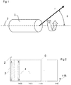
- Figure 1 depicts a spherical coordinate system that can be used to describe a set of imaging data acquired from a volume using an imaging assembly 1.
- a sequence of intracardiac echo (ICE) data samples collected along 'r' can be represented as a one-dimensional image of N unique picture elements (pixels), with each element corresponding to a unique sampling of ultrasound data.
- the spatial length of 'r' corresponds to the imaging depth of the image transducer and may consequently define the spacing between pixels as being equal to r/N in the case of uniform sampling.
- Successive 1D imaging data vectors are acquired as the imaging assembly moves around the rotational axis 2 (measured by 'theta' ( ⁇ )).
- Figure 2 depicts a collection of successively acquired 1D imaging data vectors 3 arranged according to increasing rotational angle 'theta' ( ⁇ ).
- Embodiments may treat this arrangement as a two-dimensional image 5 , with picture elements along the 'r'-axis 2 representing imaging data samples at increasing distances from the imaging assembly and picture elements along the ⁇ -axis 115 representing imaging data samples at increasing angles around the rotational axis of an imaging assembly.
- This continuous collection and arrangement of imaging data would result in a pixel matrix with an ever increasing width.
- This representation is also appropriately described as a temporal arrangement with the oldest sampled vectors lying at the left edge of Figure 2 and the newest being continuously added on the right.
- the ⁇ -axis 115 does not necessarily have a linear relationship with time, as the rotational velocity may vary with time, such as to change the tilt angle (represented as 'phi' ( ⁇ ) in Figure 1 ) of an imaging beam.
- Practical embodiments may divide the large two-dimensional array of acquired samples into imaging frames 4 corresponding to complete revolutions of the imaging assembly ('theta' ( ⁇ ) ranging from 0 to 2pi radians).
- Single 2D imaging frames need not be restricted to having a fixed tilt angle of 'phi' ( ⁇ ).
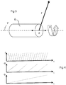
- Figure 3 depicts an alternate configuration of an imaging assembly 6 where the tilting degree of freedom described by 'phi' ( ⁇ ) in Figure 1 is removed and a longitudinal degree of freedom d is added. Imaging data is again collected along vector 'r' as the imaging assembly rotates about 7 (the corresponding angle represented as 'theta' ( ⁇ )) while the entire assembly is translated along 7 (the corresponding distance represented by 'd') resulting in the collection of imaging data from a cylindrical volume.
- axis 7 is shown as a straight line, in the case of flexible imaging catheters, axis 7 may be a curved path, as is common in the practice of intravascular imaging and pullback acquisitions.
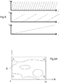
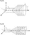
- Figure 4 depicts the relative temporal relationship between data acquisition along each of the three imaging axes which is characteristic of many embodiments. Acquisition along the radial axis 'r' is fastest followed by acquisition about the longitudinal axis 'theta' ( ⁇ ) followed again by acquisition along the tilt axis 'phi' ( ⁇ ), which may typically be the slowest.
- Figure 5 depicts an analogous temporal relationship reflecting the configuration depicted in Figure 3 with the collection of data along longitudinal axis 'd' being typically the slowest.
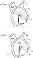
- a frame of 2D image data 8 can be represented in a three dimensional manner that reflects the physically travelled path of an energy beam that is emitted from and/or received by an imaging assembly.
- Figure 7B depicts said travelled path for a number of revolutions about fixed angles of 'phi' ( ⁇ ) and
- Figure 7C depicts the travelled path during an acquisition where the tilt angle varies smoothly.
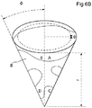
- Figure 6A depicts an acquired 2D image frame produced by a single revolution of the imaging assembly covering the range of possible 'theta' ( ⁇ ) values while angle 'phi' ( ⁇ ) is constant.
- Figure 6B depicts a possible embodiment using the same acquired imaging data frame 8 providing a visual representation of the rotational angle 'theta' ( ⁇ ) and fixed tilt angle 'phi' ( ⁇ ).
- the 2D imaging data frame is mapped to a wireframe conical geometry (defined by 'r', 'theta' ( ⁇ ) and 'phi' ( ⁇ ) that is representative of the region sampled within the volume during acquisition by the imaging device.
- U.S. Patent No. 8,214,010 describes potential embodiments where acquired image data is reconstructed into a 3D volume representation with spatial extents spanning ranges of spherical coordinate dimensions 'r', 'theta' ( ⁇ ) and 'phi' ( ⁇ ).
- Some embodiments of the present disclosure extend upon those visualization embodiments for 3D reconstructions by creating composite volumetric representations of imaging data sets that incorporate texture mapping of 2D imaging data frames.
- Other embodiments of the present disclosure incorporate means of representing 3D reconstructions for image data sets acquired using the imaging assembly depicted in Figure 3 .
- Figure 8A depicts the acquisition of image data as the imaging assembly 6 is pulled along the longitudinal axis 7.
- the angle of the transducer is fixed at an angle 'phi' ( ⁇ ) typically (but not necessarily) close to ninety degrees measured from the longitudinal axis 7.
- ⁇ typically (but not necessarily) close to ninety degrees measured from the longitudinal axis 7.
- a reconstructed volumetric representation of data acquired along such a trajectory would reside within a volume that resembles a cylinder. In this case, the data is acquired in fixed increments along the longitudinal axis 7.
- the continuous acquisition of imaging data while the imaging assembly 6 moves along the longitudinal axis 7 at a constant rate would result in the collection pattern depicted in Figure 8B .
- Volumetric representations can be created in a similar fashion for each of the depicted acquisition trajectories.
- Figure 7A depicts the first embodiment incorporating a 2D texture map 11 (corresponding to a single angle 'phi' ( ⁇ ) combined with the representation of a 3D reconstruction 12.
- a 2D texture map 11 corresponding to a single angle 'phi' ( ⁇ ) combined with the representation of a 3D reconstruction 12.
- the three dimensional data lying outside the textured conical surface 11 has been excluded allowing visualization of the 2D image data 11 on the outside surface.
- This exclusion region is based on all image data represented at cone angles larger than that associated with the selected 2D imaging frame.
- This cone angle can be referred to as a clipping angle.
- Orienting the base of the cone 13 towards the observer facilitates viewing of the reconstructed 3D representation of image data on the inside of the conical surface.
- the 2D texture-mapped image has been acquired using the scanning pattern depicted in Figure 7B .
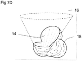
- Figure 7D depicts a similar embodiment incorporating a 2D texture map 14 with a reconstructed 3D representation 15.
- the three dimensional data occupying the interior of the cone (corresponding to values of 'phi' ( ⁇ ) less than that of the selected 2D imaging frame) has been excluded.
- the 3D conical volumetric representation of imaging data lying outside the surface of the cone 15 (corresponding to values of 'phi' ( ⁇ ) greater than that of the selected 2D imaging data frame) is now visible. This exclusion is based on all data at cone angles less than that associated with the selected 2D texture map 14. Again, this cone angle can be referred to as a clipping angle.
- Orientating the base of the cone 16 towards the observer allows observation of the 2D image data frame mapped onto the cone's interior surface.
- the selected 2D image frame representation 14 is appropriately positioned on the interior surface of the 3D conical volume representation 15 such that the anatomical structures depicted in both representations are aligned.
- the aforementioned composite visualization embodiments incorporated, by example, the identification of a single frame of imaging data to serve as the boundary separating the visible and non-visible portions of the conical volumetric representation.
- Potential embodiments may incorporate the selection of this boundary frame by either the operator or by the system itself. Any 2D frame of imaging data within the collected imaging data set may serve as the boundary frame, including those without a fixed angle 'phi' ( ⁇ ) throughout the frame.
- embodiments may include a means of varying the transparency of all, or portions 29 of, the 2D and/or 3D component of the representation. This can be accomplished by associating an alpha channel with the depicted imagery where every image pixel of the representation contains both an intensity component (corresponding to a sample of image data) and an operator definable transparency component. Furthermore, transparency may also be used as the means for depicting the excluded regions of volumetric representations referenced in the preceding discussion centering on figures 7A and 7D . Embodiments may facilitate adjustment of apply transparency levels through either the system or the operator.
- potential embodiments may also include a means of associating a color hue with all, or portions of, the 2D and/or 3D components of the representation.
- Color hue can be added to an image data visualization by assigning to each representative pixel a red, green and blue color channel value.
- the applied color hue may be varied by either the system or the operator and may be varied in conjunction with any applied transparency cue.
- FIG. 9 An example embodiment is depicted in Figure 9 where the transparency level (alpha channel value) and/or color hue (red, green and/or blue channel value) for every image pixel is determined by a function of that pixel's intensity (image data sample). In this case, bright pixels may be distinguished from dark pixels by differences in color hue and/or transparency. The operator may choose certain thresholds for pixel intensity values to reflect particular colors and/or transparency levels.
- Per-pixel transparency can be used to hide the depicted regions of tissue falling below a certain pixel intensity value thus revealing the depiction of tissue behind it.
- the inverse application of transparency values and/or color hue could be used to isolate particular regions from surrounding tissue. Embodiments would facilitate this per-pixel application of visual cues to portions of either the conical volume representation and/or the texture-mapped conical imaging frame.
- the nature of the imaging system described in U.S. Patent No. 8,214,010 is such that the acquisition of image data in three dimensions is rate limited by the slowest acquisition axis.
- the temporal resolution of a volumetric image is defined by the time interval between updates of image data in a volumetric representation for a given set of spatial extents (ranges of the acquisition axes).
- a volumetric representation of an image data set for some range of values of 'r', 'theta' ( ⁇ ) and 'phi' ( ⁇ ) of the imaging assembly is depicted in Figure 1 .
- the time interval needed to acquire fresh image data across the ranges of 'r', 'theta' ( ⁇ ) and 'phi' ( ⁇ ) and process for display another volumetric representation defines the temporal resolution of the volumetric image.
- a low temporal resolution image is not well suited to the task of displaying fast moving structures within imaged anatomy.
- a means of increasing the temporal resolution for a set of acquisitions is to reduce the extents of the region to be scanned. For example, reducing the range of scanned angles 'phi' ( ⁇ ) in a system utilizing the coordinate system described in Figure 1 would improve the temporal resolution of consecutively acquired image data sets. A similar effect would be achieved when reducing the range of scanned positions 'd' in a system utilizing the coordinate system described in Figure 3 .
- a combination of the above approaches may also be used.
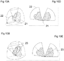
- Figures 10A through 10F depict an embodiment that achieves this.
- Figure 10A shows a volumetric representation of a set of imaging data acquired over a relatively large region of the volume, in this case, a wide range of tilt angles 'phi' ( ⁇ ) 22.
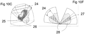
- Figure 10D depicts a cross-section of the same volumetric representation.
- Figure 10C depicts the volumetric representation composed with a smaller region of volumetric image data that is updated more frequently. Note that the range of angles 'phi' ( ⁇ ) 24 is smaller than range used for the entire volume 22.
- Figure 10F depicts a cross-section of the composite representation with the regions of high 27 and low 28 temporal resolution indicated.
- the composited region of interest can be of any size provided it is within the bounds provided by the imaging system.
- Figures 10B and 10E depict an embodiment in which the region of interest is a single frame of imaging data which, given the set of coordinate axes described in Figure 1 , is a single revolution of the imaging system about the axis 'theta' ( ⁇ ). The size and position of the region of interest need not remain static between updates from the imaging system.
- FIGs 10B and 10E there is shown an embodiment in which the region of interest described by the angle 'phi' ( ⁇ ) 23 continuously moves through the range of angles 22 defining the entire volumetric region and continuously updates the depicted representation as new image data frames are acquired from the imaging device.
- the system is advantageous for the system to be capable of determining when the position and/or orientation of the imaging device has changed as this affects the faithfulness of the composite visual representation, for example a user or system defined region of interest containing image data of a high temporal resolution 25.
- the imagery within this region will reflect movements of the imaging device more quickly than the surrounding regions of low temporal resolution 26.
- the imagery depicted in the region of interest may no longer spatially align with the imagery depicted in the surrounding contextual representation.
- an algorithm for detecting spatial misalignment between regions of high and low temporal resolution.
- the algorithm is defined as follows: Begin by examining the image data associated with the representative portions touching the boundaries of the region of interest and, for each pixel pair occupying either side of the boundary plane, compute their relative difference in intensity (image data sample value). The sum of the differences for all such pixel pairs lying on the boundary plane is a metric quantifying how alike depicted imagery is on either side. When said metric is above an operator or system defined threshold, the spatial alignment may be considered unsuitable for continued display. In such cases, embodiments of the system may proceed by reacquiring a fresh image-set for the entirety of the contextual volumetric representation.
- More comprehensive spatial misalignment detection algorithms may incorporate the image co-registration embodiments of Volume Registration and Motion Detection detailed elsewhere in this disclosure.
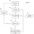
- the flow chart in Figure 11 presents the general series of steps an embodiment may follow to achieve the composite visualizations depicted in Figures 10A through 10F .
- the initial static volume is generated and displayed 31 after the system acquires image data 30 corresponding to a scanning field of view 22 , after which an operator or system defined region of interest 18 is defined 32 and then updated repeatedly as the imaging system scans the constrained region. Due to motion of the imaging probe and/or surrounding anatomy, the imaging data corresponding to the region of interest is evaluated for spatial alignment with the initial static volume 35. If the spatial alignment is deemed adequate, the image data representation of the region of interest is composed with contextual volumetric visualization 36. If the spatial alignment is deemed to be poor, an image set to represent the extents of the entire contextual volumetric region is reacquired 31 , thus starting the process over.
- Embodiments of the invention need not retain the same region of interest between successive compositions of acquired image data.
- the system may update the region of interest 37 or retain the region defined by the user 38.
- Additional embodiments incorporate the gated acquisition of imaging data to mitigate the effects of anatomical motion in the imaged region of interest.
- Such embodiments may incorporate an ECG signal to synchronize the acquisition image data with the cardiac cycle.
- Imagery acquired in such a fashion can yield volumetric representations of the heart at a single phase of the cardiac cycle.
- imaging data can be collected over several cardiac cycles thus enabling a four-dimensional reconstruction (multiple 3D volumetric representations varying with time).
- Embodiments may incorporate imaging data obtained through gated acquisition in some or all portions of the composite visual representation.
- Additional embodiments may be provided which incorporate visual cues used to distinguish the imagery depicted within the region of interest from the imagery depicted in the contextual surroundings.
- visual cues may include the application of transparency and/or color to the visualized image data.
- Methods for applying said visualization cues would be the same as those described in previous embodiments and this application of said visual cues can be controlled by either the system or the user.
- another possible embodiment may be provided in which the particular visual cue is a reflection of the amount of time that has elapsed since the visualized imagery was acquired by the imaging device. For example, the transparency (alpha value) of pixels constituting the imagery depicted in the contextual volume portion of the composite visualization is calculated as a function of the time from acquisition.
- the application of visual cues are important in this embodiment as they convey the relative differences in temporal resolution between the different portions of the composite visualization.
- High temporal resolution regions are more likely to accurately reflect anatomical regions prone to movement.
- depicted regions of low temporal resolution may become less trustworthy as the time interval from acquisition increases.
- Motion of the imaging probe will affect the coherence between a static portions volume reconstruction and the dynamic nature of the imaging device.
- One method to provide increased coherence is to perform a registration between current imaging information and a static historical volume.
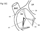
- the catheter tip 41 is located inside a cardiac chamber. Begin by performing a "dense" scan 40 of the interior space thus acquiring a volume of high spatial resolution 45. For every line of image data acquired along r (as depicted in Figure 1 ), for given angles of 'theta' ( ⁇ ) and 'phi' ( ⁇ ), scan for the first point (starting from the origin) that represents cardiac tissue.
- Such a point could be determined by an increase of signal intensity from that which is characteristic of blood to that which is characteristic of heart tissue.
- the set of all points described by (r(i), 'theta' ( ⁇ ), 'phi' ( ⁇ ) where 'i' represents the first incidence of cardiac tissue) collected for each r-vector defines the interior surface of the chamber 39.
- This collection of points may be stored as an attribute of the dense volumetric scan. The time required to perform this dense scan is typically long.
- the following steps may be performed ( Figure 13 ).
- the time required to perform this scan is reduced because the range of angles in 'theta' ( ⁇ ) and/or 'phi' ( ⁇ ) can be traversed much more quickly.
- the time to compute this second map is less because of the reduced spatial resolution of the volume.
- each surface is represented by a collection of points.
- a linear-least-squares best-fit approach can be used to determine the best positional correlation between two data sets, the product of which is the transformation (position and orientation) of the origin of one data set with respect to the other. This defines the change in location of the catheter tip from one volumetric scan 41 to the other 43.
- RMS root-mean-square
- an embodiment which incorporates the detection of the transition into cardiac tissue along the r-dimension using a succession of r-vectors. Instead of defining the transition at a point, it can now be defined along an edge.
- the surface contour of the cardiac chamber can be expressed as a collection of edges rather than points.
- a modified co-registration algorithm can then be employed to determine the transformation between the acquired volumes and again yield an acceptance criterion indicative of the quality of the fit.
- Refinements of the above embodiment may incorporate additional properties of the detected edge-space like strength (sharpness of image intensity change) or normal (orientation of the edge with respect to the acquisition origin). This additional information can be incorporated into the algorithm (performed in 47 ) used to determine the correspondence between the two image volumes.
- Potential embodiments need not be limited by the parameters used to acquire the sparse volumetric dataset. Rather than re-scanning the entire range, a much narrower range 44 of 'theta' ( ⁇ ) and/or 'phi' ( ⁇ ) is scanned (as depicted in Figure 12C ) as a means of reducing the time required to perform a scan for the purpose of registration.
- the methodologies described above for identifying the interior surface of the cardiac chamber and registering that surface with another acquisition still apply when the second acquisition has reduced 'theta' ( ⁇ ) and/or 'phi' ( ⁇ ) extents.
- embodiments may reduce the sub-volume down to just a single revolution about the 'theta' ( ⁇ ) axis which, when tilt angle 'phi' ( ⁇ ) is held constant, is representative of a single conical image frame.
- the aforementioned registration methods are still valid when considering a single imaging frame however it is expected that the likelihood of successfully registering smaller data sets to the larger contextual volume will be reduced.
- Restricting the scanning region for the purpose of registration may have advantages beyond simply reducing acquisition time.
- the physician through the application of some therapy, may physically alter appearance of tissue within the scanned field of view. If the contextual volume was acquired prior to this event then successive acquisitions, acquired for the purposes of co-registration, will no longer reflect the original tissue characteristics. In these cases, registration accuracy would improve if the tissue regions that were altered were excluded from the set of imaging data used for co-registration.
- the operator through the use of a 3D region of interest selection, manually defining the area or areas that have been altered and the system then ignores those regions when computing the next co-registration transform.
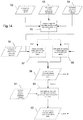
- an embodiment includes incorporating information defining a set of "expected" catheter positions 51 based on the current known location of the catheter as well as its characteristic degrees of freedom 54. This additional information can be used to remove computed registration transformations from consideration 57 and/or reduce their weighting when considering them as a portion of the output from a multitude of registration methodologies 58.
- Figure 14 depicts a flowchart detailing an algorithm making use of this type of information to filter the set of candidate catheter positions/orientations 56.
- an embodiment which involves the incorporation of information additionally characterizing the expected trajectory of the imaging device 60. This information would ultimately come from the operator 61 as she would have knowledge of the procedure being performed.
- an embodiment includes the case where an operator wishes to perform a directed puncture or injection. The operator could indicate the intended position and orientation of the imaging device via the user interface of the imaging system at which point the system would determine the appropriate trajectory. The operator may also select a maneuver from a preprogrammed set of maneuvers, each of which could have its own means for determining expected position and orientation.
- the accuracy of three dimensional volume reconstruction is affected by cardiac motion and gating the acquisition of imaging data to portions of the cardiac cycle can improve accuracy.
- co-registration accuracy is also effected by cardiac motion so employing gated acquisition techniques for co-registered image data sets will reduce co-registration error.
- imaging sequences of low temporal resolution are affected by motion and benefit from gating algorithms known in the art, such as ECG gating, gating based on respiratory motion, etc.
- volume complexity can be quantified by inner surface smoothness, distribution of pixel edge strength and edge normal.
- the present disclosure provides a system that, when provided the extents of a three-dimensional sub-volume representation in one reconstruction, have the capability to automatically identify a sub-volume representation corresponding to the same portion of anatomy in subsequent reconstructions. Embodiments employing this capability must be able to account for slight variations in the size, location and orientation the structure of interest. These variations can be the result of movement of the imaging catheter and/or motion of the imaged cardiac structure itself.
- the Figure 15 shows another embodiment.
- the operator identifies a distinct volumetric region 65 within a reconstructed dataset 64 either manually (e.g., 3D region-of-interest selection) or through assisted selection aided by an automatic segmentation algorithm.
- the present disclosure teaches the use of a recursive seed fill algorithm over a 3D pixel matrix employing a user or system defined tolerance.
- the seed 3D image pixel (voxel) selected by the operator. It is assumed that this voxel is located within the depicted boundaries of the region of interest within the volumetric representation.
- the algorithm looks at all voxels connected to the seed (neighbors) and 'colors' them if their intensity is equivalent (within the defined tolerance) to the seed. In a recursive fashion, the algorithm examines the neighbors of each colored voxel, coloring the neighbors when their intensity matches (again, with the defined tolerance) that of the seed.
- the colored region of connected voxels grows until no new voxels remain to be colored.
- the smallest enveloping bounds of the colored voxel region represents the system assisted selection. Adjusting the tolerance prior to performing the selection will affect how many voxels are colored and therefore the extents of the selection. Plainly, the intensity of the selected seed voxel will affect which voxels are included in the selection.
- the identified sub-volume must have, at least approximately, an enveloping boundary characterized by a distinct region of differing voxel intensity.
- the system characterizes 66 the sub-volume by determining and processing its geometric center, center of mass, orientation (principle component axes), weighted orientation (weighted principle component axes), volume (voxel count) and/or dimensions along identified principle axes.
- the system highlights or hides 67 the region by applying either a hue or transparency visualization cue to the constituent sub-volume voxels.
- Visual cues can be applied to the identified region of the volume representation in the same manner as described in previous embodiments of the present invention.
- the same types of visual cues namely the application of color and/or transparency, would apply in the case of hiding or highlighting the volumetric region of interest.
- potential use of the same cues on the inverse region is also possible.
- the nature of the applied visualization is controlled by either the operator or the system.
- embodiments may employ an additional visual cue whereby the region of interest is positioned within the user interface such that it is always visible to the operator and never obstructed by other portions of the visualized representation or the other user elements of the user interface display. This feature of the embodiment is referred to as the centering view.
- Subsequent volumetric scans are now collected 68 from more recently acquired image data 72.
- the search for the sub-volume matching the one previously characterized volume starts 69 at the characterized center (mass or geometry) location.
- Automatic segmentation is again employed in an attempt to identify a volumetric region enveloping the center point.
- the system can bound the search to roughly the same dimensions as previously the characterized volume, accounting for small variations in the sub-volume orientation.
- Successful identification of the target region will depend on how closely an identified sub-volume matches the characteristics (location, orientation, volume, dimensions) of the region of interest.
- Successful re-characterization of the target region is recorded and may be used as input for the search in the next image volume representation 71.
- Additional embodiments may include an option to redefine the previously identified sub-volume characteristics with the results of the latest search 71 or some weighted average of each characteristic from the set of previous searches.
- Successful searches will result in the application of the same hide or highlight cue 67 to the depicted visual representation.
- representations corresponding to subsequent image set acquisitions where the target region was not identified the visual cue will not be applied.
- Failure to locate the region of interest in some number of (possibly zero) consecutively acquired image sets (or some minimum percentage of previously acquired image sets) results in the system abandoning future search attempts until such point that the operator reselects a region of interest 65.
- Figure 17 provides an exemplary, non-limiting implementation of computer control system 425 for implementing the methods and systems disclosed herein, which includes one or more processors 430 (for example, a CPU/microprocessor), bus 402 , memory 435 , which may include random access memory (RAM) and/or read only memory (ROM), one or more internal storage devices 440 (e.g. a hard disk drive, compact disk drive or internal flash memory), a power supply 445 , one more communications interfaces 450 , and various input/output devices and/or interfaces 460 such as a user interface for a clinician to provide various inputs, run simulations etc.
- processors 430 for example, a CPU/microprocessor
- bus 402 bus 402
- memory 435 which may include random access memory (RAM) and/or read only memory (ROM), one or more internal storage devices 440 (e.g. a hard disk drive, compact disk drive or internal flash memory), a power supply 445 , one more communications interfaces 450 , and various input/output devices
- bus 402 is depicted as a single connection between all of the components, it will be appreciated that the bus 402 may represent one or more circuits, devices or communication channels which link two or more of the components.
- bus 402 often includes or is a motherboard.
- computer control system 425 may be, or include, a general purpose computer or any other hardware equivalents configured for operation in space.
- Computer control system 425 may also be implemented as one or more physical devices that are coupled to processor 430 through one of more communications channels or interfaces.
- computer control system 425 can be implemented using application specific integrated circuits (ASIC).
- ASIC application specific integrated circuits
- computer control system 425 can be implemented as a combination of hardware and software, where the software is loaded into the processor from the memory or over a network connection.
- Examples of computer-readable storage media include, but are not limited to, recordable and non-recordable type media such as volatile and non-volatile memory devices, read only memory (ROM), random access memory (RAM), flash memory devices, floppy and other removable disks, magnetic disk storage media, optical storage media (e.g., compact discs (CDs), digital versatile disks (DVDs), etc.), among others.
- the instructions can be embodied in digital and analog communication links for electrical, optical, acoustical or other forms of propagated signals, such as carrier waves, infrared signals, digital signals, and the like.
- the storage medium may be the internet cloud, or a computer readable storage medium such as a disc.
- Examples of computer-readable storage media include, but are not limited to, recordable and non-recordable type media such as volatile and non-volatile memory devices, read only memory (ROM), random access memory (RAM), flash memory devices, floppy and other removable disks, magnetic disk storage media, optical storage media (e.g., compact discs (CDs), digital versatile disks (DVDs), etc.), among others.
- the instructions can be embodied in digital and analog communication links for electrical, optical, acoustical or other forms of propagated signals, such as carrier waves, infrared signals, digital signals, and the like.
Landscapes
- Engineering & Computer Science (AREA)
- Physics & Mathematics (AREA)
- General Physics & Mathematics (AREA)
- Theoretical Computer Science (AREA)
- Computer Graphics (AREA)
- Computer Vision & Pattern Recognition (AREA)
- Computer Hardware Design (AREA)
- General Engineering & Computer Science (AREA)
- Software Systems (AREA)
- General Health & Medical Sciences (AREA)
- Health & Medical Sciences (AREA)
- Medical Informatics (AREA)
- Nuclear Medicine, Radiotherapy & Molecular Imaging (AREA)
- Radiology & Medical Imaging (AREA)
- Quality & Reliability (AREA)
- Ultra Sonic Daignosis Equipment (AREA)
- Image Processing (AREA)
- Apparatus For Radiation Diagnosis (AREA)
- Instruments For Viewing The Inside Of Hollow Bodies (AREA)
- Endoscopes (AREA)
- Image Analysis (AREA)
- Acyclic And Carbocyclic Compounds In Medicinal Compositions (AREA)
Applications Claiming Priority (2)
| Application Number | Priority Date | Filing Date | Title |
|---|---|---|---|
| US201361801284P | 2013-03-15 | 2013-03-15 | |
| PCT/CA2014/050283 WO2014139032A1 (en) | 2013-03-15 | 2014-03-17 | Data display and processing algorithms for 3d imaging systems |
Publications (3)
| Publication Number | Publication Date |
|---|---|
| EP2973424A1 EP2973424A1 (en) | 2016-01-20 |
| EP2973424A4 EP2973424A4 (en) | 2016-10-26 |
| EP2973424B1 true EP2973424B1 (en) | 2018-02-21 |
Family
ID=51535749
Family Applications (1)
| Application Number | Title | Priority Date | Filing Date |
|---|---|---|---|
| EP14764241.7A Not-in-force EP2973424B1 (en) | 2013-03-15 | 2014-03-17 | Data display and processing algorithms for 3d imaging systems |
Country Status (6)
| Country | Link |
|---|---|
| US (2) | US9786056B2 (ja) |
| EP (1) | EP2973424B1 (ja) |
| JP (2) | JP6393698B2 (ja) |
| AU (1) | AU2014231354B2 (ja) |
| BR (1) | BR112015023723A2 (ja) |
| WO (1) | WO2014139032A1 (ja) |
Families Citing this family (9)
| Publication number | Priority date | Publication date | Assignee | Title |
|---|---|---|---|---|
| EP3424403B1 (en) * | 2016-03-03 | 2024-04-24 | Sony Group Corporation | Medical image processing device, system, method, and program |
| WO2018123801A1 (ja) * | 2016-12-28 | 2018-07-05 | パナソニック インテレクチュアル プロパティ コーポレーション オブ アメリカ | 三次元モデル配信方法、三次元モデル受信方法、三次元モデル配信装置及び三次元モデル受信装置 |
| AU2018225834B2 (en) * | 2017-02-24 | 2022-12-01 | Sunnybrook Research Institute | Systems and methods for noise reduction in imaging |
| JP7520037B2 (ja) * | 2019-04-02 | 2024-07-22 | コーニンクレッカ フィリップス エヌ ヴェ | 非造影頭部ctにおける重大領域の迅速検出及びインデックス付けのための自動化システム |
| US10671934B1 (en) | 2019-07-16 | 2020-06-02 | DOCBOT, Inc. | Real-time deployment of machine learning systems |
| US11423318B2 (en) * | 2019-07-16 | 2022-08-23 | DOCBOT, Inc. | System and methods for aggregating features in video frames to improve accuracy of AI detection algorithms |
| US20210052146A1 (en) * | 2019-08-19 | 2021-02-25 | Covidien Lp | Systems and methods for selectively varying resolutions |
| US20210315636A1 (en) * | 2020-04-09 | 2021-10-14 | Acclarent, Inc. | User interface for image guided surgery system |
| US11100373B1 (en) | 2020-11-02 | 2021-08-24 | DOCBOT, Inc. | Autonomous and continuously self-improving learning system |
Family Cites Families (54)
| Publication number | Priority date | Publication date | Assignee | Title |
|---|---|---|---|---|
| US5373845A (en) | 1992-05-22 | 1994-12-20 | Echo Cath, Ltd. | Apparatus and method for forward looking volume imaging |
| US5373849A (en) | 1993-01-19 | 1994-12-20 | Cardiovascular Imaging Systems, Inc. | Forward viewing imaging catheter |
| US6059727A (en) * | 1995-06-15 | 2000-05-09 | The Regents Of The University Of Michigan | Method and apparatus for composition and display of three-dimensional image from two-dimensional ultrasound scan data |
| US6002738A (en) * | 1995-07-07 | 1999-12-14 | Silicon Graphics, Inc. | System and method of performing tomographic reconstruction and volume rendering using texture mapping |
| JP3296193B2 (ja) * | 1996-06-26 | 2002-06-24 | 富士写真光機株式会社 | 超音波画像生成装置 |
| US5871019A (en) * | 1996-09-23 | 1999-02-16 | Mayo Foundation For Medical Education And Research | Fast cardiac boundary imaging |
| US6126603A (en) * | 1997-05-07 | 2000-10-03 | General Electric Company | Method and apparatus for segmenting color flow mode data using velocity information in three-dimensional ultrasound imaging |
| US6181348B1 (en) * | 1997-09-22 | 2001-01-30 | Siemens Corporate Research, Inc. | Method for selective volume visualization via texture mapping |
| JPH11137556A (ja) * | 1997-11-10 | 1999-05-25 | Olympus Optical Co Ltd | 超音波プローブ |
| US6159152A (en) | 1998-10-26 | 2000-12-12 | Acuson Corporation | Medical diagnostic ultrasound system and method for multiple image registration |
| US6315732B1 (en) | 1999-07-20 | 2001-11-13 | Scimed Life Systems, Inc. | Imaging catheter and methods of use for ultrasound-guided ablation |
| US6750873B1 (en) * | 2000-06-27 | 2004-06-15 | International Business Machines Corporation | High quality texture reconstruction from multiple scans |
| JP4095332B2 (ja) * | 2001-04-24 | 2008-06-04 | 株式会社東芝 | 超音波診断装置 |
| US6572547B2 (en) * | 2001-07-31 | 2003-06-03 | Koninklijke Philips Electronics N.V. | Transesophageal and transnasal, transesophageal ultrasound imaging systems |
| CN1287741C (zh) | 2001-07-31 | 2006-12-06 | 皇家菲利浦电子有限公司 | 经食道的以及经鼻、食道的超声成像系统 |
| USRE45759E1 (en) * | 2001-07-31 | 2015-10-20 | Koninklijke Philips N.V. | Transesophageal and transnasal, transesophageal ultrasound imaging systems |
| US20060025689A1 (en) * | 2002-06-07 | 2006-02-02 | Vikram Chalana | System and method to measure cardiac ejection fraction |
| US7520857B2 (en) * | 2002-06-07 | 2009-04-21 | Verathon Inc. | 3D ultrasound-based instrument for non-invasive measurement of amniotic fluid volume |
| US6825838B2 (en) * | 2002-10-11 | 2004-11-30 | Sonocine, Inc. | 3D modeling system |
| US20040215077A1 (en) * | 2002-11-08 | 2004-10-28 | Witt Jerome F. | Color ensemble interleave with artifact elimination in time-gated anatomical imaging |
| US7599730B2 (en) * | 2002-11-19 | 2009-10-06 | Medtronic Navigation, Inc. | Navigation system for cardiac therapies |
| US7693563B2 (en) * | 2003-01-30 | 2010-04-06 | Chase Medical, LLP | Method for image processing and contour assessment of the heart |
| US9470801B2 (en) * | 2004-01-13 | 2016-10-18 | Spectrum Dynamics Llc | Gating with anatomically varying durations |
| US20050237336A1 (en) * | 2004-04-23 | 2005-10-27 | Jens Guhring | Method and system for multi-object volumetric data visualization |
| JP4577504B2 (ja) * | 2005-03-31 | 2010-11-10 | 富士フイルム株式会社 | 画像診断装置 |
| US20060253024A1 (en) | 2005-04-26 | 2006-11-09 | Altmann Andres C | Software product for three-dimensional cardiac imaging using ultrasound contour reconstruction |
| WO2006121851A2 (en) | 2005-05-05 | 2006-11-16 | Volcano Corporation | Capacitive microfabricated ultrasound transducer-based intravascular ultrasound probes |
| RU2008106929A (ru) * | 2005-07-26 | 2009-09-10 | Конинклейке Филипс Электроникс, Н.В. (Nl) | Определение области сердца на основании анализа движения мелкомасштабной реконструкции |
| US7918793B2 (en) * | 2005-10-28 | 2011-04-05 | Biosense Webster, Inc. | Synchronization of ultrasound imaging data with electrical mapping |
| US8105239B2 (en) * | 2006-02-06 | 2012-01-31 | Maui Imaging, Inc. | Method and apparatus to visualize the coronary arteries using ultrasound |
| US20070255137A1 (en) * | 2006-05-01 | 2007-11-01 | Siemens Medical Solutions Usa, Inc. | Extended volume ultrasound data display and measurement |
| US20080009722A1 (en) * | 2006-05-11 | 2008-01-10 | Constantine Simopoulos | Multi-planar reconstruction for ultrasound volume data |
| CN101473349B (zh) | 2006-06-23 | 2013-03-27 | 皇家飞利浦电子股份有限公司 | 用于三维超声成像的方法和装置 |
| EP2062534B1 (en) * | 2006-09-11 | 2014-04-16 | Panasonic Corporation | Ultrasonographic device |
| ATE497729T1 (de) | 2006-10-02 | 2011-02-15 | Hansen Medical Inc | System für dreidimensionale ultraschall-abbildung |
| TW200837378A (en) * | 2006-10-20 | 2008-09-16 | Koninkl Philips Electronics Nv | Methods and apparatus for high speed image acquisition rates in 3D medical imaging |
| CN101662980B (zh) * | 2007-01-19 | 2013-02-27 | 桑尼布鲁克健康科学中心 | 用于成像探头的扫描机构 |
| US8303502B2 (en) * | 2007-03-06 | 2012-11-06 | General Electric Company | Method and apparatus for tracking points in an ultrasound image |
| US8057394B2 (en) * | 2007-06-30 | 2011-11-15 | St. Jude Medical, Atrial Fibrillation Division, Inc. | Ultrasound image processing to render three-dimensional images from two-dimensional images |
| US8090168B2 (en) | 2007-10-15 | 2012-01-03 | General Electric Company | Method and system for visualizing registered images |
| WO2009053896A2 (en) * | 2007-10-26 | 2009-04-30 | Koninklijke Philips Electronics, N.V. | Closed loop registration control for multi-modality soft tissue imaging |
| US8320711B2 (en) * | 2007-12-05 | 2012-11-27 | Biosense Webster, Inc. | Anatomical modeling from a 3-D image and a surface mapping |
| US8270694B2 (en) | 2008-04-23 | 2012-09-18 | Aditya Koolwal | Systems, methods and devices for correlating reference locations using image data |
| JP5253893B2 (ja) * | 2008-06-03 | 2013-07-31 | 株式会社東芝 | 医用画像処理装置、超音波診断装置、及び超音波画像取得プログラム |
| KR101107478B1 (ko) * | 2008-12-15 | 2012-01-19 | 삼성메디슨 주식회사 | 다수의 3차원 초음파 영상을 형성하는 초음파 시스템 및 방법 |
| US8265363B2 (en) * | 2009-02-04 | 2012-09-11 | General Electric Company | Method and apparatus for automatically identifying image views in a 3D dataset |
| US8724874B2 (en) * | 2009-05-12 | 2014-05-13 | Siemens Aktiengesellschaft | Fusion of 3D volumes with CT reconstruction |
| US10835207B2 (en) | 2009-12-23 | 2020-11-17 | Biosense Webster (Israel) Ltd. | Fast anatomical mapping using ultrasound images |
| EP2605693B1 (en) * | 2010-08-20 | 2019-11-06 | Veran Medical Technologies, Inc. | Apparatus for four dimensional soft tissue navigation |
| JP2012161460A (ja) | 2011-02-07 | 2012-08-30 | Fujifilm Corp | 画像処理装置および画像処理方法、並びに、画像処理プログラム |
| JP2013000414A (ja) * | 2011-06-17 | 2013-01-07 | Toshiba Corp | 超音波診断装置、超音波画像処理装置及び超音波画像取得プログラム |
| US9196092B2 (en) * | 2012-06-11 | 2015-11-24 | Siemens Medical Solutions Usa, Inc. | Multiple volume renderings in three-dimensional medical imaging |
| US20140071125A1 (en) * | 2012-09-11 | 2014-03-13 | The Johns Hopkins University | Patient-Specific Segmentation, Analysis, and Modeling from 3-Dimensional Ultrasound Image Data |
| US9629595B2 (en) | 2013-03-15 | 2017-04-25 | Hansen Medical, Inc. | Systems and methods for localizing, tracking and/or controlling medical instruments |
-
2014
- 2014-03-17 EP EP14764241.7A patent/EP2973424B1/en not_active Not-in-force
- 2014-03-17 JP JP2015561872A patent/JP6393698B2/ja not_active Expired - Fee Related
- 2014-03-17 WO PCT/CA2014/050283 patent/WO2014139032A1/en active Application Filing
- 2014-03-17 AU AU2014231354A patent/AU2014231354B2/en not_active Ceased
- 2014-03-17 BR BR112015023723A patent/BR112015023723A2/pt not_active IP Right Cessation
- 2014-03-17 US US14/777,092 patent/US9786056B2/en active Active
-
2017
- 2017-10-06 US US15/726,998 patent/US10699411B2/en active Active
-
2018
- 2018-08-27 JP JP2018157925A patent/JP6611880B2/ja active Active
Non-Patent Citations (1)
| Title |
|---|
| None * |
Also Published As
| Publication number | Publication date |
|---|---|
| US10699411B2 (en) | 2020-06-30 |
| JP2019048046A (ja) | 2019-03-28 |
| JP6393698B2 (ja) | 2018-09-19 |
| WO2014139032A1 (en) | 2014-09-18 |
| EP2973424A4 (en) | 2016-10-26 |
| JP6611880B2 (ja) | 2019-11-27 |
| EP2973424A1 (en) | 2016-01-20 |
| US20160027184A1 (en) | 2016-01-28 |
| BR112015023723A2 (pt) | 2017-07-18 |
| US9786056B2 (en) | 2017-10-10 |
| JP2016509889A (ja) | 2016-04-04 |
| AU2014231354B2 (en) | 2019-08-29 |
| US20180158190A1 (en) | 2018-06-07 |
| AU2014231354A1 (en) | 2015-09-24 |
Similar Documents
| Publication | Publication Date | Title |
|---|---|---|
| US10699411B2 (en) | Data display and processing algorithms for 3D imaging systems | |
| KR102269467B1 (ko) | 의료 진단 이미징에서의 측정 포인트 결정 | |
| EP3003161B1 (en) | Method for 3d acquisition of ultrasound images | |
| US10362941B2 (en) | Method and apparatus for performing registration of medical images | |
| KR101932721B1 (ko) | 의료 영상들의 정합 방법 및 장치 | |
| US20140303499A1 (en) | Ultrasound diagnostic apparatus and method for controlling the same | |
| US20050249393A1 (en) | Method for medical imaging and image processing, computed tomography machine, workstation and computer program product | |
| BR112015004061B1 (pt) | Sistema de geração de imagens por ultrassom para a inspeção de um objeto em um volume, e método para a provisão de uma imagem por ultrassom tridimensional de um objeto em um volume. | |
| US10278663B2 (en) | Sensor coordinate calibration in an ultrasound system | |
| JP7286773B2 (ja) | 3d超音波撮像を使用した定量的腹部大動脈瘤分析のためのシステム及び方法 | |
| US11278259B2 (en) | Thrombus detection during scanning | |
| CN115426954A (zh) | 用于生成路线图图像的双平面和三维超声图像采集以及相关联的系统和设备 | |
| US20170169609A1 (en) | Motion adaptive visualization in medical 4d imaging | |
| US7376254B2 (en) | Method for surface-contouring of a three-dimensional image | |
| WO2007049207A1 (en) | System and method for generating for display two-dimensional echocardiography views from a three-dimensional image | |
| WO2020133236A1 (zh) | 一种脊柱的成像方法以及超声成像系统 | |
| US12089997B2 (en) | System and methods for image fusion | |
| US20240177437A1 (en) | Ultrasound imaging system and method for generating and displaying a colorized surface rendering | |
| CN118576241A (zh) | 肝脏超声信息的显示方法和超声成像系统 |
Legal Events
| Date | Code | Title | Description |
|---|---|---|---|
| PUAI | Public reference made under article 153(3) epc to a published international application that has entered the european phase |
Free format text: ORIGINAL CODE: 0009012 |
|
| 17P | Request for examination filed |
Effective date: 20150828 |
|
| AK | Designated contracting states |
Kind code of ref document: A1 Designated state(s): AL AT BE BG CH CY CZ DE DK EE ES FI FR GB GR HR HU IE IS IT LI LT LU LV MC MK MT NL NO PL PT RO RS SE SI SK SM TR |
|
| AX | Request for extension of the european patent |
Extension state: BA ME |
|
| RAP1 | Party data changed (applicant data changed or rights of an application transferred) |
Owner name: SUNNYBROOK RESEARCH INSTITUTE Owner name: CONAVI MEDICAL INC. |
|
| DAX | Request for extension of the european patent (deleted) | ||
| A4 | Supplementary search report drawn up and despatched |
Effective date: 20160922 |
|
| RIC1 | Information provided on ipc code assigned before grant |
Ipc: G06T 15/08 20110101AFI20160916BHEP Ipc: G06T 7/00 20060101ALI20160916BHEP Ipc: A61B 8/00 20060101ALI20160916BHEP Ipc: A61B 6/00 20060101ALI20160916BHEP Ipc: G06T 19/00 20110101ALI20160916BHEP |
|
| GRAP | Despatch of communication of intention to grant a patent |
Free format text: ORIGINAL CODE: EPIDOSNIGR1 |
|
| INTG | Intention to grant announced |
Effective date: 20170914 |
|
| GRAS | Grant fee paid |
Free format text: ORIGINAL CODE: EPIDOSNIGR3 |
|
| GRAA | (expected) grant |
Free format text: ORIGINAL CODE: 0009210 |
|
| AK | Designated contracting states |
Kind code of ref document: B1 Designated state(s): AL AT BE BG CH CY CZ DE DK EE ES FI FR GB GR HR HU IE IS IT LI LT LU LV MC MK MT NL NO PL PT RO RS SE SI SK SM TR |
|
| REG | Reference to a national code |
Ref country code: GB Ref legal event code: FG4D |
|
| REG | Reference to a national code |
Ref country code: CH Ref legal event code: EP |
|
| REG | Reference to a national code |
Ref country code: AT Ref legal event code: REF Ref document number: 972506 Country of ref document: AT Kind code of ref document: T Effective date: 20180315 |
|
| REG | Reference to a national code |
Ref country code: IE Ref legal event code: FG4D |
|
| REG | Reference to a national code |
Ref country code: DE Ref legal event code: R096 Ref document number: 602014021270 Country of ref document: DE |
|
| REG | Reference to a national code |
Ref country code: FR Ref legal event code: PLFP Year of fee payment: 5 |
|
| REG | Reference to a national code |
Ref country code: NL Ref legal event code: MP Effective date: 20180221 |
|
| REG | Reference to a national code |
Ref country code: LT Ref legal event code: MG4D |
|
| REG | Reference to a national code |
Ref country code: AT Ref legal event code: MK05 Ref document number: 972506 Country of ref document: AT Kind code of ref document: T Effective date: 20180221 |
|
| PG25 | Lapsed in a contracting state [announced via postgrant information from national office to epo] |
Ref country code: LT Free format text: LAPSE BECAUSE OF FAILURE TO SUBMIT A TRANSLATION OF THE DESCRIPTION OR TO PAY THE FEE WITHIN THE PRESCRIBED TIME-LIMIT Effective date: 20180221 Ref country code: NL Free format text: LAPSE BECAUSE OF FAILURE TO SUBMIT A TRANSLATION OF THE DESCRIPTION OR TO PAY THE FEE WITHIN THE PRESCRIBED TIME-LIMIT Effective date: 20180221 Ref country code: ES Free format text: LAPSE BECAUSE OF FAILURE TO SUBMIT A TRANSLATION OF THE DESCRIPTION OR TO PAY THE FEE WITHIN THE PRESCRIBED TIME-LIMIT Effective date: 20180221 Ref country code: NO Free format text: LAPSE BECAUSE OF FAILURE TO SUBMIT A TRANSLATION OF THE DESCRIPTION OR TO PAY THE FEE WITHIN THE PRESCRIBED TIME-LIMIT Effective date: 20180521 Ref country code: HR Free format text: LAPSE BECAUSE OF FAILURE TO SUBMIT A TRANSLATION OF THE DESCRIPTION OR TO PAY THE FEE WITHIN THE PRESCRIBED TIME-LIMIT Effective date: 20180221 Ref country code: FI Free format text: LAPSE BECAUSE OF FAILURE TO SUBMIT A TRANSLATION OF THE DESCRIPTION OR TO PAY THE FEE WITHIN THE PRESCRIBED TIME-LIMIT Effective date: 20180221 Ref country code: CY Free format text: LAPSE BECAUSE OF FAILURE TO SUBMIT A TRANSLATION OF THE DESCRIPTION OR TO PAY THE FEE WITHIN THE PRESCRIBED TIME-LIMIT Effective date: 20180221 |
|
| PG25 | Lapsed in a contracting state [announced via postgrant information from national office to epo] |
Ref country code: LV Free format text: LAPSE BECAUSE OF FAILURE TO SUBMIT A TRANSLATION OF THE DESCRIPTION OR TO PAY THE FEE WITHIN THE PRESCRIBED TIME-LIMIT Effective date: 20180221 Ref country code: SE Free format text: LAPSE BECAUSE OF FAILURE TO SUBMIT A TRANSLATION OF THE DESCRIPTION OR TO PAY THE FEE WITHIN THE PRESCRIBED TIME-LIMIT Effective date: 20180221 Ref country code: GR Free format text: LAPSE BECAUSE OF FAILURE TO SUBMIT A TRANSLATION OF THE DESCRIPTION OR TO PAY THE FEE WITHIN THE PRESCRIBED TIME-LIMIT Effective date: 20180522 Ref country code: BG Free format text: LAPSE BECAUSE OF FAILURE TO SUBMIT A TRANSLATION OF THE DESCRIPTION OR TO PAY THE FEE WITHIN THE PRESCRIBED TIME-LIMIT Effective date: 20180521 Ref country code: RS Free format text: LAPSE BECAUSE OF FAILURE TO SUBMIT A TRANSLATION OF THE DESCRIPTION OR TO PAY THE FEE WITHIN THE PRESCRIBED TIME-LIMIT Effective date: 20180221 Ref country code: AT Free format text: LAPSE BECAUSE OF FAILURE TO SUBMIT A TRANSLATION OF THE DESCRIPTION OR TO PAY THE FEE WITHIN THE PRESCRIBED TIME-LIMIT Effective date: 20180221 |
|
| PG25 | Lapsed in a contracting state [announced via postgrant information from national office to epo] |
Ref country code: IT Free format text: LAPSE BECAUSE OF FAILURE TO SUBMIT A TRANSLATION OF THE DESCRIPTION OR TO PAY THE FEE WITHIN THE PRESCRIBED TIME-LIMIT Effective date: 20180221 Ref country code: AL Free format text: LAPSE BECAUSE OF FAILURE TO SUBMIT A TRANSLATION OF THE DESCRIPTION OR TO PAY THE FEE WITHIN THE PRESCRIBED TIME-LIMIT Effective date: 20180221 Ref country code: PL Free format text: LAPSE BECAUSE OF FAILURE TO SUBMIT A TRANSLATION OF THE DESCRIPTION OR TO PAY THE FEE WITHIN THE PRESCRIBED TIME-LIMIT Effective date: 20180221 Ref country code: EE Free format text: LAPSE BECAUSE OF FAILURE TO SUBMIT A TRANSLATION OF THE DESCRIPTION OR TO PAY THE FEE WITHIN THE PRESCRIBED TIME-LIMIT Effective date: 20180221 Ref country code: RO Free format text: LAPSE BECAUSE OF FAILURE TO SUBMIT A TRANSLATION OF THE DESCRIPTION OR TO PAY THE FEE WITHIN THE PRESCRIBED TIME-LIMIT Effective date: 20180221 |
|
| REG | Reference to a national code |
Ref country code: CH Ref legal event code: PL |
|
| REG | Reference to a national code |
Ref country code: DE Ref legal event code: R097 Ref document number: 602014021270 Country of ref document: DE |
|
| PG25 | Lapsed in a contracting state [announced via postgrant information from national office to epo] |
Ref country code: SK Free format text: LAPSE BECAUSE OF FAILURE TO SUBMIT A TRANSLATION OF THE DESCRIPTION OR TO PAY THE FEE WITHIN THE PRESCRIBED TIME-LIMIT Effective date: 20180221 Ref country code: SM Free format text: LAPSE BECAUSE OF FAILURE TO SUBMIT A TRANSLATION OF THE DESCRIPTION OR TO PAY THE FEE WITHIN THE PRESCRIBED TIME-LIMIT Effective date: 20180221 Ref country code: CZ Free format text: LAPSE BECAUSE OF FAILURE TO SUBMIT A TRANSLATION OF THE DESCRIPTION OR TO PAY THE FEE WITHIN THE PRESCRIBED TIME-LIMIT Effective date: 20180221 Ref country code: MC Free format text: LAPSE BECAUSE OF FAILURE TO SUBMIT A TRANSLATION OF THE DESCRIPTION OR TO PAY THE FEE WITHIN THE PRESCRIBED TIME-LIMIT Effective date: 20180221 Ref country code: DK Free format text: LAPSE BECAUSE OF FAILURE TO SUBMIT A TRANSLATION OF THE DESCRIPTION OR TO PAY THE FEE WITHIN THE PRESCRIBED TIME-LIMIT Effective date: 20180221 |
|
| REG | Reference to a national code |
Ref country code: BE Ref legal event code: MM Effective date: 20180331 |
|
| REG | Reference to a national code |
Ref country code: IE Ref legal event code: MM4A |
|
| PLBE | No opposition filed within time limit |
Free format text: ORIGINAL CODE: 0009261 |
|
| STAA | Information on the status of an ep patent application or granted ep patent |
Free format text: STATUS: NO OPPOSITION FILED WITHIN TIME LIMIT |
|
| PG25 | Lapsed in a contracting state [announced via postgrant information from national office to epo] |
Ref country code: LU Free format text: LAPSE BECAUSE OF NON-PAYMENT OF DUE FEES Effective date: 20180317 |
|
| 26N | No opposition filed |
Effective date: 20181122 |
|
| PG25 | Lapsed in a contracting state [announced via postgrant information from national office to epo] |
Ref country code: IE Free format text: LAPSE BECAUSE OF NON-PAYMENT OF DUE FEES Effective date: 20180317 |
|
| PG25 | Lapsed in a contracting state [announced via postgrant information from national office to epo] |
Ref country code: CH Free format text: LAPSE BECAUSE OF NON-PAYMENT OF DUE FEES Effective date: 20180331 Ref country code: LI Free format text: LAPSE BECAUSE OF NON-PAYMENT OF DUE FEES Effective date: 20180331 Ref country code: BE Free format text: LAPSE BECAUSE OF NON-PAYMENT OF DUE FEES Effective date: 20180331 Ref country code: SI Free format text: LAPSE BECAUSE OF FAILURE TO SUBMIT A TRANSLATION OF THE DESCRIPTION OR TO PAY THE FEE WITHIN THE PRESCRIBED TIME-LIMIT Effective date: 20180221 |
|
| PG25 | Lapsed in a contracting state [announced via postgrant information from national office to epo] |
Ref country code: MT Free format text: LAPSE BECAUSE OF NON-PAYMENT OF DUE FEES Effective date: 20180317 |
|
| PG25 | Lapsed in a contracting state [announced via postgrant information from national office to epo] |
Ref country code: TR Free format text: LAPSE BECAUSE OF FAILURE TO SUBMIT A TRANSLATION OF THE DESCRIPTION OR TO PAY THE FEE WITHIN THE PRESCRIBED TIME-LIMIT Effective date: 20180221 |
|
| PG25 | Lapsed in a contracting state [announced via postgrant information from national office to epo] |
Ref country code: PT Free format text: LAPSE BECAUSE OF FAILURE TO SUBMIT A TRANSLATION OF THE DESCRIPTION OR TO PAY THE FEE WITHIN THE PRESCRIBED TIME-LIMIT Effective date: 20180221 |
|
| PG25 | Lapsed in a contracting state [announced via postgrant information from national office to epo] |
Ref country code: HU Free format text: LAPSE BECAUSE OF FAILURE TO SUBMIT A TRANSLATION OF THE DESCRIPTION OR TO PAY THE FEE WITHIN THE PRESCRIBED TIME-LIMIT; INVALID AB INITIO Effective date: 20140317 Ref country code: MK Free format text: LAPSE BECAUSE OF NON-PAYMENT OF DUE FEES Effective date: 20180221 |
|
| PG25 | Lapsed in a contracting state [announced via postgrant information from national office to epo] |
Ref country code: IS Free format text: LAPSE BECAUSE OF FAILURE TO SUBMIT A TRANSLATION OF THE DESCRIPTION OR TO PAY THE FEE WITHIN THE PRESCRIBED TIME-LIMIT Effective date: 20180621 |
|
| PGFP | Annual fee paid to national office [announced via postgrant information from national office to epo] |
Ref country code: FR Payment date: 20210323 Year of fee payment: 8 |
|
| PGFP | Annual fee paid to national office [announced via postgrant information from national office to epo] |
Ref country code: GB Payment date: 20210324 Year of fee payment: 8 Ref country code: DE Payment date: 20210319 Year of fee payment: 8 |
|
| REG | Reference to a national code |
Ref country code: DE Ref legal event code: R119 Ref document number: 602014021270 Country of ref document: DE |
|
| GBPC | Gb: european patent ceased through non-payment of renewal fee |
Effective date: 20220317 |
|
| PG25 | Lapsed in a contracting state [announced via postgrant information from national office to epo] |
Ref country code: GB Free format text: LAPSE BECAUSE OF NON-PAYMENT OF DUE FEES Effective date: 20220317 Ref country code: FR Free format text: LAPSE BECAUSE OF NON-PAYMENT OF DUE FEES Effective date: 20220331 Ref country code: DE Free format text: LAPSE BECAUSE OF NON-PAYMENT OF DUE FEES Effective date: 20221001 |