EP2971978B1 - Verfahren zum ermitteln eines betriebszustands einer dunstabzugshaubenanordnung - Google Patents
Verfahren zum ermitteln eines betriebszustands einer dunstabzugshaubenanordnung Download PDFInfo
- Publication number
- EP2971978B1 EP2971978B1 EP14707168.2A EP14707168A EP2971978B1 EP 2971978 B1 EP2971978 B1 EP 2971978B1 EP 14707168 A EP14707168 A EP 14707168A EP 2971978 B1 EP2971978 B1 EP 2971978B1
- Authority
- EP
- European Patent Office
- Prior art keywords
- extractor hood
- torque
- pressure difference
- function
- delivery volume
- Prior art date
- Legal status (The legal status is an assumption and is not a legal conclusion. Google has not performed a legal analysis and makes no representation as to the accuracy of the status listed.)
- Active
Links
Images




Classifications
-
- F—MECHANICAL ENGINEERING; LIGHTING; HEATING; WEAPONS; BLASTING
- F24—HEATING; RANGES; VENTILATING
- F24C—DOMESTIC STOVES OR RANGES ; DETAILS OF DOMESTIC STOVES OR RANGES, OF GENERAL APPLICATION
- F24C15/00—Details
- F24C15/20—Removing cooking fumes
-
- F—MECHANICAL ENGINEERING; LIGHTING; HEATING; WEAPONS; BLASTING
- F04—POSITIVE - DISPLACEMENT MACHINES FOR LIQUIDS; PUMPS FOR LIQUIDS OR ELASTIC FLUIDS
- F04D—NON-POSITIVE-DISPLACEMENT PUMPS
- F04D27/00—Control, e.g. regulation, of pumps, pumping installations or pumping systems specially adapted for elastic fluids
- F04D27/001—Testing thereof; Determination or simulation of flow characteristics; Stall or surge detection, e.g. condition monitoring
-
- B—PERFORMING OPERATIONS; TRANSPORTING
- B08—CLEANING
- B08B—CLEANING IN GENERAL; PREVENTION OF FOULING IN GENERAL
- B08B15/00—Preventing escape of dirt or fumes from the area where they are produced; Collecting or removing dirt or fumes from that area
- B08B15/02—Preventing escape of dirt or fumes from the area where they are produced; Collecting or removing dirt or fumes from that area using chambers or hoods covering the area
Definitions
- the present invention relates to a method for determining an operating state of an extractor hood arrangement.
- fan motors in the form of asynchronous motors were mainly used in extractor hoods due to their cost-effective design.
- the asynchronous motors are usually designed as capacitors or gap motors.
- the power control takes place via winding taps or a phase control.
- the torque-speed characteristic is predetermined by their design and can therefore only be changed to a limited extent.
- Extractor hoods can be used in kitchens as exhaust air or circulating air devices.
- the extractor hood When used as an exhaust air device, the extractor hood is connected to piping at the customer's, which leads the air filtered by the extractor hood out of the kitchen.
- the extractor hood In recirculation mode, on the other hand, the extractor hood is connected directly to the air volume of the kitchen interior, i.e. without the interposition of piping.
- an individual system characteristic curve results for a respective extractor hood.
- An intersection of the system characteristic with a delivery volume / pressure difference characteristic of the extractor hood results in the working point of the extractor hood.
- the working point here means the delivery volume and the pressure difference which occurs when the extractor hood is in operation.
- the delivery volume / pressure difference characteristic has a fixed relationship with the torque / speed characteristic of the asynchronous motor.
- the operating point varies from customer to customer depending on the installation situation of the extractor hood, which is present in each case.
- a manufacturer of extractor hoods does not know the respective installation situation at the customer.
- US 2012/0052792 A1 describes a ventilation unit for installation in a ventilation system.
- the ventilation unit includes a motor coupled to a fan and a power source.
- the fan unit has an electric motor for driving a fan wheel and a motor controller.
- WO 2010/065793 A1 describes a system and method for controlling an exhaust flow rate in an exhaust ventilation system of a range hood.
- US 2010/092275 A1 describes a household appliance with a fan speed control.
- US 2011/0000652 A1 describes a ventilation device and associated electronic equipment. This document discloses the preamble of claim 1.
- EP 2 765 359 A2 describes a method for monitoring an air flow in an air flow duct, in which a fan wheel driven by a fan motor and at least one air filter are arranged, the method detecting at least one operating parameter or a change in at least one operating parameter of the fan motor.
- One object of the present invention is to determine an operating state of an extractor hood arrangement comprising an extractor hood.
- a method for determining an operating state of an extractor hood arrangement comprising an extractor hood is provided. According to the method, the operating state is determined as a function of a torque / speed value pair of a fan motor of the extractor hood.
- the operating state is an exhaust air and a recirculation mode of the extractor hood assembly.
- the delivery volume is the volume of air (including any vapor) that is delivered per unit of time through the extractor hood and any piping connected to it by means of the fan motor.
- the pressure difference means the pressure difference with which the fan motor acts on the air volume.
- the pressure difference can be measured, for example, as the pressure difference between an air outlet of the extractor hood and the surroundings of the extractor hood.
- the pressure difference can be measured on the air outlet side as a static pressure difference in a pressure chamber.
- the delivery volume can be measured by means of a Venturi nozzle connected downstream of the pressure chamber.
- the extractor hood arrangement is thus set up to determine an operating state of the same at the customer's premises. Depending on the determined operating state, the extractor hood can then take additional measures automatically, for example adapting a torque-speed characteristic curve of the fan motor, i.e. in particular switching to a power mode or eco mode, as will be explained in more detail below. Additionally or alternatively, the operating status can also be displayed on a display device of the extractor hood, for example in the form of numbers, words and / or symbols.
- the fan motor is designed as an electronically commutated synchronous motor which is operated with direct current.
- Other names for such motors are BLDC (brushless direct current motor) or EC motor (electronically commutated motor).
- the present fan motor has a high flexibility with regard to its control options.
- the torque / speed characteristic and thus also a delivery volume / pressure difference characteristic of the extractor hood arrangement can be freely selected and adapted within certain limits.
- a control device of the extractor hood for controlling the fan motor can have software which defines a first and a second torque-speed characteristic.
- the torque-speed characteristics can be stored in a memory of the control device.
- the torque-speed characteristics can be stored in the form of tables of values.
- the control device can be provided, for example, in the form of a computer device, in particular as a microprocessor.
- a parameter can be the current consumed by the fan motor, for example.
- An evaluation device can have a function which, for example, maps the parameter in the form of a measured current intensity on a delivery volume and / or a pressure difference of the extractor hood.
- the function can be stored on the evaluation device, in particular on a memory thereof, for example by means of an equation or a table.
- the fan motor is an electrically commutated direct current motor which is controlled by means of a control device as a function of at least one torque-speed characteristic.
- the operating state is determined as a function of two parameters in the form of a torque-speed value pair of the at least one torque-speed characteristic curve.
- a respective torque-speed value pair can then be mapped to a current operating state of the extractor hood arrangement via a function by means of an evaluation device.
- an equation or a table can be stored as a function on the evaluation device, in particular in a memory thereof.
- the operating state is determined as a function of a function stored in a memory of the extractor hood and the two parameters in the form of a torque-speed value pair.
- the function can be provided discretely or continuously. For example, a table or equation can be used become.
- the function can be stored in a memory of an evaluation device of the extractor hood.
- the function in the production process of the extractor hood is stored in the memory.
- the function is therefore stored in the memory before the extractor hood is delivered to the customer.
- the function can be stored in the memory, whereupon the memory is built into the extractor hood. The function is then available when the customer is operating the extractor hood.
- the function is determined before the production process of the extractor hood by means of a test extractor hood arrangement, the delivery volume and / or pressure difference of which is varied.
- the function is determined by the fact that an extractor hood is not connected to any piping (recirculation mode) or piping of different lengths (exhaust air mode) in a test environment.
- the delivery volume and / or the pressure difference are detected by means of sensors and assigned to the at least one parameter.
- the delivery volume and / or the pressure difference can be assigned to a current strength supplied to the fan motor or to a torque-speed value pair of the fan motor. In the case of an electrically commutated DC motor, the torque and speed can be read out from the corresponding control device.
- the operating state is determined when the extractor hood is used as intended.
- the delivery volume and / or the pressure difference are determined by means of the method on site at the customer.
- the installation situation at hand for example also a piping length of a piping connected to the extractor hood, can be determined.
- the extractor hood arrangement exclusively comprises the extractor hood or the extractor hood and piping connected to it in an air-conducting manner.
- the extractor hood In the event that the extractor hood is operated as a circulating air device, no piping is provided, so that the extractor hood arrangement exclusively comprises the extractor hood.
- the extractor hood arrangement In the event that the extractor hood is operated as an exhaust air device, the extractor hood arrangement comprises the extractor hood and piping connected to it in an air-conducting manner.
- the piping can have different lengths and / or diameters and thus a variable air resistance.
- the operating state is shown on a display device of the extractor hood.
- the display device can be designed, for example, as a screen, in particular a TFT screen and / or a touch screen.
- the display device can be set up to display the current delivery volume, for example in the form of cubic meters per hour or in the form of a bar, the length of which depends on the amount of the delivery volume.
- a timer (timer) is started and / or, when the timer has reached a predetermined value, this is communicated to an operator by means of an output device.
- a timer can be started and this can be displayed to the operator on a display device.
- the timer can be displayed in the form of a bar, the length of which depends on the time that has passed.
- the operator can then decide for himself when to replace a recirculating air filter on the extractor hood.
- the operator can be informed via an output device that the circulating air filter is to be replaced when the timer reaches a predetermined value.
- the output device can be designed in the form of a display device, for example a TFT screen or touch screen, or a loudspeaker for generating a warning tone.
- a filter change symbol can be displayed on the display device when the timer has reached the predetermined value.
- a circulating air filter for example an activated carbon filter, is such a filter which is provided in the extractor hood in circulating air mode in order to enable better cleaning of the air to be filtered.
- Such a filter is not provided for exhaust air operation.
- the control device controls the fan motor with a torque-speed characteristic curve adapted to the circulating air or exhaust air operation.
- the electronically commutated direct current motor is controlled with a first or second torque-speed characteristic curve as a function of the determined operating state.
- a torque-speed characteristic curve can be adapted to a particular operating state.
- the first and second torque-speed characteristics can have a common point.
- the fact that the torque / speed characteristics have at least one common point means that the torque / speed characteristics have an identical torque / speed value pair or an identical profile in a first area (in at least one point) and in a second Range have a different torque-speed value pair or a different course.
- the first torque-speed characteristic curve can, for example, be assigned to a normal mode of a first operating stage of the extractor hood that can be selected by an operator.
- the second torque-speed characteristic curve can be assigned to a power mode of the extractor hood in the first operating stage.
- the power mode can correspond to an operation of the extractor hood in which the delivery volume is increased compared to the normal mode.
- the extractor hood detects, for example, that there is a recirculation mode in which a filter, in particular an activated carbon filter, is used, it can switch on the power mode automatically, that is, without user interaction.
- the control and evaluation device can be designed accordingly for this purpose.
- the extractor hood thus has, for example, improved extraction in each of four operating levels compared to a respective normal mode. In fact, such a reduction in suction power is compensated for in the recirculation mode, so that every customer, regardless of whether he uses the extractor hood in the recirculation mode or in the drain mode at home, will find a satisfactory extraction system.
- the electronically commutated fan motor can be controlled by a control device of the extractor hood with a first, second or third torque-speed characteristic.
- the first and third torque-speed characteristics can each be selected by an operator using an input device.
- the control device is further designed to control the fan motor based on the first or third torque-speed characteristic curve with the second torque-speed characteristic curve as a function of the determined operating state.
- an operator can switch the extractor hood between a first operating level (first torque-speed characteristic) and a second operating level (second torque-speed characteristic) by pressing a button, for example.
- the control device then automatically switches from the first torque-speed characteristic curve to the second torque-speed characteristic curve as a function of the determined operating state. In this way, it is possible, for example, to react flexibly to a system characteristic curve available at the customer.
- the first, second and / or third torque-speed characteristic curve has an asynchronous characteristic.
- the asynchronous characteristic therefore corresponds in principle to a torque-speed characteristic curve which corresponds to the shape of a horizontal "S".
- the asynchronous characteristic of the torque-speed characteristic curve comprises a valley, which is followed by a mountain in the direction of increasing speed. With increasing approach to the nominal speed, the torque drops asymptotically towards zero.
- the first torque-speed characteristic can be, for example, a normal mode of a first operating stage of the extractor hood.
- the second torque-speed characteristic curve can correspond to a power mode, eco mode or boost mode of the extractor hood.
- the second torque-speed characteristic is selected in order to avoid resonance effects of the extractor hood arrangement in the determined operating state.
- an extractor hood arrangement with an extractor hood which comprises a fan motor and an evaluation device, is provided.
- the evaluation device is set up to determine an operating state of the extractor hood arrangement as a function of the torque and speed of the fan motor.
- the evaluation device can be designed as a computer device, in particular a microprocessor.
- the extractor hood can also have a control device and / or a display device, as described above.
- the control and evaluation device can be integrated into a computer device.
- the extractor hood is preferably designed as a household appliance.
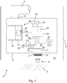
- Figure 1 shows schematically an extractor hood assembly 1 according to an embodiment.
- the extractor hood arrangement 1 comprises an extractor hood 2, which is arranged above a hob 3 in a kitchen.
- the extractor hood 2 can be designed, for example, as a hood or a chimney.
- the extractor hood 2 can be attached to a building wall 5 of the kitchen - like a piping 4.
- the extractor hood 2 conveys vapors 6 from above the hob 3 via an air inlet 7 to an air outlet 11 of the same.
- the air outlet 11 is connected in an air-conducting manner to the environment outside the kitchen via the piping 4.
- the extractor hood can be provided as a circulating air device, the air outlet 11 being connected to the interior 10 of the kitchen in an air-conducting manner.
- the extractor hood 2 comprises a fan wheel 13.
- the fan wheel 13 is driven by an electronically commutated fan motor 14.
- the fan wheel 13 forms a radial fan 16 with a surrounding spiral housing 15, which sucks the vapor 6 through a grease filter 12 in the area of the air inlet 7 and expels it through the air outlet 11.
- the radial fan 16 has to overcome the internal air resistance of the extractor hood 2, which results in particular from the radial fan 16 itself and internal piping 17.
- the radial fan 16 has to overcome the air resistance of the piping 4 (if this is present) in order to convey the air to the outside of the interior 10 of the kitchen.
- the internal air resistance of the extractor hood 2 results in a system characteristic curve of the same in recirculation mode.
- the sum of the internal air resistance of the extractor hood 2 and the air resistance of the piping 4 results in the system characteristic curve in exhaust air mode. Exemplary system characteristics are in Figure 3 and designated there by AK1, AK2 and AK3.
- the extractor hood 2 comprises a control and evaluation device 21 which controls the fan motor 14.
- the control and evaluation device 21 is designed, for example, as a microprocessor and comprises a memory 22.
- On the memory 22 are in the form of software in Figure 2 Torque-speed characteristics shown are stored.
- Figure 2 shows a first torque-speed characteristic curve DK1, a second torque-speed characteristic curve DK1a, a third torque-speed characteristic curve DK1b, a fourth torque-speed characteristic curve DK2, and a fifth torque-speed characteristic curve DK3.
- the torque M of the fan motor 14 is shown as a function of its speed n.
- the torque-speed characteristics DK1 to DK3 each have an asynchronous characteristic. That is, their shape corresponds to a lying "S". This also means that each of the torque-speed characteristics DK1 to DK3 has a tightening torque M A1 , M A2 , M A3 , a saddle torque M S1 , M S2 , M S3 , a tilting torque M K1 , M K1a, M K1b , M K2 , M K3 and a nominal speed n N includes.
- the torque decreases with the saddle torque M S1 , M S2 , M S3 increasing speed n and then increases again, and reaches its maximum M K1 , M K1a , M K1b , M K2 , M K3 .
- the torque M then drops again and approaches the nominal speed n N asymptotically towards zero.
- a working area in which the fan motor 14 is typically activated by the control and evaluation device 21 when the extractor hood 2 is in operation is designated by AH.
- the torque-speed characteristics DK1, DK1a, DK1b have an identical course in sections.
- the tightening torque and the saddle torque M A1 , M S1 for the torque-speed characteristics DK1 to DK1b are identical. They differ only with regard to their tilting moment M K1 , M K1a and M K1b.
- the overturning moment M K1a is above the overturning moment M K1 and the overturning moment M K1b is below the overturning moment M K1 .
- the torque-speed characteristic curve DK2 runs parallel to the torque-speed characteristic curve DK1 and is shifted upwards with respect to this, that is to say is characterized throughout by a higher torque M. Consequently, the overturning moment M K2 lies above M K1a, M K1 and M K1b .
- the torque-speed characteristic curve DK3 also runs parallel to the torque-speed characteristic curve DK1 and between this and the torque-speed characteristic curve DK2.
- the torque-speed characteristic curve DK1 is assigned, for example, to a normal mode of a first operating level of the extractor hood 2 and the torque-speed characteristic curve DK2 is assigned to a normal mode of a second operating level of the extractor hood 2.
- Further operating stages for example a third and a fourth operating stage, can also be provided, which are shown in FIG Figure 1 are shown.
- an off state of the extractor hood or the fan motor 14 is also provided.
- the extractor hood 2, as in Figure 1 shown include buttons 23, by means of which the off state "0" and the first to fourth operating levels "1", "2", “3", "4" can be selected.
- the control and evaluation device 21 does not control the fan motor 14 (off state) or with the first torque-speed characteristic curve DK1 (first operating level) or the fourth torque-speed characteristic curve DK2 (second operating level ) or another torque-speed curve (third and fourth operating stage).
- the buttons 23 some other input device could also be provided.
- the second torque-speed characteristic curve DK1a corresponds, for example, to a power mode and the third torque-speed characteristic curve DK1b to an eco mode, as will be explained in more detail below.
- an operator can switch the extractor hood 2 out of the normal mode according to the first torque-speed value by pressing an input device, for example in the form of a button 24 Switch characteristic curve DK1 to the power mode according to the torque-speed characteristic curve DK1a or the eco mode according to the torque-speed characteristic curve DK1b. For example, switching to power mode can take place if a higher delivery volume flow is desired.
- the torque-speed characteristics DK2a and DK2b illustrate by way of example the power or eco mode assigned to the second operating stage “2”.
- the overturning moment M K2a is then above the overturning moment M K2 and the overturning moment M K2b is below the overturning moment M K2 .
- the extractor hood 2 can comprise a display device, for example in the form of a TFT screen 25, on which the operating level of the extractor hood 2 is displayed.
- the TFT screen 25 can also display whether the extractor hood 2 is in normal mode, power mode or eco mode.
- the TFT screen 25 can still display a delivery volume currently being delivered by the extractor hood 2, for example in cubic meters per hour.
- the TFT screen 25 can be controlled accordingly by the control and evaluation device 21.
- the input devices 23, 24 could also be integrated into the display device 25 in that it is designed, for example, as a touchscreen, which is at the same time also an input device for user commands.
- FIG. 3 shows the pressure difference p as a function of the delivery volume Q.
- the pressure difference p denotes a pressure difference between the ambient pressure in the kitchen interior 10 (see FIG Figure 1 ) and a pressure which is measured, for example, in the air outlet 11 of the extractor hood 2.
- the delivery volume Q means an air volume delivered per unit of time, for example in cubic meters per hour.
- Each of the torque-speed characteristics Figure 2 is a delivery volume / pressure difference curve in Figure 3 assigned.
- the torque / speed characteristic curve DK1 corresponds to the delivery volume / pressure difference characteristic line FK1
- the torque / speed characteristic curve DK2 corresponds to the delivery volume / pressure difference characteristic line FK2.
- the torque / speed characteristics corresponding to the delivery volume / pressure difference characteristics FK3 and FK4 are shown in Figure 2 Not shown.
- Each pair of values from a respective torque-speed characteristic curve Figure 2 has a correspondence on a respective delivery volume / pressure difference characteristic curve Figure 3 .
- the extractor hood 2 is now operated, for example, as a circulating air device and the first operating level "1" in normal mode and thus the first delivery volume pressure difference characteristic curve FK1 is selected by means of a button 23, an operating point AP1 results at which the extractor hood 2 operates.
- the working point AP1 is an intersection between the delivery volume pressure difference characteristic curve FK1 and the system characteristic curve AK1.
- the system characteristic curve AK2 can represent piping 4 with a first length and the system characteristic curve AK3 can represent piping 4 with a second length, the second length being greater than the first length and correspondingly also the air resistance being higher.
- the working points AP1, AP2, AP3 and AP4 result from switching between operating levels "1" to "4" in normal mode, see Figure 2 .
- the delivery volume / pressure difference characteristic curves FK1 to FK4 shown are stored, for example, in the form of a table on the memory 22 of the control and evaluation device 21. Furthermore, torque / speed value pairs M, n assigned to a respective delivery volume / pressure difference value pair p, Q can be stored in the table.
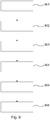
- a test extractor hood arrangement is equipped with sensors before the actual extractor hood 2 is manufactured in order to measure the delivery volume Q and the pressure difference p.
- the extractor hood 2 is operated in a step 902 as a circulating air device, that is to say without the piping 4, and as an exhaust air device, that is to say with piping 4 of different lengths, whereby the delivery volume Q and the pressure difference p are varied. At the same time, the delivery volume Q and the pressure difference p are measured. It is also possible to switch between the various torque-speed characteristics DK1 to DK3 by means of the control and evaluation device 21. The current torque-speed value pair M, n can be read out from the control and evaluation device 21.
- a respective measured delivery volume / pressure difference value pair p, Q is assigned to a respective torque / speed value pair M, n.
- the value pairs p, Q and M, n are then stored in a table in a step 903.
- the table is written to the memory 22 during the production of the extractor hood 2.
- an operating state of the extractor hood 2 can be determined as a function of a current torque / speed value pair M, n.
- the operating state is a circulating air or exhaust air operation UB, AB of the extractor hood 2, as will be explained in more detail on the basis of FIG Fig. 5 is explained.
- control and evaluation device 21 can use the current torque / speed value pair M, n to determine the delivery volume / pressure difference value pair p, Q or the exhaust air or recirculation mode AB, UB from the table.
- control and evaluation device 21 can determine the system characteristic curve AK1 to AK3 on the basis of the current delivery volume / pressure difference value pair p, Q. In particular, the control and evaluation device 21 can automatically determine the parameter “a” of the above equation.
- the control and evaluation device 21 can operate the fan motor 14 in a respective operating stage “1" to "4" in one Power or Boost mode - and not in normal mode - control automatically.
- Boost mode is based on Figure 7 explained in more detail. If, on the other hand, the control and evaluation device 21 determines that exhaust air operation of the extractor hood 2 is present, it can automatically control the fan motor 14 in normal mode in a respective operating level "1" to "4".
- a timer 31 is started when the extractor hood 1 or the control and evaluation device 21 detects the presence of a recirculation mode. As long as the timer falls below a predetermined value, that is to say a predetermined period of time, “Filter OK” is displayed on the TFT screen 25. However, if the timer exceeds the predetermined value, the TFT screen 25 can display “change filter”. The operator then knows that it is time to replace a circulating air filter, for example the grease filter 12.
- the extractor hood 2 or the control and evaluation device 21 is set up to automatically switch, for example, from the power mode to the boost mode when either the timer 31 has reached the predetermined value, that is the filter is full or the working point of the extractor hood 2 changes. This is also still based on Figure 5 explained in more detail.
- FIG. 4 now shows a selected delivery volume / pressure difference characteristic curve FK1. It is like in Figure 3 the pressure difference p is plotted as a function of the delivery volume Q.
- the delivery volume / pressure difference characteristic curve FK1 Figure 4 corresponds to the torque-speed characteristic curve DK1 Figure 2 .
- a delivery volume pressure difference characteristic curve FK1a corresponds to the torque / speed characteristic curve DK1a
- a delivery volume pressure difference characteristic curve FK1b corresponds to the torque / speed characteristic curve DK1b.
- the delivery volume pressure difference characteristic curve FK1, FK1a and FK1b each have different points of intersection with the system characteristic curve AK1 shown as an example, and accordingly different value pairs p, Q.
- Figure 5 shows further delivery volume / pressure difference characteristics, for example for the extractor hood 2 Figure 1 .
- a further torque-speed characteristic curve can be stored in the memory 22 of the control and evaluation device 21, which corresponds to the delivery volume-pressure difference characteristic curve FK1c.
- the control and evaluation device 21 can be set up to recognize whether the extractor hood 2 is being used in a circulating air or exhaust air mode UB, AB, as in connection with FIG Fig. 9 mentioned. In detail, this can be accomplished, for example, by assigning certain value pairs p, Q to a recirculation mode UB and other value pairs p, Q to an exhaust air mode AB in the table stored in the memory 22.
- the control and evaluation device 21 can then, for example, automatically decide that in the exhaust air mode AB it should use the fan motor 14 with the torque-speed characteristic curve DK1 corresponding to the delivery volume / pressure difference characteristic curve FK1 and, in the recirculation mode UB, the fan motor 14 with the delivery volume Pressure difference characteristic curve FK1c corresponding torque-speed characteristic curve (not shown) controls.
- the fan motor 14 automatically provides a higher pressure difference p in the recirculation mode UB, in which it is necessary to work against a higher air resistance due to the existing recirculation filter.
- control and evaluation device 21 can decide if it wants to shift the operating points AP1 to AP4 (see FIG Figure 3 ) determines over time that the grease filter 12 or the piping 4 is clogged.
- the control and evaluation device 21 can then control the fan motor 14 in, for example, the first operating stage "1" with the torque / speed characteristic curve corresponding to the delivery volume / pressure difference characteristic line FK1c - instead of the torque / speed characteristic line corresponding to the delivery volume / pressure difference characteristic line FK1.
- characteristic curve DK1 - in order to keep the delivery volume Q the same despite the higher air resistance.
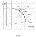
- FIG. 6 now shows the case that resonances occur at an operating point APR. This can be determined, for example, by testing the extractor hood 2 in connection with, for example, various pipework 4, as in connection with FIG Fig. 9 described. Provision can now be made for the operating point APR to be bypassed by changing in sections from the delivery volume pressure difference characteristic curve FK1 to a delivery volume pressure difference characteristic curve FK1d.
- the control and evaluation device 21 can be set up accordingly for this purpose.
- the delivery volume / pressure difference characteristic curve FK1d corresponds to a predetermined torque-speed characteristic curve, which, however, is not shown in any of the figures.
- Fig. 7 illustrates the possibility of providing a delivery volume pressure difference characteristic curve FK1e, which is shifted parallel to the delivery volume pressure difference characteristic curve FK1, for example in the direction of an increasing pressure difference p and an increasing delivery volume Q.
- the extractor hood is, for example, in operating level "1" (Delivery volume pressure difference characteristic curve FK1) and if the operator presses a boost button 26 of the extractor hood 2, the control and evaluation device 21 controls the fan motor 14 with one of the in Figure 2
- the torque-speed characteristic curve DK3 shown corresponds to the delivery volume pressure difference characteristic curve FK1e, so that, depending on the system characteristic curve AK2 or AK3, a significantly higher pressure difference (AK2) or a significantly higher delivery volume (AK3) results.
- a possible boost operating point is designated with AP1e.
- the control and evaluation device 21 starts a timer 27 in one embodiment. After a period of time stored on the timer 27 has elapsed, the control and evaluation device 21 switches back to the delivery volume / pressure difference characteristic curve FK1.
- the time span can be provided to be adjustable by the operator, for example by means of the touchscreen 25.
- Fig. 8 shows delivery volume / pressure difference characteristic curves in particular for a boost, power and eco mode according to a further embodiment.
- Fig. 7 shows Fig. 8 that a negative boost / delivery volume / pressure difference characteristic curve FK1g can also be provided, which is opposite to the delivery volume / pressure difference characteristic FK1g is shifted in parallel in the direction of lower pressure difference P and lower delivery volume Q.
- an eco or power mode can be configured differently for different pipework, ie system characteristics.
- the delivery volume pressure difference characteristics FK1f, FK1h correspond to the delivery volume pressure difference characteristics FK1a, FK1b Fig. 4 to the effect that they also have an intersection with the delivery volume / pressure difference characteristic curve FK1.
- the delivery volume pressure difference characteristic curve FK1h corresponding to an eco mode is provided convex and not concave like the delivery volume pressure difference characteristic curve FK1b.
- the control and evaluation device 21 can be set up to the fan motor 14 depending on a user input or automatically, for example depending on a currently available system characteristic curve AK2, AK3, which is determined by the control and evaluation device 21, with a the delivery volume / pressure difference characteristic curves FK1, FK1e, FK1f, FK1g or FK1h corresponding torque-speed characteristic.
- the user input and / or the currently available system characteristic AK2, AK3 is made available to the control and evaluation device 21 as one or more parameters.
- the activation as a function of a currently available system characteristic AK2, AK3 advantageously allows the operating points of the extractor hood 2 to be adapted to any pipework 4 that may be provided.
- the control and evaluation device 21 when the input device 25 recognizes a customer request for more delivery volume Q, can decide that a switch from normal mode (FK1) with an operating point AP1- 1 to a power mode (FK1f) with an operating point AP1f-1 yields too little additional delivery volume Q, and therefore switch to the boost mode (FK1e) with an operating point AP1e which has a high additional delivery volume Q.
- control and evaluation device 21 If, on the other hand, the control and evaluation device 21 detects that a system characteristic curve AK2 is present, it switches on with a customer request for more pressure difference p based on the normal mode (FK1) an operating point AP1-2 to power mode (FK1f) with an operating point AP1f-2 um, since a sufficiently high additional pressure difference p is provided here.
- FK1 normal mode
- FK1f power mode
Landscapes
- Engineering & Computer Science (AREA)
- Mechanical Engineering (AREA)
- General Engineering & Computer Science (AREA)
- Chemical & Material Sciences (AREA)
- Combustion & Propulsion (AREA)
- Ventilation (AREA)
- Control Of Positive-Displacement Air Blowers (AREA)
Description
- Die vorliegende Erfindung betrifft ein Verfahren zum Ermitteln eines Betriebszustands einer Dunstabzugshaubenanordnung.
- In Dunstabzugshauben wurden in der Vergangenheit aufgrund ihres kostengünstigen Aufbaus vorwiegend Gebläsemotoren in Form von Asynchronmotoren eingesetzt. Die Asynchronmotoren sind meist als Kondensator oder Spaltmotoren ausgeführt. Die Leistungsregelung erfolgt über Wicklungsabgriffe oder eine Phasenanschnittsteuerung. Bei solchen Asynchronmotoren ist die Drehmoment-Drehzahl-Kennlinie durch ihre Bauart vorgegeben und kann daher nur bedingt verändert werden.
- Dunstabzugshauben können in Küchen als Abluft- oder Umluftgeräte eingesetzt werden. Im Einsatz als Abluftgerät ist die Dunstabzugshaube mit einer Verrohrung beim Kunden verbunden, welche die von der Dunstabzugshaube gefilterte Luft aus der Küche heraus führt. Im Umluftbetrieb dagegen ist die Dunstabzugshaube direkt, also ohne Zwischenschaltung einer Verrohrung, mit dem Luftvolumen des Kücheninnenraums verbunden. Je nachdem, ob nun eine Verrohrung vorhanden ist bzw. wie diese ausgestaltet ist, ergibt sich für eine jeweilige Dunstabzugshaube eine individuelle Anlagen-Kennlinie. Ein Schnittpunkt der Anlagen-Kennlinie mit einer Fördervolumen-Druckdifferenz-Kennlinie der Dunstabzugshaube ergibt den Arbeitspunkt der Dunstabzugshaube. Der Arbeitspunkt meint dabei dasjenige Fördervolumen und diejenige Druckdifferenz, welches bzw. welche sich im Betrieb der Dunstabzugshaube einstellt. Die Fördervolumen-Druckdifferenz-Kennlinie steht dabei in einem festen Verhältnis mit der Drehmoment-Drehzahl-Kennlinie des Asynchronmotors. Mit anderen Worten variiert der Arbeitspunkt von Kunde zu Kunde je nach Einbausituation der Dunstabzugshaube, welche bei diesem jeweils vorliegt. Ein Hersteller von Dunstabzugshauben kennt die jeweilige Einbausituation beim Kunden nicht.
-
US 2012/0052792 A1 beschreibt eine Ventilationseinheit zum Installieren in einem Ventilationssystem. Die Ventilationseinheit umfasst einen Motor, der mit einem Ventilator gekoppelt ist, und eine Stromquelle. -
DE 10 2005 045 137 A1 beschreibt eine Lüftereinheit mit einer vorgegebenen künstlichen Kennlinie und ein Verfahren zu deren Betrieb. Die Lüftereinheit weist einen Elektromotor zum Antreiben eines Lüfterrads und eine Motorsteuerung auf. -
WO 2010/065793 A1 beschreibt ein System und ein Verfahren zum Steuern eine Abgasflussrate in einem Abgasventilationssystem einer Dunstabzugshaube. -
US 2010/092275 A1 beschreibt ein Haushaltsgerät mit einer Lüftergeschwind igkeitssteuerung. -
US 2011/0000652 A1 beschreibt eine Ventilationsvorrichtung und eine zugehörige elektronische Ausrüstung. Dieses Dokument offenbart den Oberbegriff des Anspruchs 1. -
EP 2 765 359 A2 beschreibt ein Verfahren zum Überwachen eines Luftstroms in einem Luftströmungskanal, in welchem ein von einem Lüftermotor angetriebenes Lüfterrad und wenigstens ein Luftfilter angeordnet sind, wobei bei dem Verfahren wenigstens ein Betriebsparameter oder eine Veränderung wenigstens eines Betriebsparameters des Lüftermotors erfasst wird. - Eine Aufgabe der vorliegenden Erfindung besteht darin, einen Betriebszustand einer Dunstabzugshaubenanordnung umfassend eine Dunstabzugshaube zu ermitteln.
- Demgemäß wird ein Verfahren zum Ermitteln eines Betriebszustands einer Dunstabzugshaubenanordnung umfassend eine Dunstabzugshaube bereitgestellt. Gemäß dem Verfahren wird der Betriebszustand in Abhängigkeit von einem Drehmoment-Drehzahl-Wertepaar eines Gebläsemotors der Dunstabzugshaube ermittelt.
- Bei dem Betriebszustand handelt es sich um einen Abluft- sowie einen Umluftbetrieb der Dunstabzugshaubenanordnung.
- Das Fördervolumen ist das Luftvolumen (inklusive eines etwaigen Wrasen), welches pro Zeiteinheit durch die Dunstabzugshaube und eine etwaige mit dieser verbundenen Verrohrung mittels des Gebläsemotors gefördert wird. Die Druckdifferenz meint vorliegend die Druckdifferenz, mit welcher der Gebläsemotor das Luftvolumen beaufschlagt. Die Druckdifferenz kann beispielsweise als Druckdifferenz zwischen einem Luftauslass der Dunstabzugshaube und einer Umgebung der Dunstabzugshaube gemessen werden. Die Druckdifferenz kann luftauslassseitig als statische Druckdifferenz in einer Druckkammer gemessen werden. Das Fördervolumen kann mittels einer der Druckkammer nachgeschalteten Venturidüse gemessen werden.
- Die Dunstabzugshaubenanordnung ist also dazu eingerichtet, einen Betriebszustand derselben beim Kunden selbst zu ermitteln. In Abhängigkeit von dem ermittelten Betriebszustand kann die Dunstabzugshaube dann insbesondere selbsttätig weitere Maßnahmen ergreifen, beispielsweise eine Drehmoment-Drehzahl-Kennlinie des Gebläsemotors anpassen, also insbesondere in einen Power-Modus oder Eco-Modus, wie nachfolgend noch näher erläutert wird, umschalten. Zusätzlich oder alternativ kann der Betriebszustand auch auf einer Anzeigeeinrichtung der Dunstabzugshaube angezeigt werden, beispielsweise in Form von Zahlen, Wörtern und/oder Symbolen.
- Erfindungsgemäß ist der Gebläsemotor als elektronisch kommutierter Synchronmotor ausgebildet, welcher mit Gleichstrom betrieben wird. Andere Bezeichnungen für solche Motoren sind BLDC (Bürstenloser Gleichstrommotor) oder EC-Motor (Elektronisch kommutierter Motor). Durch die elektronische Kommutierung weist der vorliegende Gebläsemotor eine hohe Flexibilität hinsichtlich seiner Regelungsmöglichkeiten auf. Insbesondere ist die Drehmoment-Drehzahl-Kennlinie und damit auch eine Fördervolumen-Druckdifferenz-Kennlinie der Dunstabzugshaubenanordnung - innerhalb gewisser Grenzen - frei wählbar und anpassbar. Insbesondere kann eine Steuereinrichtung der Dunstabzugshaube zur Ansteuerung des Gebläsemotors Software aufweisen, welche eine erste und zweite Drehmoment-Drehzahl-Kennlinie definiert. Die Drehmoment-Drehzahl-Kennlinien können auf einem Speicher der Steuereinrichtung abgespeichert sein. Insbesondere können die Drehmoment-Drehzahl-Kennlinien in Form von Wertetabellen abgespeichert sein. Die Steuereinrichtung kann beispielsweise in Form einer Rechnereinrichtung, insbesondere als Mikroprozessor, vorgesehen sein.
- Ein Parameter kann beispielsweise bei bekannter Netzspannung der von dem Gebläsemotor aufgenommene Strom sein. Eine Auswerteeinrichtung kann eine Funktion aufweisen, welche beispielsweise den Parameter in Form einer gemessenen Stromstärke auf einem Fördervolumen und/oder einer Druckdifferenz der Dunstabzugshaube abbildet. Die Funktion kann beispielsweise mittels einer Gleichung oder einer Tabelle auf der Auswerteeinrichtung, insbesondere auf einem Speicher derselben, abgelegt sein.
- Der Gebläsemotor ist ein elektrisch kommutierter Gleichstrommotor, welcher mittels einer Steuereinrichtung in Abhängigkeit von zumindest einer Drehmoment-Drehzahl-Kennlinie angesteuert wird. Der Betriebszustand wird in Abhängigkeit von zwei Parametern in Form eines Drehmoment-Drehzahl-Wertepaars der zumindest einen Drehmoment-Drehzahl-Kennlinie ermittelt. Vorteilhaft sind bei einem solchen elektrisch kommutierten Gleichstrommotor das aktuelle Drehmoment und die aktuelle Drehzahl jederzeit aus der Steuereinrichtung, insbesondere aus einem Speicher derselben, auslesbar. Ein jeweiliges Drehmoment-Drehzahl-Wertepaar kann dann über eine Funktion mittels einer Auswerteeinrichtung auf einen aktuellen Betriebszustand der Dunstabzugshaubenanordnung abgebildet werden. Auch hier kann als Funktion eine Gleichung oder eine Tabelle auf der Auswerteeinrichtung, insbesondere in einem Speicher derselben, abgelegt sein.
Dabei wird der Betriebszustand in Abhängigkeit von einer auf einem Speicher der Dunstabzugshaube gespeicherten Funktion und den zwei Parametern in Form eines Drehmoment-Drehzahl-Wertepaars ermittelt. Grundsätzlich kann die Funktion diskret oder kontinuierlich vorgesehen sein. Beispielsweise kann eine Tabelle oder Gleichung verwendet werden. Die Funktion kann auf einem Speicher einer Auswerteeinrichtung der Dunstabzugshaube abgelegt sein. - Gemäß einer weiteren Ausführungsform wird die Funktion im Herstellungsprozess der Dunstabzugshaube auf dem Speicher abgespeichert. Die Funktion wird also vor Auslieferung der Dunstabzugshaube an den Kunden auf dem Speicher abgespeichert. Beispielsweise kann die Funktion auf dem Speicher abgespeichert werden, woraufhin der Speicher in der Dunstabzugshaube verbaut wird. Die Funktion steht dann im Betrieb der Dunstabzugshaube beim Kunden zur Verfügung.
- Gemäß einer weiteren Ausführungsform wird die Funktion vor dem Herstellungsprozess der Dunstabzugshaube mittels einer Test-Dunstabzugshaubenanordnung ermittelt, deren Fördervolumen und/oder Druckdifferenz variiert wird. Mit anderen Worten wird die Funktion also dadurch bestimmt, dass eine Dunstabzugshaube in einer Testumgebung mit keiner Verrohrung (Umluftbetrieb) sowie Verrohrungen unterschiedlicher Länge (Abluftbetrieb) verbunden wird. Hierbei werden dann beispielsweise mittels Sensoren das Fördervolumen und/oder die Druckdifferenz erfasst und dem zumindest einen Parameter zugeordnet. Beispielsweise können das Fördervolumen und/oder die Druckdifferenz einer dem Gebläsemotor zugeführten Stromstärke oder einem Drehmoment-Drehzahl-Wertepaar des Gebläsemotors zugeordnet werden. Drehmoment und Drehzahl können dabei im Falle eines elektrisch kommutierten Gleichstrommotors aus der entsprechenden Steuereinrichtung ausgelesen werden.
- Gemäß einer weiteren Ausführungsform wird der Betriebszustand im bestimmungsgemäßen Einsatz der Dunstabzugshaube ermittelt. Beispielsweise werden das Fördervolumen und/oder die Druckdifferenz (und damit der Arbeitspunkt und gegebenenfalls die Anlagen-Kennlinie) mittels des Verfahrens vor Ort beim Kunden ermittelt. Damit kann die jeweils vorliegende Einbausituation, beispielsweise damit auch eine Verrohrungslänge einer mit der Dunstabzugshaube verbundenen Verrohrung, ermittelt werden.
- Gemäß einer weiteren Ausführungsform umfasst die Dunstabzugshaubenanordnung ausschließlich die Dunstabzugshaube oder die Dunstabzugshaube und eine mit dieser luftleitend verbundene Verrohrung. In dem Fall, dass die Dunstabzugshaube als Umluftgerät betrieben wird, ist keine Verrohrung vorgesehen, so dass die Dunstabzugshaubenanordnung ausschließlich die Dunstabzugshaube umfasst. In dem Fall, dass die Dunstabzugshaube als Abluftgerät betrieben wird, umfasst die Dunstabzugshaubenanordnung die Dunstabzugshaube sowie eine mit dieser luftleitend verbundene Verrohrung. Die Verrohrung kann unterschiedliche Längen und/oder Durchmesser und damit einen variablen Luftwiderstand aufweisen.
- Gemäß einer weiteren Ausführungsform wird der Betriebszustand auf einer Anzeigeeinrichtung der Dunstabzugshaube dargestellt. Die Anzeigeeinrichtung kann beispielsweise als Bildschirm, insbesondere TFT-Bildschirm und/oder Touchscreen, ausgebildet sein. Die Anzeigeeinrichtung kann zur Anzeige des aktuellen Fördervolumens, beispielsweise in Form von Kubikmetern pro Stunde oder in Form eines Balkens, dessen Länge von dem Betrag des Fördervolumens abhängt, eingerichtet sein.
- Gemäß einer weiteren Ausführungsform wird, wenn ermittelt wird, dass sich die Dunstabzugshaube in einem Umluftbetrieb befindet, ein Timer (Zeitgeber) gestartet, und/oder, wenn der Timer einen vorbestimmten Wert erreicht hat, dies einer Bedienerperson mittels einer Ausgabeeinrichtung mitgeteilt. Beispielsweise kann nur der Timer gestartet werden und dieser der Bedienerperson auf eine Anzeigeeinrichtung angezeigt werden. Beispielsweise kann der Timer in Form eines Balkens angezeigt werden, dessen Länge von der verstrichenen Zeit abhängt. Die Bedienerperson kann dann selbst entscheiden, wann sie einen Umluftfilter der Dunstabzugshaube austauscht. Alternativ kann, wie vorstehend bereits beschrieben, der Bedienerperson über eine Ausgabeeinrichtung mitgeteilt werden, dass der Umluftfilter auszutauschen ist, wenn der Timer einen vorbestimmten Wert erreicht. Beispielsweise kann die Ausgabeeinrichtung in Form einer Anzeigeeinrichtung, beispielsweise TFT-Bildschirms oder Touchscreens, oder eines Lautsprechers zur Erzeugung eines Warntons ausgebildet sein. Auf der Anzeigeeinrichtung kann beispielsweise ein Filterwechselsymbol angezeigt werden, wenn der Timer den vorbestimmten Wert erreicht hat. Ein Umluftfilter, bspw. ein Aktivkohlefilter, ist ein solcher Filter, welcher im Umluftbetrieb in der Dunstabzugshaube vorgesehen wird, um eine bessere Reinigung der zu filternden Luft zu ermöglichen. Bei einem Abluftbetrieb ist ein solcher Filter nicht vorgesehen. Da der Filter jedoch die Anlagen-Kennlinie beeinflusst, kann vorgesehen sein, dass die Steuereinrichtung den Gebläsemotor mit einer an den Umluft- oder Abluftbetrieb angepassten Drehmoment-Drehzahl-Kennlinie ansteuert.
- Gemäß einer weiteren Ausführungsform wird der elektronisch kommutierte Gleichstrommotor in Abhängigkeit von dem ermittelten Betriebszustand mit einer ersten oder zweiten Drehmoment-Drehzahl-Kennlinie angesteuert. Somit kann eine Drehmoment-Drehzahl-Kennlinie an einen jeweiligen Betriebszustand angepasst werden.
- Die erste und zweite Drehmoment-Drehzahl-Kennlinie können einen gemeinsamen Punkt aufweisen. Damit, dass die Drehmoment-Drehzahl-Kennlinien zumindest einen gemeinsamen Punkt aufweisen, ist gemeint, dass die Drehmoment-Drehzahl-Kennlinien in einem ersten Bereich (in zumindest einem Punkt) ein identisches Drehmoment-Drehzahl-Wertepaar oder einen identischen Verlauf und in einem zweiten Bereich ein unterschiedliches Drehmoment-Drehzahl-Wertepaar oder einen unterschiedlichen Verlauf aufweisen. Die erste Drehmoment-Drehzahl-Kennlinie kann beispielsweise einem Normal-Modus einer ersten von einer Bedienerperson auswählbaren Betriebsstufe der Dunstabzugshaube zugeordnet sein. Die zweite Drehmoment-Drehzahl-Kennlinie kann einem Power-Modus der Dunstabzugshaube in der ersten Betriebsstufe zugeordnet sein. Der Power-Modus kann einem Betrieb der Dunstabzugshaube entsprechen, in welchem das Fördervolumen gegenüber dem Normal-Modus erhöht ist. Erkennt die Dunstabzugshaube beispielsweise, dass ein Umluftbetrieb vorliegt, bei welchem ein Filter, insbesondere ein Aktivkohlefilter, eingesetzt wird, so kann sie selbsttätig, also ohne Benutzerinteraktion, den Power-Modus einschalten. Die Steuer- und Auswerteeinrichtung kann hierzu entsprechend ausgebildet sein. Damit weist die Dunstabzugshaube beispielsweise in jeder von vier Betriebsstufen eine verbesserte Absaugung gegenüber einem jeweiligen Normalmodus auf. Tatsächlich wird so ein Minus an Absaugleistung in dem Umluftbetrieb ausgeglichen, so dass jeder Kunde, egal ob er die Dunstabzugshaube im Umluft- oder im Ablaufbetrieb zu Hause einsetzt, eine zufriedenstellende Absaugung vorfindet.
- Alternativ kann der elektronisch kommutierte Gebläsemotor von einer Steuereinrichtung der Dunstabzugshaube mit einer ersten, zweiten oder dritten Drehmoment-Drehzahl-Kennlinie angesteuert werden. Die erste und dritte Drehmoment-Drehzahl-Kennlinie sind jeweils mittels einer Eingabeeinrichtung von einer Bedienerperson anwählbar. Die Steuereinrichtung ist weiter dazu ausgebildet, in Abhängigkeit von dem ermittelten Betriebszustand den Gebläsemotor ausgehend von der ersten oder dritten Drehmoment-Drehzahl-Kennlinie mit der zweiten Drehmoment-Drehzahl-Kennlinie anzusteuern. Mit anderen Worten kann eine Bedienerperson die Dunstabzugshaube zwischen einer ersten Betriebsstufe (erste Drehmoment-Drehzahl-Kennlinie) und einer zweiten Betriebsstufe (zweite Drehmoment-Drehzahl-Kennlinie) beispielsweise mittels Knopfdruck umschalten. Das Umschalten von der ersten Drehmoment-Drehzahl-Kennlinie auf die zweite Drehmoment-Drehzahl-Kennlinie nimmt die Steuereinrichtung dann selbsttätig in Abhängigkeit von dem ermittelten Betriebszustand vor. Auf diese Weise kann beispielsweise auf eine jeweils beim Kunden vorliegende Anlagen-Kennlinie flexibel reagiert werden.
- Gemäß einer Ausführungsform weisen die erste, zweite und/oder dritte Drehmoment-Drehzahl-Kennlinie eine Asynchroncharakteristik auf. Die Asynchroncharakteristik entspricht also im Grundsatz einer Drehmoment-Drehzahl-Kennlinie, welche der Form eines liegenden "S" entspricht. Mit anderen Worten umfasst die Asynchroncharakteristik der Drehmoment-Drehzahl-Kennlinie ein Tal, welches in Richtung steigender Drehzahl von einem Berg gefolgt. Mit zunehmender Annäherung an die Nenn-Drehzahl sinkt das Drehmoment asymptotisch gegen Null ab.
- Bei der ersten Drehmoment-Drehzahl-Kennlinie kann es sich beispielsweise um einen Normalmodus einer ersten Betriebsstufe der Dunstabzugshaube handeln. Die zweite Drehmoment-Drehzahl-Kennlinie kann einem Power-Modus, Eco-Modus oder Boost-Modus der Dunstabzugshaube entsprechen.
- Gemäß einer weiteren Ausführungsform ist die zweite Drehmoment-Drehzahl-Kennlinie gewählt, um Resonanzeffekte der Dunstabzugshaubenanordnung bei dem ermittelten Betriebszustand zu vermeiden.
- Weiterhin wird eine Dunstabzugshaubenanordnung mit einer Dunstabzugshaube, welche einen Gebläsemotor sowie eine Auswerteeinrichtung umfasst, bereitgestellt. Die Auswerteeinrichtung ist dazu eingerichtet, einen Betriebszustand der Dunstabzugshaubenanordnung in Abhängigkeit von Drehmoment und Drehzahl des Gebläsemotors zu ermitteln.
- Die Auswerteeinrichtung kann als Rechnereinrichtung, insbesondere Mikroprozessor, ausgebildet sein. Die Dunstabzugshaube kann ferner eine Steuereinrichtung und/oder eine Anzeigeeinrichtung aufweisen, wie vorstehend beschrieben. Die Steuer- und Auswerteeinrichtung können in eine Rechnereinrichtung integriert sein.
Die Dunstabzugshaube ist bevorzugt als Haushaltsgerät ausgebildet. - Die in Bezug auf das Verfahren beschriebenen Ausführungsbeispiele gelten für die Dunstabzugshaubenanordnung entsprechend.
Es sei angemerkt, dass vorliegend die Bezeichnungen "erste", "zweite" usw. Drehmoment-Drehzahl-Kennlinie/Fördervolumen-Druckdifferenz-Kennlinie usw. verwendet werden. Dies dient jedoch lediglich der besseren Unterscheidung. Eine Änderung der Bezeichnung, beispielsweise "vierte" statt "zweite", ist daher bei Bedarf jederzeit möglich. - Weitere vorteilhafte Ausgestaltungen der Erfindung sind Gegenstand der Unteransprüche.
- Im Weiteren wird die Erfindung anhand von bevorzugten Ausführungsformen unter Bezugnahme auf die beigelegten Figuren näher erläutert.
Es zeigen dabei: -
Fig. 1 : schematisch eine Dunstabzugshaubenanordnung gemäß einer Ausführungsform; -
Fig. 2 : Drehmoment-Drehzahl-Kennlinien gemäß einer Ausführungsform; -
Fig. 3 : Fördervolumen-Druckdifferenz-Kennlinien sowie Anlagen-Kennlinien gemäß einer Ausführungsform; -
Fig. 4 : Fördervolumen-Druckdifferenz-Kennlinien für einen Power- und Eco-Modus gemäß einer Ausführungsform; -
Fig. 5 : Fördervolumen-Druckdifferenz-Kennlinien für einen Umluft- und Abluftbetrieb gemäß einer Ausführungsform; -
Fig. 6 : Fördervolumen-Druckdifferenz-Kennlinien zur Vermeidung von Resonanz gemäß einer Ausführungsform; -
Fig. 7 : Fördervolumen-Druckdifferenz-Kennlinien für einen Boost-Modus gemäß einer Ausführungsform; -
Fig. 8 : Fördervolumen-Druckdifferenz-Kennlinien für einen Boost,- Power- und Eco-Modus gemäß einer weiteren Ausführungsform; und -
Fig. 9 : ein Ablaufdiagramm gemäß einer Ausführungsform. - In den Figuren bezeichnen gleiche Bezugszeichen gleiche oder funktionsgleiche Komponenten, soweit nichts anderes angegeben ist.
-
Figur 1 zeigt schematisch eine Dunstabzugshaubenanordnung 1 gemäß einer Ausführungsform. - Die Dunstabzugshaubenanordnung 1 umfasst eine Dunstabzugshaube 2, welche oberhalb einer Kochstelle 3 in einer Küche angeordnet ist. Die Dunstabzugshaube 2 kann beispielsweise als Haube oder Esse ausgeführt sein. Die Dunstabzugshaube 2 kann hierzu - wie auch eine Verrohrung 4 - an einer Gebäudewand 5 der Küche befestigt sein. Die Dunstabzugshaube 2 fördert im Betrieb Wrasen 6 von oberhalb der Kochstelle 3 über einen Lufteinlass 7 zu einem Luftauslass 11 derselben. Der Luftauslass 11 ist über die Verrohrung 4 mit der Umgebung außerhalb der Küche luftleitend verbunden. Alternativ kann die Dunstabzugshaube - wie später noch näher erläutert wird - als Umluftgerät vorgesehen sein, wobei der Luftauslass 11 mit dem Innenraum 10 der Küche luftleitend verbunden ist.
- Die Dunstabzugshaube 2 umfasst ein Lüfterrad 13. Das Lüfterrad 13 wird von einem elektronisch kommutierten Gebläsemotor 14 angetrieben sein. Das Lüfterrad 13 bildet mit einem dieses umgebenden spiralförmigen Gehäuse 15 ein Radialgebläse 16 aus, welches den Wrasen 6 durch einen Fettfilter 12 im Bereich des Lufteinlasses 7 saugt und durch den Luftauslass 11 ausstößt. Dabei muss das Radialgebläse 16 den internen Luftwiderstand der Dunstabzugshaube 2, welcher sich insbesondere aufgrund des Radialgebläses 16 selbst sowie einer internen Verrohrung 17 ergibt, überwinden. Weiterhin muss das Radialgebläse 16 den Luftwiderstand der Verrohrung 4 (soweit diese vorhanden ist) überwinden, um die Luft nach außerhalb des Innenraums 10 der Küche zu fördern. Der interne Luftwiderstand der Dunstabzugshaube 2 ergibt eine Anlagen-Kennlinie derselben im Umluftbetrieb. Die Summe aus dem internen Luftwiderstand der Dunstabzugshaube 2 und dem Luftwiderstand der Verrohrung 4 ergibt die Anlagen-Kennlinie im Abluftbetrieb. Beispielhafte Anlagen-Kennlinien sind in
Figur 3 gezeigt und dort mit AK1, AK2 und AK3 bezeichnet. - Nun zurückkehrend zu
Figur 1 ist dort weiter gezeigt, dass die Dunstabzugshaube 2 eine Steuer- und Auswerteeinrichtung 21 umfasst, welche den Gebläsemotor 14 ansteuert. Die Steuer- und Auswerteeinrichtung 21 ist beispielsweise als Mikroprozessor ausgebildet und umfasst einen Speicher 22. Auf dem Speicher 22 sind in Form von Software inFigur 2 gezeigte Drehmoment-Drehzahl-Kennlinien abgelegt. -
Figur 2 zeigt eine erste Drehmoment-Drehzahl-Kennlinie DK1, eine zweite Drehmoment-Drehzahl-Kennlinie DK1a, eine dritte Drehmoment-Drehzahl-Kennlinie DK1b, eine vierte Drehmoment-Drehzahl-Kennlinie DK2, und eine fünfte Drehmoment-Drehzahl-Kennlinie DK3. Das Drehmoment M des Gebläsemotors 14 wird dabei als Funktion seiner Drehzahl n dargestellt. - Die Drehmoment-Drehzahl-Kennlinien DK1 bis DK3 weisen jeweils eine Asynchroncharakteristik auf. Das heißt, ihre Form entspricht einem liegenden "S". Weiter heißt dies, dass jede der Drehmoment-Drehzahl-Kennlinien DK1 bis DK3 ein Anzugsmoment MA1, MA2, MA3, ein Sattelmoment MS1, MS2, MS3, ein Kippmoment MK1, MK1a, MK1b, MK2, MK3 sowie eine Nenn-Drehzahl nN umfasst. Das Anzugsmoment MA1, MA2, MA3 entspricht dem Drehmoment des Gebläsemotors 14 bei einer Drehzahl n=0. Ausgehend vom Anzugsmoment MA1, MA2, MA3 sinkt das Drehmoment bis zum Sattelmoment MS1, MS2, MS3 mit zunehmender Drehzahl n ab und steigt hiernach wieder, und erreicht sein Maximum MK1, MK1a, MK1b, MK2, MK3. Hiernach sinkt das Drehmoment M wieder ab und nähert sich hin zur Nenn-Drehzahl nN asymptotisch gegen Null an. Ein Arbeitsbereich, in welchem der Gebläsemotor 14 typischerweise von der Steuer- und Auswerteeinrichtung 21 im Betrieb der Dunstabzugshaube 2 angesteuert wird, ist mit AH bezeichnet.
- Die Drehmoment-Drehzahl-Kennlinien DK1, DK1a, DK1b weisen einen abschnittsweise identischen Verlauf auf. So sind das Anzugs- und das Sattelmoment MA1, MS1 für die Drehmoment-Drehzahl-Kennlinien DK1 bis DK1b identisch. Lediglich hinsichtlich ihres Kippmoments MK1, MK1a und MK1b unterscheiden sie sich. So liegt das Kippmoment MK1a über dem Kippmoment MK1 und das Kippmoment MK1b unter dem Kippmoment MK1. Die Drehmoment-Drehzahl-Kennlinie DK2 verläuft dagegen parallel zur Drehmoment-Drehzahl-Kennlinie DK1 und ist bezüglich dieser nach oben verschoben, also durchwegs durch ein höheres Drehmoment M gekennzeichnet. Folglich liegt das Kippmoment MK2 über MK1a, MK1 und MK1b. Die Drehmoment-Drehzahl-Kennlinie DK3 verläuft ebenfalls parallel zur Drehmoment-Drehzahl-Kennlinie DK1 und zwischen dieser und der Drehmoment-Drehzahl-Kennlinie DK2.
- Die Drehmoment-Drehzahl-Kennlinie DK1 ist beispielsweise einem Normal-Modus einer ersten Betriebsstufe der Dunstabzugshaube 2 und die Drehmoment-Drehzahl-Kennlinie DK2 einem Normal-Modus einer zweiten Betriebsstufe der Dunstabzugshaube 2 zugeordnet. Es können auch weitere Betriebsstufen, beispielsweise eine dritte und eine vierte Betriebsstufe vorgesehen sein, welche in
Figur 1 gezeigt sind. Selbstverständlich ist auch ein Aus-Zustand der Dunstabzugshaube bzw. des Gebläsemotors 14 vorgesehen. Beispielsweise kann die Dunstabzugshaube 2, wie inFigur 1 gezeigt, Knöpfe 23 umfassen, mittels welchen der Aus-Zustand "0" und die erste bis vierte Betriebsstufe "1", "2", "3", "4" anwählbar sind. In Abhängigkeit von einem aktuell gedrückten Knopf 23 steuert die Steuer- und Auswerteeinrichtung 21 den Gebläsemotor 14 nicht (Aus-Zustand) oder mit der ersten Drehmoment-Drehzahl-Kennlinie DK1 (erste Betriebsstufe) oder der vierten Drehmoment-Drehzahl-Kennlinie DK2 (zweite Betriebsstufe) oder einer weiteren Drehmoment-Drehzahl-Kennlinie (dritte und vierte Betriebsstufe) an. Anstelle der Knöpfe 23 könnte auch eine sonstige Eingabeeinrichtung vorgesehen sein. - Die zweite Drehmoment-Drehzahl-Kennlinie DK1a entspricht beispielsweise einem Power-Modus und die dritte Drehmoment-Drehzahl-Kennlinie DK1b einem Eco-Modus, wie nachfolgend noch näher erläutert wird. Befindet sich nun die Dunstabzugshaube 2 beispielsweise im Normal-Modus (DK1) des ersten Betriebszustands "1", so kann eine Bedienerperson die Dunstabzugshaube 2 durch Betätigen einer Eingabeeinrichtung beispielsweise in Form eines Knopfes 24 aus dem Normal-Modus entsprechend der ersten Drehmoment-Drehzahl-Kennlinie DK1 in den Power-Modus entsprechend der Drehmoment-Drehzahl-Kennlinie DK1a oder den Eco-Modus entsprechend der Drehmoment-Drehzahl-Kennlinie DK1b umschalten. Beispielsweise kann ein Umschalten in den Power-Modus erfolgen, wenn ein höherer Fördervolumenstrom gewünscht ist. Ein Umschalten in den Eco-Modus kann erfolgen, wenn eine Geräuschbildung durch die Dunstabzugshaube 2 reduziert oder Energie gespart werden soll. Das Umschalten in den Eco- und Power-Modus kann auch erfolgen, wenn die Dunstabzugshaube 2 in dem Normal-Modus der zweiten, dritten oder vierten Betriebsstufe "2" "3" "4" betrieben wird. Die Drehmoment-Drehzahl-Kennlinien DK2a und DK2b illustrieren beispielhaft den der zweiten Betriebsstufe "2" zugeordneten Power- bzw. Eco-Modus. Das Kippmoment MK2a liegt dann über dem Kippmoment MK2 und das Kippmoment MK2b unterhalb dem Kippmoment MK2.
- Ferner kann die Dunstabzugshaube 2 eine Anzeigeeinrichtung beispielsweise in Form eines TFT-Bildschirms 25 umfassen, auf welchem angezeigt wird, in welcher Betriebsstufe sich die Dunstabzugshaube 2 befindet. Weiter kann der TFT-Bildschirm 25 anzeigen, ob sich die Dunstabzugshaube 2 in dem Normal-Modus, Power-Modus oder dem Eco-Modus befindet. Noch weiterhin kann der TFT-Bildschirm 25 ein von der Dunstabzugshaube 2 aktuell gefördertes Fördervolumen beispielsweise in Kubikmeter pro Stunde anzeigen. Der TFT-Bildschirm 25 kann von der Steuer- und Auswerteeinrichtung 21 entsprechend angesteuert werden. Die Eingabeeinrichtungen 23, 24 könnten auch in die Anzeigeeinrichtung 25 integriert sein, indem diese beispielsweise als Touchscreen ausgebildet ist, der gleichzeitig auch Eingabeeinrichtung für Benutzerbefehle ist.
- Nachfolgend wird anhand von
Figur 3 der Zusammenhang zwischen einer Druckdifferenz p und einem Fördervolumen Q für unterschiedliche Anlagen-Kennlinien AK1 bis AK3 sowie unterschiedliche Fördervolumen-Druckdifferenz-Kennlinien FK1 bis FK4 näher erläutert. -
Figur 3 zeigt dabei die Druckdifferenz p als Funktion des Fördervolumens Q. Die Druckdifferenz p bezeichnet dabei eine Druckdifferenz zwischen dem Umgebungsdruck in dem Kücheninnenraum 10 (sieheFigur 1 ) und einem Druck, welcher beispielsweise im Luftauslass 11 der Dunstabzugshaube 2 gemessen wird. Das Fördervolumen Q meint ein pro Zeiteinheit gefördertes Luftvolumen, beispielsweise in Kubikmeter pro Stunde. - Jeder der Drehmoment-Drehzahl-Kennlinien aus
Figur 2 ist eine Fördervolumen-Druckdifferenz-Kennlinie inFigur 3 zugeordnet. So entspricht beispielsweise die Drehmoment-Drehzahl-Kennlinie DK1 der Fördervolumen-Druckdifferenz-Kennlinie FK1 und die Drehmoment-Drehzahl-Kennlinie DK2 der Fördervolumen-Druckdifferenz-Kennlinie FK2. Die den Fördervolumen-Druckdifferenz-Kennlinien FK3 und FK4 entsprechenden Drehmoment-Drehzahl-Kennlinien sind inFigur 2 nicht gezeigt. Jedes Wertepaar einer jeweiligen Drehmoment-Drehzahl-Kennlinie ausFigur 2 hat eine Entsprechung auf einer jeweiligen Fördervolumen-Druckdifferenz-Kennlinie ausFigur 3 . - Wird nun die Dunstabzugshaube 2 beispielsweise als Umluftgerät betrieben und mittels eines Knopfs 23 die erste Betriebsstufe "1" im Normal-Modus und damit die erste Fördervolumen-Druckdifferenz-Kennlinie FK1 angewählt, so ergibt sich ein Arbeitspunkt AP1, an welchem die Dunstabzugshaube 2 operiert. Der Arbeitspunkt AP1 ist ein Schnittpunkt zwischen der Fördervolumen-Druckdifferenz-Kennlinie FK1 und der Anlagen-Kennlinie AK1. Die Form der Anlagen-Kennlinien AK1 bis AK3 entspricht einer Parabel, welche durch die folgende Gleichung gekennzeichnet ist:

- So kann beispielsweise die Anlagen-Kennlinie AK2 eine Verrohrung 4 mit einer ersten Länge und die Anlagen-Kennlinie AK3 eine Verrohrung 4 mit einer zweiten Länge darstellen, wobei die zweite Länge größer als die erste Länge und entsprechend auch der Luftwiderstand höher ist. Die Arbeitspunkte AP1, AP2, AP3 und AP4 ergeben sich, indem zwischen den Betriebsstufen "1" bis "4" im Normal-Modus umgeschaltet wird, siehe
Figur 2 . - Es kann vorgesehen sein, dass insbesondere die in
Figur 3 und4 gezeigten Fördervolumen-Druckdifferenz-Kennlinien FK1 bis FK4 beispielsweise in Form einer Tabelle auf dem Speicher 22 der Steuer- und Auswerteeinrichtung 21 abgelegt sind. Weiterhin können in der Tabelle einem jeweiligen Fördervolumen-Druckdifferenz-Wertepaar p, Q zugeordnete Drehmoment-Drehzahl-Wertepaare M, n abgelegt sein. - Im Zusammenhang mit dem Ablaufdiagramm aus
Figur 9 wird nachfolgend erläutert, wie die Tabelle erzeugt werden kann. Erfindungsgemäß ist anstelle der Tabelle auch eine andere Funktion, beispielsweise eine Gleichung, auf dem Speicher 22 der Steuer- und Auswerteeinrichtung 21 abgelegt, welche eine Zuordnung zwischen einem jeweiligen Fördervolumen-Druckdifferenz-Wertepaare p, Q und einem Drehmoment-Drehzahl-Wertepaar M, n schafft. - In einem ersten Schritt 901 wird eine Test-Dunstabzugshaubenanordnung vor der Herstellung der eigentlichen Dunstabzugshaube 2 mit Sensoren ausgestattet, um das Fördervolumen Q und die Druckdifferenz p zu messen.
- Hiernach wird die Dunstabzugshaube 2 in einem Schritt 902 als Umluftgerät, das heißt ohne die Verrohrung 4, und als Abluftgerät, das heißt mit Verrohrungen 4 unterschiedlicher Länge, betrieben werden, wodurch das Fördervolumen Q und die Druckdifferenz p variiert wird. Gleichzeitig werden das Fördervolumen Q und die Druckdifferenz p gemessen. Weiterhin kann zwischen den verschiedenen Drehmoment-Drehzahl-Kennlinien DK1 bis DK3 mittels der Steuer- und Auswerteeinrichtung 21 umgeschaltet werden. Das jeweils aktuelle Drehmoment-Drehzahl-Wertepaar M, n kann dabei aus der Steuer- und Auswerteeinrichtung 21 ausgelesen werden.
- Ein jeweiliges gemessenes Fördervolumen-Druckdifferenz-Wertepaar p, Q wird einem jeweiligen Drehmoment-Drehzahl-Wertepaar M, n zugeordnet. Die Wertepaare p, Q bzw. M, n werden sodann in einer Tabelle in einem Schritt 903 abgelegt.
- Zusätzlich zu den Fördervolumen-Druckdifferenz-Wertepaaren kann in die Tabelle geschrieben werden, ob ein Abluft- oder Umluftbetrieb der Dunstabzugshaube 2 vorliegt.
- In einem weiteren Schritt 904 wird bei der Herstellung der Dunstabzugshaube 2 die Tabelle auf den Speicher 22 geschrieben.
- Somit kann in einem Schritt 905 bei bestimmungsgemäßen Einsatz der Dunstabzugshaube 2 in Abhängigkeit von einem aktuellen Drehmoment-Drehzahl-Wertepaar M, n ein Betriebszustand der Dunstabzugshaube 2 ermittelt werden. Bei dem Betriebszustand handelt es sich um einen Umluft- oder Abluftbetrieb UB, AB der Dunstabzugshaube 2, wie noch näher anhand von
Fig. 5 erläutert wird. - Dazu kann die Steuer- und Auswerteeinrichtung 21 unter Verwendung des aktuellen Drehmoment-Drehzahl-Wertepaars M, n das Fördervolumen-Druckdifferenz-Wertepaar p, Q oder den Abluft- oder Umluftbetrieb AB, UB aus der Tabelle ermitteln.
- In einem Schritt 906 kann die Steuer- und Auswerteeinrichtung 21 auf Basis des aktuellen Fördervolumen-Druckdifferenz-Wertepaars p, Q die Anlagen-Kennlinie AK1 bis AK3 ermitteln. Insbesondere kann die Steuer- und Auswerteeinrichtung 21 den Parameter "a" der vorstehenden Gleichung automatisiert ermitteln.
- Stellt die Dunstabzugshaube 2 nun beispielsweise bei einer ersten Inbetriebnahme derselben beim Kunden (also ein erstes Anschalten) fest, dass ein Umluftbetrieb vorliegt, so kann die Steuer- und Auswerteeinrichtung 21 den Gebläsemotor 14 in einer jeweiligen Betriebsstufe "1" bis "4" in einem Power- oder Boost-Modus - und nicht in dem Normal-Modus - selbsttätig ansteuern. Der Boost-Modus wird anhand von
Figur 7 näher erläutert. Stellt die Steuer- und Auswerteeinrichtung 21 dagegen fest, dass ein Abluftbetrieb der Dunstabzugshaube 2 vorliegt, so kann sie den Gebläsemotor 14 im Normal-Modus in einer jeweiligen Betriebsstufe "1" bis "4" selbsttätig ansteuern. - Weiterhin kann vorgesehen sein, dass ein Timer 31 gestartet wird, wenn die Dunstabzugshaube 1 bzw. die Steuer- und Auswerteeinrichtung 21 das Vorliegen eines Umluftbetriebs detektiert. Solange der Timer einen vorbestimmten Wert, das heißt eine vorbestimmte Zeitspanne, unterschreitet, wird auf dem TFT-Bildschirm 25 angezeigt "Filter OK". Überschreitet der Timer allerdings den vorbestimmten Wert, so kann der TFT-Bildschirm 25 anzeigen "Filter wechseln". Die Bedienerperson weiß dann, dass es Zeit ist, einen Umluftfilter, beispielsweise den Fettfilter 12, auszutauschen.
- Alternativ oder zusätzlich kann vorgesehen sein, dass die Dunstabzugshaube 2 bzw. die Steuer- und Auswerteeinrichtung 21 dazu eingerichtet ist, automatisch beispielsweise von dem Power-Modus auf den Boost-Modus umzuschalten, wenn, entweder der Timer 31 den vorbestimmten Wert erreicht hat, also der Filter voll ist, oder sich der Arbeitspunkt der Dunstabzugshaube 2 verändert. Dies wird auch noch anhand von
Figur 5 näher erläutert. -
Figur 4 zeigt nun eine ausgewählte Fördervolumen-Druckdifferenz-Kennlinie FK1. Dabei ist wie inFigur 3 die Druckdifferenz p als Funktion des Fördervolumens Q aufgetragen. Die Fördervolumen-Druckdifferenz-Kennlinie FK1 ausFigur 4 entspricht der Drehmoment-Drehzahl-Kennlinie DK1 ausFigur 2 . Eine Fördervolumen-Druckdifferenz-Kennlinie FK1a entspricht der Drehmoment-Drehzahl-Kennlinie DK1a und eine Fördervolumen-Druckdifferenz-Kennlinie FK1b der Drehmoment-Drehzahl-Kennlinie DK1b. Die Fördervolumen-Druckdifferenz-Kennlinie FK1, FK1a und FK1b weisen jeweils unterschiedliche Schnittpunkte mit der beispielhaft dargestellten Anlagen-Kennlinie AK1 auf, und entsprechend damit insoweit jeweils unterschiedlichen Wertepaaren p, Q. Diese Arbeitspunkte der Dunstabzugshaube 2 sind mit AP1, AP1a und AP1b bezeichnet. InFigur 4 ist zu erkennen, dass die erste und zweite Fördervolumen-Druckdifferenz-Kennlinie FK1, FK1a einen konvexen Verlauf und die dritte Fördervolumen-Druckdifferenz-Kennlinie FK1b einen konkaven Verlauf aufweist. - Anhand von
Figur 4 wird deutlich, dass in der ersten Betriebsstufe "1" das Umschalten zwischen dem Normal-Modus (FK1), dem Power-Modus (FK1a) und dem Eco-Modus (FK1b) zu unterschiedlichen Fördervolumina Q durch die Dunstabzugshaube 2 führt. Gleichzeitig unterscheiden sich auch die Geräuschbildung sowie andere Parameter. -
Figur 5 zeigt weitere Fördervolumen-Druckdifferenz-Kennlinien beispielsweise für die Dunstabzugshaube 2 ausFigur 1 . - Beispielsweise kann auf dem Speicher 22 der Steuer- und Auswerteeinrichtung 21 eine weitere Drehmoment-Drehzahl-Kennlinie hinterlegt sein, welche der Fördervolumen-Druckdifferenz-Kennlinie FK1c entspricht. Weiter kann die Steuer- und Auswerteeinrichtung 21 dazu eingerichtet sein, zu erkennen, ob die Dunstabzugshaube 2 in einem Umluft- oder Abluftbetrieb UB, AB eingesetzt wird, wie in Zusammenhang mit
Fig. 9 erwähnt. Im Detail kann dies beispielsweise dadurch bewerkstelligt werden, dass in der auf dem Speicher 22 hinterlegten Tabelle bestimmte Wertepaare p, Q einem Umluftbetrieb UB und andere Wertepaare p, Q einem Abluftbetrieb AB zugewiesen sind. Die Steuer- und Auswerteeinrichtung 21 kann dann beispielsweise selbsttätig entscheiden, dass sie in dem Abluftbetrieb AB den Gebläsemotor 14 mit der der Fördervolumen-Druckdifferenz-Kennlinie FK1 entsprechenden Drehmoment-Drehzahl-Kennlinie DK1 und in dem Umluftbetrieb UB den Gebläsemotor 14 mit der der Fördervolumen-Druckdifferenz-Kennlinie FK1c entsprechenden Drehmoment-Drehzahl-Kennlinie (nicht gezeigt) ansteuert. Dadurch stellt der Gebläsemotor 14 automatisch in dem Umluftbetrieb UB, in dem von Haus aus wegen des vorhandenen Umluftfilters gegen einen höheren Luftwiderstand zu arbeiten ist, eine höhere Druckdifferenz p bereit. - Genauso kann die Steuer- und Auswerteeinrichtung 21 entscheiden, wenn sie eine Verschiebung der Arbeitspunkte AP1 bis AP4 (siehe
Figur 3 ) über die Zeit feststellt, dass eine Verstopfung des Fettfilters 12 oder der Verrohrung 4 vorliegt. Entsprechend kann die Steuer- und Auswerteeinrichtung 21 dann den Gebläsemotor 14 in beispielsweise der ersten Betriebsstufe "1" mit der der Fördervolumen-Druckdifferenz-Kennlinie FK1c entsprechenden Drehmoment-Drehzahl-Kennlinie - anstelle der der Fördervolumen-Druckdifferenz-Kennlinie FK1 entsprechenden Drehmoment-Drehzahl-Kennlinie DK1 - ansteuern, um trotz des höheren Luftwiderstands das Fördervolumen Q gleich zu halten. -
Figur 6 zeigt nun den Fall, dass an einem Arbeitspunkt APR Resonanzen auftreten. Dies kann beispielsweise durch Testen der Dunstabzugshaube 2 in Verbindung mit beispielsweise verschiedenen Verrohrungen 4 festgestellt werden, wie im Zusammenhang mitFig. 9 beschrieben. Es kann nun vorgesehen sein, dass der Arbeitspunkt APR umgangen wird, indem abschnittsweise von der Fördervolumen-Druckdifferenz-Kennlinie FK1 auf eine Fördervolumen-Druckdifferenz-Kennlinie FK1d gewechselt wird. Die Steuer- und Auswerteeinrichtung 21 kann hierzu entsprechend eingerichtet sein. Die Fördervolumen-Druckdifferenz-Kennlinie FK1d entspricht einer vorbestimmten Drehmoment-Drehzahl-Kennlinie, welche jedoch in keiner der Figuren gezeigt ist. -
Fig. 7 illustriert die Möglichkeit, eine Fördervolumen-Druckdifferenz-Kennlinie FK1e vorzusehen, welche gegenüber der Fördervolumen-Druckdifferenz-Kennlinie FK1 parallel verschoben ist, beispielsweise in Richtung einer steigenden Druckdifferenz p sowie eines steigenden Fördervolumens Q. Befindet sich die Dunstabzugshaube beispielsweise in der Betriebsstufe "1" (Fördervolumen-Druckdifferenz-Kennlinie FK1) und drückt die Bedienerperson einen Boost-Knopf 26 der Dunstabzugshaube 2, so steuert die Steuer- und Auswerteeinrichtung 21 den Gebläsemotor 14 mit einer der inFigur 2 gezeigten Drehmoment-Drehzahl-Kennlinie DK3 entsprechenden Fördervolumen-Druckdifferenz-Kennlinie FK1e an, sodass sich je nach der Anlagen-Kennlinie AK2 oder AK3 eine deutlich höhere Druckdifferenz (AK2) oder ein deutlich höheres Fördervolumen (AK3) ergibt. Ein möglicher Boost-Arbeitspunkt ist mit AP1e bezeichnet. Mit dem Drücken des Boost-Knopfes 26 startet die Steuer- und Auswerteeinrichtung 21 in einer Ausführungsform einen Timer 27. Nach Ablauf einer auf dem Timer 27 hinterlegten Zeitspanne schaltet die Steuer- und Auswerteeinrichtung 21 wieder zurück auf die Fördervolumen-Druckdifferenz-Kennlinie FK1. Die Zeitspanne kann durch die Bedienerperson beispielsweise mittels des Touchscreens 25 einstellbar vorgesehen sein. -
Fig. 8 zeigt Fördervolumen-Druckdifferenz-Kennlinien insbesondere für einen Boost-, Power- und Eco-Modus gemäß einer weiteren Ausführungsform. - Zusätzlich zu der positiven Boost-Fördervolumen-Druckdifferenz-Kennlinie FK1e aus
Fig. 7 zeigtFig. 8 , dass auch eine negative Boost-Fördervolumen-Druckdifferenz-Kennlinie FK1g vorgesehen sein kann, welche gegenüber der Fördervolumen-Druckdifferenz-Kennlinie FK1g in Richtung niedrigerer Druckdifferenz P und niedrigeren Fördervolumens Q parallel verschoben ist. - Anhand von
Fig. 8 wird weiterhin illustriert, dass für unterschiedliche Verrohrungen, d.h. Anlagen-Kennlinien, ein Eco- oder Power-Modus unterschiedlich ausgestaltet werden kann. - Die Fördervolumen-Druckdifferenz-Kennlinien FK1f, FK1h entsprechen den Fördervolumen-Druckdifferenz-Kennlinien FK1a, FK1b aus
Fig. 4 dahingehend, dass sie auch einen Schnittpunkt mit der Fördervolumen-Druckdifferenz-Kennlinie FK1 aufweisen. Allerdings ist die einem Eco--Modus entsprechende Fördervolumen-Druckdifferenz-Kennlinie FK1h konvex und nicht konkav vorgesehen wie die Fördervolumen-Druckdifferenz-Kennlinie FK1b. - Die Steuer- und Auswerteeinrichtung 21 kann dazu eingerichtet sein, den Gebläsemotor 14 in Abhängigkeit von einer Benutzereingabe oder selbsttätig, beispielweise in Abhängigkeit von einer aktuell vorliegenden Anlagen-Kennlinie AK2, AK3, die von der Steuer- und Auswerteeinrichtung 21 ermittelt wird, mit einer einer der Fördervolumen-Druckdifferenz-Kennlinien FK1, FK1e, FK1f, FK1g oder FK1h entsprechenden Drehmoment-Drehzahl-Kennlinie anzusteuern. Die Benutzereingabe und/oder die aktuell vorliegende Anlagen-Kennlinie AK2, AK3 wird der Steuer- und Auswerteeinrichtung 21 als ein oder mehrere Parameter bereitgestellt. Die Ansteuerung in Abhängigkeit von einer aktuell vorliegenden Anlagen-Kennlinie AK2, AK3 erlaubt es vorteilhaft, die Arbeitspunkte der Dunstabzugshaube 2 an eine ggf. vorgesehene Verrohrung 4 anzupassen. Wird beispielsweise ermittelt, dass eine Anlagen-Kennlinie AK3 vorliegt, kann die Steuer- und Auswerteeinrichtung 21, wenn die Eingabeeinrichtung 25 einen Kundenwunsch nach mehr Fördervolumen Q erkennt, entscheiden, dass ein Umschalten von dem Normal-Modus (FK1) mit einem Arbeitspunkt AP1-1 auf einen Power-Modus (FK1f) mit einem Arbeitspunkt AP1f-1 ein zu geringes zusätzliches Fördervolumen Q erbringt, und daher auf den Boost-Modus (FK1e) mit einem Arbeitspunkt AP1e umschalten, welcher ein hohes zusätzliches Fördervolumen Q aufweist. Erkennt die Steuer- und Auswerteeinrichtung 21 dagegen, dass eine Anlagen-Kennlinie AK2 vorliegt, so schaltet sie bei einem Kundenwunsch nach mehr Druckdifferenz p ausgehend von dem Normal-Modus (FK1) mit einem Arbeitspunkt AP1-2 auf den Power-Modus (FK1f) mit einem Arbeitspunkt AP1f-2 um, da hier eine ausreichend hohe zusätzliche Druckdifferenz p bereitgestellt wird.
-
- 1
- Dunstabzugshaubenanordnung
- 2
- Dunstabzugshaube
- 3
- Kochstelle
- 4
- Verrohrung
- 5
- Gebäudewand
- 6
- Wrasen
- 7
- Lufteinlass
- 10
- Kücheninnenraum
- 11
- Luftauslass
- 12
- Fettfilter
- 13
- Lüfterrad
- 14
- Gebläsemotor
- 15
- Gehäuse
- 16
- Radialgebläse
- 17
- Verrohrung
- 21
- Steuer- und Auswerteeinrichtung
- 22
- Speicher
- 23
- Knopf
- 24
- Knopf
- 25
- TFT-Bildschirm
- 26
- Knopf
- 27
- Knopf
- 31
- Timer
- 901-906
- Verfahrensschritte
- AB
- Abluftbetrieb
- AH
- Arbeitsbereich
- AK1
- Anlagen-Kennlinie
- AK2
- Anlagen-Kennlinie
- AK3
- Anlagen-Kennlinie
- AP1
- Arbeitspunkt
- AP1-1
- Arbeitspunkt
- AP1-2
- Arbeitspunkt
- AP1a
- Arbeitspunkt
- AP1b
- Arbeitspunkt
- AP1d
- Arbeitspunkt
- AP1f-1
- Arbeitspunkt
- AP1f-2
- Arbeitspunkt
- AP1e
- Arbeitspunkt
- AP2
- Arbeitspunkt
- AP3
- Arbeitspunkt
- AP4
- Arbeitspunkt
- APR
- Arbeitspunkt
- DK1
- Drehmoment-Drehzahl-Kennlinie
- DK1a
- Drehmoment-Drehzahl-Kennlinie
- DK1b
- Drehmoment-Drehzahl-Kennlinie
- DK2
- Drehmoment-Drehzahl-Kennlinie
- DK3
- Drehmoment-Drehzahl-Kennlinie
- FK1
- Fördervolumen-Druckdifferenz-Kennlinie
- FK1a
- Fördervolumen-Druckdifferenz-Kennlinie
- FK1b
- Fördervolumen-Druckdifferenz-Kennlinie
- FK1c
- Fördervolumen-Druckdifferenz-Kennlinie
- FK1d
- Fördervolumen-Druckdifferenz-Kennlinie
- FK1e
- Fördervolumen-Druckdifferenz-Kennlinie
- FK1f
- Fördervolumen-Druckdifferenz-Kennlinie
- FK1g
- Fördervolumen-Druckdifferenz-Kennlinie
- FK1h
- Fördervolumen-Druckdifferenz-Kennlinie
- FK2
- Fördervolumen-Druckdifferenz-Kennlinie
- FK3
- Fördervolumen-Druckdifferenz-Kennlinie
- FK4
- Fördervolumen-Druckdifferenz-Kennlinie
- M
- Drehmoment
- MA1
- Anzugsmoment
- MA2
- Anzugsmoment
- MA3
- Anzugsmoment
- MK1
- Kippmoment
- MK1a
- Kippmoment
- MK1b
- Kippmoment
- MK2
- Kippmoment
- MK2a
- Kippmoment
- MK2b
- Kippmoment
- MS1
- Sattelmoment
- MS2
- Sattelmoment
- MS3
- Sattelmoment
- n
- Drehzahl
- nN
- Nenn-Drehzahl
- UB
- Umluftbetrieb
- W
- elektrische Leistung
Claims (10)
- Verfahren zum Ermitteln eines Betriebszustands ( UB, AB) einer Dunstabzugshaubenanordnung (1) umfassend eine Dunstabzugshaube (2), wobei der Betriebszustand ( UB, AB) in Abhängigkeit von zwei Parametern (M, n) in Form eines Drehmoment-Drehzahl-Wertepaars (M, n) eines Gebläsemotors (14) der Dunstabzugshaube (2) ermittelt wird (905), wobei der Gebläsemotor (14) ein elektrisch kommutierter Gleichstrommotor ist, welcher mittels einer Steuereinrichtung (21) in Abhängigkeit von zumindest einer Drehmoment-Drehzahl-Kennlinie (DK1-DK3) angesteuert wird, dadurch gekennzeichnet, dass der Betriebszustand ( UB, AB) in Abhängigkeit von einer auf einem Speicher (22) der Dunstabzugshaube (2) gespeicherten Funktion und den zwei Parametern (M, n) in Form des Drehmoment-Drehzahl-Wertepaars der zumindest einen Drehmoment-Drehzahl-Kennlinie (DK1-DK3) ermittelt wird, wobei der Betriebszustand ( UB, AB) ein Abluftbetrieb (AB) und/oder ein Umluftbetrieb (UB) ist, wobei die Funktion eine Zuordnung zwischen dem Drehmoment-Drehzahl-Wertepaar (M, n) und einem Fördervolumen-Druckdifferenz-Wertepaar (p, Q) schafft, wobei die Funktion bestimmte Fördervolumen-Druckdifferenz-Wertepaare (p, Q) dem Umluftbetrieb (UB) und andere Fördervolumen-Druckdifferenz-Wertepaare (p, Q) dem Abluftbetrieb (AB) zuweist.
- Verfahren nach Anspruch 1, dadurch gekennzeichnet, dass die Funktion im Herstellungsprozess der Dunstabzugshaube (2) auf dem Speicher (22) abgespeichert wird (904).
- Verfahren nach Anspruch 1 oder 2, dadurch gekennzeichnet, dass die Funktion vor dem Herstellungsprozess der Dunstabzugshaube (2) mittels einer Test-Dunstabzugshaubenanordnung ermittelt wird (901-903), deren Fördervolumen (Q) und/oder Druckdifferenz (p) variiert wird.
- Verfahren nach einem der Ansprüche 1 - 3, dadurch gekennzeichnet, dass der Betriebszustand ( UB, AB) im bestimmungsgemäßen Einsatz der Dunstabzugshaube (2) ermittelt wird.
- Verfahren nach einem der Ansprüche 1 - 4, dadurch gekennzeichnet, dass eine Anlagen-Kennlinie (AK1-AK3) der Dunstabzugshaubenanordnung (2) mittels zumindest eines Fördervolumen-Druckdifferenz-Wertepaars (Q, p) und einer auf einem Speicher (22) der Dunstabzugshaube (2) abgespeicherten Funktion ermittelt wird (906).
- Verfahren nach einem der Ansprüche 1 - 5, dadurch gekennzeichnet, dass die Dunstabzugshaubenanordnung (1) ausschließlich die Dunstabzugshaube (2) oder die Dunstabzugshaube (2) und eine mit dieser luftleitend verbundene Verrohrung (4) umfasst.
- Verfahren nach einem der Ansprüche 1 - 6, dadurch gekennzeichnet, dass der Betriebszustand (p, UB, AB) auf einer Anzeigeeinrichtung (25) der Dunstabzugshaube (2) dargestellt wird.
- Verfahren nach Anspruch 1, dadurch gekennzeichnet, dass, wenn ermittelt wird, dass sich die Dunstabzugshaube (2) in dem Umluftbetrieb (UB) befindet, ein Timer (31) gestartet und, wenn der Timer (31) einen vorbestimmten Wert erreicht, dies einer Bedienerperson mittels einer Ausgabeeinrichtung (25) mitgeteilt wird.
- Verfahren nach einem der Ansprüche 1 - 8, dadurch gekennzeichnet, dass der elektronisch kommutierte Gleichstrommotor in Abhängigkeit von dem ermittelten Betriebszustand (p, UB, AB) mit einer ersten oder einer zweiten Drehmoment-Drehzahl-Kennlinie (DK1-DK3) angesteuert wird.
- Dunstabzugshaubenanordnung (1) mit einer Dunstabzugshaube (2), welche einen Gebläsemotor (14) und eine Auswerteeinrichtung (21) umfasst, die dazu eingerichtet ist, ein Verfahren gemäß einem der Ansprüche 1 bis 9 durchzuführen.
Priority Applications (1)
| Application Number | Priority Date | Filing Date | Title |
|---|---|---|---|
| PL14707168T PL2971978T3 (pl) | 2013-03-11 | 2014-02-28 | Sposób określania stanu roboczego układu okapu kuchennego |
Applications Claiming Priority (2)
| Application Number | Priority Date | Filing Date | Title |
|---|---|---|---|
| DE102013204137.3A DE102013204137A1 (de) | 2013-03-11 | 2013-03-11 | Verfahren zum Ermitteln eines Betriebszustands einer Dunstabzugshaubenanordnung |
| PCT/EP2014/053919 WO2014139806A1 (de) | 2013-03-11 | 2014-02-28 | Verfahren zum ermitteln eines betriebszustands einer dunstabzugshaubenanordnung |
Publications (2)
| Publication Number | Publication Date |
|---|---|
| EP2971978A1 EP2971978A1 (de) | 2016-01-20 |
| EP2971978B1 true EP2971978B1 (de) | 2021-05-19 |
Family
ID=50189700
Family Applications (1)
| Application Number | Title | Priority Date | Filing Date |
|---|---|---|---|
| EP14707168.2A Active EP2971978B1 (de) | 2013-03-11 | 2014-02-28 | Verfahren zum ermitteln eines betriebszustands einer dunstabzugshaubenanordnung |
Country Status (6)
| Country | Link |
|---|---|
| EP (1) | EP2971978B1 (de) |
| CN (1) | CN105164472B (de) |
| DE (1) | DE102013204137A1 (de) |
| ES (1) | ES2885814T3 (de) |
| PL (1) | PL2971978T3 (de) |
| WO (1) | WO2014139806A1 (de) |
Cited By (1)
| Publication number | Priority date | Publication date | Assignee | Title |
|---|---|---|---|---|
| WO2023170137A1 (de) * | 2022-03-09 | 2023-09-14 | BSH Hausgeräte GmbH | Verfahren zur steuerung einer dunstabzugsvorrichtung und dunstabzugsvorrichtung |
Families Citing this family (5)
| Publication number | Priority date | Publication date | Assignee | Title |
|---|---|---|---|---|
| DE102018129616B4 (de) * | 2018-11-23 | 2026-05-07 | Soler & Palau Research, S.L.U. | Verfahren und System zur Beschleunigung und Verdünnung eines Abluftstroms |
| DE102019212325A1 (de) * | 2019-08-17 | 2021-02-18 | Ziehl-Abegg Se | Verfahren zur quantitativen Bestimmung einer aktuellen betriebszustandsabhängigen Größe eines Ventilators, insbesondere einer Druckänderung oder Druckerhöhung, und Ventilator |
| CN110553297B (zh) * | 2019-09-30 | 2021-03-19 | 佛山市顺德区美的洗涤电器制造有限公司 | 油烟机的控制方法和油烟机 |
| CN112833438B (zh) * | 2021-01-29 | 2025-06-06 | 杭州老板电器股份有限公司 | 一种油烟机恒风量的控制方法和装置 |
| CN113531853A (zh) * | 2021-06-29 | 2021-10-22 | 青岛海尔空调器有限总公司 | 厨房空调的控制方法、装置及设备 |
Citations (1)
| Publication number | Priority date | Publication date | Assignee | Title |
|---|---|---|---|---|
| EP2765359A2 (de) * | 2013-02-08 | 2014-08-13 | Diehl AKO Stiftung & Co. KG | Verfahren zum Überwachen eines Luftstroms in einem Luftströmungskanal |
Family Cites Families (12)
| Publication number | Priority date | Publication date | Assignee | Title |
|---|---|---|---|---|
| DE10035829C2 (de) * | 1999-08-14 | 2002-07-18 | Ziehl Abegg Gmbh & Co Kg | Verfahren zum Betreiben einer Lüftungseinrichtung sowie Lüftungseinrichtung |
| KR100589540B1 (ko) * | 2004-05-06 | 2006-06-14 | 주식회사 벤토피아 | 정풍량 변정압 팬이 적용된 주방배기시스템 |
| DE102005045137A1 (de) * | 2005-09-22 | 2007-04-05 | Minebea Co., Ltd., Kitasaku | Lüftereinheit mit einer vorgegebenen künstlichen Kennlinie und Verfahren zu dessen Betrieb |
| WO2009065539A1 (de) * | 2007-11-19 | 2009-05-28 | Ebm-Papst St. Georgen Gmbh & Co. Kg | Lüfterandordnung |
| DE102008009202A1 (de) * | 2008-02-15 | 2009-08-20 | BSH Bosch und Siemens Hausgeräte GmbH | Dunstabzugssystem mit separatem Filtergehäuse |
| JP4687730B2 (ja) * | 2008-03-06 | 2011-05-25 | パナソニック株式会社 | 送風装置およびそれを搭載した電気機器 |
| US8836257B2 (en) * | 2008-10-09 | 2014-09-16 | Bsh Home Appliances Corporation | Household appliance including a fan speed controller |
| JP5767974B2 (ja) * | 2008-12-03 | 2015-08-26 | オーワイ ハルトン グループ リミテッド | 排気流制御システム及び方法 |
| WO2011092756A1 (ja) * | 2010-02-01 | 2011-08-04 | パナソニック株式会社 | 換気装置 |
| JP5556200B2 (ja) * | 2009-02-17 | 2014-07-23 | パナソニック株式会社 | 換気装置 |
| US9638432B2 (en) * | 2010-08-31 | 2017-05-02 | Broan-Nutone Llc | Ventilation unit calibration apparatus, system and method |
| EP2839219B1 (de) * | 2012-04-17 | 2018-07-04 | Whirlpool EMEA S.p.A | Haube und verfahren zum betrieb davon |
-
2013
- 2013-03-11 DE DE102013204137.3A patent/DE102013204137A1/de not_active Withdrawn
-
2014
- 2014-02-28 PL PL14707168T patent/PL2971978T3/pl unknown
- 2014-02-28 EP EP14707168.2A patent/EP2971978B1/de active Active
- 2014-02-28 CN CN201480014522.5A patent/CN105164472B/zh active Active
- 2014-02-28 ES ES14707168T patent/ES2885814T3/es active Active
- 2014-02-28 WO PCT/EP2014/053919 patent/WO2014139806A1/de not_active Ceased
Patent Citations (1)
| Publication number | Priority date | Publication date | Assignee | Title |
|---|---|---|---|---|
| EP2765359A2 (de) * | 2013-02-08 | 2014-08-13 | Diehl AKO Stiftung & Co. KG | Verfahren zum Überwachen eines Luftstroms in einem Luftströmungskanal |
Cited By (1)
| Publication number | Priority date | Publication date | Assignee | Title |
|---|---|---|---|---|
| WO2023170137A1 (de) * | 2022-03-09 | 2023-09-14 | BSH Hausgeräte GmbH | Verfahren zur steuerung einer dunstabzugsvorrichtung und dunstabzugsvorrichtung |
Also Published As
| Publication number | Publication date |
|---|---|
| WO2014139806A1 (de) | 2014-09-18 |
| CN105164472A (zh) | 2015-12-16 |
| CN105164472B (zh) | 2018-07-10 |
| EP2971978A1 (de) | 2016-01-20 |
| DE102013204137A1 (de) | 2014-09-11 |
| PL2971978T3 (pl) | 2021-09-27 |
| ES2885814T3 (es) | 2021-12-15 |
Similar Documents
| Publication | Publication Date | Title |
|---|---|---|
| EP2971978A1 (de) | Verfahren zum ermitteln eines betriebszustands einer dunstabzugshaubenanordnung | |
| DE4205918B4 (de) | Verfahren zur Steuerung des Kompressors eines zum Kühlen und Heizen verwendbaren Klimagerätes | |
| EP2971976B1 (de) | Dunstabzugshaube | |
| EP3152989A1 (de) | Kühlgerät, insbesondere für die kühlung von in einem schaltschrank aufgenommenen komponenten, sowie eine entsprechende verwendung und ein entsprechendes verfahren | |
| EP1906096A2 (de) | Verfahren zur Regelung des Abluftvolumenstromes aus einem Garraum eines Backofens | |
| WO2014019862A1 (de) | Dunstabzugsvorrichtung und verfahren zum ansteuerung eines lüftermotors eines lüfters und zur luftreinigungswirkungsermittlung | |
| EP2971977A1 (de) | Dunstabzugshaube | |
| DE102013015122A1 (de) | Verfahren zum Überwachen eines Luftstroms in einem Luftströmungskanal | |
| EP1333231A2 (de) | Steuerung eines elektrischen Lüftermotors einer Dunstabzugshaube | |
| DE102014004362A1 (de) | Verfahren zu Reduzierung der Spitzenlast in einer Druckmaschine | |
| WO2013135528A1 (de) | Mikrowellen-kombigerät mit einem gebläse zur kühlung | |
| EP1767790B1 (de) | Vakuumpumpsystem | |
| EP2898596A1 (de) | Thermodynamische kreisprozessanlage | |
| EP2450634A2 (de) | Anordnung mit einem Filter und einer Kapazitätsmesseinrichtung | |
| DE102015116863B4 (de) | Im Abluft- und Umluftbetrieb zu betreibende Dunstabzugshaube | |
| EP3477115A1 (de) | Steuereinheit für eine fluidfördervorrichtung | |
| DE102014111720A1 (de) | Elektrobürste für einen Staubsauger mit Wirbelstrombremse | |
| EP2129969B1 (de) | Kochherd und verfahren zur verhinderung des unbeabsichtigten betriebes eines kochherdes | |
| EP2604742B1 (de) | Bedienelement für ein Haushaltsgerät, Bedieneinheit für ein solches Haushaltsgerät mit einem solchen Bedienelement und Haushaltsgerät mit einer solchen Bedieneinheit und/ oder einem solchen Bedienelement | |
| WO2023170136A1 (de) | Verfahren zur steuerung einer dunstabzugsvorrichtung | |
| EP3008818B1 (de) | Verfahren und vorrichtung zum betrieb eines elektromotorischen gebläseantriebs | |
| DE202011050651U1 (de) | Motor zur Verwendung mit einer Pumpe | |
| EP3372843B1 (de) | Verfahren zum betreiben eines lüftungsgeräts sowie entsprechendes lüftungsgerät | |
| EP2436294A2 (de) | Staubsauger und Verfahren zum Betrieb eines Staubsaugers | |
| DE102018217974A1 (de) | Haushaltsgerätevorrichtung |
Legal Events
| Date | Code | Title | Description |
|---|---|---|---|
| PUAI | Public reference made under article 153(3) epc to a published international application that has entered the european phase |
Free format text: ORIGINAL CODE: 0009012 |
|
| 17P | Request for examination filed |
Effective date: 20151012 |
|
| AK | Designated contracting states |
Kind code of ref document: A1 Designated state(s): AL AT BE BG CH CY CZ DE DK EE ES FI FR GB GR HR HU IE IS IT LI LT LU LV MC MK MT NL NO PL PT RO RS SE SI SK SM TR |
|
| AX | Request for extension of the european patent |
Extension state: BA ME |
|
| RIN1 | Information on inventor provided before grant (corrected) |
Inventor name: LESSMEIER, RAINER Inventor name: SCHLOTMANN, PETER Inventor name: METZ, DANIEL Inventor name: GRAW, MARTIN Inventor name: WOESSNER, MARKUS Inventor name: MEINHARDT, GERT |
|
| DAX | Request for extension of the european patent (deleted) | ||
| STAA | Information on the status of an ep patent application or granted ep patent |
Free format text: STATUS: EXAMINATION IS IN PROGRESS |
|
| 17Q | First examination report despatched |
Effective date: 20171214 |
|
| GRAP | Despatch of communication of intention to grant a patent |
Free format text: ORIGINAL CODE: EPIDOSNIGR1 |
|
| STAA | Information on the status of an ep patent application or granted ep patent |
Free format text: STATUS: GRANT OF PATENT IS INTENDED |
|
| INTG | Intention to grant announced |
Effective date: 20201217 |
|
| GRAS | Grant fee paid |
Free format text: ORIGINAL CODE: EPIDOSNIGR3 |
|
| GRAA | (expected) grant |
Free format text: ORIGINAL CODE: 0009210 |
|
| STAA | Information on the status of an ep patent application or granted ep patent |
Free format text: STATUS: THE PATENT HAS BEEN GRANTED |
|
| AK | Designated contracting states |
Kind code of ref document: B1 Designated state(s): AL AT BE BG CH CY CZ DE DK EE ES FI FR GB GR HR HU IE IS IT LI LT LU LV MC MK MT NL NO PL PT RO RS SE SI SK SM TR |
|
| REG | Reference to a national code |
Ref country code: GB Ref legal event code: FG4D Free format text: NOT ENGLISH |
|
| REG | Reference to a national code |
Ref country code: CH Ref legal event code: EP |
|
| REG | Reference to a national code |
Ref country code: NL Ref legal event code: FP |
|
| REG | Reference to a national code |
Ref country code: DE Ref legal event code: R096 Ref document number: 502014015588 Country of ref document: DE |
|
| REG | Reference to a national code |
Ref country code: AT Ref legal event code: REF Ref document number: 1394337 Country of ref document: AT Kind code of ref document: T Effective date: 20210615 |
|
| REG | Reference to a national code |
Ref country code: IE Ref legal event code: FG4D Free format text: LANGUAGE OF EP DOCUMENT: GERMAN |
|
| REG | Reference to a national code |
Ref country code: LT Ref legal event code: MG9D |
|
| PG25 | Lapsed in a contracting state [announced via postgrant information from national office to epo] |
Ref country code: HR Free format text: LAPSE BECAUSE OF FAILURE TO SUBMIT A TRANSLATION OF THE DESCRIPTION OR TO PAY THE FEE WITHIN THE PRESCRIBED TIME-LIMIT Effective date: 20210519 Ref country code: BG Free format text: LAPSE BECAUSE OF FAILURE TO SUBMIT A TRANSLATION OF THE DESCRIPTION OR TO PAY THE FEE WITHIN THE PRESCRIBED TIME-LIMIT Effective date: 20210819 Ref country code: FI Free format text: LAPSE BECAUSE OF FAILURE TO SUBMIT A TRANSLATION OF THE DESCRIPTION OR TO PAY THE FEE WITHIN THE PRESCRIBED TIME-LIMIT Effective date: 20210519 Ref country code: LT Free format text: LAPSE BECAUSE OF FAILURE TO SUBMIT A TRANSLATION OF THE DESCRIPTION OR TO PAY THE FEE WITHIN THE PRESCRIBED TIME-LIMIT Effective date: 20210519 |
|
| PG25 | Lapsed in a contracting state [announced via postgrant information from national office to epo] |
Ref country code: GR Free format text: LAPSE BECAUSE OF FAILURE TO SUBMIT A TRANSLATION OF THE DESCRIPTION OR TO PAY THE FEE WITHIN THE PRESCRIBED TIME-LIMIT Effective date: 20210820 Ref country code: LV Free format text: LAPSE BECAUSE OF FAILURE TO SUBMIT A TRANSLATION OF THE DESCRIPTION OR TO PAY THE FEE WITHIN THE PRESCRIBED TIME-LIMIT Effective date: 20210519 Ref country code: IS Free format text: LAPSE BECAUSE OF FAILURE TO SUBMIT A TRANSLATION OF THE DESCRIPTION OR TO PAY THE FEE WITHIN THE PRESCRIBED TIME-LIMIT Effective date: 20210919 Ref country code: SE Free format text: LAPSE BECAUSE OF FAILURE TO SUBMIT A TRANSLATION OF THE DESCRIPTION OR TO PAY THE FEE WITHIN THE PRESCRIBED TIME-LIMIT Effective date: 20210519 Ref country code: RS Free format text: LAPSE BECAUSE OF FAILURE TO SUBMIT A TRANSLATION OF THE DESCRIPTION OR TO PAY THE FEE WITHIN THE PRESCRIBED TIME-LIMIT Effective date: 20210519 Ref country code: PT Free format text: LAPSE BECAUSE OF FAILURE TO SUBMIT A TRANSLATION OF THE DESCRIPTION OR TO PAY THE FEE WITHIN THE PRESCRIBED TIME-LIMIT Effective date: 20210920 Ref country code: NO Free format text: LAPSE BECAUSE OF FAILURE TO SUBMIT A TRANSLATION OF THE DESCRIPTION OR TO PAY THE FEE WITHIN THE PRESCRIBED TIME-LIMIT Effective date: 20210819 |
|
| REG | Reference to a national code |
Ref country code: ES Ref legal event code: FG2A Ref document number: 2885814 Country of ref document: ES Kind code of ref document: T3 Effective date: 20211215 |
|
| PG25 | Lapsed in a contracting state [announced via postgrant information from national office to epo] |
Ref country code: RO Free format text: LAPSE BECAUSE OF FAILURE TO SUBMIT A TRANSLATION OF THE DESCRIPTION OR TO PAY THE FEE WITHIN THE PRESCRIBED TIME-LIMIT Effective date: 20210519 Ref country code: CZ Free format text: LAPSE BECAUSE OF FAILURE TO SUBMIT A TRANSLATION OF THE DESCRIPTION OR TO PAY THE FEE WITHIN THE PRESCRIBED TIME-LIMIT Effective date: 20210519 Ref country code: DK Free format text: LAPSE BECAUSE OF FAILURE TO SUBMIT A TRANSLATION OF THE DESCRIPTION OR TO PAY THE FEE WITHIN THE PRESCRIBED TIME-LIMIT Effective date: 20210519 Ref country code: EE Free format text: LAPSE BECAUSE OF FAILURE TO SUBMIT A TRANSLATION OF THE DESCRIPTION OR TO PAY THE FEE WITHIN THE PRESCRIBED TIME-LIMIT Effective date: 20210519 Ref country code: SM Free format text: LAPSE BECAUSE OF FAILURE TO SUBMIT A TRANSLATION OF THE DESCRIPTION OR TO PAY THE FEE WITHIN THE PRESCRIBED TIME-LIMIT Effective date: 20210519 Ref country code: SK Free format text: LAPSE BECAUSE OF FAILURE TO SUBMIT A TRANSLATION OF THE DESCRIPTION OR TO PAY THE FEE WITHIN THE PRESCRIBED TIME-LIMIT Effective date: 20210519 |
|
| REG | Reference to a national code |
Ref country code: DE Ref legal event code: R097 Ref document number: 502014015588 Country of ref document: DE |
|
| PLBE | No opposition filed within time limit |
Free format text: ORIGINAL CODE: 0009261 |
|
| STAA | Information on the status of an ep patent application or granted ep patent |
Free format text: STATUS: NO OPPOSITION FILED WITHIN TIME LIMIT |
|
| 26N | No opposition filed |
Effective date: 20220222 |
|
| PG25 | Lapsed in a contracting state [announced via postgrant information from national office to epo] |
Ref country code: IS Free format text: LAPSE BECAUSE OF FAILURE TO SUBMIT A TRANSLATION OF THE DESCRIPTION OR TO PAY THE FEE WITHIN THE PRESCRIBED TIME-LIMIT Effective date: 20210919 Ref country code: AL Free format text: LAPSE BECAUSE OF FAILURE TO SUBMIT A TRANSLATION OF THE DESCRIPTION OR TO PAY THE FEE WITHIN THE PRESCRIBED TIME-LIMIT Effective date: 20210519 |
|
| PG25 | Lapsed in a contracting state [announced via postgrant information from national office to epo] |
Ref country code: MC Free format text: LAPSE BECAUSE OF FAILURE TO SUBMIT A TRANSLATION OF THE DESCRIPTION OR TO PAY THE FEE WITHIN THE PRESCRIBED TIME-LIMIT Effective date: 20210519 |
|
| REG | Reference to a national code |
Ref country code: CH Ref legal event code: PL |
|
| PG25 | Lapsed in a contracting state [announced via postgrant information from national office to epo] |
Ref country code: LU Free format text: LAPSE BECAUSE OF NON-PAYMENT OF DUE FEES Effective date: 20220228 |
|
| PG25 | Lapsed in a contracting state [announced via postgrant information from national office to epo] |
Ref country code: FR Free format text: LAPSE BECAUSE OF NON-PAYMENT OF DUE FEES Effective date: 20220228 |
|
| PG25 | Lapsed in a contracting state [announced via postgrant information from national office to epo] |
Ref country code: LI Free format text: LAPSE BECAUSE OF NON-PAYMENT OF DUE FEES Effective date: 20220228 Ref country code: IE Free format text: LAPSE BECAUSE OF NON-PAYMENT OF DUE FEES Effective date: 20220228 Ref country code: CH Free format text: LAPSE BECAUSE OF NON-PAYMENT OF DUE FEES Effective date: 20220228 |
|
| REG | Reference to a national code |
Ref country code: AT Ref legal event code: MM01 Ref document number: 1394337 Country of ref document: AT Kind code of ref document: T Effective date: 20220228 |
|
| PG25 | Lapsed in a contracting state [announced via postgrant information from national office to epo] |
Ref country code: AT Free format text: LAPSE BECAUSE OF NON-PAYMENT OF DUE FEES Effective date: 20220228 |
|
| PG25 | Lapsed in a contracting state [announced via postgrant information from national office to epo] |
Ref country code: HU Free format text: LAPSE BECAUSE OF FAILURE TO SUBMIT A TRANSLATION OF THE DESCRIPTION OR TO PAY THE FEE WITHIN THE PRESCRIBED TIME-LIMIT; INVALID AB INITIO Effective date: 20140228 |
|
| PG25 | Lapsed in a contracting state [announced via postgrant information from national office to epo] |
Ref country code: MK Free format text: LAPSE BECAUSE OF FAILURE TO SUBMIT A TRANSLATION OF THE DESCRIPTION OR TO PAY THE FEE WITHIN THE PRESCRIBED TIME-LIMIT Effective date: 20210519 Ref country code: CY Free format text: LAPSE BECAUSE OF FAILURE TO SUBMIT A TRANSLATION OF THE DESCRIPTION OR TO PAY THE FEE WITHIN THE PRESCRIBED TIME-LIMIT Effective date: 20210519 |
|
| REG | Reference to a national code |
Ref country code: ES Ref legal event code: GC2A Effective date: 20240801 |
|
| PG25 | Lapsed in a contracting state [announced via postgrant information from national office to epo] |
Ref country code: MT Free format text: LAPSE BECAUSE OF FAILURE TO SUBMIT A TRANSLATION OF THE DESCRIPTION OR TO PAY THE FEE WITHIN THE PRESCRIBED TIME-LIMIT Effective date: 20210519 |
|
| PGFP | Annual fee paid to national office [announced via postgrant information from national office to epo] |
Ref country code: NL Payment date: 20260218 Year of fee payment: 13 |
|
| PGFP | Annual fee paid to national office [announced via postgrant information from national office to epo] |
Ref country code: GB Payment date: 20260219 Year of fee payment: 13 |
|
| PGFP | Annual fee paid to national office [announced via postgrant information from national office to epo] |
Ref country code: ES Payment date: 20260319 Year of fee payment: 13 |
|
| PGFP | Annual fee paid to national office [announced via postgrant information from national office to epo] |
Ref country code: DE Payment date: 20260228 Year of fee payment: 13 |
|
| PGFP | Annual fee paid to national office [announced via postgrant information from national office to epo] |
Ref country code: BE Payment date: 20260218 Year of fee payment: 13 Ref country code: IT Payment date: 20260227 Year of fee payment: 13 |
|
| PGFP | Annual fee paid to national office [announced via postgrant information from national office to epo] |
Ref country code: TR Payment date: 20260220 Year of fee payment: 13 |
|
| PGFP | Annual fee paid to national office [announced via postgrant information from national office to epo] |
Ref country code: PL Payment date: 20260219 Year of fee payment: 13 |