EP2971876B1 - In einen hybridring geschweisste zylinderkopfdichtung - Google Patents
In einen hybridring geschweisste zylinderkopfdichtung Download PDFInfo
- Publication number
- EP2971876B1 EP2971876B1 EP14711381.5A EP14711381A EP2971876B1 EP 2971876 B1 EP2971876 B1 EP 2971876B1 EP 14711381 A EP14711381 A EP 14711381A EP 2971876 B1 EP2971876 B1 EP 2971876B1
- Authority
- EP
- European Patent Office
- Prior art keywords
- cylinder head
- head gasket
- openings
- carrier member
- tab members
- Prior art date
- Legal status (The legal status is an assumption and is not a legal conclusion. Google has not performed a legal analysis and makes no representation as to the accuracy of the status listed.)
- Active
Links
- 238000007789 sealing Methods 0.000 claims description 41
- 239000010410 layer Substances 0.000 claims description 30
- 239000002346 layers by function Substances 0.000 claims description 6
- 230000013011 mating Effects 0.000 claims 1
- 239000002826 coolant Substances 0.000 description 6
- 239000000463 material Substances 0.000 description 4
- 239000011324 bead Substances 0.000 description 3
- 239000003921 oil Substances 0.000 description 3
- 239000010935 stainless steel Substances 0.000 description 3
- 229910001220 stainless steel Inorganic materials 0.000 description 3
- 239000010960 cold rolled steel Substances 0.000 description 2
- 239000010705 motor oil Substances 0.000 description 2
- 239000003566 sealing material Substances 0.000 description 2
- 239000000567 combustion gas Substances 0.000 description 1
- 238000002485 combustion reaction Methods 0.000 description 1
- 230000006835 compression Effects 0.000 description 1
- 238000007906 compression Methods 0.000 description 1
- 238000001816 cooling Methods 0.000 description 1
- 239000000446 fuel Substances 0.000 description 1
- 239000007789 gas Substances 0.000 description 1
- 238000012986 modification Methods 0.000 description 1
- 230000004048 modification Effects 0.000 description 1
- 238000000465 moulding Methods 0.000 description 1
- 238000013021 overheating Methods 0.000 description 1
Images

Classifications
-
- F—MECHANICAL ENGINEERING; LIGHTING; HEATING; WEAPONS; BLASTING
- F02—COMBUSTION ENGINES; HOT-GAS OR COMBUSTION-PRODUCT ENGINE PLANTS
- F02F—CYLINDERS, PISTONS OR CASINGS, FOR COMBUSTION ENGINES; ARRANGEMENTS OF SEALINGS IN COMBUSTION ENGINES
- F02F11/00—Arrangements of sealings in combustion engines
- F02F11/002—Arrangements of sealings in combustion engines involving cylinder heads
-
- F—MECHANICAL ENGINEERING; LIGHTING; HEATING; WEAPONS; BLASTING
- F16—ENGINEERING ELEMENTS AND UNITS; GENERAL MEASURES FOR PRODUCING AND MAINTAINING EFFECTIVE FUNCTIONING OF MACHINES OR INSTALLATIONS; THERMAL INSULATION IN GENERAL
- F16J—PISTONS; CYLINDERS; SEALINGS
- F16J15/00—Sealings
- F16J15/02—Sealings between relatively-stationary surfaces
- F16J15/06—Sealings between relatively-stationary surfaces with solid packing compressed between sealing surfaces
- F16J15/064—Sealings between relatively-stationary surfaces with solid packing compressed between sealing surfaces the packing combining the sealing function with other functions
-
- F—MECHANICAL ENGINEERING; LIGHTING; HEATING; WEAPONS; BLASTING
- F16—ENGINEERING ELEMENTS AND UNITS; GENERAL MEASURES FOR PRODUCING AND MAINTAINING EFFECTIVE FUNCTIONING OF MACHINES OR INSTALLATIONS; THERMAL INSULATION IN GENERAL
- F16J—PISTONS; CYLINDERS; SEALINGS
- F16J15/00—Sealings
- F16J15/02—Sealings between relatively-stationary surfaces
- F16J15/06—Sealings between relatively-stationary surfaces with solid packing compressed between sealing surfaces
- F16J15/08—Sealings between relatively-stationary surfaces with solid packing compressed between sealing surfaces with exclusively metal packing
- F16J15/0818—Flat gaskets
-
- F—MECHANICAL ENGINEERING; LIGHTING; HEATING; WEAPONS; BLASTING
- F16—ENGINEERING ELEMENTS AND UNITS; GENERAL MEASURES FOR PRODUCING AND MAINTAINING EFFECTIVE FUNCTIONING OF MACHINES OR INSTALLATIONS; THERMAL INSULATION IN GENERAL
- F16J—PISTONS; CYLINDERS; SEALINGS
- F16J15/00—Sealings
- F16J15/02—Sealings between relatively-stationary surfaces
- F16J15/06—Sealings between relatively-stationary surfaces with solid packing compressed between sealing surfaces
- F16J15/10—Sealings between relatively-stationary surfaces with solid packing compressed between sealing surfaces with non-metallic packing
- F16J15/12—Sealings between relatively-stationary surfaces with solid packing compressed between sealing surfaces with non-metallic packing with metal reinforcement or covering
- F16J15/121—Sealings between relatively-stationary surfaces with solid packing compressed between sealing surfaces with non-metallic packing with metal reinforcement or covering with metal reinforcement
- F16J15/122—Sealings between relatively-stationary surfaces with solid packing compressed between sealing surfaces with non-metallic packing with metal reinforcement or covering with metal reinforcement generally parallel to the surfaces
- F16J15/123—Details relating to the edges of the packing
-
- F—MECHANICAL ENGINEERING; LIGHTING; HEATING; WEAPONS; BLASTING
- F16—ENGINEERING ELEMENTS AND UNITS; GENERAL MEASURES FOR PRODUCING AND MAINTAINING EFFECTIVE FUNCTIONING OF MACHINES OR INSTALLATIONS; THERMAL INSULATION IN GENERAL
- F16J—PISTONS; CYLINDERS; SEALINGS
- F16J15/00—Sealings
- F16J15/02—Sealings between relatively-stationary surfaces
- F16J15/06—Sealings between relatively-stationary surfaces with solid packing compressed between sealing surfaces
- F16J15/08—Sealings between relatively-stationary surfaces with solid packing compressed between sealing surfaces with exclusively metal packing
- F16J15/0818—Flat gaskets
- F16J2015/0862—Flat gaskets with a bore ring
-
- F—MECHANICAL ENGINEERING; LIGHTING; HEATING; WEAPONS; BLASTING
- F16—ENGINEERING ELEMENTS AND UNITS; GENERAL MEASURES FOR PRODUCING AND MAINTAINING EFFECTIVE FUNCTIONING OF MACHINES OR INSTALLATIONS; THERMAL INSULATION IN GENERAL
- F16J—PISTONS; CYLINDERS; SEALINGS
- F16J15/00—Sealings
- F16J15/02—Sealings between relatively-stationary surfaces
- F16J15/06—Sealings between relatively-stationary surfaces with solid packing compressed between sealing surfaces
- F16J15/08—Sealings between relatively-stationary surfaces with solid packing compressed between sealing surfaces with exclusively metal packing
- F16J15/0818—Flat gaskets
- F16J2015/0868—Aspects not related to the edges of the gasket
Definitions
- the present invention relates to cylinder head gaskets, particularly high performance gaskets which are less expensive.
- Cylinder head gaskets are in common use today, particularly for diesel engines for heavy duty vehicles, such as trucks. Diesel engines create significant pressures in the cylinders and require robust sealing systems to prevent leakage and gasket failures. Gasket failures can include, for example, compression losses and exhaust gases being forced into the cooling system, leading to engine overheating and engine wear.
- cylinder head gaskets seal and operate satisfactorily but are too expensive for some vehicles, engines or programs.
- These gaskets include a three layer carrier with a cylinder ring sealing member and elastomeric sealing members positioned around the openings for the coolant passages, push rods and oil passages.
- the three full layers for the carrier include a cold rolled steel layer and two layers of stainless steel.
- an object of the present invention is to provide a gasket to fulfill that need.
- US 5505466 A discloses a sealing system for an engine gasket which utilizes a retaining ring and a spring energized seal disposed within an annular U-shaped flange adjacent a gasket body.
- DE 3903918 A1 discloses a cylinder head gasket with metallic annular sealing elements inserted into openings of the gasket; the sealing elements are connected to the gasket by protrusions that are either extending outwardly from the outer circumference of the sealing elements or inwardly from edges of the openings.
- a cylinder head gasket in accordance with the present invention is provided by claim 1. Preferred embodiments are provided in the depended claims.
- a preferred embodiment of the present invention includes a one layer carrier which is made from a single plate, and a multi-layer sealing ring which mates with the carrier to seal the cylinder opening.
- the sealing ring includes annular rings of two or three functional layers of sealing members which are positioned around the cylinder opening in the carrier.
- Two protection layers are positioned on the sealing ring, one on each side, and secure the sealing ring to the carrier. Tabs on the protection layers which protrude radially outwardly of the functional layers are spot welded together through openings in the sealing ring layers. This secures all of the components together completing the unique cylinder head gasket.
- Elastomeric sealing beads are also formed by molding on the carrier to seal the openings for passage of coolant and oil, and for positioning of the valve push rods.
- the sealing beads are formed to extend transversely from both sides of the carrier, as well as radially into the openings.
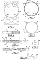
- FIG. 1 A perspective view of a preferred embodiment of the cylinder head gasket invention is depicted in Figure 1 .
- An elevational view of that embodiment is shown in Figure 2 .
- Figures 3, 4 and 5 are separate elevational views of the main components of the cylinder head gasket, namely the carrier member 27, the functional annular sealing ring 24, and one of the annular protection layer members 26, respectively.
- Figures 6-10 are cross-sectional views taken along lines A-A, B-B, C-C, D-D, and E-E, respectively, in Figure 2 .
- the carrier member 22 is a single plate layer of a cold rolled steel material.
- the carrier member has a plurality of openings formed in it, such as cylinder openings 30 for the piston member, coolant openings 32, 34, 36, 38 and 40 for coolant to pass through during passage through the engine, openings 42 and 44 to allow movement of the engine push rods, and opening 46 for passage of high pressure oil.
- the shape, structure and number and function of openings of the gasket member 20 shown in the drawings is exemplary.
- the gasket can have a wide variety of sizes, shapes and openings to fit different engines.
- the cylinder head gasket is mounted between the engine block and engine manifold in an engine and its purpose is to seal the joint between these two structures and prevent leakage of the combustion gases and materials, such as the engine coolant and the engine oils, between them.
- Most cylinder head gaskets include openings, for example, for engine coolant, push rods and engine oil, although the openings could have different functions, locations and sizes than the openings in the embodiment shown in the drawings.
- a cylinder head gasket could have a sufficient size and extended configuration to seal around two, three or more cylinders at the same time.
- the carrier member would have a series of structures like the one shown in Figure 2 positioned side by side and integrally formed as a one piece stamping.
- the sealing ring 24 has a circular annular shape and when mated with the carrier member, is positioned in the central cylinder opening 30.
- the sealing ring has a plurality of layers.
- the ring 24 has three layers which are called "functional" layers 50.
- the three functional layers are preferably made of a stainless steel material.
- the annular sealing ring can have a different number of layers, such as, for example, one, two, four, five, etc.
- the number of layers included depends on a number of factors, such as, for example, the size and type of engine and the pressures and heat caused by the fuel combustion in the cylinder.
- the protection layers 26 are made of a stainless steel material and are positioned on both sides of the sealing ring.
- FIG. 6 A cross-sectional view of the sealing ring member 24 and protection layer 26 are shown in Figure 6 . This cross-section is taken along line A-A in Figure 2 . As depicted, the annular body of the layers of the sealing ring 24 is positioned inside the cylinder opening 30 and in planar alignment with the plane of the carrier member.
- the sealing ring layers also have a plurality of tab members 60 positioned around their periphery.
- the tab members have openings 62 therein and when the sealing ring is positioned in the opening 30 in the carrier member 22, the tab members mate with recesses 64 in the carrier member. See Figure 3 .
- a protection ring layer 26 is positioned on each side of the sealing ring member 24 to form the gasket structure 20 as shown in Figure 2 .
- Each of the protection ring members 26 has a plurality of tab members 70 on the periphery thereon, as shown in Figure 5 . These tab members are also located and positioned in recesses 64 in the carrier member 27 when the gasket is assembled.
- Figures 7 and 8 are cross-sectional views taken along lines B-B and C-C, respectively, in Figure 2 .
- Figure 7 depicts the positioning of the tab members 60 and 70 in the recesses 64.
- the planes of the recesses 64 are physically recessed from the plane of the rest of the carrier member 22. This allows the tab members 70 of the protection layers 26 to overlap and extend radially outward past the ends of the tab members 60 of the sealing ring.
- tab members 60 and four tab members 70 there are five tab members 60 and four tab members 70 provided.
- the number and placement of these tab members on the components is exemplary and a different number and placement of the tab members can be provided. In the same manner, a different number and different placement of the corresponding recesses in the carrier member could also be provided. Moreover, the number and placement of the spot welds will depend on the number and location of the tabs and recesses.
- the openings 32, 34, 36, 38, 40, 42, 44 and 46 all preferably have elastomeric sealing materials positioned on them in order to seal the openings between the engine block and manifold and to prevent leakage.
- Figures 9 and 10 are cross-sections taken along lines D-D and E-E, respectively, in Figure 2 .
- the sealing members 120 are preferably molded on the carrier member 22 around each of the openings.
- the sealing members 120 form beads of sealing material that are positioned on the inside edges of the openings and extend radially inwardly into the opening as well as project transversely outwardly on both sides of the carrier member 22.
- the sealing members 120 shown in Figures 9 and 10 are representative of the sealing members positioned around all of the openings 32, 34, 36, 38, 40, 42, 44, and 46.
- the sealing members 120 provide tight and secure seals around the openings when the engine block and manifold are assembled together.
Landscapes
- Engineering & Computer Science (AREA)
- General Engineering & Computer Science (AREA)
- Mechanical Engineering (AREA)
- Chemical & Material Sciences (AREA)
- Combustion & Propulsion (AREA)
- Gasket Seals (AREA)
Claims (8)
- Zylinderkopfdichtung (20), umfassend:
ein einschichtiges Trägerelement (22), wobei das Trägerelement eine Zylinderöffnung (30) und eine Mehrzahl von anderen Öffnungen (32, 34, 36, 38, 40, 42, 44) aufweist, wobei ein ringförmiger Dichtungsring in der Zylinderöffnung (30) positioniert ist, wobei der Dichtungsring eine Mehrzahl von ringförmigen funktionalen Schichten (24) und ein Paar ringförmiger Schutzschichten (26) umfasst, wobei eine der Schutzschichten (26) auf jeder Seite des Dichtungsrings positioniert ist, gekennzeichnet durch:eine Mehrzahl von Ausnehmungen (64) im Trägerelement (22), wobei die Ausnehmungen (64) um den Umfang der Zylinderöffnung (30) in beabstandetem Verhältnis zueinander positioniert sind und zurückstehende Oberflächen bereitstellen, die sich in die planen Seiten des Trägerelements (22) erstrecken;eine Mehrzahl von ersten Laschenelementen (60), die sich radial nach außen von einem äußeren Umfang der funktionalen Schichten (24) erstrecken;eine Mehrzahl von zweiten Laschenelementen (70), die sich radial nach außen von einem äußeren Umfang von jeder der Schutzschichten (26) erstrecken;wobei sich die ersten Laschenelemente (60) mit den Ausnehmungen (64) zusammenfügen und sich die zweiten Laschenelemente (70) radial nach außen über die ersten Laschenelemente (60) hinaus erstrecken und in überlappendem Verhältnis in Hinblick auf die zurückstehenden Oberflächen positioniert sind. - Zylinderkopfdichtung (20) nach Anspruch 1, wobei die ersten und die zweiten Laschenelemente (60, 70) fest mit den Ausnehmungselementen (64) verbunden sind.
- Zylinderkopfdichtung (20) nach Anspruch 2, wobei die zweiten Laschenelemente (70) aneinander punktgeschweißt sind, um den Dichtungsring und die Schutzschichten (26) an dem Trägerelement (22) zu befestigen.
- Zylinderkopfdichtung (20) nach Anspruch 3, wobei die ersten Laschenelemente Öffnungen (62) darin aufweisen und die zweiten Laschenelemente (70) durch die Öffnungen (62) aneinander punktgeschweißt sind.
- Zylinderkopfdichtung (20) nach Anspruch 1, wobei drei funktionale Schichten (24) bereitgestellt sind.
- Zylinderkopfdichtung (20) nach Anspruch 1, die ferner eine Mehrzahl von zusätzlichen Öffnungen (32, 34, 36, 38, 40, 42, 44) im Trägerelement (22) und elastomere Dichtungselemente (120) umfasst, die um jede der zusätzlichen Öffnungen positioniert sind.
- Zylinderkopfdichtung (20) nach Anspruch 6, wobei sich die Dichtungselemente (120) radial nach innen in die Öffnungen (32, 34, 36, 38, 40, 42, 44) erstrecken und schräg nach außen auf beiden Seiten des Trägerelements (22) vorspringen.
- Zylinderkopfdichtung (20) nach Anspruch 1, wobei die ringförmigen Schutzschichten (26) im Wesentlichen dieselbe Größe und Form wie der ringförmige Dichtungsring aufweisen.
Applications Claiming Priority (2)
| Application Number | Priority Date | Filing Date | Title |
|---|---|---|---|
| US13/828,024 US8960682B2 (en) | 2013-03-14 | 2013-03-14 | Hybrid ring welded cylinder head gasket |
| PCT/US2014/019715 WO2014158735A1 (en) | 2013-03-14 | 2014-03-01 | Hybrid ring welded cylinder head gasket |
Publications (2)
| Publication Number | Publication Date |
|---|---|
| EP2971876A1 EP2971876A1 (de) | 2016-01-20 |
| EP2971876B1 true EP2971876B1 (de) | 2019-07-31 |
Family
ID=50336539
Family Applications (1)
| Application Number | Title | Priority Date | Filing Date |
|---|---|---|---|
| EP14711381.5A Active EP2971876B1 (de) | 2013-03-14 | 2014-03-01 | In einen hybridring geschweisste zylinderkopfdichtung |
Country Status (6)
| Country | Link |
|---|---|
| US (1) | US8960682B2 (de) |
| EP (1) | EP2971876B1 (de) |
| JP (1) | JP6450910B2 (de) |
| KR (1) | KR20150130518A (de) |
| CN (1) | CN105190130B (de) |
| WO (1) | WO2014158735A1 (de) |
Families Citing this family (3)
| Publication number | Priority date | Publication date | Assignee | Title |
|---|---|---|---|---|
| JP5723846B2 (ja) * | 2012-10-04 | 2015-05-27 | 内山工業株式会社 | ガスケット |
| USD747445S1 (en) * | 2014-02-10 | 2016-01-12 | Evoqua Water Technologies Llc | One piece gasket assembly |
| DE202019104931U1 (de) * | 2019-09-06 | 2020-12-08 | Reinz-Dichtungs-Gmbh | Zylinderkopfdichtung mit einer Trägerlage und zumindest einem Einsatzdichtelement |
Citations (2)
| Publication number | Priority date | Publication date | Assignee | Title |
|---|---|---|---|---|
| DE8102660U1 (de) * | 1981-07-09 | Elring Dichtungswerke Gmbh, 7012 Fellbach | Flachdichtung, insbesondere Zylinderkopfdichtung für Verbrennungskraftmaschinen | |
| DE3903918A1 (de) * | 1989-02-10 | 1990-08-16 | Goetze Ag | Flachdichtung, insbesondere zylinderkopfdichtung fuer verbrennungskraftmaschinen |
Family Cites Families (26)
| Publication number | Priority date | Publication date | Assignee | Title |
|---|---|---|---|---|
| US1782870A (en) | 1928-09-10 | 1930-11-25 | James G Dickson | Gasket |
| US2034610A (en) | 1934-01-22 | 1936-03-17 | Dickson Gasket Company | Gasket |
| DE1248397B (de) | 1966-06-15 | 1967-08-24 | Goetzewerke | Flanschdichtung |
| FR1592635A (de) | 1967-11-21 | 1970-05-19 | ||
| GB1305366A (de) | 1971-05-28 | 1973-01-31 | ||
| JPS51144646U (de) * | 1975-05-16 | 1976-11-20 | ||
| FR2446970A1 (fr) * | 1979-01-18 | 1980-08-14 | Renault Vehicules Ind | Joint de culasse perfectionne pour les moteurs a combustion interne |
| JPS5851041U (ja) * | 1981-10-01 | 1983-04-06 | 鎌苅 良太 | 金属ガスケツト |
| US4518168A (en) | 1984-03-02 | 1985-05-21 | Dana Corporation | Multi-thickness fire ring assembly |
| IT1186800B (it) | 1985-06-03 | 1987-12-16 | Tako Spa | Guarnizione per testa cilindri di motore a combustione interna esente da amianto |
| US4645217A (en) * | 1985-11-29 | 1987-02-24 | United Technologies Corporation | Finger seal assembly |
| US5338046A (en) * | 1992-12-18 | 1994-08-16 | Dana Corporation | Composite powdered metal retaining ring |
| US5505466A (en) | 1992-12-18 | 1996-04-09 | Dana Corporation | Cylinder head gasket with retaining ring and spring seal |
| US5890719A (en) | 1996-08-27 | 1999-04-06 | Parker-Hannifin Corporation | Combination metal and elastomer cylinder head gasket |
| DE19654283A1 (de) * | 1996-12-24 | 1998-06-25 | Reinz Dichtungs Gmbh | Metallische Flachdichtung |
| US5921558A (en) | 1997-04-15 | 1999-07-13 | Dana Corporation | High recovery combustion seal gasket |
| US6241253B1 (en) | 1998-06-08 | 2001-06-05 | Interface Solutions, Inc. | Edge coated soft gasket |
| US6093467A (en) | 1997-08-29 | 2000-07-25 | Interface Solutions, Inc. | High sealing gaskets |
| JP3792934B2 (ja) * | 1999-05-12 | 2006-07-05 | 内山工業株式会社 | ガスケットとその製造方法 |
| FR2827638B1 (fr) * | 2001-07-23 | 2003-09-19 | Meillor Sa | Joint de culasse comprenant un stoppeur bord a bord |
| WO2005012769A2 (en) * | 2003-07-28 | 2005-02-10 | Coltec Industries, Inc. | Head gasket assembly |
| CA2477342A1 (en) * | 2003-08-28 | 2005-02-28 | Freudenberg-Nok General Partnership | Improved sealing gasket with flexible stopper |
| US7726662B2 (en) * | 2006-07-10 | 2010-06-01 | Dana Automotive Systems Group, Llc | Stopped-active type cylinder head gasket |
| CN101910688A (zh) | 2008-06-21 | 2010-12-08 | 菲特尔莫古密封系统有限公司 | 平面密封件 |
| CN102483161B (zh) | 2009-08-19 | 2014-11-05 | 费德罗-莫格尔公司 | 汽缸盖垫片组件 |
| JP5425954B2 (ja) | 2012-03-14 | 2014-02-26 | 石川ガスケット株式会社 | ガスケット用ラバーリング |
-
2013
- 2013-03-14 US US13/828,024 patent/US8960682B2/en not_active Expired - Fee Related
-
2014
- 2014-03-01 WO PCT/US2014/019715 patent/WO2014158735A1/en active Application Filing
- 2014-03-01 CN CN201480025251.3A patent/CN105190130B/zh not_active Expired - Fee Related
- 2014-03-01 JP JP2016500529A patent/JP6450910B2/ja not_active Expired - Fee Related
- 2014-03-01 KR KR1020157029228A patent/KR20150130518A/ko not_active Application Discontinuation
- 2014-03-01 EP EP14711381.5A patent/EP2971876B1/de active Active
Patent Citations (2)
| Publication number | Priority date | Publication date | Assignee | Title |
|---|---|---|---|---|
| DE8102660U1 (de) * | 1981-07-09 | Elring Dichtungswerke Gmbh, 7012 Fellbach | Flachdichtung, insbesondere Zylinderkopfdichtung für Verbrennungskraftmaschinen | |
| DE3903918A1 (de) * | 1989-02-10 | 1990-08-16 | Goetze Ag | Flachdichtung, insbesondere zylinderkopfdichtung fuer verbrennungskraftmaschinen |
Also Published As
| Publication number | Publication date |
|---|---|
| JP6450910B2 (ja) | 2019-01-16 |
| JP2016512310A (ja) | 2016-04-25 |
| CN105190130A (zh) | 2015-12-23 |
| US8960682B2 (en) | 2015-02-24 |
| US20140265153A1 (en) | 2014-09-18 |
| KR20150130518A (ko) | 2015-11-23 |
| CN105190130B (zh) | 2017-08-08 |
| WO2014158735A1 (en) | 2014-10-02 |
| EP2971876A1 (de) | 2016-01-20 |
Similar Documents
| Publication | Publication Date | Title |
|---|---|---|
| US6371489B1 (en) | Cylinder-head gasket for internal combustion engine | |
| EP2188554B1 (de) | Metallzylinderkopfdichtung | |
| EP2971874B1 (de) | Kleine elastische dichtung in einer abdichtungsprägung einer hauptbrennkammer | |
| EP2671005B1 (de) | Mehrschichtige statische dichtung mit sekundärem kompressionsbegrenzer | |
| EP2855983B1 (de) | Metalldichtung | |
| EP2971876B1 (de) | In einen hybridring geschweisste zylinderkopfdichtung | |
| EP2764282B1 (de) | Mehrschichtige dichtung mit einer segmentierten integrierten stopfenfunktion | |
| US10113505B2 (en) | Gasket and engine with the gasket | |
| EP2681470B1 (de) | Zylinderkopfdichtung | |
| CN108884938B (zh) | 内燃机用密封垫 | |
| KR20170021250A (ko) | 압축 제한기 및 풀 비드를 구비한 실린더 헤드 가스켓 | |
| KR100935388B1 (ko) | 낌방지 적층형 가스켓 | |
| GB2532971A (en) | Cylinder head gasket | |
| JP2009156395A (ja) | 金属製ガスケット | |
| CN210217958U (zh) | 发动机气路密封系统和发动机 | |
| WO2017120177A1 (en) | Multi-layer gasket assembly | |
| US10119494B2 (en) | Multi-layer gasket assembly |
Legal Events
| Date | Code | Title | Description |
|---|---|---|---|
| PUAI | Public reference made under article 153(3) epc to a published international application that has entered the european phase |
Free format text: ORIGINAL CODE: 0009012 |
|
| 17P | Request for examination filed |
Effective date: 20150914 |
|
| AK | Designated contracting states |
Kind code of ref document: A1 Designated state(s): AL AT BE BG CH CY CZ DE DK EE ES FI FR GB GR HR HU IE IS IT LI LT LU LV MC MK MT NL NO PL PT RO RS SE SI SK SM TR |
|
| AX | Request for extension of the european patent |
Extension state: BA ME |
|
| DAX | Request for extension of the european patent (deleted) | ||
| STAA | Information on the status of an ep patent application or granted ep patent |
Free format text: STATUS: EXAMINATION IS IN PROGRESS |
|
| 17Q | First examination report despatched |
Effective date: 20180712 |
|
| REG | Reference to a national code |
Ref country code: DE Ref legal event code: R079 Ref document number: 602014050806 Country of ref document: DE Free format text: PREVIOUS MAIN CLASS: F16J0015080000 Ipc: F16J0015060000 |
|
| GRAP | Despatch of communication of intention to grant a patent |
Free format text: ORIGINAL CODE: EPIDOSNIGR1 |
|
| STAA | Information on the status of an ep patent application or granted ep patent |
Free format text: STATUS: GRANT OF PATENT IS INTENDED |
|
| RIC1 | Information provided on ipc code assigned before grant |
Ipc: F16J 15/12 20060101ALI20190411BHEP Ipc: F16J 15/08 20060101ALI20190411BHEP Ipc: F16J 15/06 20060101AFI20190411BHEP Ipc: F02F 11/00 20060101ALI20190411BHEP |
|
| INTG | Intention to grant announced |
Effective date: 20190515 |
|
| GRAS | Grant fee paid |
Free format text: ORIGINAL CODE: EPIDOSNIGR3 |
|
| GRAA | (expected) grant |
Free format text: ORIGINAL CODE: 0009210 |
|
| STAA | Information on the status of an ep patent application or granted ep patent |
Free format text: STATUS: THE PATENT HAS BEEN GRANTED |
|
| RAP1 | Party data changed (applicant data changed or rights of an application transferred) |
Owner name: TENNECO INC. |
|
| AK | Designated contracting states |
Kind code of ref document: B1 Designated state(s): AL AT BE BG CH CY CZ DE DK EE ES FI FR GB GR HR HU IE IS IT LI LT LU LV MC MK MT NL NO PL PT RO RS SE SI SK SM TR |
|
| REG | Reference to a national code |
Ref country code: CH Ref legal event code: EP Ref country code: GB Ref legal event code: FG4D |
|
| REG | Reference to a national code |
Ref country code: AT Ref legal event code: REF Ref document number: 1161240 Country of ref document: AT Kind code of ref document: T Effective date: 20190815 |
|
| REG | Reference to a national code |
Ref country code: IE Ref legal event code: FG4D |
|
| REG | Reference to a national code |
Ref country code: DE Ref legal event code: R096 Ref document number: 602014050806 Country of ref document: DE |
|
| REG | Reference to a national code |
Ref country code: NL Ref legal event code: MP Effective date: 20190731 |
|
| REG | Reference to a national code |
Ref country code: LT Ref legal event code: MG4D |
|
| REG | Reference to a national code |
Ref country code: AT Ref legal event code: MK05 Ref document number: 1161240 Country of ref document: AT Kind code of ref document: T Effective date: 20190731 |
|
| PG25 | Lapsed in a contracting state [announced via postgrant information from national office to epo] |
Ref country code: PT Free format text: LAPSE BECAUSE OF FAILURE TO SUBMIT A TRANSLATION OF THE DESCRIPTION OR TO PAY THE FEE WITHIN THE PRESCRIBED TIME-LIMIT Effective date: 20191202 Ref country code: FI Free format text: LAPSE BECAUSE OF FAILURE TO SUBMIT A TRANSLATION OF THE DESCRIPTION OR TO PAY THE FEE WITHIN THE PRESCRIBED TIME-LIMIT Effective date: 20190731 Ref country code: SE Free format text: LAPSE BECAUSE OF FAILURE TO SUBMIT A TRANSLATION OF THE DESCRIPTION OR TO PAY THE FEE WITHIN THE PRESCRIBED TIME-LIMIT Effective date: 20190731 Ref country code: HR Free format text: LAPSE BECAUSE OF FAILURE TO SUBMIT A TRANSLATION OF THE DESCRIPTION OR TO PAY THE FEE WITHIN THE PRESCRIBED TIME-LIMIT Effective date: 20190731 Ref country code: AT Free format text: LAPSE BECAUSE OF FAILURE TO SUBMIT A TRANSLATION OF THE DESCRIPTION OR TO PAY THE FEE WITHIN THE PRESCRIBED TIME-LIMIT Effective date: 20190731 Ref country code: LT Free format text: LAPSE BECAUSE OF FAILURE TO SUBMIT A TRANSLATION OF THE DESCRIPTION OR TO PAY THE FEE WITHIN THE PRESCRIBED TIME-LIMIT Effective date: 20190731 Ref country code: NO Free format text: LAPSE BECAUSE OF FAILURE TO SUBMIT A TRANSLATION OF THE DESCRIPTION OR TO PAY THE FEE WITHIN THE PRESCRIBED TIME-LIMIT Effective date: 20191031 Ref country code: NL Free format text: LAPSE BECAUSE OF FAILURE TO SUBMIT A TRANSLATION OF THE DESCRIPTION OR TO PAY THE FEE WITHIN THE PRESCRIBED TIME-LIMIT Effective date: 20190731 Ref country code: BG Free format text: LAPSE BECAUSE OF FAILURE TO SUBMIT A TRANSLATION OF THE DESCRIPTION OR TO PAY THE FEE WITHIN THE PRESCRIBED TIME-LIMIT Effective date: 20191031 |
|
| PG25 | Lapsed in a contracting state [announced via postgrant information from national office to epo] |
Ref country code: IS Free format text: LAPSE BECAUSE OF FAILURE TO SUBMIT A TRANSLATION OF THE DESCRIPTION OR TO PAY THE FEE WITHIN THE PRESCRIBED TIME-LIMIT Effective date: 20191130 Ref country code: AL Free format text: LAPSE BECAUSE OF FAILURE TO SUBMIT A TRANSLATION OF THE DESCRIPTION OR TO PAY THE FEE WITHIN THE PRESCRIBED TIME-LIMIT Effective date: 20190731 Ref country code: GR Free format text: LAPSE BECAUSE OF FAILURE TO SUBMIT A TRANSLATION OF THE DESCRIPTION OR TO PAY THE FEE WITHIN THE PRESCRIBED TIME-LIMIT Effective date: 20191101 Ref country code: RS Free format text: LAPSE BECAUSE OF FAILURE TO SUBMIT A TRANSLATION OF THE DESCRIPTION OR TO PAY THE FEE WITHIN THE PRESCRIBED TIME-LIMIT Effective date: 20190731 Ref country code: LV Free format text: LAPSE BECAUSE OF FAILURE TO SUBMIT A TRANSLATION OF THE DESCRIPTION OR TO PAY THE FEE WITHIN THE PRESCRIBED TIME-LIMIT Effective date: 20190731 Ref country code: ES Free format text: LAPSE BECAUSE OF FAILURE TO SUBMIT A TRANSLATION OF THE DESCRIPTION OR TO PAY THE FEE WITHIN THE PRESCRIBED TIME-LIMIT Effective date: 20190731 |
|
| PG25 | Lapsed in a contracting state [announced via postgrant information from national office to epo] |
Ref country code: TR Free format text: LAPSE BECAUSE OF FAILURE TO SUBMIT A TRANSLATION OF THE DESCRIPTION OR TO PAY THE FEE WITHIN THE PRESCRIBED TIME-LIMIT Effective date: 20190731 |
|
| PG25 | Lapsed in a contracting state [announced via postgrant information from national office to epo] |
Ref country code: RO Free format text: LAPSE BECAUSE OF FAILURE TO SUBMIT A TRANSLATION OF THE DESCRIPTION OR TO PAY THE FEE WITHIN THE PRESCRIBED TIME-LIMIT Effective date: 20190731 Ref country code: PL Free format text: LAPSE BECAUSE OF FAILURE TO SUBMIT A TRANSLATION OF THE DESCRIPTION OR TO PAY THE FEE WITHIN THE PRESCRIBED TIME-LIMIT Effective date: 20190731 Ref country code: EE Free format text: LAPSE BECAUSE OF FAILURE TO SUBMIT A TRANSLATION OF THE DESCRIPTION OR TO PAY THE FEE WITHIN THE PRESCRIBED TIME-LIMIT Effective date: 20190731 Ref country code: DK Free format text: LAPSE BECAUSE OF FAILURE TO SUBMIT A TRANSLATION OF THE DESCRIPTION OR TO PAY THE FEE WITHIN THE PRESCRIBED TIME-LIMIT Effective date: 20190731 |
|
| PGFP | Annual fee paid to national office [announced via postgrant information from national office to epo] |
Ref country code: IT Payment date: 20200316 Year of fee payment: 7 Ref country code: DE Payment date: 20200214 Year of fee payment: 7 |
|
| PG25 | Lapsed in a contracting state [announced via postgrant information from national office to epo] |
Ref country code: CZ Free format text: LAPSE BECAUSE OF FAILURE TO SUBMIT A TRANSLATION OF THE DESCRIPTION OR TO PAY THE FEE WITHIN THE PRESCRIBED TIME-LIMIT Effective date: 20190731 Ref country code: SM Free format text: LAPSE BECAUSE OF FAILURE TO SUBMIT A TRANSLATION OF THE DESCRIPTION OR TO PAY THE FEE WITHIN THE PRESCRIBED TIME-LIMIT Effective date: 20190731 Ref country code: SK Free format text: LAPSE BECAUSE OF FAILURE TO SUBMIT A TRANSLATION OF THE DESCRIPTION OR TO PAY THE FEE WITHIN THE PRESCRIBED TIME-LIMIT Effective date: 20190731 Ref country code: IS Free format text: LAPSE BECAUSE OF FAILURE TO SUBMIT A TRANSLATION OF THE DESCRIPTION OR TO PAY THE FEE WITHIN THE PRESCRIBED TIME-LIMIT Effective date: 20200224 |
|
| REG | Reference to a national code |
Ref country code: DE Ref legal event code: R097 Ref document number: 602014050806 Country of ref document: DE |
|
| PGFP | Annual fee paid to national office [announced via postgrant information from national office to epo] |
Ref country code: FR Payment date: 20200219 Year of fee payment: 7 |
|
| PLBE | No opposition filed within time limit |
Free format text: ORIGINAL CODE: 0009261 |
|
| STAA | Information on the status of an ep patent application or granted ep patent |
Free format text: STATUS: NO OPPOSITION FILED WITHIN TIME LIMIT |
|
| PG2D | Information on lapse in contracting state deleted |
Ref country code: IS |
|
| PG25 | Lapsed in a contracting state [announced via postgrant information from national office to epo] |
Ref country code: IS Free format text: LAPSE BECAUSE OF FAILURE TO SUBMIT A TRANSLATION OF THE DESCRIPTION OR TO PAY THE FEE WITHIN THE PRESCRIBED TIME-LIMIT Effective date: 20191030 |
|
| 26N | No opposition filed |
Effective date: 20200603 |
|
| PG25 | Lapsed in a contracting state [announced via postgrant information from national office to epo] |
Ref country code: SI Free format text: LAPSE BECAUSE OF FAILURE TO SUBMIT A TRANSLATION OF THE DESCRIPTION OR TO PAY THE FEE WITHIN THE PRESCRIBED TIME-LIMIT Effective date: 20190731 |
|
| PG25 | Lapsed in a contracting state [announced via postgrant information from national office to epo] |
Ref country code: MC Free format text: LAPSE BECAUSE OF FAILURE TO SUBMIT A TRANSLATION OF THE DESCRIPTION OR TO PAY THE FEE WITHIN THE PRESCRIBED TIME-LIMIT Effective date: 20190731 |
|
| REG | Reference to a national code |
Ref country code: CH Ref legal event code: PL |
|
| REG | Reference to a national code |
Ref country code: BE Ref legal event code: MM Effective date: 20200331 |
|
| PG25 | Lapsed in a contracting state [announced via postgrant information from national office to epo] |
Ref country code: LU Free format text: LAPSE BECAUSE OF NON-PAYMENT OF DUE FEES Effective date: 20200301 |
|
| PG25 | Lapsed in a contracting state [announced via postgrant information from national office to epo] |
Ref country code: CH Free format text: LAPSE BECAUSE OF NON-PAYMENT OF DUE FEES Effective date: 20200331 Ref country code: IE Free format text: LAPSE BECAUSE OF NON-PAYMENT OF DUE FEES Effective date: 20200301 Ref country code: LI Free format text: LAPSE BECAUSE OF NON-PAYMENT OF DUE FEES Effective date: 20200331 |
|
| PG25 | Lapsed in a contracting state [announced via postgrant information from national office to epo] |
Ref country code: BE Free format text: LAPSE BECAUSE OF NON-PAYMENT OF DUE FEES Effective date: 20200331 |
|
| GBPC | Gb: european patent ceased through non-payment of renewal fee |
Effective date: 20200301 |
|
| PG25 | Lapsed in a contracting state [announced via postgrant information from national office to epo] |
Ref country code: GB Free format text: LAPSE BECAUSE OF NON-PAYMENT OF DUE FEES Effective date: 20200301 |
|
| REG | Reference to a national code |
Ref country code: DE Ref legal event code: R119 Ref document number: 602014050806 Country of ref document: DE |
|
| PG25 | Lapsed in a contracting state [announced via postgrant information from national office to epo] |
Ref country code: FR Free format text: LAPSE BECAUSE OF NON-PAYMENT OF DUE FEES Effective date: 20210331 Ref country code: DE Free format text: LAPSE BECAUSE OF NON-PAYMENT OF DUE FEES Effective date: 20211001 |
|
| PG25 | Lapsed in a contracting state [announced via postgrant information from national office to epo] |
Ref country code: IT Free format text: LAPSE BECAUSE OF NON-PAYMENT OF DUE FEES Effective date: 20210301 |
|
| PG25 | Lapsed in a contracting state [announced via postgrant information from national office to epo] |
Ref country code: MT Free format text: LAPSE BECAUSE OF FAILURE TO SUBMIT A TRANSLATION OF THE DESCRIPTION OR TO PAY THE FEE WITHIN THE PRESCRIBED TIME-LIMIT Effective date: 20190731 Ref country code: CY Free format text: LAPSE BECAUSE OF FAILURE TO SUBMIT A TRANSLATION OF THE DESCRIPTION OR TO PAY THE FEE WITHIN THE PRESCRIBED TIME-LIMIT Effective date: 20190731 |
|
| PG25 | Lapsed in a contracting state [announced via postgrant information from national office to epo] |
Ref country code: MK Free format text: LAPSE BECAUSE OF FAILURE TO SUBMIT A TRANSLATION OF THE DESCRIPTION OR TO PAY THE FEE WITHIN THE PRESCRIBED TIME-LIMIT Effective date: 20190731 |