EP2969870B1 - Verfahren zur abgabe von festen produkten - Google Patents
Verfahren zur abgabe von festen produkten Download PDFInfo
- Publication number
- EP2969870B1 EP2969870B1 EP14776122.5A EP14776122A EP2969870B1 EP 2969870 B1 EP2969870 B1 EP 2969870B1 EP 14776122 A EP14776122 A EP 14776122A EP 2969870 B1 EP2969870 B1 EP 2969870B1
- Authority
- EP
- European Patent Office
- Prior art keywords
- solid product
- fluid
- dispenser
- product
- solution
- Prior art date
- Legal status (The legal status is an assumption and is not a legal conclusion. Google has not performed a legal analysis and makes no representation as to the accuracy of the status listed.)
- Active
Links
Images




Classifications
-
- B—PERFORMING OPERATIONS; TRANSPORTING
- B01—PHYSICAL OR CHEMICAL PROCESSES OR APPARATUS IN GENERAL
- B01F—MIXING, e.g. DISSOLVING, EMULSIFYING OR DISPERSING
- B01F21/00—Dissolving
- B01F21/20—Dissolving using flow mixing
- B01F21/22—Dissolving using flow mixing using additional holders in conduits, containers or pools for keeping the solid material in place, e.g. supports or receptacles
- B01F21/221—Dissolving using flow mixing using additional holders in conduits, containers or pools for keeping the solid material in place, e.g. supports or receptacles comprising constructions for blocking or redispersing undissolved solids
Definitions
- Solutions formed from dissolving a solid product in a fluid have been long known and utilized for many applications. Accordingly, solution-forming devices have been developed in order to create desired solutions without the need to manually create them. Instead, a fluid is supplied to the device, the solution is formed therein and then flows out the device. Such devices may be used to create cleaning and sanitizing solutions or other desired solutions.
- US5262132A1 and US4957134A1 disclose a freestanding product dispenser and method for dispensing a solution of a solid product.
- US6287466B1 discloses a freestanding product dispenser with pegs to support the solid product to increase the exposed area of a solid product to a liquid.
- the present invention relates to methods and apparatuses for dispensing a solid product in a solution.
- Apparatuses are generally freestanding comprise an inlet portion in which fluid is directed. From the inlet portion, the fluid flows to a reaction portion, where it encounters the solid product. In the reaction portion, the fluid dissolves the product and forms a solution. The solution then exits the apparatus through an outlet portion.
- the product in the reaction portion may be housed in a product guide, which may be shaped to receive a particular product.
- the product may be covered by a lid to protect it from encountering undesired fluid.
- the apparatus may additionally comprise a gate, generally disposed between the inlet portion and the product so that it may also prevent fluid from undesirable contacting the product.
- the gate may be raised and lowered to control the amount of fluid that passes thereunder and reacts with the product.
- An essential feature of the invention are pegs on which the product sets.
- the fluid then, may flow through the pegs and underneath the product, dissolving it from underneath.
- the invention may also comprise a hull shaped to promote even fluid flow and dissolution of the product as the fluid travels through the reaction portion.
- Other embodiments comprise a wall and an annular channel such that fluid flowing into the apparatus contacts the wall and fills the annular channel, which may at least partially surround the product. Once the fluid level reaches the height of the wall, it spills over into the reaction portion. Thus, if the channel does at least partially surround the product, fluid spilling over therefrom may be incident on the product from multiple directions.
- the present invention is aimed at creating an easy-to-use, cost-effective, and repeatable means for creating solutions of appropriate concentrations.
- Embodiments of the invention are designed to dispense a solution formed from a solid product and an incident fluid such as water.
- the solid product may comprise many different products, including but not limited to a sanitizer, a detergent, or a floor care product, as many applications of the present invention may involve creating a solution for a cleaning process. In many cases, it is desirable to achieve and maintain a certain concentration of a solution for cost, performance, or even regulatory reasons.
- FIG. 1a shows a perspective view of an embodiment of the invention.
- This embodiment of a solid product dispenser 100 comprises an inlet portion 102, which receives an incident fluid, a reaction portion 104, in which the fluid encounters the solid product, and an outlet portion 106, from which the solution of the two is dispensed.
- the reaction portion comprises a solid product 112 intended for dissolving in a fluid to create a solution. Fluid is introduced into this embodiment by being supplied to the inlet portion 102. From there, it flows into the reaction portion, where it comes into contact with the solid product. Fluid dissolves contacting portions of the solid product 112, which then dissolves into the fluid, thereby creating a solution. This solution continues through the reaction portion to the outlet portion, where it is dispensed from the invention.
- the embodiment of the invention shown in FIG. 1a further comprises a product guide 110, which is housed at least partially within the reaction portion and is configured to hold the solid product.
- a product guide 110 which is housed at least partially within the reaction portion and is configured to hold the solid product.
- Particular embodiments of the invention may be designed to hold a particular product, which may be shaped in a particular defining way.
- the product guide of various embodiments may be uniquely shaped so as to receive a particular solid product.
- the shape of the solid product is indicative of the solid product itself.
- a pentagonal product may comprise a detergent
- a hexagonal product may comprise a sanitizer
- a square product may comprise a floor care product.
- different embodiments of the invention may be used for different desired applications, as the shape of the product guide may indicate the desired product of use.
- Additional embodiments of the invention may comprise a product lockout, which may prevent a product of an incorrect shape, and therefore incorrect composition, from being used.
- Embodiments of the present invention may comprise various materials, for example metals, plastics, composite, etc. Further embodiments may comprise polypropylene.
- FIG. 1b shows a top-down view of an embodiment of the invention similar to the one illustrated in FIG. 1a . Shown is the inlet portion 102, the reaction portion 104, and the outlet portion 106, as well as the product guide 110 and solid product 112.
- FIG. 1c shows a cross-sectional view of the embodiment of FIG. 1b , taken at line 1-1 in FIG. 1b . As shown, this embodiment further comprises a lead-in ramp 114 as part of the inlet portion 102, such that fluid incident to the inlet portion 102 impinges on the lead-in ramp 114. Fluid then flows down the lead-in ramp 114 into the reaction portion 104.
- the lead-in ramp 114 may provide a surface oriented at an angle to the fluid incident to the inlet portion 102. In this case, the angular relationship may minimize undesired splashing of the fluid either out of the dispenser or onto the solid product 112. Additionally, the lead-in ramp may comprise a textured surface to encourage the incident fluid to spread out as it travels towards the reaction portion. Some embodiments may also comprise a gate 116 in order to at least prevent undesired splashing of incident fluid onto the surface of the product 112. In some embodiments, the gate may additionally provide the boundary between the inlet portion and the reaction portion. In still further embodiments, the gate may additionally regulate the rate of flow of the fluid between the inlet portion and the reaction portion, and may be adjusted in height to change the rate of flow.
- the dispenser comprises pegs 122, shown in FIG. 1c as being located on the bottom surface of the dispenser, intended to support the solid product 112 above the floor of the reaction portion 104 as fluid flows through the spaces therebetween.
- the pegs 122 are shorter than the depth of the fluid so that the fluid will contact at least a portion of the solid product 112 as it flows through the pegs 122.
- Taller pegs 122 will support the product 112 further above the base of the dispenser than will shorter pegs 122, thereby supporting the product 112 further out of the fluid and changing the amount of surface contact therebetween.
- Peg heights may be optimized in a laboratory or factory prior to implementation into the dispenser so that a desired amount of interaction between the solid product 112 and the fluid may occur depending on a either a specific incident fluid flow rate or a particular range thereof. Adjustable or interchangeable pegs are also contemplated, allowing the end user to change the height of the pegs 122. Pegs 122 may also be affixed to a peg plate, which may itself be entirely replaceable by the user.
- the number or area density of pegs may vary from embodiment to embodiment; however it will be appreciated that a lower number of pegs will result in more mass of the solid product per surface area of pegs, potentially creating a risk for the solid product 112 to sink down onto the pegs 122 and embedding them therein. Too many pegs 122, however, may inhibit the ability for fluid to flow through the dispenser. After flowing through the pegs 122 and contacting the solid product 112, fluid may exit the dispenser through the outlet portion 106 via an opening to the outside of the dispenser.
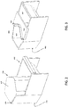
- FIGS. 2 and 3 show alternative embodiments of the invention.
- the dispenser of FIG. 2 further comprises a closable lid 224 which, when closed, covers the solid product within the reaction portion 204.
- the lid covers the top and the side of the solid product facing the inlet portion 202, shielding it from undesired exposure to the incident fluid such as splashing from the inlet portion 202 or incorrect operation of the dispenser.
- the lid 224 may be attached to the dispenser by attachment means, such as a hinge 226 or other method of attachment known in the art, or it may be entirely removable from the dispenser.
- FIG. 3 shows an embodiment of the invention with no lid, but further comprising a splash guard 318. Splash guard 318 acts in conjunction with gate 316 to prevent undesired fluid from coming into contact with the solid product by blocking fluid that may otherwise splash up and over the gate
- the concentration of the solid product in the solution formed is dependent upon several factors. Fluid temperature and flow rate, as well as the amount of solid product contacting the fluid and any specific chemistry therebetween, may affect the concentration of the solution. Desired concentrations may vary from application to application, however it is advantageous to be able to both achieve and maintain a desired concentration. Thus, in some embodiments, it is preferred that the solid product be dissolved uniformly across the bottom surface by the fluid. This may be advantageous since otherwise, non-uniform dissolution may cause surface deformations on the solid product, resulting in a change of surface area exposed to the incident fluid. This may then result in undesired changes in the concentration of the solid product in the solution.
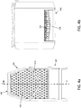
- FIGS. 4a and 4b show embodiments of the invention comprising components aimed to create and/or maintain uniform dissolution of the solid product substantially across a single surface.
- FIG. 4a shows a top view of an embodiment of the invention. As was the case with the embodiment illustrated in FIG. 1c , the embodiment of FIG. 4a comprises pegs 422 on the bottom surface of the dispenser, however these pegs 422 can be seen to extend beyond the perimeter of the gate 416, which encloses the solid product, towards the inlet portion, providing pegs in the dispenser not supporting the solid product, but rather "upstream" from the product.
- the pegs 422 extend outside of the area where the solid product is to be held so that this initial contact with the pegs, and its induced turbulence and potential upward displacement of fluid, may occur prior to the fluid reaching the product, by which time the fluid may reach a steady state flow pattern.
- three rows of pegs 422 are located between the inlet portion and the nearest point of the gate.
- FIG. 4b shows an elevational view of an embodiment of the invention intended to help fix such non-uniformity. Shown is the outlet portion 406 of the dispenser from where the solution is dispensed. Through the outlet portion 406, the pegs 422 are visible, as is the base of the reaction portion of the dispenser, referred here to as the hull 428; however the hull need not be limited to the base of the reaction portion.
- the hull 428 comprises a V-shaped hull 428a, as its cross-section resembles that of the letter "V".
- the V-shaped hull 428a acts to draw more fluid from the edges of the dispenser towards the middle while fluid is flowing through the reaction portion. This reduces the enhanced erosion nearer the edges described previously, resulting in a more uniform dissolution process across the bottom surface of the solid product and a greater likelihood of maintaining a desired concentration during operation.
- the 'V' shape of the hull shown herein is not the only shape that may be used to accomplish such a process.
- Other hull shapes are contemplated such as a "U" shape, a parabolic shape, or any other shape that may divert some of the fluid flow away from the edges and towards the central pathway from the inlet to the outlet.
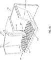
- FIG. 4c is a cross-sectional perspective view an embodiment of the invention comprising features illustrated in FIGS. 4a and 4b , with the cross section taken at line 4-4 in FIG. 4a .
- the fluid enters the inlet portion 402 which comprises a lead-in ramp 414.
- the fluid contacts and flows down the lead-in ramp 414, which directs the fluid towards pegs 422 along the bottom of the dispenser.
- the fluid contacts a first series of pegs 422, which may induce turbulence into the fluid. It is assumed, however, that after the fluid has passed the first series of pegs 422, much of the induced turbulence will have substantially subsided, resulting in generally steady state fluid flow beyond this point.
- this first series of pegs comprises at least three rows of pegs in order to provide a sufficiently long flow path for the fluid flow to reach a steady state.
- fluid ideally flows in a steady-state through a gap 420 under the gate 416 and into the area surrounded by the product guide, configured for holding the solid product atop the pegs 422 therein.
- the product guide 410 With a solid product in place in the product guide 410, fluid contacts the solid product and erodes it, forming a solution of the product in the fluid. The solution then flows to the outlet portion 406, where it exits the dispenser.
- Embodiments such as the one shown in FIG.
- FIG. 4c may additionally comprise a hull such as the aforementioned V-shaped hull 428a to aid in uniform dissolution of the solid product. While the reaction portion of FIG. 4c is designed to hold a product of a particular shape, it will be appreciated that embodiments similar to the one shown in FIG. 4c may be configured for receiving products of differing shapes.
- fluid may enter the dispenser via an inlet portion and flow into the reaction portion in a first direction and flow out of the outlet portion in a second direction, different from the first. It will be appreciated by those skilled in the art that many configurations fall within the scope of the invention. Another such alternate configuration is described below.
- FIGS. 5a , 5b , and 5c illustrate yet another embodiment of the invention, comprising inlet 502, reaction 504, and outlet 506, portions.
- FIG. 5a is a perspective view of an embodiment of the invention, showing the inlet 502, reaction 504, and outlet 506 portions.
- FIG. 5b is a top-down view of the embodiment of the invention of FIG. 5a
- FIG. 5c is a cross-sectional view of the embodiment, taken at 5-5 in FIG. 5b .
- fluid is received via inlet portion 502, where it contacts lead-in ramp 514. Fluid flows down the ramp 514 and into an annular channel 532 formed by a wall 534. With nowhere else to flow, the fluid accumulates in the annular channel 532, causing the fluid level to rise.
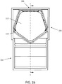
- the embodiment described above allows the fluid to impinge on each side of the solid product, as the fluid will fill the annular channel uniformly and spill over and flow towards the product on all sides, provided the wall height is uniform. This is in contrast to the substantially single-dimensional flow patterns of the previous embodiments, and may contribute to a more even pattern of dissolution across the solid product. While the embodiment of FIG. 5c suggests a circular (annular) channel, other shapes may also be used. As described above, various solid products may be shaped in various defining ways, and thus, it may be that to receive a particular desired product, the channel and/or wall forming the channel may be shaped similarly to the desired product, or arranged in any other shape.
- an embodiment of the invention may be used in conjunction with a three-compartment sink; wherein different solutions are desired in each compartment for a multistep procedure, for example washing dishes.
- a first embodiment of the invention may be configured to dispense a solution comprising a first solid product into a first compartment of the sink
- a second embodiment of the invention may be configured to dispense a solution comprising a second solid product into a second compartment of the sink.
- a fluid such as water conveniently supplied by the sink, to each of the embodiments of the invention, thereby dispensing the desired first and second solutions in separate compartments of the sink.
- embodiments of the invention could be used to produce a detergent solution in the first compartment of the sink and a sanitizer solution in the third compartment while leaving only water in the second compartment, organizing the sink contents in order of use.
- Additional embodiments of the invention comprising additional solid products may be used in processes requiring additional solutions.
- Embodiments of the invention may also comprise a mounting member for attaching the dispenser to or near a container for receiving the dispensed solution.
- the dispenser may be attachable to the edge of a sink via the mounting member so that as a solution flows out of the outlet portion, it flows directly into the sink. It may additionally be attached such that the faucet of the sink conveniently directs fluid into the inlet portion of the invention.
- the dispenser may also be mounted on an alternative container such as a mop bucket, for example. In this exemplary configuration, the dispenser may be mounted on the mop bucket and arranged so that a created solution such as a floor cleaning solution flows directly into the bucket.
- Other embodiments of the invention may enable the mounting of the dispenser to a wall in a location that may be proximate a fluid source.
- the fluid source may supply fluid to the inlet portion of the dispenser, and the solution may flow out of the outlet portion into any number of desired locations, such as a sink compartment or a bucket.
- embodiments of the invention configured for holding various solid products may have similar or like mounting members, allowing for these embodiments to be interchangeably mounted on a container, wall, or other mounting location appreciated by those skilled in the art.
- elements of the invention may be adjusted in a factory or laboratory setting in order to achieve a concentration within the desired range for a particular operating condition.
- elements may be optimized in order to achieve a concentration within a desired range for any in a range of typical operating conditions, for example a temperature range of 32,2-60 degrees Celsius (90-140 degrees Fahrenheit) with a flow rate in the range of 1,89 to 3,79 liters-per-minute (four to eight gallons-per-minute).
- elements that may be optimized include peg size, shape, and number density, along with the shape and depth of the hull.
- the product guide may be shaped such that it receives a particularly shaped solid product. Often, this solid product is of the same shape as the product guide, as shown in the pentagonal configuration of FIG. 1a , and further prohibits differently shaped products, such as a hexagonal product, from entering the product guide.
- Different embodiments of the invention may further be configured to hold stacks of multiple solid product blocks, wherein two pentagonal shaped product blocks may be stacked on one another in the product guide, for example. Maintaining a stack of at least two product blocks in the product guide may be advantageous, since if the first dissolves completely, there remains product available to dissolve and form the solution. Otherwise fluid may enter the dispenser, encounter no product block, and continue out of dispenser substantially unchanged.
Landscapes
- Chemical & Material Sciences (AREA)
- Chemical Kinetics & Catalysis (AREA)
- Feeding, Discharge, Calcimining, Fusing, And Gas-Generation Devices (AREA)
- Containers And Packaging Bodies Having A Special Means To Remove Contents (AREA)
Claims (12)
- Verfahren zum Abgeben einer Lösung eines festen Produktes (112), wobei das Verfahren Folgendes umfasst:
Bereitstellen eines eigenständigen Spenders (100) für ein frei fließendes Produkt, wobei der Spender (100) Folgendes umfasst:einen Einlassabschnitt (102) zum Aufnehmen von Fluid, wobei der Einlassabschnitt (102) ferner einen Reaktionsabschnitt (104) umfasst, in dem die Lösung gebildet wird, wobei der Reaktionsabschnitt (104) ferner konfiguriert ist, um ein besonders geformtes festes Produkt (112) aufzunehmen, und einen Auslassabschnitt (106) zum Abgeben der Lösung; undLeiten von Fluid zu dem Einlassabschnitt (102), wodurchdas Fluid mit dem festen Produkt (112) in Kontakt kommt, das in dem Reaktionsabschnitt (104) enthalten ist, und das Produkt auflöst, wodurch eine Lösung der Flüssigkeit und des Produktes erzeugt wird; unddie Lösung aus dem Auslassabschnitt (106) abgegeben wird, dadurch gekennzeichnet, dass der Spender ferner Stifte (122) umfasst, die das feste Produkt (112) tragen, undwobei das Fluid durch die Räume zwischen den Stiften (122) fließt, wobei der Spender (100) ferner Stifte (122) umfasst, die in dem Einlassabschnitt (102) derart angeordnet sind, dass die Flüssigkeit mit einer Reihe von Stiften (122) in Kontakt kommt und diese durchströmt, bevor sie auf das feste Produkt (112) trifft. - Verfahren nach Anspruch 1, wobei der Spender (100) einen Rumpf (428) im Wesentlichen unterhalb des festen Produktes (112) umfasst, um den Fluidstrom derart zu lenken, dass der Querschnitt des festen Produkts (112) gleichmäßiger aufgelöst wird.
- Verfahren nach Anspruch 1, wobei das Fluid mit einer Wand (534) in Kontakt kommt, die das feste Produkt (112) im Wesentlichen umgibt, und sich in einem Kanal (532) ansammelt, der teilweise durch die Wand (534) gebildet wird, bevor sie mit dem festen Produkt in Kontakt (112) kommt.
- Verfahren nach Anspruch 3, wobei sich das Fluid ansammelt, bis es über die Oberseite der Wand (534) fließt und anschließend mit dem festen Produkt (112) in Kontakt kommt.
- Verfahren nach Anspruch 4, wobei das Fluid von allen Seiten des festen Produkts (112) mit dem festen Produkt (112) in Kontakt kommt.
- Verfahren nach Anspruch 1, wobei der Einlassabschnitt (104) eine Einlauframpe (114) umfasst, und wobei das Leiten von Fluid in den Einlassabschnitt (104) ferner das Leiten von Fluid zu der Einlauframpe (114) umfasst.
- Eigenständiger Produktspender (100) zum Abgeben einer Lösung eines flüssigen und eines festen Produkts (112) mit einer spezifischen Form, die die Zusammensetzung des festen Produkts anzeigt, wobei der Spender (100) Folgendes umfasst:einen Einlassabschnitt (102) zum Aufnehmen einer Flüssigkeit;einen Auslassablauf (536) zum Abgeben der Lösung; undeinen Reaktionsabschnitt (104) zum Halten des festen Produkts (112), und in welchem die Lösung gebildet wird, wobei der Reaktionsabschnitt (104) ein zum festen Produkt komplementäres Innenprofil aufweist, wobei das Innenprofil die Zusammensetzung des festen Produkts (104) anzeigt, das gehalten werden soll, wobei der Reaktionsabschnitt (204) in Fluidverbindung mit dem Einlassabschnitt (102) und dem Auslassablauf (536) steht und so angeordnet ist, dass in den Einlassabschnitt (102) gelenktes Fluid in den Reaktionsabschnitt (104) fließt, wobei das Fluid mindestens einen Teil des festen Produkts (112) berührt und löst, um die Lösung zu bilden, und die Lösung aus dem Auslassabschnitt (106) herausfließt; unddadurch gekennzeichnet, dass er Stifte (122) umfasst, um zumindest das feste Produkt (112) in dem Reaktionsabschnitt (204) abzustützen, und derart angeordnet ist, dass das Fluid durch die Räume zwischen den Stiften (122) fließt, wenn es sich durch den Spender bewegt;wobei der Spender (100) ferner Stifte (122) aufweist, die in dem Einlassabschnitt (102) derart angeordnet sind, dass das Fluid eine Reihe von Stiften (122) berührt und durchströmt, bevor sie auf das feste Produkt (112) trifft.
- Spender nach Anspruch 7, wobei der Einlassabschnitt (102) zur Atmosphäre offen ist.
- Spender nach Anspruch 7, der ferner einen V-förmigen Rumpf (428a) umfasst, um den Fluidstrom in die Nähe des festen Produkts (112) derart zu lenken, dass der Querschnitt des festen Produkts (112) gleichmäßiger aufgelöst wird.
- Spender nach Anspruch 7, wobei der Einlassabschnitt (104) ferner eine Einlauframpe (114) zum Empfangen von einlaufendem Fluid umfasst.
- Spender nach Anspruch 7, der ferner eine Wand (534) umfasst, die einen Kanal (532) bildet, der in Fluidverbindung mit dem Einlassabschnitt (104) steht und das feste Produkt (112) umgibt;
wobei der Kanal (532) derart konfiguriert ist, dass sich einlaufendes Fluid derart angesammelt, dass das Fluid über die Wand (534) läuft und mit dem festen Produkt (112) in Kontakt kommt. - Spender nach Anspruch 7, ferner umfassend einen Deckel (224) und/oder einen Durchlass (116), die zumindest verhindern, dass unerwünschtes Fluid mit dem festen Produkt (112) in Kontakt kommt.
Applications Claiming Priority (2)
| Application Number | Priority Date | Filing Date | Title |
|---|---|---|---|
| US13/827,569 US9403131B2 (en) | 2013-03-14 | 2013-03-14 | Method for dispensing solid products |
| PCT/US2014/019978 WO2014158765A1 (en) | 2013-03-14 | 2014-03-03 | Method for dispensing solid products |
Publications (3)
| Publication Number | Publication Date |
|---|---|
| EP2969870A1 EP2969870A1 (de) | 2016-01-20 |
| EP2969870A4 EP2969870A4 (de) | 2016-11-16 |
| EP2969870B1 true EP2969870B1 (de) | 2020-01-22 |
Family
ID=51527833
Family Applications (1)
| Application Number | Title | Priority Date | Filing Date |
|---|---|---|---|
| EP14776122.5A Active EP2969870B1 (de) | 2013-03-14 | 2014-03-03 | Verfahren zur abgabe von festen produkten |
Country Status (4)
| Country | Link |
|---|---|
| US (1) | US9403131B2 (de) |
| EP (1) | EP2969870B1 (de) |
| ES (1) | ES2784514T3 (de) |
| WO (1) | WO2014158765A1 (de) |
Families Citing this family (4)
| Publication number | Priority date | Publication date | Assignee | Title |
|---|---|---|---|---|
| US10549245B2 (en) | 2014-08-05 | 2020-02-04 | Ecolab Usa Inc. | Apparatus and method for dispensing solutions from solid products |
| US20160237612A1 (en) * | 2015-02-17 | 2016-08-18 | Whirlpool Corporation | Laundry treating appliance with bulk dispenser and treating chemistry cartridge therefor |
| US10118137B2 (en) | 2015-07-23 | 2018-11-06 | Ecolab Usa Inc. | Solid product dispenser for small volume applications |
| US11278922B2 (en) | 2018-02-13 | 2022-03-22 | Ecolab Usa Inc. | Portable solid product dispenser |
Family Cites Families (33)
| Publication number | Priority date | Publication date | Assignee | Title |
|---|---|---|---|---|
| US2477998A (en) | 1945-03-09 | 1949-08-02 | Thomas B Mccowan | Bar soap dispenser |
| US2624619A (en) | 1950-09-06 | 1953-01-06 | Myles W Fletcher | Cleansing device |
| US4420394A (en) | 1980-11-10 | 1983-12-13 | Kenneth Lewis | Solid granular chlorine dispenser for swimming pools |
| US4438534A (en) | 1982-03-03 | 1984-03-27 | The Drackett Company | Passive dispenser |
| US5007559A (en) | 1986-07-21 | 1991-04-16 | Young Cecil B | Method and apparatus for dispensing a particulate material |
| US4898202A (en) * | 1987-07-27 | 1990-02-06 | Craig James R | Fertilizer container for sprinkler system |
| US4957134A (en) * | 1987-07-27 | 1990-09-18 | Craig James R | Fertilizer container for sprinkler system |
| US4777670A (en) | 1988-01-13 | 1988-10-18 | S. C. Johnson & Son, Inc. | Under-the-rim dispensing unit |
| GB8917224D0 (en) | 1989-07-27 | 1989-09-13 | Unilever Plc | Dispensing system |
| US5262132A (en) | 1990-04-30 | 1993-11-16 | Diversey Corporation | Solid detergent dispensing system |
| US5379813A (en) | 1993-09-10 | 1995-01-10 | Ing; Hwang L. C. | Liquid dispenser |
| US5389344A (en) | 1993-10-05 | 1995-02-14 | Ecolab Inc. | Variable concentration, solid chemical dispenser |
| US5441711A (en) | 1993-10-08 | 1995-08-15 | Drewery; T. Gig | Tablet chlorinator apparatus |
| US5761884A (en) | 1995-11-29 | 1998-06-09 | Arkmount Systems Inc. | Method of making a filled container |
| US5580448A (en) | 1995-12-28 | 1996-12-03 | Brandreth, Iii; John B. | Chemical dispenser |
| FR2764821B1 (fr) | 1997-06-24 | 1999-08-27 | Esteve G | Dispositif de dosage par introduction dans un liquide d'un reactif sous forme de galets |
| US5932093A (en) | 1998-01-30 | 1999-08-03 | Chulick; Joe | Chlorine dispenser |
| US6009567A (en) | 1998-10-06 | 2000-01-04 | Waterbury Companies, Inc. | Inline sanitary conditioning system |
| US6267886B1 (en) | 2000-02-20 | 2001-07-31 | Brandreth, Iii John B. | Uni-directional flow chemical dispenser |
| US6773668B1 (en) | 2000-04-17 | 2004-08-10 | Ecolab, Inc. | Detergent dispenser |
| US6287466B1 (en) * | 2000-08-11 | 2001-09-11 | Ihassan F. Yassin | Swimming pool water inlet pool chlorinator |
| US6698464B2 (en) | 2002-05-02 | 2004-03-02 | Kay Chemical, Inc. | Product dispenser |
| US6662380B1 (en) | 2002-08-29 | 2003-12-16 | S.C. Johnson & Son, Inc. | Dual action toilet rim mounted toilet bowl cleaner |
| US7250086B2 (en) | 2003-12-08 | 2007-07-31 | Ecolab Inc. | Method of using a solid rinse additive dispenser for dispensing a use solution in a dishwashing machine |
| KR101082564B1 (ko) | 2004-04-14 | 2011-11-10 | 엘지전자 주식회사 | 세탁기의 디스펜서 |
| US7069602B1 (en) | 2004-12-14 | 2006-07-04 | S.C. Johnson & Son, Inc. | Dispenser mountable under a toilet bowl rim |
| DE602007001200D1 (de) | 2006-03-14 | 2009-07-16 | Deoflor Spa | Vorrichtung zur Abgabe von Reinigungs-, Desinfekti/oder zum Mischen dieser Mittel mit dem Spülwasser von Toilettenbecken oder Wasser- und Sanitäreinrichtungen allgemein |
| WO2008115203A1 (en) | 2007-03-21 | 2008-09-25 | Johnsondiversey Inc. | Fluid dispensing apparatus and method |
| ES2349700T3 (es) | 2006-06-30 | 2011-01-10 | Reckitt Benckiser Inc. | Dispensador de tipo cartucho. |
| US8230777B2 (en) | 2008-07-21 | 2012-07-31 | Nutra-Life, Inc. | Water container cap for holding additives to water |
| US8007664B2 (en) | 2008-09-05 | 2011-08-30 | Chemtura Corporation | Floating dispenser for dispensing a solid dissolvable chemical into ambient water |
| MX2012002128A (es) | 2009-08-18 | 2012-06-19 | Medentech Ltd | Aparato de cloracion. |
| US8305243B2 (en) | 2010-06-30 | 2012-11-06 | Schlumberger Technology Corporation | Systems and methods for compressing data and controlling data compression in borehole communication |
-
2013
- 2013-03-14 US US13/827,569 patent/US9403131B2/en active Active
-
2014
- 2014-03-03 EP EP14776122.5A patent/EP2969870B1/de active Active
- 2014-03-03 ES ES14776122T patent/ES2784514T3/es active Active
- 2014-03-03 WO PCT/US2014/019978 patent/WO2014158765A1/en not_active Ceased
Non-Patent Citations (1)
| Title |
|---|
| None * |
Also Published As
| Publication number | Publication date |
|---|---|
| US9403131B2 (en) | 2016-08-02 |
| ES2784514T3 (es) | 2020-09-28 |
| EP2969870A1 (de) | 2016-01-20 |
| US20140271399A1 (en) | 2014-09-18 |
| EP2969870A4 (de) | 2016-11-16 |
| WO2014158765A1 (en) | 2014-10-02 |
Similar Documents
| Publication | Publication Date | Title |
|---|---|---|
| EP2969870B1 (de) | Verfahren zur abgabe von festen produkten | |
| US9314747B2 (en) | Cartridges for bulk feeders | |
| EP3325137B1 (de) | Feststoffspender für kleinvolumige anwendungen und verfahren | |
| EP3194058B1 (de) | Vorrichtung und verfahren zur ausgabe von lösungen aus festen produkten | |
| EP3089646B1 (de) | Festproduktspender | |
| US9662618B2 (en) | Solid product dispenser | |
| JP6643317B2 (ja) | マルチ固体製品液体溶液ディスペンサー | |
| AU2007263627B2 (en) | Cartridge-type dispenser | |
| KR101797527B1 (ko) | 담체스크린 폐색 방지 기능을 구비한 폐수처리장치 | |
| JP7123301B2 (ja) | 浴室 | |
| JP2020000990A (ja) | 分離装置 | |
| JP2009233072A (ja) | 水切り収納具 | |
| JPH0831787A (ja) | 洗浄槽 | |
| EP1942953A2 (de) | Auslaufanordnung für einen endoskopischen reprozessoren |
Legal Events
| Date | Code | Title | Description |
|---|---|---|---|
| PUAI | Public reference made under article 153(3) epc to a published international application that has entered the european phase |
Free format text: ORIGINAL CODE: 0009012 |
|
| 17P | Request for examination filed |
Effective date: 20151006 |
|
| AK | Designated contracting states |
Kind code of ref document: A1 Designated state(s): AL AT BE BG CH CY CZ DE DK EE ES FI FR GB GR HR HU IE IS IT LI LT LU LV MC MK MT NL NO PL PT RO RS SE SI SK SM TR |
|
| AX | Request for extension of the european patent |
Extension state: BA ME |
|
| RIN1 | Information on inventor provided before grant (corrected) |
Inventor name: THOMAS, JOHN E. Inventor name: CARROLL, RICHARD RYAN Inventor name: PARLANGE, BERNARDO Inventor name: SNODGRASS, EDWARD J. Inventor name: HEDLUND, JASON D. Inventor name: HOLZMAN, LOUIS |
|
| DAX | Request for extension of the european patent (deleted) | ||
| REG | Reference to a national code |
Ref country code: DE Ref legal event code: R079 Ref document number: 602014060366 Country of ref document: DE Free format text: PREVIOUS MAIN CLASS: B65G0065300000 Ipc: B01F0001000000 |
|
| A4 | Supplementary search report drawn up and despatched |
Effective date: 20161018 |
|
| RIC1 | Information provided on ipc code assigned before grant |
Ipc: B01F 1/00 20060101AFI20161012BHEP |
|
| RAP1 | Party data changed (applicant data changed or rights of an application transferred) |
Owner name: ECOLAB USA INC. |
|
| STAA | Information on the status of an ep patent application or granted ep patent |
Free format text: STATUS: EXAMINATION IS IN PROGRESS |
|
| 17Q | First examination report despatched |
Effective date: 20181129 |
|
| GRAP | Despatch of communication of intention to grant a patent |
Free format text: ORIGINAL CODE: EPIDOSNIGR1 |
|
| STAA | Information on the status of an ep patent application or granted ep patent |
Free format text: STATUS: GRANT OF PATENT IS INTENDED |
|
| INTG | Intention to grant announced |
Effective date: 20190823 |
|
| GRAS | Grant fee paid |
Free format text: ORIGINAL CODE: EPIDOSNIGR3 |
|
| GRAA | (expected) grant |
Free format text: ORIGINAL CODE: 0009210 |
|
| STAA | Information on the status of an ep patent application or granted ep patent |
Free format text: STATUS: THE PATENT HAS BEEN GRANTED |
|
| AK | Designated contracting states |
Kind code of ref document: B1 Designated state(s): AL AT BE BG CH CY CZ DE DK EE ES FI FR GB GR HR HU IE IS IT LI LT LU LV MC MK MT NL NO PL PT RO RS SE SI SK SM TR |
|
| REG | Reference to a national code |
Ref country code: GB Ref legal event code: FG4D |
|
| REG | Reference to a national code |
Ref country code: CH Ref legal event code: EP |
|
| REG | Reference to a national code |
Ref country code: AT Ref legal event code: REF Ref document number: 1226563 Country of ref document: AT Kind code of ref document: T Effective date: 20200215 |
|
| REG | Reference to a national code |
Ref country code: IE Ref legal event code: FG4D |
|
| REG | Reference to a national code |
Ref country code: DE Ref legal event code: R096 Ref document number: 602014060366 Country of ref document: DE |
|
| REG | Reference to a national code |
Ref country code: NL Ref legal event code: MP Effective date: 20200122 |
|
| REG | Reference to a national code |
Ref country code: LT Ref legal event code: MG4D |
|
| PG25 | Lapsed in a contracting state [announced via postgrant information from national office to epo] |
Ref country code: PT Free format text: LAPSE BECAUSE OF FAILURE TO SUBMIT A TRANSLATION OF THE DESCRIPTION OR TO PAY THE FEE WITHIN THE PRESCRIBED TIME-LIMIT Effective date: 20200614 Ref country code: NL Free format text: LAPSE BECAUSE OF FAILURE TO SUBMIT A TRANSLATION OF THE DESCRIPTION OR TO PAY THE FEE WITHIN THE PRESCRIBED TIME-LIMIT Effective date: 20200122 Ref country code: NO Free format text: LAPSE BECAUSE OF FAILURE TO SUBMIT A TRANSLATION OF THE DESCRIPTION OR TO PAY THE FEE WITHIN THE PRESCRIBED TIME-LIMIT Effective date: 20200422 Ref country code: FI Free format text: LAPSE BECAUSE OF FAILURE TO SUBMIT A TRANSLATION OF THE DESCRIPTION OR TO PAY THE FEE WITHIN THE PRESCRIBED TIME-LIMIT Effective date: 20200122 Ref country code: RS Free format text: LAPSE BECAUSE OF FAILURE TO SUBMIT A TRANSLATION OF THE DESCRIPTION OR TO PAY THE FEE WITHIN THE PRESCRIBED TIME-LIMIT Effective date: 20200122 |
|
| PG25 | Lapsed in a contracting state [announced via postgrant information from national office to epo] |
Ref country code: IS Free format text: LAPSE BECAUSE OF FAILURE TO SUBMIT A TRANSLATION OF THE DESCRIPTION OR TO PAY THE FEE WITHIN THE PRESCRIBED TIME-LIMIT Effective date: 20200522 Ref country code: GR Free format text: LAPSE BECAUSE OF FAILURE TO SUBMIT A TRANSLATION OF THE DESCRIPTION OR TO PAY THE FEE WITHIN THE PRESCRIBED TIME-LIMIT Effective date: 20200423 Ref country code: HR Free format text: LAPSE BECAUSE OF FAILURE TO SUBMIT A TRANSLATION OF THE DESCRIPTION OR TO PAY THE FEE WITHIN THE PRESCRIBED TIME-LIMIT Effective date: 20200122 Ref country code: SE Free format text: LAPSE BECAUSE OF FAILURE TO SUBMIT A TRANSLATION OF THE DESCRIPTION OR TO PAY THE FEE WITHIN THE PRESCRIBED TIME-LIMIT Effective date: 20200122 Ref country code: LV Free format text: LAPSE BECAUSE OF FAILURE TO SUBMIT A TRANSLATION OF THE DESCRIPTION OR TO PAY THE FEE WITHIN THE PRESCRIBED TIME-LIMIT Effective date: 20200122 Ref country code: BG Free format text: LAPSE BECAUSE OF FAILURE TO SUBMIT A TRANSLATION OF THE DESCRIPTION OR TO PAY THE FEE WITHIN THE PRESCRIBED TIME-LIMIT Effective date: 20200422 |
|
| REG | Reference to a national code |
Ref country code: ES Ref legal event code: FG2A Ref document number: 2784514 Country of ref document: ES Kind code of ref document: T3 Effective date: 20200928 |
|
| REG | Reference to a national code |
Ref country code: DE Ref legal event code: R097 Ref document number: 602014060366 Country of ref document: DE |
|
| PG25 | Lapsed in a contracting state [announced via postgrant information from national office to epo] |
Ref country code: DK Free format text: LAPSE BECAUSE OF FAILURE TO SUBMIT A TRANSLATION OF THE DESCRIPTION OR TO PAY THE FEE WITHIN THE PRESCRIBED TIME-LIMIT Effective date: 20200122 Ref country code: SM Free format text: LAPSE BECAUSE OF FAILURE TO SUBMIT A TRANSLATION OF THE DESCRIPTION OR TO PAY THE FEE WITHIN THE PRESCRIBED TIME-LIMIT Effective date: 20200122 Ref country code: EE Free format text: LAPSE BECAUSE OF FAILURE TO SUBMIT A TRANSLATION OF THE DESCRIPTION OR TO PAY THE FEE WITHIN THE PRESCRIBED TIME-LIMIT Effective date: 20200122 Ref country code: LT Free format text: LAPSE BECAUSE OF FAILURE TO SUBMIT A TRANSLATION OF THE DESCRIPTION OR TO PAY THE FEE WITHIN THE PRESCRIBED TIME-LIMIT Effective date: 20200122 Ref country code: CZ Free format text: LAPSE BECAUSE OF FAILURE TO SUBMIT A TRANSLATION OF THE DESCRIPTION OR TO PAY THE FEE WITHIN THE PRESCRIBED TIME-LIMIT Effective date: 20200122 Ref country code: RO Free format text: LAPSE BECAUSE OF FAILURE TO SUBMIT A TRANSLATION OF THE DESCRIPTION OR TO PAY THE FEE WITHIN THE PRESCRIBED TIME-LIMIT Effective date: 20200122 Ref country code: MC Free format text: LAPSE BECAUSE OF FAILURE TO SUBMIT A TRANSLATION OF THE DESCRIPTION OR TO PAY THE FEE WITHIN THE PRESCRIBED TIME-LIMIT Effective date: 20200122 Ref country code: SK Free format text: LAPSE BECAUSE OF FAILURE TO SUBMIT A TRANSLATION OF THE DESCRIPTION OR TO PAY THE FEE WITHIN THE PRESCRIBED TIME-LIMIT Effective date: 20200122 |
|
| REG | Reference to a national code |
Ref country code: CH Ref legal event code: PL |
|
| REG | Reference to a national code |
Ref country code: AT Ref legal event code: MK05 Ref document number: 1226563 Country of ref document: AT Kind code of ref document: T Effective date: 20200122 |
|
| PLBE | No opposition filed within time limit |
Free format text: ORIGINAL CODE: 0009261 |
|
| STAA | Information on the status of an ep patent application or granted ep patent |
Free format text: STATUS: NO OPPOSITION FILED WITHIN TIME LIMIT |
|
| REG | Reference to a national code |
Ref country code: BE Ref legal event code: MM Effective date: 20200331 |
|
| 26N | No opposition filed |
Effective date: 20201023 |
|
| PG25 | Lapsed in a contracting state [announced via postgrant information from national office to epo] |
Ref country code: LU Free format text: LAPSE BECAUSE OF NON-PAYMENT OF DUE FEES Effective date: 20200303 |
|
| PG25 | Lapsed in a contracting state [announced via postgrant information from national office to epo] |
Ref country code: AT Free format text: LAPSE BECAUSE OF FAILURE TO SUBMIT A TRANSLATION OF THE DESCRIPTION OR TO PAY THE FEE WITHIN THE PRESCRIBED TIME-LIMIT Effective date: 20200122 Ref country code: IE Free format text: LAPSE BECAUSE OF NON-PAYMENT OF DUE FEES Effective date: 20200303 Ref country code: LI Free format text: LAPSE BECAUSE OF NON-PAYMENT OF DUE FEES Effective date: 20200331 Ref country code: CH Free format text: LAPSE BECAUSE OF NON-PAYMENT OF DUE FEES Effective date: 20200331 |
|
| PG25 | Lapsed in a contracting state [announced via postgrant information from national office to epo] |
Ref country code: BE Free format text: LAPSE BECAUSE OF NON-PAYMENT OF DUE FEES Effective date: 20200331 Ref country code: PL Free format text: LAPSE BECAUSE OF FAILURE TO SUBMIT A TRANSLATION OF THE DESCRIPTION OR TO PAY THE FEE WITHIN THE PRESCRIBED TIME-LIMIT Effective date: 20200122 Ref country code: SI Free format text: LAPSE BECAUSE OF FAILURE TO SUBMIT A TRANSLATION OF THE DESCRIPTION OR TO PAY THE FEE WITHIN THE PRESCRIBED TIME-LIMIT Effective date: 20200122 |
|
| REG | Reference to a national code |
Ref country code: DE Ref legal event code: R079 Ref document number: 602014060366 Country of ref document: DE Free format text: PREVIOUS MAIN CLASS: B01F0001000000 Ipc: B01F0021000000 |
|
| PG25 | Lapsed in a contracting state [announced via postgrant information from national office to epo] |
Ref country code: TR Free format text: LAPSE BECAUSE OF FAILURE TO SUBMIT A TRANSLATION OF THE DESCRIPTION OR TO PAY THE FEE WITHIN THE PRESCRIBED TIME-LIMIT Effective date: 20200122 Ref country code: MT Free format text: LAPSE BECAUSE OF FAILURE TO SUBMIT A TRANSLATION OF THE DESCRIPTION OR TO PAY THE FEE WITHIN THE PRESCRIBED TIME-LIMIT Effective date: 20200122 Ref country code: CY Free format text: LAPSE BECAUSE OF FAILURE TO SUBMIT A TRANSLATION OF THE DESCRIPTION OR TO PAY THE FEE WITHIN THE PRESCRIBED TIME-LIMIT Effective date: 20200122 |
|
| PG25 | Lapsed in a contracting state [announced via postgrant information from national office to epo] |
Ref country code: MK Free format text: LAPSE BECAUSE OF FAILURE TO SUBMIT A TRANSLATION OF THE DESCRIPTION OR TO PAY THE FEE WITHIN THE PRESCRIBED TIME-LIMIT Effective date: 20200122 Ref country code: AL Free format text: LAPSE BECAUSE OF FAILURE TO SUBMIT A TRANSLATION OF THE DESCRIPTION OR TO PAY THE FEE WITHIN THE PRESCRIBED TIME-LIMIT Effective date: 20200122 |
|
| PGFP | Annual fee paid to national office [announced via postgrant information from national office to epo] |
Ref country code: ES Payment date: 20250404 Year of fee payment: 12 |
|
| PGFP | Annual fee paid to national office [announced via postgrant information from national office to epo] |
Ref country code: FR Payment date: 20251231 Year of fee payment: 13 |
|
| PGFP | Annual fee paid to national office [announced via postgrant information from national office to epo] |
Ref country code: GB Payment date: 20260106 Year of fee payment: 13 |
|
| PGFP | Annual fee paid to national office [announced via postgrant information from national office to epo] |
Ref country code: DE Payment date: 20260102 Year of fee payment: 13 |
|
| PGFP | Annual fee paid to national office [announced via postgrant information from national office to epo] |
Ref country code: IT Payment date: 20260220 Year of fee payment: 13 |