EP2968778B1 - Poignée additionnelle et manchon d'actionnement pour un dispositif d'injection de médicaments du type stylo - Google Patents
Poignée additionnelle et manchon d'actionnement pour un dispositif d'injection de médicaments du type stylo Download PDFInfo
- Publication number
- EP2968778B1 EP2968778B1 EP14709251.4A EP14709251A EP2968778B1 EP 2968778 B1 EP2968778 B1 EP 2968778B1 EP 14709251 A EP14709251 A EP 14709251A EP 2968778 B1 EP2968778 B1 EP 2968778B1
- Authority
- EP
- European Patent Office
- Prior art keywords
- sleeve member
- drug delivery
- delivery device
- gripping sleeve
- operable drug
- Prior art date
- Legal status (The legal status is an assumption and is not a legal conclusion. Google has not performed a legal analysis and makes no representation as to the accuracy of the status listed.)
- Active
Links
Images


Classifications
-
- A—HUMAN NECESSITIES
- A61—MEDICAL OR VETERINARY SCIENCE; HYGIENE
- A61M—DEVICES FOR INTRODUCING MEDIA INTO, OR ONTO, THE BODY; DEVICES FOR TRANSDUCING BODY MEDIA OR FOR TAKING MEDIA FROM THE BODY; DEVICES FOR PRODUCING OR ENDING SLEEP OR STUPOR
- A61M5/00—Devices for bringing media into the body in a subcutaneous, intra-vascular or intramuscular way; Accessories therefor, e.g. filling or cleaning devices, arm-rests
- A61M5/178—Syringes
- A61M5/31—Details
- A61M5/3129—Syringe barrels
- A61M5/3137—Specially designed finger grip means, e.g. for easy manipulation of the syringe rod
-
- A—HUMAN NECESSITIES
- A61—MEDICAL OR VETERINARY SCIENCE; HYGIENE
- A61M—DEVICES FOR INTRODUCING MEDIA INTO, OR ONTO, THE BODY; DEVICES FOR TRANSDUCING BODY MEDIA OR FOR TAKING MEDIA FROM THE BODY; DEVICES FOR PRODUCING OR ENDING SLEEP OR STUPOR
- A61M5/00—Devices for bringing media into the body in a subcutaneous, intra-vascular or intramuscular way; Accessories therefor, e.g. filling or cleaning devices, arm-rests
- A61M5/178—Syringes
- A61M5/31—Details
- A61M5/3129—Syringe barrels
- A61M5/3137—Specially designed finger grip means, e.g. for easy manipulation of the syringe rod
- A61M2005/3139—Finger grips not integrally formed with the syringe barrel, e.g. using adapter with finger grips
-
- A—HUMAN NECESSITIES
- A61—MEDICAL OR VETERINARY SCIENCE; HYGIENE
- A61M—DEVICES FOR INTRODUCING MEDIA INTO, OR ONTO, THE BODY; DEVICES FOR TRANSDUCING BODY MEDIA OR FOR TAKING MEDIA FROM THE BODY; DEVICES FOR PRODUCING OR ENDING SLEEP OR STUPOR
- A61M2205/00—General characteristics of the apparatus
- A61M2205/58—Means for facilitating use, e.g. by people with impaired vision
- A61M2205/586—Ergonomic details therefor, e.g. specific ergonomics for left or right-handed users
-
- A—HUMAN NECESSITIES
- A61—MEDICAL OR VETERINARY SCIENCE; HYGIENE
- A61M—DEVICES FOR INTRODUCING MEDIA INTO, OR ONTO, THE BODY; DEVICES FOR TRANSDUCING BODY MEDIA OR FOR TAKING MEDIA FROM THE BODY; DEVICES FOR PRODUCING OR ENDING SLEEP OR STUPOR
- A61M5/00—Devices for bringing media into the body in a subcutaneous, intra-vascular or intramuscular way; Accessories therefor, e.g. filling or cleaning devices, arm-rests
- A61M5/178—Syringes
- A61M5/31—Details
- A61M5/315—Pistons; Piston-rods; Guiding, blocking or restricting the movement of the rod or piston; Appliances on the rod for facilitating dosing ; Dosing mechanisms
- A61M5/31533—Dosing mechanisms, i.e. setting a dose
- A61M5/31545—Setting modes for dosing
- A61M5/31548—Mechanically operated dose setting member
- A61M5/3155—Mechanically operated dose setting member by rotational movement of dose setting member, e.g. during setting or filling of a syringe
Definitions
- the present invention relates to an attachment for an operable drug delivery device. Further, the present invention relates to a use of the attachment or a system of attachments for operating the operable drug delivery device.
- Drug delivery devices are generally known for the administration of a medicinal product, for example insulin or heparin, but also for other medicinal products, in particular for self-administration by a patient.
- Patients with impaired dexterity can experience difficulties in selecting or administering a dose of a medicinal product using a standard operable drug delivery device. Due to the size of the dose dial member and/or the gripping features, people with impaired motor functions or people with severe arthritis can be unable to dial a dose. To dispense a dose in a standard operable drug delivery device, the patient has to extend his thumb to press a dial. For users with impaired finger dexterity reaching the dial can be difficult whilst holding the drug delivery device safely. Further, the patients may be unable to produce enough force to dispense the dose when their thumb is extended. These cases can lead to misuse of an operable drug delivery device and cause potential risk for the patient, e.g. by an over- or under-dose or by injury during a dose setting or dose dispense operation.
- Each of US 2008/0125723 A1 , US 2011/0257604 A1 , WO 2012/000832 A1 , US 6,287,283 B1 and WO 2010/098927 A1 discloses a device which can be attached to a drug delivery device. Further, each of US 5,957,896 A and WO 2011/057677 A1 discloses a drug delivery device comprising a clutch mechanism.
- an attachment for an operable drug delivery device comprising a gripping sleeve member that is configured to receive a first member of the operable drug delivery device wherein the gripping sleeve member comprises a first gripping sleeve member part comprising a first engagement feature at its inner surface that is configured to engage the first gripping sleeve member part in a torque-proof manner with the first member of the operable drug delivery device.
- the operable drug delivery device is fully operable without the attachment.
- the operable drug delivery device is configured to carry out a dose setting and a dose dispense operation if the attachment is not attached to the operable drug delivery device.
- the operable drug delivery device may comprise a medicinal product.
- a dose setting operation may be an operation which determines the amount of the medicinal product which is dispensed in the next dose dispense operation.
- a dose dispense operation may be an operation of dispensing the medicinal product.
- the attachment for the operable drug delivery device may be added to the operable drug delivery device either during assembly or later by a user as an add-on attachment.
- the attachment is configured to be attached to the first member of the operable drug delivery device wherein the first member may be an outer member of the operable drug delivery device.
- An outer member is defined as a member forming at least a part of the outer surface of the operable drug delivery device.
- the first member may be a dose dial member, a housing or a cartridge holder.
- the gripping sleeve member is configured to receive the first member of the operable drug delivery device.
- the gripping sleeve member may be configured to cover at least 10 % of the operable drug delivery device when the attachment is attached to the operable drug delivery device.
- the gripping sleeve member covers at least 40 % of the operable drug delivery device when the attachment is attached to the operable drug delivery device.
- the gripping sleeve member may be dimensioned such that it can be easily held in a full hand grip. Accordingly, the gripping sleeve member may have a length in the longitudinal direction of at least 5 cm.
- the gripping sleeve member may have a length in the longitudinal direction in the range of 5 to 20 cm, preferably of 8 to 16 cm.
- the gripping sleeve member may be engaged with the first member of the operable drug delivery device in a torque-proof manner, a user with limited dexterity is able to operate the operable drug delivery device.
- the gripping sleeve member may provide a large surface that is easy to grip. Further, the gripping sleeve member may provide a larger handle compared to the first member. Thus, the patient has to apply a smaller torque to rotate the first member. Accordingly, the attachment improves the torsional mechanical advantage.
- operating the operable drug delivery device via the gripping sleeve member provides an improved ergonomic solution as it allows comfortably operating the operable drug delivery device even for patients with impaired dexterity.
- the term "to receive a member” is defined as follows.
- the gripping sleeve member covers at least a part of the first member.
- the gripping sleeve member may surround the first member of the operable drug delivery device.
- the first engagement feature is configured to engage the first gripping sleeve member part in a torque-proof manner with the first member.
- a torque-proof manner means that a rotation of the first gripping sleeve member part is transferred to a rotation of the first member by the same rotary angle.
- the gripping sleeve member may comprise the first gripping sleeve member part and other parts.
- the gripping sleeve member may consist of only the first gripping sleeve member part.
- the first gripping sleeve member part may be engaged to the first member in a way that the engagement can only be released if one of the first gripping sleeve member part or the first member is damaged.
- the first gripping sleeve member part may be releasably engaged with the first member such that the engagement can be released without damaging one of the first gripping sleeve member part or the first member.
- the first engagement feature may be a protrusion.
- the first engagement feature may be configured to engage the first gripping sleeve member part in a snap-fit connection.
- the operable drug delivery device may be an injection device.
- the operable drug delivery device may be a pen-type injection device.
- the operable drug delivery device may be configured to dispense variable, preferably user-settable, doses of the drug.
- the operable drug delivery device may also be a fixed dose device, in particular a device configured to dispense doses of the drug which may not be varied by the user.
- the operable drug delivery device may be a disposable or a re-usable device.
- the operable drug delivery device may be a manually, in particular a non-electrically, driven device.
- the operable drug delivery device is fully operable without the attachment.
- the operable drug delivery device may comprise a drive mechanism.
- the drive mechanism may comprise a piston rod.
- the piston rod may comprise a bearing that is configured to exert a force on a bung of a cartridge in a distal direction to expel a medicinal product form the cartridge.
- distal and proximal shall be defined as follows.
- the distal end of the operable drug delivery device is defined as the end which is closest to a dispensing end of the drug delivery device.
- the proximal end of the operable drug delivery device is defined as the end which is furthest away from the dispensing end of the drug delivery device.
- a distal direction is defined as a direction towards the distal end and a proximal direction is defined as a direction towards the proximal end.
- the drive mechanism of the operable drug delivery device may further comprise a drive member and a dose dial member.
- the drive member may be a drive sleeve.
- the dose dial member may be a button. A user may have to move the dose dial member to set a dose and/or to dispense a dose. The movement of the dose dial member may be transferred to a movement of the drive sleeve. Further, the drive sleeve may be configured to move the piston rod.
- the operable drug delivery device may comprise a cartridge holder comprising the cartridge which contains the medicinal product and the bung. Further, the operable drug delivery device may comprise an inner body and/or a housing. The operable drug delivery device may further comprise a window in the housing. A number corresponding to the state of the operable drug delivery device may be visible in the window. The number may e.g. correspond to the currently set number of doses.
- the first engagement feature is configured to transfer a movement of the first gripping sleeve member part to a movement of the first member of the operable drug delivery device.
- a patient may move the first gripping sleeve member part during a dose setting and/or a dose dispense operation, thereby moving the first member as the movement of the first gripping sleeve member part is transferred to a movement of the first member.
- the first engagement feature may engage the first gripping sleeve member part with the first member such that it is not possible to move the first gripping sleeve member part relative to the first member when the engagement feature is engaged.
- the attachment comprises a torque limiting mechanism defining a maximum allowed torque, wherein the first gripping sleeve member part may be coupled with the first member of the operable drug delivery device via the torque limiting mechanism which is configured to prevent a movement of the first gripping sleeve member part being transferred to a movement of the first member if a torque is applied to the first gripping sleeve member part which is greater than the maximum allowed torque. Accordingly, the torque limiting mechanism may prevent that the first member of the operable drug delivery device is damaged by an excessive torque applied to the first gripping sleeve member part.
- the operable drug delivery device may comprise a rotational end stop feature wherein the first member abuts the rotational end stop feature if a maximum number of doses is set. If a patient tries to further rotate the first gripping sleeve member part, the torque applied to the first gripping sleeve member part is further increased. Without the torque limiting mechanism, this may result in damaging either the first member or the rotational end stop feature. However, the torque limiting mechanism prevents a torque being greater than the maximum allowed torque to be applied to the first member such that this damage is prevented.
- the torque limiting mechanism may comprise a clutch member configured to slip when a torque greater than the maximum allowed torque is applied to the first gripping sleeve member part.
- the clutch member may be engageable with the gripping sleeve member.
- a torque applied to the first gripping sleeve member part may be transferred to a torque applied to the clutch member.
- the clutch member may engage with engagement features of the first member. If a torque smaller than the maximum allowed torque is applied to the clutch member being engaged with the first member, the clutch member forms a torque-proof connection with the first member such that the first member follows a rotation of the gripping sleeve member. Further, if a torque greater than the maximum allowed torque is applied to the clutch member, the clutch member may disengage the first member from the gripping sleeve member such that the first member does not follow a rotation of the gripping sleeve member.
- the gripping sleeve member may comprise an opening for receiving the first member of the operable drug delivery device, wherein the first engagement features may be arranged at an end of the gripping sleeve member opposite to the opening.
- the operable drug delivery device has to be moved into the opening.
- the first engagement feature may be configured to engage the first gripping sleeve member part releasably with the first member of the operable drug delivery device.
- a releasable engagement may be defined such that the first gripping sleeve member part can be removed from the first member without damaging either one of the first gripping sleeve member part or the first member.
- the gripping sleeve member may comprise a first disengagement feature being movable between a first and a second position wherein the first disengagement feature is configured not to disengage the gripping sleeve member from the first member of the operable drug delivery device in its first position and wherein the first disengagement feature is configured to disengage the gripping sleeve member from the first member of the operable drug delivery device in its second position.
- the first disengagement feature may be configured such that the attachment can be separated from the drug delivery device without damaging either one of the attachment or the drug delivery device.
- the first disengagement feature may comprise a tapered surface.
- the tapered surface may be arranged in an angle ranging from 10° to 80° to a longitudinal axis of the operable drug delivery device when the attachment is attached to the operable drug delivery device.
- the attachment may be reused with different operable drug delivery devices.
- the operable drug delivery device may be a disposable device. In this case, the user may simply remove the attachment after the last dose has been delivered and the device is considered empty and, afterwards, the user may reattach the attachment to another operable drug delivery device.
- the attachment comprises a spring member providing a spring force tending to move the first gripping sleeve member part into engagement with the first member of the operable drug delivery device.
- the spring member may tend to move the first disengagement feature into its first position. Accordingly, the spring force has to be overcome to disengage the attachment from the operable drug delivery device. Thereby, the spring member may prevent an accidental disengagement of the attachment from the operable drug delivery device.
- the spring member may be configured to cooperate with the torque limiting mechanism.
- the spring member may apply a force onto the clutch member which tends to engage the clutch member with the engagement feature of the first member. Accordingly, if the clutch member has been disengaged from the first member, e.g. due to the application of an excessive torque greater than the maximum allowed torque, the spring member may ensure that the clutch member is later reengaged with the first member.
- the gripping sleeve member may comprise a second gripping sleeve member part which may be permitted to rotate relative to the first gripping sleeve member part and which may be prevented from moving axially relative to the first gripping sleeve member part.
- the second gripping sleeve member part may be axially secured, but rotatable with respect to the first gripping sleeve member part.
- the engagement features of the gripping sleeve member may be part of the first gripping sleeve member part.
- the second gripping sleeve member part may be prevented from rotating relative to the housing of the operable drug delivery device.
- the second gripping sleeve member part may comprise a disengagement feature, wherein the disengagement feature is configured to disengage the releasable engagement of the first gripping sleeve member part with the first member when the first gripping sleeve member part is moved relative to the second gripping sleeve member part.
- said relative movement may be an axial movement wherein the first and the second gripping sleeve member parts are moved towards each other.
- the disengagement feature of the second gripping sleeve member part may be a second disengagement feature, wherein the second gripping sleeve member part may be configured such that a movement of the first gripping sleeve member relative to the second gripping sleeve member part engages the second disengagement feature with the first disengagement feature, thereby moving the first disengagement feature into its first position.
- the engagement of the first and the second disengagement feature may be an abutment.
- a further aspect of the present disclosure concerns a system of attachments for an operable drug delivery device which comprises an attachment and further a guarding sleeve member that is configured to be attached to the operable drug delivery device and to receive a second member of the operable drug delivery device.
- the attachment is the attachment disclosed above such that every structural and functional feature disclosed with respect to that attachment may also be present in the system of attachments.
- the second member of the operable drug delivery device may be an outer member.
- the second member may be a cartridge holder or a part of the housing of the operable drug delivery device.
- the guarding sleeve member may provide protection for a needle attached to the distal end of the drug delivery device. Further, when attached to the second member of the drug delivery device, the guarding sleeve member may project in the distal direction beyond the distal end of the operable drug delivery device. Accordingly, the guarding sleeve member may define a distal contact surface of a kit comprising the operable drug delivery device and the system of attachments. The distal contact surface may provide improved stability when abutting a surface, e.g. the skin of the user.
- the guarding sleeve member may comprise a first orientation member and the second gripping sleeve member part may comprise a second orientation member, wherein the first and the second orientation member are configured to be engageable with each other only when the guarding sleeve member and the second gripping sleeve member part are oriented relative to each other in a predetermined relative rotational position.
- Each of the first and the second orientation member may comprise at least one of a protrusion or a slot. Due to an engagement of the first and the second orientation members, the guarding sleeve member and the second gripping sleeve member part are prevented from rotating relative to each other when attached to an operable drug delivery device during a dose setting or a dose dispense operation of the operable drug delivery device.
- the system may comprise a cap member which is engageable with the guarding sleeve member and which is configured to close an opening of the guarding sleeve member when engaged with the guarding sleeve member.
- the cap member, the guarding sleeve member and the gripping sleeve member may form a cavity for receiving the operable drug delivery device.
- the cap member may comprise curved edge features which provide an easy grip of the cap member, thereby ensuring that the cap member can be easily attached to or removed from the guarding sleeve member. Therefore, the cap member can be attached or removed by persons with impaired finger dexterity.
- the gripping sleeve member may be configured to at least partly receive the guarding sleeve member. Accordingly, an opening defined in the gripping sleeve member has a radius which is greater than the radius of the guarding sleeve member.
- kits comprising an attachment for an operable drug delivery device or a system of attachments for the operable drug delivery device and the operable drug delivery device comprising a first and a second member.
- the attachment and the system of attachments is the attachment and the system discussed above such that every structural and functional feature disclosed with respect to either the attachment or the system of attachments is present in the kit.
- the operable drug delivery device may be the operable drug delivery device discussed above such that every structural and functional feature disclosed with respect to the operable drug delivery device may also be present in the kit.
- the first member may comprise a dose dial member which is configured to be rotated relative to the second member of the operable drug delivery device for a dose setting operation and/or for a dose dispense operation of the operable drug delivery device.
- the first member may also be configured to be moved axially relative to the second member of the operable drug delivery device.
- a radius of the gripping sleeve member may be greater than a radius of the first member of the operable drug delivery device.
- first member may comprise a second engagement feature and the second engagement feature and the first engagement feature of the gripping sleeve member are configured to be connected with each other by a snap-fit connection.
- second engagement feature of the first member may be a recess.
- the second engagement feature of the first member may also be configured to be engaged with the clutch member.
- Another aspect of the present disclosure concerns the use of an attachment or a system of attachments for operating an operable drug delivery device.
- the attachment, the system of attachments and the operable drug delivery device may be the attachment, the system of attachments and the operable drug delivery device disclosed above such that every structural and functional feature disclosed with respect to the attachment, the system and the device may also be present here.
- the attachment, the system of attachments and the operable drug delivery device may be the attachment, the system of attachments and the operable drug delivery device disclosed above such that every structural and functional feature disclosed with respect to the attachment, the system and the device may also be present with respect to the method.
- the method may comprise the steps of:
- the method may comprise the step of attaching the system of attachments and operating the operable drug delivery device by using said system.
- the step of operating the drug delivery device may comprise the sub-steps of performing a dose setting operation and/or a dose dispense operation.
- the term "medicinal product”, as used herein, preferably means a pharmaceutical formulation containing at least one pharmaceutically active compound, wherein in one embodiment the pharmaceutically active compound has a molecular weight up to 1500 Da and/or is a peptide, a proteine, a polysaccharide, a vaccine, a DNA, a RNA, an enzyme, an antibody or a fragment thereof, a hormone or an oligonucleotide, or a mixture of the above-mentioned pharmaceutically active compound, wherein in a further embodiment the pharmaceutically active compound is useful for the treatment and/or prophylaxis of diabetes mellitus or complications associated with diabetes mellitus such as diabetic retinopathy, thromboembolism disorders such as deep vein or pulmonary thromboembolism, acute coronary syndrome (ACS), angina, myocardial infarction, cancer, macular degeneration, inflammation, hay fever, atherosclerosis and/or rheumatoid arthritis, wherein in a further embodiment
- Insulin analogues are for example Gly(A21), Arg(B31), Arg(B32) human insulin; Lys(B3), Glu(B29) human insulin; Lys(B28), Pro(B29) human insulin; Asp(B28) human insulin; human insulin, wherein proline in position B28 is replaced by Asp, Lys, Leu, Val or Ala and wherein in position B29 Lys may be replaced by Pro; Ala(B26) human insulin; Des(B28-B30) human insulin; Des(B27) human insulin and Des(B30) human insulin.
- Insulin derivates are for example B29-N-myristoyl-des(B30) human insulin; B29-N-palmitoyl-des(B30) human insulin; B29-N-myristoyl human insulin; B29-N-palmitoyl human insulin; B28-N-myristoyl LysB28ProB29 human insulin; B28-N-palmitoyl-LysB28ProB29 human insulin; B30-N-myristoyl-ThrB29LysB30 human insulin; B30-N-palmitoyl- ThrB29LysB30 human insulin; B29-N-(N-palmitoyl-Y-glutamyl)-des(B30) human insulin; B29-N-(N-lithocholyl-Y-glutamyl)-des(B30) human insulin; B29-N-( ⁇ -carboxyheptadecanoyl)-des(B30) human insulin and B29-N-( ⁇ -carbox
- Exendin-4 for example means Exendin-4(1-39), a peptide of the sequence H-His-Gly-Glu-Gly-Thr-Phe-Thr-Ser-Asp-Leu-Ser-Lys-Gln-Met-Glu-Glu-Glu-Ala-Val-Arg-Leu-Phe-Ile-Glu-Trp-Leu-Lys-Asn-Gly-Gly-Pro-Ser-Ser-Gly-Ala-Pro-Pro-Pro-Ser-NH2.
- Exendin-4 derivatives are for example selected from the following list of compounds:
- Hormones are for example hypophysis hormones or hypothalamus hormones or regulatory active peptides and their antagonists as listed in Rote Liste, ed. 2008, Chapter 50, such as Gonadotropine (Follitropin, Lutropin, Choriongonadotropin, Menotropin), Somatropine (Somatropin), Desmopressin, Terlipressin, Gonadorelin, Triptorelin, Leuprorelin, Buserelin, Nafarelin, Goserelin.
- Gonadotropine Follitropin, Lutropin, Choriongonadotropin, Menotropin
- Somatropine Somatropin
- Desmopressin Terlipressin
- Gonadorelin Triptorelin
- Leuprorelin Buserelin
- Nafarelin Goserelin.
- a polysaccharide is for example a glucosaminoglycane, a hyaluronic acid, a heparin, a low molecular weight heparin or an ultra low molecular weight heparin or a derivative thereof, or a sulphated, e.g. a poly-sulphated form of the above-mentioned polysaccharides, and/or a pharmaceutically acceptable salt thereof.
- An example of a pharmaceutically acceptable salt of a poly-sulphated low molecular weight heparin is enoxaparin sodium.
- Antibodies are globular plasma proteins (-150 kDa) that are also known as immunoglobulins which share a basic structure. As they have sugar chains added to amino acid residues, they are glycoproteins.
- the basic functional unit of each antibody is an immunoglobulin (Ig) monomer (containing only one Ig unit); secreted antibodies can also be dimeric with two Ig units as with IgA, tetrameric with four Ig units like teleost fish IgM, or pentameric with five Ig units, like mammalian IgM.
- Ig immunoglobulin
- the Ig monomer is a "Y"-shaped molecule that consists of four polypeptide chains; two identical heavy chains and two identical light chains connected by disulfide bonds between cysteine residues. Each heavy chain is about 440 amino acids long; each light chain is about 220 amino acids long. Heavy and light chains each contain intrachain disulfide bonds which stabilize their folding. Each chain is composed of structural domains called Ig domains. These domains contain about 70-110 amino acids and are classified into different categories (for example, variable or V, and constant or C) according to their size and function. They have a characteristic immunoglobulin fold in which two ⁇ sheets create a "sandwich" shape, held together by interactions between conserved cysteines and other charged amino acids.
- Ig heavy chain There are five types of mammalian Ig heavy chain denoted by ⁇ , ⁇ , ⁇ , ⁇ , and ⁇ .
- the type of heavy chain present defines the isotype of antibody; these chains are found in IgA, IgD, IgE, IgG, and IgM antibodies, respectively.
- Distinct heavy chains differ in size and composition; ⁇ and ⁇ contain approximately 450 amino acids and ⁇ approximately 500 amino acids, while ⁇ and ⁇ have approximately 550 amino acids.
- Each heavy chain has two regions, the constant region (C H ) and the variable region (V H ).
- the constant region is essentially identical in all antibodies of the same isotype, but differs in antibodies of different isotypes.
- Heavy chains ⁇ , ⁇ and ⁇ have a constant region composed of three tandem Ig domains, and a hinge region for added flexibility; heavy chains ⁇ and ⁇ have a constant region composed of four immunoglobulin domains.
- the variable region of the heavy chain differs in antibodies produced by different B cells, but is the same for all antibodies produced by a single B cell or B cell clone.
- the variable region of each heavy chain is approximately 110 amino acids long and is composed of a single Ig domain.
- a light chain has two successive domains: one constant domain (CL) and one variable domain (VL).
- CL constant domain
- VL variable domain
- the approximate length of a light chain is 211 to 217 amino acids.
- Each antibody contains two light chains that are always identical; only one type of light chain, ⁇ or ⁇ , is present per antibody in mammals.
- variable (V) regions are responsible for binding to the antigen, i.e. for its antigen specificity.
- VL variable light
- VH variable heavy chain
- CDRs Complementarity Determining Regions
- an "antibody fragment” contains at least one antigen binding fragment as defined above, and exhibits essentially the same function and specificity as the complete antibody of which the fragment is derived from.
- Limited proteolytic digestion with papain cleaves the Ig prototype into three fragments. Two identical amino terminal fragments, each containing one entire L chain and about half an H chain, are the antigen binding fragments (Fab).
- the Fc contains carbohydrates, complement-binding, and FcR-binding sites.
- F(ab')2 is divalent for antigen binding.
- the disulfide bond of F(ab')2 may be cleaved in order to obtain Fab'.
- the variable regions of the heavy and light chains can be fused together to form a single chain variable fragment (scFv).
- Pharmaceutically acceptable salts are for example acid addition salts and basic salts.
- Acid addition salts are e.g. HCI or HBr salts.
- Basic salts are e.g. salts having a cation selected from alkali or alkaline, e.g. Na+, or K+, or Ca2+, or an ammonium ion N+(R1)(R2)(R3)(R4), wherein R1 to R4 independently of each other mean: hydrogen, an optionally substituted C1-C6-alkyl group, an optionally substituted C2-C6-alkenyl group, an optionally substituted C6-C10-aryl group, or an optionally substituted C6-C10-heteroaryl group.
- solvates are for example hydrates.
- Figure 1 shows a kit comprising an operable drug delivery device 1, a first attachment 2 and a second attachment 3. The first and the second attachment 2, 3 are attached to the operable drug delivery device 1.
- the operable drug delivery device 1 shown in Figure 1 is a pen-type injection device configured to allow setting of variable doses.
- the operable drug delivery device 1 is fully operable without the first or the second attachment 2, 3.
- the operable drug delivery device 1 comprises a drive mechanism (not shown) which may be configured to move a piston rod in a distal direction 4.
- the drive mechanism of the operable drug delivery device may further comprise a drive member and a dose dial member.
- the drive member may be a drive sleeve.
- the dose dial member may be a button. A user may have to move the dose dial member to set a dose and/or to dispense a dose. The movement of the dose dial member may be transferred to a movement of the drive sleeve.
- the drive sleeve may be configured to move a piston rod.
- the operable drug delivery device 1 may comprise a cartridge holder (not shown) comprising the cartridge which comprises the medicinal product and the bung. Further, the operable drug delivery device 1 may comprise an inner body and/or a housing. The operable drug delivery device 1 may further comprise a window 40 in the housing. A number corresponding to the state of the operable drug delivery device 1 may be visible in the window 40. The number may e.g. correspond to the currently set number of doses.
- the first attachment 2 comprises a gripping sleeve member 5.
- the gripping sleeve member 5 is configured to receive a first member 6 (not shown in Figure 1 ) of the operable drug delivery device 1.
- the first member 6 received by the gripping sleeve member 5 is the dose dial member of the operable drug delivery device 1.
- the second attachment 3 comprises a guarding sleeve member 7 which is configured to receive a second member 8 (not shown in Figure 1 ) of the operable drug delivery device 1.
- the second member 8 of the operable drug delivery device 1 received by the guarding sleeve member 7 is the cartridge holder.
- a part of the housing of the operable drug delivery device 1 may be the second member 8 received by the guarding sleeve member 7.
- the kit may comprise the operable drug delivery device 1 and only one of the first and the second attachment 2, 3.
- Each of the first and the second attachment 2, 3 may be attached to the operable drug delivery device 1 independently of the respective other attachment 2, 3.
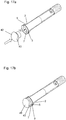
- Figure 2 shows the first attachment 2 comprising the gripping sleeve member 5 according to a first embodiment.
- the gripping sleeve member 5 consists of a first gripping sleeve member part 9.
- the gripping sleeve member 5 comprises an opening 10 for receiving the first member 6 of the operable drug delivery device 1.
- the opening 10 is arranged at one end of the gripping sleeve member 5.
- the gripping sleeve member 5 is closed at the end opposite of the opening 10.
- the first gripping sleeve member part 9 comprises a first part 11 comprising the opening 10 and stretching over roughly a third of the length of the first gripping sleeve member part 9.
- the first part 11 is a gripping part.
- the first part 11 comprises a structured surface 12 providing an increased friction and, thus, allowing for an easy grip of a patient.
- the structured surface 12 of the first part 9 comprises dot-shaped protrusions.
- the first gripping sleeve member part 9 comprises a part 13 that is at least partially transparent.
- the at least partially transparent part 13 is adjacent to the first part 11 in a direction away from the opening 10.
- the at least partially transparent part 13 of the first gripping sleeve member part 9 overlaps with the window 40 in the housing of the operable drug delivery device 1. Accordingly, the number shown in the window is visible when the gripping sleeve member 5 is attached to the operable drug delivery device 1.
- the first gripping sleeve member part 9 comprises a last part 14 which is adjacent to the at least partially transparent part 13 in a direction away from the opening 10.
- the last part 14 comprises the closed end.
- the radius of the gripping sleeve member 5 is greatest in the first part 11 near the opening 10 of the gripping sleeve member 5. In a sub-part of the first part 11 arranged at a distance from the opening 10 and in the other parts 13, 14 of the first gripping sleeve member part 9 the radius is constant.
- the gripping sleeve member 5 has a radius that is greater than the radius of the operable drug delivery device 1.
- the radius of the opening 10 of the gripping sleeve member 5 is greater than the radius of the operable drug delivery device 1 taken any point along a longitudinal axis 61 of the operable drug delivery device 1. Accordingly, the gripping sleeve member 5 is configured to at least partially receive the operable drug delivery device 1.
- Figure 3 shows the second attachment 3 comprising the guarding sleeve member 7.
- the guarding sleeve member 7 comprises a first opening 15 at one end and a second opening 16 at the opposite end.
- the first and the second opening 15, 16 are connected by a channel formed through the guarding sleeve member 7.
- a window 17 is defined in the guarding sleeve member 7.
- the at least partially transparent part 13 of the first gripping sleeve member part 9 overlaps the window 17 of the guarding sleeve member 7.
- the guarding sleeve member 7 comprises a contact surface 18 arranged at the first opening 15 of the guarding sleeve member 7.
- the contact surface 18 is circular shaped.
- the contact surface 18 of the guarding sleeve member 7 may abut the skin of the patient.
- the contact surface 18 of the guarding sleeve member 7 is bigger than the surface of the operable drug delivery device 1 that contacts the skin of the patient if the dose dispense operation is carried out with the operable drug delivery device 1 and without the guarding sleeve member 7.
- the contact surface 18 provides a more stable connection to the skin of the patient, thus increasing the usability of the kit and allowing a person with impaired finger dexterity to carry out the dose dispense operation.
- the guarding sleeve member 7 has a radius that is greater than the radius of the operable drug delivery device 1.
- the radius of the channel through the guarding sleeve member 7 is greater than the radius of the operable drug delivery device 1 taken any point along the longitudinal axis 61 of the operable drug delivery device 1. Accordingly, the guarding sleeve member 7 is configured to at least partially receive the operable drug delivery device 1.
- the radius of the gripping sleeve member 5 is greater than the radius of the guarding sleeve member 7. Accordingly, the gripping sleeve member 5 is configured to at least partially receive the guarding sleeve member 7. In particular, when both attachments 2, 3 are attached to the operable drug delivery device 1, the gripping sleeve member 5 partly receives the guarding sleeve member 7.
- Figure 4 shows a kit comprising the operable drug delivery device 1 and the second attachment 3 comprising the guarding sleeve member 7.
- the guarding sleeve member 7 is not attached to the operable drug delivery device 1.
- the distal end of the operable drug delivery device 1 is entered through the second opening 16 of the guarding sleeve member 7, as indicated in Figure 4 .
- Figure 5 shows the kit comprising the guarding sleeve member 7 and the operable drug delivery device 1 wherein the guarding sleeve member 7 is attached to the operable drug delivery device 1.
- the guarding sleeve member 7 receives a second member 8 of the operable drug delivery device 1.
- the second member 8 is the cartridge holder 19.
- the guarding sleeve member 7 When the guarding sleeve member 7 is attached to the operable drug delivery device 1, the guarding sleeve member 7 projects beyond the end of the operable drug delivery device 1 in the distal direction 4.
- Figure 6 shows a more detailed view of the engagement of the guarding sleeve member 7 with the second member 8 of the operable drug delivery device 1.
- the guarding sleeve member 7 is shown in a cross-sectional view.
- the guarding sleeve member 7 comprises an engagement feature 20 at its inner surface.
- the engagement feature 20 of the guarding sleeve member 7 comprises an indentation 21.
- the indentation 21 extends in a direction from the first opening 15 towards the second opening 16 of the guarding sleeve member 7.
- the indentation 21 is formed by a first wall 22 facing towards the first opening 15 and a second wall 23 facing towards the second opening 16.
- the first wall 22 defining the indentation 21 is formed as a smooth curve.
- the second wall 23 defining the indentation 21 is arranged at an angle in the range of 70° to 130° to the end of the first wall 22, thereby forming a sharp edge.
- the engagement feature 20 of the guarding sleeve member 7 defines a pull out end stop feature 24.
- the second wall 23 formed as a sharp edge defines the pull out end stop feature 24.
- the pull out end stop feature 24 prevents an axial movement of the guarding sleeve member 7 relative to the second member 8 in the distal direction 4 when the guarding sleeve member 7 is engaged with the second member 8.
- the second member 8 of the operable drug delivery device 1 comprises a corresponding engagement feature 25.
- the engagement feature 25 of the second member 8 comprises a protrusion 26.
- the engagement feature 25 of the second member 8 has a distal face 27 and a proximal face 28.
- the distal face 27 of the engagement feature 25 of the second member 8 is arranged at a smooth angle relative to the longitudinal axis 61 of the operable drug delivery device 1 in the range of 5° to 60°. Accordingly, the distal face 27 of the engagement feature 25 of the second member 8 is formed such that the guarding sleeve member 7 is allowed to slide over the engagement feature 25 of the second member 8 in a proximal direction 62.
- proximal face 28 of the engagement feature 25 of the second member 8 is tapered relative to the longitudinal axis 61 of the operable drug delivery device 1 in a steep angle, e.g. an angle in the range of 80° to 150°. Accordingly, the proximal face 28 of the engagement feature 25 of the second member 8 is formed such that the guarding sleeve member 7 is prevented from sliding over the engagement feature 25 of the second member 8 in the distal direction 4 once the engagement features 20, 25 of the guarding sleeve member 7 and of the second member 8 are engaged with each other.
- the engagement features 20, 25 of the guarding sleeve member 7 and of the second member 8 are configured to be engaged with each other by a snap-fit connection.
- engagement features 20, 25 of the guarding sleeve member 7 and of the second member 8 are engaged with each other, the guarding sleeve member 7 is prevented from rotating or moving axially relative to the second member 8 of the operable drug delivery device 1.
- the guarding sleeve member 7 comprises a push in end stop feature 29 which limits the distance by which the second member 8 of the operable drug delivery device 1 can be moved relative to the guarding sleeve member 7 in the distal direction 4.
- the push in end stop feature 29 comprises an abutment surface 30.
- the second member comprises a corresponding abutment surface 31.
- the guarding sleeve member 7 is dimensioned such that the push in end stop feature 29 abuts the abutment surface 31 of the second member 8 in the relative position in which the engagement features 20, 25 of the guarding sleeve member 7 and the second member 8 are engaged with each other. Thus, the guarding sleeve member 7 is prevented from moving axially relative to the second member 8 of the operable drug delivery device 1 in this position.
- the engagement features 20, 25 of the guarding sleeve member 7 and of the second member 8 are configured such that a rotational movement of the guarding sleeve member 7 relative to the second member 8 is prevented when the engagement features 20, 25 are engaged with each other.
- the engagement features 20, 25 are not rotary symmetric.
- Figure 7 shows the kit comprising the operable drug delivery device 1, the first attachment 2 comprising the gripping sleeve member 5 and the second attachment 3 comprising the guarding sleeve member 7.
- the guarding sleeve member 7 is engaged with the second member 8 of the operable drug delivery device 1.
- the gripping sleeve member 5 is not attached to the operable drug delivery device 1.
- the operable drug delivery device 1 is inserted into the opening 10 of the gripping sleeve member 5.
- Figure 8 shows the gripping sleeve member 5 being attached to the operable drug delivery device 1.
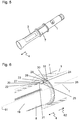
- FIG 9 shows a detailed cross-sectional view of the gripping sleeve member 5 being attached to the operable drug delivery device 1.
- the gripping sleeve member 5 comprises an engagement feature 32.
- the engagement feature 32 of the gripping sleeve member 5 is arranged at an inner surface of the gripping sleeve member 5.
- the engagement feature 32 of the gripping sleeve member 5 is arranged at an end opposite to the opening 10 of the gripping sleeve member 5.
- the engagement feature 32 of the gripping sleeve member 5 comprises a projecting element 33.
- the first member 6 of the operable drug delivery device 1 comprises an engagement feature 34.
- the engagement feature 32 of the gripping sleeve member 5 is configured to be engaged with the engagement feature 34 of the first member 6.
- the engagement feature 34 of the first member 6 comprises a recess 35.
- the engagement features 32, 34 of the gripping sleeve member 5 and of the first member 6 are configured to be engaged with each other by a snap-fit engagement.
- a dose setting operation and a dose dispense operation is considered for the operable drug delivery device 1 not being engaged with the first or the second attachment 2, 3.
- the user has to rotate the first member 6, i.e. the dose dial member, relative to the body.
- the dose dial member is concurrently moved in the proximal direction 62 relative to the housing of the operable drug delivery device 1.
- the user has to push the dose dial member in the distal direction 4 relative to the housing.
- Figure 10 shows a dose setting operation for a kit comprising the operable drug delivery device 1, the first attachment 2 and the second attachment 3.
- the user rotates the gripping sleeve member 5 relative to the guarding sleeve member 7.
- the first member 6 in this case the dose dial member
- the second member 8 i.e. the cartridge holder
- the first member 6 is thereby rotated relative to the second member 8.
- the first member 6 is also moved in the proximal direction 62 relative to the second member 8.
- the gripping sleeve member 5 is moved in the proximal direction relative to the guarding sleeve member 7.
- Figure 11 shows the dose delivery operation for the kit.
- the gripping sleeve member 5 is moved axially in the distal direction 4 relative to the guarding sleeve member 7.
- the axial movement of the gripping sleeve member 5 is transferred into an axial movement of the first member 6 relative to the second member 8 and thus, a dose is delivered.
- Figure 12 shows the first attachment 2 according to a second embodiment.
- the gripping sleeve member 5 comprises the first gripping sleeve member part 9 and a second gripping sleeve member part 36.
- the first gripping sleeve member part 9 comprises the engagement features 34 (not shown in Figure 12 ) at its inner surface.
- the first gripping sleeve member part 9 is rotatable relative to the second gripping sleeve member part 36. Further, the first gripping sleeve member part 9 is prevented from moving axially relative to the second gripping sleeve member part 36.
- the second gripping sleeve member part 36 comprises the opening 10 of the gripping sleeve member 5.
- the second gripping sleeve member part 36 comprises a first alignment feature 37.
- the alignment feature 37 comprises a slot at an inner surface of the second gripping sleeve member part 36.
- Figure 13 shows the second attachment 3 comprising the guarding sleeve member 7 according to the second embodiment.
- Figures 14 and 15 show an engagement of the gripping sleeve member 5 with a kit comprising the operable drug delivery device 1 and the second attachment 3.
- the operable drug delivery device 1 comprises a second alignment feature 38.
- a lens 39 covering the window 40 in the housing 41 of the operable drug delivery device 1 forms a protrusion which forms the second alignment feature 38.
- the first alignment feature 37 of the second gripping sleeve member part 36 cooperates with the second alignment feature 38 of the operable drug delivery device 1.
- first and the second alignment features 37, 38 are engaged with each other, an axial movement of the second gripping sleeve member part 36 relative to the housing 41 of the operable drug delivery device 1 is permitted.
- the first and second alignment feature 37, 38 being engaged with each other prevent a rotation of the second gripping sleeve member part 36 relative to the housing 41 of the operable drug delivery device 1.
- the guarding sleeve member 7 may comprise the second alignment feature 38.
- the second alignment feature 38 may be formed by a protrusion of the guarding sleeve member 38 being configured to be engaged with the first alignment feature 37 of the second gripping sleeve member part 36.
- An engagement of the first alignment feature 37 of the second gripping sleeve member part 36 with the second alignment feature 38 of the guarding sleeve member 7 provides a rotational constrain for the second gripping sleeve member part 36. In particular, thereby, a rotation of the second gripping sleeve member part 36 relative to the guarding sleeve member 7 may be prevented.
- the second alignment feature 38 is formed by the guarding sleeve member 7, the lens 39 of the operable drug delivery device 1 is better protected against being damaged by the first alignment feature 37 in case of a misuse.
- Figure 16 shows a cap member 42 being engageable to the guarding sleeve member 7.
- Figure 17 shows the cap member 42 being engaged to the kit comprising the operable drug delivery device 1, the first attachment 2 and the second attachment 3.
- the first opening 15 of the guarding sleeve member 7 defines an opening of the kit at the distal end.
- the cap member 42 is configured to close the opening 15 by engaging with the guarding sleeve member 7.
- the cap member 42, the first attachment 2 and the second attachment 3 form a cavity configured to receive the operable drug delivery device 1 such that the operable drug delivery device 1 may be arranged in the cavity. Accordingly, the cap member 42 allows the kit to be transported by a user in the same way as a normal drug delivery device is carried.
- the cap member 42 has a diameter which is larger than the diameter of the operable drug delivery device 1.
- the cap member 42 comprises curved edge features 43. The curved edge features 43 allow easily gripping the cap member 42. Accordingly, the cap member 42 can easily be attached to the guarding sleeve member 7 and removed from the guarding sleeve member 7, even by persons with impaired finger dexterity.
- Figure 18 shows a dose setting operation in the kit according to the second embodiment. Further, Figure 19 shows the kit before a dose is set and Figure 20 shows the kit after the dose is set.
- the first gripping sleeve member part 9 is rotated relative to the second gripping sleeve member part 36.
- the first member 6 of the operable drug delivery device 1, i.e. the dose dial member, is rotationally locked to the first gripping sleeve member part 9.
- the second gripping sleeve member part 36 is prevented from rotating relative to the housing 41 of the operable drug delivery device 1 due to the engagement of the first and the second alignment feature 37, 38. Accordingly, a rotation of the first gripping sleeve member part 9 relative to the second gripping sleeve member part 36 results in the first member 6 of the operable drug delivery device 1 being rotated relative to the housing 41 of the operable drug delivery device 1.
- first member 6 is concurrently to its rotational movement moved axially in the proximal direction 62 relative to the housing 41.
- first gripping sleeve member part 9 also moves axially in the proximal direction 62 relative to the second gripping sleeve member part 36.
- first gripping sleeve member part 9 moves axially in the proximal direction 62 relative to the housing 41.
- first gripping sleeve member part 9 moves axially in the proximal direction 62 relative to the second attachment 3.
- the second gripping sleeve member part 36 does not rotate relative to the housing 41 of the operable drug delivery device 1.
- the second gripping sleeve member part 36 moves out axially in the proximal direction 62 relative to the housing 41 of the operable drug delivery device 1 because the second gripping sleeve member part 36 is connected to the first gripping sleeve member part 9 such that a relative axial movement between the first and the second gripping sleeve member part 9, 36 is prevented.
- the second gripping sleeve member part 36 is moved from a first position to a second position relative to the housing 41 wherein the second position is proximal to the first position.
- the first position corresponds to no dose being set and the second position corresponds to a dose set position.
- the second gripping sleeve member part 36 comprises the at least partially transparent part 13 of the gripping sleeve member 5.
- the at least partially transparent part 13 of the gripping sleeve member 5 overlaps the window 40 in the housing 41 of the operable drug delivery device 1.
- the at least partially transparent part 13 overlaps the window 40 in each of the first and the second position of the second gripping sleeve member part 36.
- a window 44 may be defined in the second gripping sleeve member part 36.
- the window 44 in the second gripping sleeve member part 36 remains in overlap with the window 40 in the housing 41 of the operable drug delivery device 1 because the window 44 is designed sufficiently big.
- the guarding sleeve member 7 moves relative to the gripping sleeve member 5 in the distal direction 4.
- Figure 21 shows the kit in a state wherein the dose is set.
- the first attachment 2 is shown in a cross-sectional view in Figure 21 .
- the first member 6 of the operable drug delivery device 1 is arranged in a distance axially away from the housing 41 of the operable drug delivery device 1.
- Figures 22 and 23 show a dose dispense operation of the kit.
- the gripping sleeve member 5 is moved axially in the distal direction 4 relative to the guarding sleeve member 7.
- the axial motion of the first gripping sleeve member part 9 is transferred into a movement of the first member 6 and a dose is thereby delivered.
- the second gripping sleeve member part 36 follows the axial movement of the first gripping sleeve member part 9.
- the second gripping sleeve member part 36 does not rotate during the dose dispense operation.
- the second gripping sleeve member part 36 can comfortably be held in a full hand grip.
- Figure 24 shows the kit comprising the operable drug delivery device 1 and the two attachments 2, 3 according to a third embodiment.
- the first and the second attachment 2, 3 are shown in an exploded view.
- the guarding sleeve member 7 of the second attachment 3 comprises a first guarding sleeve member part 45 and a second guarding sleeve member part 46.
- the first and the second guarding sleeve member parts 45, 46 each comprised a thread 47 such that the first and the second guarding sleeve member parts 45, 46 are configured to be threadedly engaged with each other.
- Figure 25 shows an engagement of the guarding sleeve member 7 according to the third embodiment to the operable drug delivery device 1.
- the first and the second guarding sleeve member parts 45, 46 are each be inserted on either side of the operable drug delivery device 1 and than to threadedly engaged with each other.
- the first and the second guarding sleeve member part 45, 46 are dimensioned such that the guarding sleeve member 7 and the operable drug delivery device 1 are prevented from moving axially relative to each other when the first and the second guarding sleeve member part 45, 46 are engaged with each other.
- the second guarding sleeve member part 46 comprises a slot (not shown).
- the lens 39 of the drug delivery device 1 engages with the slot in the second guarding sleeve member part 46 to restrain a rotational movement of the guarding sleeve member 7 relative to the operable drug delivery device 1 when the first and the second guarding sleeve member parts 45, 46 are engaged with each other.
- the third embodiment of the kit may be combined with the guarding sleeve member 7 according to the previous embodiments.
- This guarding sleeve member 7 consists only of the first guarding sleeve member part 45 which is engageable with the second member 7 by an engagement of the engagement features 20, 25.
- Figure 26 shows the operable drug delivery device 1 with the guarding sleeve member 7 attached.
- Figure 27 shows the first attachment 2 according to the third embodiment.
- the operable drug delivery device 1 is moved into the opening 10 of the gripping sleeve member 5.
- the guarding sleeve member 7 comprises a first orientation member 48. Further, the second gripping sleeve member part 36 comprises a second orientation member 49.
- the first orientation member 48 of the guarding sleeve member 7 is a protrusion arranged at an outer surface of the guarding sleeve member 7.
- the protrusion extends in an axial direction parallel to a longitudinal axis of the guarding sleeve member 7.
- the second orientation member 49 of the second gripping sleeve member part 36 is a slot arranged at an inner surface of the second gripping sleeve member part 36.
- the first and the second orientation member 48, 49 are configured to be engageble with each other only when the guarding sleeve member 7 and the second gripping sleeve member part 36 are oriented relative to each other in a predetermined rotational position. Further, an engagement of the first and the second orientation member 48, 49 prevents a relative rotational movement between the guarding sleeve member 7 and the second gripping sleeve member part 36.
- Figure 24 shows the first gripping sleeve member part 9 comprising a button 63 and a button sleeve 64.
- the button and the button sleeve may be formed integrally by a single piece.
- the first attachment 2 further comprises a spring member 50. Further, the first attachment 2 comprises a torque limiting mechanism 51.
- the torque limiting mechanism 51 defines a maximum allowed torque.
- the torque limiting mechanism 51 comprises a clutch member 52.
- the clutch member 52 and the spring member 50 are arranged between the first and the second gripping sleeve member part 9, 36. When the first attachment 2 is assembled to the operable drug delivery device, the clutch member 52 abuts an inner surface of the first gripping member part 9 and an outer surface of the first member 6.
- the clutch member 52 comprises an engagement feature 53, e.g. a clutch arm.
- the engagement feature 53 of the clutch member 52 may be configured to engage with the engagement feature 34 of the first member 6 of the operable drug delivery device 1.
- the engagement features 53 of the clutch member 52 and of the first member 6 are configured to be connected by a snap-fit connection.
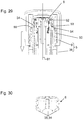
- Figure 28 shows a cross sectional view of the kit according to the third embodiment wherein the first attachment 2 is attached to the operable drug delivery device 1.
- the operable drug delivery device 1 To engage the first attachment 2 with the first member 6 of the operable drug delivery device 1, the operable drug delivery device 1 is moved into the opening 10 of the first attachment 2. When the first member 6 abuts the clutch member 52, the first member 6 distorts the engagement feature 53 of the clutch member 52. In particular, the first member 6 moves the engagement features 53 of the clutch member 52 outwards in a direction away from the longitudinal axis 61 of the operable drug delivery device 1. When the first member 6 is moved further in the proximal direction 62 relative to the clutch member 52, the engagement feature 53 of the clutch member 52 engages the engagement feature 34 of the first member 6, thereby preventing a further rotational or axial movement of the first member 6 and the clutch member 52.
- the engagement feature 53 of the clutch member 52 snaps into a snap-fit engagement with the engagement feature 34 of the first member 6.
- the clutch arms are snap fitted into the recess 35 of the first member 6.
- the spring member 50 is arranged such that one end of the spring member 50 abuts the clutch member 52 and the other end of the spring member 53 abuts the second gripping sleeve member part 36.
- the spring member 50 exerts a force on the clutch member 52 in a direction away from the second gripping sleeve member part 36, thereby ensuring constant contact between the clutch member 52 and the first member 6.
- the third embodiment is configured such that the gripping sleeve member 5 may be disengaged from the first member 6 of the drug delivery device 1 without damaging one of the members of the kit.
- the first attachment 2 comprises a first disengagement feature 54.
- the first disengagement feature 54 has a first and a second position.
- Figure 28 shows the kit in a state wherein the first disengagement feature 54 is in its first position.
- Figure 29 shows the kit when the first disengagement feature 54 is moved into its second position.
- the first disengagement feature 54 is a feature of the clutch member 52.
- the first disengagement feature 54 is formed by a tapered end face of the engagement feature 53 of the clutch member 52.
- the first disengagement feature 54 may be a feature of the first gripping sleeve member part 9.
- the first gripping sleeve member part 9 may have a tapered surface forming the first disengagement feature 54.
- the first disengagement feature 54 is configured not to disengage the gripping sleeve member 5 from the first member 6 of the operable drug delivery device 1.
- the first position corresponds to the engagement feature 53 of the clutch member 52 not being bent outwards in a direction away from the longitudinal axis 61 of the operable drug delivery device 1.
- the first disengagement feature 54 is configured to disengage the gripping sleeve member 5 from the first member 6 of the operable drug delivery device 1.
- the second position of the first disengagement feature 54 corresponds to the engagement feature 53 of the clutch member 52 being disengaged from the engagement feature 34 of the first member 6. Accordingly, the clutch arms are bent outwards in a radial direction away from the longitudinal axis 61 of the operable drug delivery device 1.
- the spring member 50 applying a force onto the clutch member 52 in a direction away from the second gripping sleeve member part 36 tends to move the disengagement feature 54 into its first position.
- the first and the second gripping sleeve member parts 9, 36 have to be moved towards each other overcoming the force applied by the spring member 50.
- the second gripping sleeve member part 36 comprises a second disengagement feature 55.
- the second disengagement feature 55 is formed by a tapered surface of the second gripping sleeve member part 36.
- the tapered surface is arranged at a distance towards the first disengagement feature 54 in the first position of the first disengagement feature 54.
- the second gripping sleeve member part 36 is configured such that an axial movement of the first gripping sleeve member part 9 towards the second gripping sleeve member part 36 engages the second disengagement feature 55 to the first disengagement feature 54, thereby moving the first disengagement feature 54 into its second position. This is shown in Figure 29 .
- the spring member 50 pushes the clutch member 52 in the proximal direction, thereby moving the first gripping sleeve member part 9 away from the operable drug delivery device 1 and releasing the engagement of the first gripping sleeve member part 9 and the clutch member 52 to the operable drug delivery device 1. Further, the engagement of the second gripping sleeve member part 36 with the operable drug delivery device 1 is also released.
- the dose setting and the dose delivery operation are carried out in the same way as described above with respect to the first embodiment.
- a dose is set by rotating the first gripping sleeve member part 9 relative to the second gripping sleeve member part 36.
- the guarding sleeve member 7 moves relative to the gripping sleeve member 5 in the distal direction 4. Due to the engagement of the orientation features 48, 49 between the guarding sleeve member 7 and the second gripping sleeve member part 36, the second gripping sleeve member part 36 and the guarding sleeve member 7 can only move axially relative to each other.
- Figure 30 shows the first member 6 of the operable drug delivery device 1.
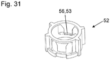
- Figure 31 shows the clutch member 52.
- the clutch member 52 comprises a projection 56 at its inner surface that is in abutment with the recess 35 of the first member 6 of the operable drug delivery device 1.
- the projection 56 of the clutch member 52 fits into the recessed part 35 of the first member 6 enabling a transmission of the rotational movement of the first gripping sleeve member part 9 to the clutch member 52 and then to the first member 6 of the operable drug delivery device 1.
- the projection 56 of the clutch member 52 corresponds to the engagement feature 53 of the clutch member 52.
- the recess 35 of the first member 6 corresponds to the engagement feature 34 of the first member 6.
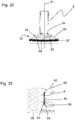
- Figure 32 shows an engagement of the engagement feature 53 of the clutch member 52 with the engagement feature 34 of the first member 6.
- Each of the engagement feature 53 of the clutch member 52 and the engagement feature 34 of the first member 6 has a face 58, 59 which is arranged in an angle relative to the longitudinal axis of the drug delivery device 1 in the range of 10 to 80° when the first attachment 2 is attached to the operable drug delivery device 1.
- Figure 33 shows the clutch member 52 and the first member 6 being engaged with each other.
- Figure 34 shows the clutch member 52 and the first member 6 being disengaged from each other.
Claims (15)
- Fixation (2) pour un dispositif d'administration de médicament (1) commandable, le dispositif d'administration de médicament (1) commandable étant entièrement commandable sans la fixation (2), comprenant un organe de manchon de préhension (5) qui est configuré pour recevoir un premier organe (6) du dispositif d'administration de médicament (1) commandable,
l'organe de manchon de préhension (5) comprenant une première partie d'organe de manchon de préhension (9) comprenant un premier élément d'engagement (32) au niveau de sa surface intérieure, qui est configuré pour mettre en prise la première partie d'organe de manchon de préhension (9) de manière fixée en torsion avec le premier organe (6) du dispositif d'administration de médicament (1) commandable, et la fixation (2) comprenant un mécanisme limiteur de couple (51) définissant un couple maximum admissible empêchant l'endommagement du premier organe (6) du dispositif d'administration de médicament (1) commandable sous l'effet d'un couple excessif appliqué à la première partie d'organe de manchon de préhension (9),
caractérisée en ce que
la fixation (2) comprend un organe de ressort (50) fournissant une force de ressort ayant tendance à déplacer la première partie d'organe de manchon de préhension (9) en prise avec le premier organe (6) du dispositif d'administration de médicament (1) commandable. - Fixation (2) selon la revendication précédente, dans laquelle la première partie d'organe de manchon de préhension (9) est accouplée au premier organe (6) du dispositif d'administration de médicament (1) commandable par le biais du mécanisme limiteur de couple (51) qui est configuré pour empêcher qu'un mouvement de la première partie d'organe de manchon de préhension (9) ne soit transféré à un mouvement du premier organe (6) si un couple appliqué à la première partie d'organe de manchon de préhension (9) est supérieur au couple maximum admissible.
- Fixation (2) selon la revendication 2,
dans laquelle le mécanisme limiteur de couple (51) comprend un organe d'embrayage (52) configuré pour patiner lorsqu'un couple supérieur au couple maximum admissible est appliqué à la première partie d'organe de manchon de préhension (9). - Fixation (2) selon l'une des revendications précédentes,
dans laquelle l'organe de manchon de préhension (5) comprend une ouverture (10) pour recevoir le premier organe (6) du dispositif d'administration de médicament (1) commandable et
dans laquelle le premier élément d'engagement (32) est disposé à une extrémité de l'organe de manchon de préhension (5) opposée à l'ouverture (10). - Fixation (2) selon l'une des revendications précédentes,
dans laquelle le premier élément d'engagement (32) est configuré pour mettre en prise la première partie d'organe de manchon de préhension (9) de manière libérable avec le premier organe (6) du dispositif d'administration de médicament (1) commandable. - Fixation (2) selon l'une des revendications précédentes,
dans laquelle l'organe de manchon de préhension (5) comprend une deuxième partie d'organe de manchon de préhension (36) qui est apte à tourner par rapport à la première partie d'organe de manchon de préhension (9) et qui ne peut pas se déplacer axialement par rapport à la première partie d'organe de manchon de préhension (9). - Fixation (2) selon la revendication 5,
dans laquelle l'organe de manchon de préhension (5) comprend une deuxième partie d'organe de manchon de préhension (36) qui comprend un élément de désengagement (55),
l'élément de désengagement (55) étant configuré pour désengager l'engagement libérable de la première partie d'organe de manchon de préhension (9) avec le premier organe (6) lorsque la première partie d'organe de manchon de préhension (9) est déplacée par rapport à la deuxième partie d'organe de manchon de préhension (36). - Système de fixations (2, 3) pour un dispositif d'administration de médicament (1) commandable, comprenant une fixation (2) selon l'une des revendications précédentes et comprenant en outre un organe de manchon de protection (7) qui est configuré pour être attaché au dispositif d'administration de médicament (1) commandable et pour recevoir un deuxième organe (8) du dispositif d'administration de médicament (1) commandable.
- Système selon la revendication 8,
dans lequel la fixation est une fixation selon l'une des revendications 6 et 7,
dans lequel l'organe de manchon de protection (7) comprend un premier organe d'orientation (48) et la deuxième partie d'organe de manchon de préhension (36) comprend un deuxième organe d'orientation (49), et
dans lequel le premier et le deuxième organe d'orientation (48, 49) sont configurés pour pouvoir être mis en prise l'un avec l'autre seulement lorsque l'organe de manchon de protection (7) et la deuxième partie d'organe de manchon de préhension (36) sont orientés l'un par rapport à l'autre dans une position de rotation relative prédéterminée. - Système selon la revendication 8 ou 9,
comprenant en outre un organe de capuchon (42) qui peut être mis en prise avec l'organe de manchon de protection (7) et qui est configuré pour fermer une ouverture (15) de l'organe de manchon de protection (7) lorsqu'il est mis en prise avec l'organe de manchon de protection (7). - Système selon l'une des revendications 9 et 10, dans lequel l'organe de manchon de préhension (5) est configuré pour recevoir au moins en partie l'organe de manchon de protection (7).
- Kit comprenant une fixation (2) pour un dispositif d'administration de médicament (1) commandable ou un système de fixations (2, 3) pour un dispositif d'administration de médicament (1) commandable selon l'une des revendications précédentes et un dispositif d'administration de médicament (1) commandable comprenant le premier organe (6) et un deuxième organe (8).
- Kit selon la revendication 12,
dans lequel le premier organe (6) comprend un organe de sélection de dose qui est configuré pour être tourné par rapport au deuxième organe (8) du dispositif d'administration de médicament (1) commandable au cours d'une opération de réglage de dose et/ou au cours d'une opération de distribution de dose du dispositif d'administration de médicament (1) commandable. - Kit selon l'une des revendications 12 et 13,
dans lequel le premier organe (6) comprend un deuxième élément d'engagement (34) et
dans lequel le deuxième élément d'engagement (34) du premier organe et le premier élément d'engagement (32) de l'organe de manchon de préhension (5) sont configurés pour être connectés l'un à l'autre par une connexion par encliquetage. - Utilisation de la fixation (2) selon l'une des revendications 1 à 7 ou du système de fixations (2, 3) selon l'une des revendications 8 à 12 pour commander un dispositif d'administration de médicament (1) commandable.
Priority Applications (1)
| Application Number | Priority Date | Filing Date | Title |
|---|---|---|---|
| EP14709251.4A EP2968778B1 (fr) | 2013-03-13 | 2014-03-10 | Poignée additionnelle et manchon d'actionnement pour un dispositif d'injection de médicaments du type stylo |
Applications Claiming Priority (3)
| Application Number | Priority Date | Filing Date | Title |
|---|---|---|---|
| EP13159056 | 2013-03-13 | ||
| EP14709251.4A EP2968778B1 (fr) | 2013-03-13 | 2014-03-10 | Poignée additionnelle et manchon d'actionnement pour un dispositif d'injection de médicaments du type stylo |
| PCT/EP2014/054533 WO2014139921A1 (fr) | 2013-03-13 | 2014-03-10 | Poignée additionnelle et manchon d'actionnement pour un dispositif d'injection de médicaments du type stylo |
Publications (2)
| Publication Number | Publication Date |
|---|---|
| EP2968778A1 EP2968778A1 (fr) | 2016-01-20 |
| EP2968778B1 true EP2968778B1 (fr) | 2020-07-22 |
Family
ID=47891453
Family Applications (1)
| Application Number | Title | Priority Date | Filing Date |
|---|---|---|---|
| EP14709251.4A Active EP2968778B1 (fr) | 2013-03-13 | 2014-03-10 | Poignée additionnelle et manchon d'actionnement pour un dispositif d'injection de médicaments du type stylo |
Country Status (6)
| Country | Link |
|---|---|
| US (1) | US9956347B2 (fr) |
| EP (1) | EP2968778B1 (fr) |
| JP (1) | JP6377649B2 (fr) |
| CN (1) | CN105025959B (fr) |
| HK (1) | HK1213514A1 (fr) |
| WO (1) | WO2014139921A1 (fr) |
Families Citing this family (12)
| Publication number | Priority date | Publication date | Assignee | Title |
|---|---|---|---|---|
| CN107206176B (zh) * | 2015-02-10 | 2020-08-25 | 赛诺菲-安万特德国有限公司 | 用于药剂注射装置的放大装置 |
| USD810282S1 (en) * | 2015-10-19 | 2018-02-13 | Carebay Europe Ltd | Medical injector |
| USD818575S1 (en) * | 2015-12-08 | 2018-05-22 | Becton Dickinson France S.A.S. | Medical injector with enhanced grip |
| JP6856840B2 (ja) | 2016-12-27 | 2021-04-14 | アクション メディカル テクノロジーズ,エルエルシーAction Medical Technologies,Llc | 注入器、および注入器を動作させる方法 |
| CN111107894B (zh) | 2017-09-22 | 2022-07-12 | 诺和诺德股份有限公司 | 用于药物递送装置的附属装置 |
| EP3720525A1 (fr) | 2017-12-04 | 2020-10-14 | Novo Nordisk A/S | Système d'administration de médicament comprenant un aimant multipolaire et un système de capteur |
| CN108378896A (zh) * | 2018-01-11 | 2018-08-10 | 恩脉(上海)医疗科技有限公司 | 用于介入治疗的疏通导管 |
| US11224696B2 (en) | 2018-07-10 | 2022-01-18 | Action Medical Technologies, Llc | Apparatuses and method for injecting medicaments |
| USD893712S1 (en) | 2019-02-15 | 2020-08-18 | Action Medical Technologies, Llc | Grip for autoinjectors |
| EP3952956A1 (fr) * | 2019-04-09 | 2022-02-16 | Amgen Inc. | Dispositif d'administration de médicament à poignée intelligente |
| JP7323240B2 (ja) | 2020-03-25 | 2023-08-08 | アクション メディカル テクノロジーズ,エルエルシー | 薬剤を注入するための装置および方法 |
| US11759576B2 (en) | 2020-06-05 | 2023-09-19 | Action Medical Technologies, Llc | Parenteral injection apparatus |
Family Cites Families (37)
| Publication number | Priority date | Publication date | Assignee | Title |
|---|---|---|---|---|
| US533575A (en) | 1895-02-05 | wilkens | ||
| US5226895A (en) | 1989-06-05 | 1993-07-13 | Eli Lilly And Company | Multiple dose injection pen |
| GB9007113D0 (en) | 1990-03-29 | 1990-05-30 | Sams Bernard | Dispensing device |
| ES2074771T3 (es) | 1991-07-24 | 1995-09-16 | Medico Dev Investment Co | Inyector. |
| DK175491D0 (da) | 1991-10-18 | 1991-10-18 | Novo Nordisk As | Apparat |
| US5279586A (en) | 1992-02-04 | 1994-01-18 | Becton, Dickinson And Company | Reusable medication delivery pen |
| US5320609A (en) | 1992-12-07 | 1994-06-14 | Habley Medical Technology Corporation | Automatic pharmaceutical dispensing syringe |
| US5383865A (en) * | 1993-03-15 | 1995-01-24 | Eli Lilly And Company | Medication dispensing device |
| ZA941881B (en) | 1993-04-02 | 1995-09-18 | Lilly Co Eli | Manifold medication injection apparatus and method |
| US5582598A (en) | 1994-09-19 | 1996-12-10 | Becton Dickinson And Company | Medication delivery pen with variable increment dose scale |
| CA2213682C (fr) | 1995-03-07 | 2009-10-06 | Eli Lilly And Company | Distributeur recyclable de medicament |
| US5674204A (en) | 1995-09-19 | 1997-10-07 | Becton Dickinson And Company | Medication delivery pen cap actuated dose delivery clutch |
| US5688251A (en) | 1995-09-19 | 1997-11-18 | Becton Dickinson And Company | Cartridge loading and priming mechanism for a pen injector |
| AU7331598A (en) | 1997-07-11 | 1999-02-08 | Novo Nordisk A/S | An apparatus for the registration of the setting of a medical device |
| DE19730999C1 (de) | 1997-07-18 | 1998-12-10 | Disetronic Licensing Ag | Dosierknopfsicherung an einer Vorrichtung zur dosierten Verabreichung eines injizierbaren Produkts |
| US5957896A (en) * | 1997-08-11 | 1999-09-28 | Becton, Dickinson And Company | Medication delivery pen |
| EP1003581B1 (fr) | 1998-01-30 | 2000-11-08 | Novo Nordisk A/S | Seringue d'injection |
| US6221053B1 (en) | 1998-02-20 | 2001-04-24 | Becton, Dickinson And Company | Multi-featured medication delivery pen |
| US5961495A (en) | 1998-02-20 | 1999-10-05 | Becton, Dickinson And Company | Medication delivery pen having a priming mechanism |
| US6248095B1 (en) | 1998-02-23 | 2001-06-19 | Becton, Dickinson And Company | Low-cost medication delivery pen |
| AU6892100A (en) | 1999-08-05 | 2001-03-05 | Becton Dickinson & Company | Medication delivery pen |
| US6277099B1 (en) * | 1999-08-06 | 2001-08-21 | Becton, Dickinson And Company | Medication delivery pen |
| US6319224B1 (en) | 1999-08-20 | 2001-11-20 | Bioject Medical Technologies Inc. | Intradermal injection system for injecting DNA-based injectables into humans |
| GB0007071D0 (en) * | 2000-03-24 | 2000-05-17 | Sams Bernard | One-way clutch mechanisms and injector devices |
| US6663602B2 (en) | 2000-06-16 | 2003-12-16 | Novo Nordisk A/S | Injection device |
| US6899699B2 (en) | 2001-01-05 | 2005-05-31 | Novo Nordisk A/S | Automatic injection device with reset feature |
| EP2258425B1 (fr) | 2001-05-16 | 2013-01-30 | Eli Lilly and Company | Appareil injecteur de médication |
| GB0304823D0 (en) | 2003-03-03 | 2003-04-09 | Dca Internat Ltd | Improvements in and relating to a pen-type injector |
| DE102004063644A1 (de) | 2004-12-31 | 2006-07-20 | Tecpharma Licensing Ag | Vorrichtung zur dosierten Verabreichung eines fluiden Produkts mit Drehfederantrieb |
| DE202006014996U1 (de) * | 2006-09-28 | 2008-02-14 | Voco Gmbh | Spritze zum dosierten Abgeben von Werkstoffen, insbesondere von dentalen Werkstoffen |
| US20080306434A1 (en) * | 2007-06-08 | 2008-12-11 | Dexcom, Inc. | Integrated medicament delivery device for use with continuous analyte sensor |
| US8647309B2 (en) | 2008-05-02 | 2014-02-11 | Sanofi-Aventis Deutschland Gmbh | Medication delivery device |
| CA2743571C (fr) * | 2008-11-17 | 2018-01-02 | Becton, Dickinson And Company | Dispositif de force additionnelle destine a un stylo de distribution de medicaments pour une injection intradermique de medicaments |
| WO2010098931A1 (fr) * | 2009-02-27 | 2010-09-02 | Lifescan, Inc. | Systèmes et procédés de gestion de distribution de médicaments |
| WO2011057677A1 (fr) | 2009-11-16 | 2011-05-19 | Tecpharma Licensing Ag | Dispositif d'administration pourvu d'une protection de surcharge pour le dosage |
| US9694138B2 (en) * | 2010-07-02 | 2017-07-04 | Sanofi-Anetis Deutschland GMBH | Safety device for a pre-filled syringe, injection device and injection kit |
| JP5974016B2 (ja) * | 2011-11-10 | 2016-08-23 | パナソニックヘルスケアホールディングス株式会社 | 薬剤注入装置 |
-
2014
- 2014-03-10 JP JP2015562063A patent/JP6377649B2/ja active Active
- 2014-03-10 US US14/770,851 patent/US9956347B2/en active Active
- 2014-03-10 WO PCT/EP2014/054533 patent/WO2014139921A1/fr active Application Filing
- 2014-03-10 EP EP14709251.4A patent/EP2968778B1/fr active Active
- 2014-03-10 CN CN201480011785.0A patent/CN105025959B/zh active Active
-
2016
- 2016-02-11 HK HK16101483.4A patent/HK1213514A1/zh unknown
Non-Patent Citations (1)
| Title |
|---|
| None * |
Also Published As
| Publication number | Publication date |
|---|---|
| JP6377649B2 (ja) | 2018-08-22 |
| US9956347B2 (en) | 2018-05-01 |
| EP2968778A1 (fr) | 2016-01-20 |
| US20160008546A1 (en) | 2016-01-14 |
| JP2016509904A (ja) | 2016-04-04 |
| CN105025959A (zh) | 2015-11-04 |
| HK1213514A1 (zh) | 2016-07-08 |
| CN105025959B (zh) | 2019-04-19 |
| WO2014139921A1 (fr) | 2014-09-18 |
Similar Documents
| Publication | Publication Date | Title |
|---|---|---|
| US11813438B2 (en) | Drug delivery device | |
| EP2968778B1 (fr) | Poignée additionnelle et manchon d'actionnement pour un dispositif d'injection de médicaments du type stylo | |
| US11426528B2 (en) | Injection device | |
| US9427527B2 (en) | Fixed-dose medicament delivery device | |
| CA2815008A1 (fr) | Mecanisme d'entrainement destine a un dispositif d'administration de medicament et dispositif d'administration de medicament | |
| EP3003432B1 (fr) | Ensemble de commande pour dispositif d'administration de médicaments et ledit dispositif | |
| US10226581B2 (en) | Hand-held drug injection device and dose setting limiter mechanism therefor | |
| US11446445B2 (en) | Drug delivery device | |
| EP3041546B1 (fr) | Ensemble pour dispositif d'administration de medicaments | |
| EP2785398B1 (fr) | Dispositif d'administration de médicaments comprenant l'aide opératoire | |
| US10549046B2 (en) | Drive mechanism for a drug delivery device | |
| US20160144128A1 (en) | Counting mechanism for a drug delivery device |
Legal Events
| Date | Code | Title | Description |
|---|---|---|---|
| PUAI | Public reference made under article 153(3) epc to a published international application that has entered the european phase |
Free format text: ORIGINAL CODE: 0009012 |
|
| 17P | Request for examination filed |
Effective date: 20151013 |
|
| AK | Designated contracting states |
Kind code of ref document: A1 Designated state(s): AL AT BE BG CH CY CZ DE DK EE ES FI FR GB GR HR HU IE IS IT LI LT LU LV MC MK MT NL NO PL PT RO RS SE SI SK SM TR |
|
| AX | Request for extension of the european patent |
Extension state: BA ME |
|
| DAX | Request for extension of the european patent (deleted) | ||
| REG | Reference to a national code |
Ref country code: HK Ref legal event code: DE Ref document number: 1213514 Country of ref document: HK |
|
| GRAP | Despatch of communication of intention to grant a patent |
Free format text: ORIGINAL CODE: EPIDOSNIGR1 |
|
| STAA | Information on the status of an ep patent application or granted ep patent |
Free format text: STATUS: GRANT OF PATENT IS INTENDED |
|
| INTG | Intention to grant announced |
Effective date: 20200228 |
|
| GRAS | Grant fee paid |
Free format text: ORIGINAL CODE: EPIDOSNIGR3 |
|
| GRAA | (expected) grant |
Free format text: ORIGINAL CODE: 0009210 |
|
| STAA | Information on the status of an ep patent application or granted ep patent |
Free format text: STATUS: THE PATENT HAS BEEN GRANTED |
|
| AK | Designated contracting states |
Kind code of ref document: B1 Designated state(s): AL AT BE BG CH CY CZ DE DK EE ES FI FR GB GR HR HU IE IS IT LI LT LU LV MC MK MT NL NO PL PT RO RS SE SI SK SM TR |
|
| REG | Reference to a national code |
Ref country code: GB Ref legal event code: FG4D |
|
| REG | Reference to a national code |
Ref country code: CH Ref legal event code: EP |
|
| REG | Reference to a national code |
Ref country code: DE Ref legal event code: R096 Ref document number: 602014067972 Country of ref document: DE |
|
| REG | Reference to a national code |
Ref country code: AT Ref legal event code: REF Ref document number: 1292822 Country of ref document: AT Kind code of ref document: T Effective date: 20200815 |
|
| REG | Reference to a national code |
Ref country code: IE Ref legal event code: FG4D |
|
| REG | Reference to a national code |
Ref country code: DK Ref legal event code: T3 Effective date: 20201002 |
|
| REG | Reference to a national code |
Ref country code: LT Ref legal event code: MG4D |
|
| REG | Reference to a national code |
Ref country code: AT Ref legal event code: MK05 Ref document number: 1292822 Country of ref document: AT Kind code of ref document: T Effective date: 20200722 |
|
| PG25 | Lapsed in a contracting state [announced via postgrant information from national office to epo] |
Ref country code: BG Free format text: LAPSE BECAUSE OF FAILURE TO SUBMIT A TRANSLATION OF THE DESCRIPTION OR TO PAY THE FEE WITHIN THE PRESCRIBED TIME-LIMIT Effective date: 20201022 Ref country code: ES Free format text: LAPSE BECAUSE OF FAILURE TO SUBMIT A TRANSLATION OF THE DESCRIPTION OR TO PAY THE FEE WITHIN THE PRESCRIBED TIME-LIMIT Effective date: 20200722 Ref country code: NO Free format text: LAPSE BECAUSE OF FAILURE TO SUBMIT A TRANSLATION OF THE DESCRIPTION OR TO PAY THE FEE WITHIN THE PRESCRIBED TIME-LIMIT Effective date: 20201022 Ref country code: AT Free format text: LAPSE BECAUSE OF FAILURE TO SUBMIT A TRANSLATION OF THE DESCRIPTION OR TO PAY THE FEE WITHIN THE PRESCRIBED TIME-LIMIT Effective date: 20200722 Ref country code: LT Free format text: LAPSE BECAUSE OF FAILURE TO SUBMIT A TRANSLATION OF THE DESCRIPTION OR TO PAY THE FEE WITHIN THE PRESCRIBED TIME-LIMIT Effective date: 20200722 Ref country code: PT Free format text: LAPSE BECAUSE OF FAILURE TO SUBMIT A TRANSLATION OF THE DESCRIPTION OR TO PAY THE FEE WITHIN THE PRESCRIBED TIME-LIMIT Effective date: 20201123 Ref country code: HR Free format text: LAPSE BECAUSE OF FAILURE TO SUBMIT A TRANSLATION OF THE DESCRIPTION OR TO PAY THE FEE WITHIN THE PRESCRIBED TIME-LIMIT Effective date: 20200722 Ref country code: SE Free format text: LAPSE BECAUSE OF FAILURE TO SUBMIT A TRANSLATION OF THE DESCRIPTION OR TO PAY THE FEE WITHIN THE PRESCRIBED TIME-LIMIT Effective date: 20200722 Ref country code: FI Free format text: LAPSE BECAUSE OF FAILURE TO SUBMIT A TRANSLATION OF THE DESCRIPTION OR TO PAY THE FEE WITHIN THE PRESCRIBED TIME-LIMIT Effective date: 20200722 Ref country code: GR Free format text: LAPSE BECAUSE OF FAILURE TO SUBMIT A TRANSLATION OF THE DESCRIPTION OR TO PAY THE FEE WITHIN THE PRESCRIBED TIME-LIMIT Effective date: 20201023 |
|
| PG25 | Lapsed in a contracting state [announced via postgrant information from national office to epo] |
Ref country code: IS Free format text: LAPSE BECAUSE OF FAILURE TO SUBMIT A TRANSLATION OF THE DESCRIPTION OR TO PAY THE FEE WITHIN THE PRESCRIBED TIME-LIMIT Effective date: 20201122 Ref country code: PL Free format text: LAPSE BECAUSE OF FAILURE TO SUBMIT A TRANSLATION OF THE DESCRIPTION OR TO PAY THE FEE WITHIN THE PRESCRIBED TIME-LIMIT Effective date: 20200722 Ref country code: LV Free format text: LAPSE BECAUSE OF FAILURE TO SUBMIT A TRANSLATION OF THE DESCRIPTION OR TO PAY THE FEE WITHIN THE PRESCRIBED TIME-LIMIT Effective date: 20200722 Ref country code: RS Free format text: LAPSE BECAUSE OF FAILURE TO SUBMIT A TRANSLATION OF THE DESCRIPTION OR TO PAY THE FEE WITHIN THE PRESCRIBED TIME-LIMIT Effective date: 20200722 |
|
| PG25 | Lapsed in a contracting state [announced via postgrant information from national office to epo] |
Ref country code: NL Free format text: LAPSE BECAUSE OF FAILURE TO SUBMIT A TRANSLATION OF THE DESCRIPTION OR TO PAY THE FEE WITHIN THE PRESCRIBED TIME-LIMIT Effective date: 20200722 |
|
| REG | Reference to a national code |
Ref country code: DE Ref legal event code: R097 Ref document number: 602014067972 Country of ref document: DE |
|
| PG25 | Lapsed in a contracting state [announced via postgrant information from national office to epo] |
Ref country code: RO Free format text: LAPSE BECAUSE OF FAILURE TO SUBMIT A TRANSLATION OF THE DESCRIPTION OR TO PAY THE FEE WITHIN THE PRESCRIBED TIME-LIMIT Effective date: 20200722 Ref country code: SM Free format text: LAPSE BECAUSE OF FAILURE TO SUBMIT A TRANSLATION OF THE DESCRIPTION OR TO PAY THE FEE WITHIN THE PRESCRIBED TIME-LIMIT Effective date: 20200722 Ref country code: CZ Free format text: LAPSE BECAUSE OF FAILURE TO SUBMIT A TRANSLATION OF THE DESCRIPTION OR TO PAY THE FEE WITHIN THE PRESCRIBED TIME-LIMIT Effective date: 20200722 Ref country code: EE Free format text: LAPSE BECAUSE OF FAILURE TO SUBMIT A TRANSLATION OF THE DESCRIPTION OR TO PAY THE FEE WITHIN THE PRESCRIBED TIME-LIMIT Effective date: 20200722 Ref country code: IT Free format text: LAPSE BECAUSE OF FAILURE TO SUBMIT A TRANSLATION OF THE DESCRIPTION OR TO PAY THE FEE WITHIN THE PRESCRIBED TIME-LIMIT Effective date: 20200722 |
|
| PLBE | No opposition filed within time limit |
Free format text: ORIGINAL CODE: 0009261 |
|
| STAA | Information on the status of an ep patent application or granted ep patent |
Free format text: STATUS: NO OPPOSITION FILED WITHIN TIME LIMIT |
|
| PG25 | Lapsed in a contracting state [announced via postgrant information from national office to epo] |
Ref country code: AL Free format text: LAPSE BECAUSE OF FAILURE TO SUBMIT A TRANSLATION OF THE DESCRIPTION OR TO PAY THE FEE WITHIN THE PRESCRIBED TIME-LIMIT Effective date: 20200722 |
|
| 26N | No opposition filed |
Effective date: 20210423 |
|
| PG25 | Lapsed in a contracting state [announced via postgrant information from national office to epo] |
Ref country code: SK Free format text: LAPSE BECAUSE OF FAILURE TO SUBMIT A TRANSLATION OF THE DESCRIPTION OR TO PAY THE FEE WITHIN THE PRESCRIBED TIME-LIMIT Effective date: 20200722 |
|
| PG25 | Lapsed in a contracting state [announced via postgrant information from national office to epo] |
Ref country code: SI Free format text: LAPSE BECAUSE OF FAILURE TO SUBMIT A TRANSLATION OF THE DESCRIPTION OR TO PAY THE FEE WITHIN THE PRESCRIBED TIME-LIMIT Effective date: 20200722 |
|
| REG | Reference to a national code |
Ref country code: NL Ref legal event code: MP Effective date: 20200722 |
|
| PG25 | Lapsed in a contracting state [announced via postgrant information from national office to epo] |
Ref country code: MC Free format text: LAPSE BECAUSE OF FAILURE TO SUBMIT A TRANSLATION OF THE DESCRIPTION OR TO PAY THE FEE WITHIN THE PRESCRIBED TIME-LIMIT Effective date: 20200722 |
|
| REG | Reference to a national code |
Ref country code: BE Ref legal event code: MM Effective date: 20210331 |
|
| PG25 | Lapsed in a contracting state [announced via postgrant information from national office to epo] |
Ref country code: LU Free format text: LAPSE BECAUSE OF NON-PAYMENT OF DUE FEES Effective date: 20210310 Ref country code: IE Free format text: LAPSE BECAUSE OF NON-PAYMENT OF DUE FEES Effective date: 20210310 |
|
| PG25 | Lapsed in a contracting state [announced via postgrant information from national office to epo] |
Ref country code: BE Free format text: LAPSE BECAUSE OF NON-PAYMENT OF DUE FEES Effective date: 20210331 |
|
| PGFP | Annual fee paid to national office [announced via postgrant information from national office to epo] |
Ref country code: FR Payment date: 20230110 Year of fee payment: 10 Ref country code: DK Payment date: 20230314 Year of fee payment: 10 |
|
| PG25 | Lapsed in a contracting state [announced via postgrant information from national office to epo] |
Ref country code: HU Free format text: LAPSE BECAUSE OF FAILURE TO SUBMIT A TRANSLATION OF THE DESCRIPTION OR TO PAY THE FEE WITHIN THE PRESCRIBED TIME-LIMIT; INVALID AB INITIO Effective date: 20140310 |
|
| PGFP | Annual fee paid to national office [announced via postgrant information from national office to epo] |
Ref country code: TR Payment date: 20230309 Year of fee payment: 10 Ref country code: GB Payment date: 20230119 Year of fee payment: 10 Ref country code: DE Payment date: 20230110 Year of fee payment: 10 |
|
| PG25 | Lapsed in a contracting state [announced via postgrant information from national office to epo] |
Ref country code: CY Free format text: LAPSE BECAUSE OF FAILURE TO SUBMIT A TRANSLATION OF THE DESCRIPTION OR TO PAY THE FEE WITHIN THE PRESCRIBED TIME-LIMIT Effective date: 20200722 |
|
| PGFP | Annual fee paid to national office [announced via postgrant information from national office to epo] |
Ref country code: CH Payment date: 20230401 Year of fee payment: 10 |