EP2968725B1 - Universal portable artificial kidney for hemodialysis and peritoneal dialysis - Google Patents
Universal portable artificial kidney for hemodialysis and peritoneal dialysis Download PDFInfo
- Publication number
- EP2968725B1 EP2968725B1 EP14726448.5A EP14726448A EP2968725B1 EP 2968725 B1 EP2968725 B1 EP 2968725B1 EP 14726448 A EP14726448 A EP 14726448A EP 2968725 B1 EP2968725 B1 EP 2968725B1
- Authority
- EP
- European Patent Office
- Prior art keywords
- dialysate
- manifold
- reservoir
- pump
- flow
- Prior art date
- Legal status (The legal status is an assumption and is not a legal conclusion. Google has not performed a legal analysis and makes no representation as to the accuracy of the status listed.)
- Active
Links
- 238000000502 dialysis Methods 0.000 title claims description 128
- 238000001631 haemodialysis Methods 0.000 title description 29
- 230000000322 hemodialysis Effects 0.000 title description 29
- 210000003734 kidney Anatomy 0.000 title description 6
- 238000000034 method Methods 0.000 claims description 64
- 239000012530 fluid Substances 0.000 claims description 29
- 210000003200 peritoneal cavity Anatomy 0.000 claims description 25
- 238000004891 communication Methods 0.000 claims description 24
- 230000002572 peristaltic effect Effects 0.000 claims description 18
- 238000005303 weighing Methods 0.000 claims description 6
- 239000000203 mixture Substances 0.000 claims description 5
- 210000004303 peritoneum Anatomy 0.000 description 38
- 239000002594 sorbent Substances 0.000 description 34
- 239000008280 blood Substances 0.000 description 21
- 210000004369 blood Anatomy 0.000 description 21
- 239000012528 membrane Substances 0.000 description 21
- 210000004379 membrane Anatomy 0.000 description 19
- 238000010586 diagram Methods 0.000 description 18
- 239000003792 electrolyte Substances 0.000 description 15
- QGZKDVFQNNGYKY-UHFFFAOYSA-N Ammonia Chemical compound N QGZKDVFQNNGYKY-UHFFFAOYSA-N 0.000 description 14
- 238000005086 pumping Methods 0.000 description 14
- 238000000108 ultra-filtration Methods 0.000 description 11
- 230000008929 regeneration Effects 0.000 description 8
- 238000011069 regeneration method Methods 0.000 description 8
- 239000003053 toxin Substances 0.000 description 8
- 231100000765 toxin Toxicity 0.000 description 8
- 108700012359 toxins Proteins 0.000 description 8
- 229910021529 ammonia Inorganic materials 0.000 description 7
- 239000003146 anticoagulant agent Substances 0.000 description 5
- 229940127219 anticoagulant drug Drugs 0.000 description 5
- 230000008901 benefit Effects 0.000 description 5
- 239000000243 solution Substances 0.000 description 5
- 238000011282 treatment Methods 0.000 description 5
- XLYOFNOQVPJJNP-UHFFFAOYSA-N water Substances O XLYOFNOQVPJJNP-UHFFFAOYSA-N 0.000 description 5
- FAPWRFPIFSIZLT-UHFFFAOYSA-M Sodium chloride Chemical compound [Na+].[Cl-] FAPWRFPIFSIZLT-UHFFFAOYSA-M 0.000 description 4
- 230000001580 bacterial effect Effects 0.000 description 4
- 238000013461 design Methods 0.000 description 4
- 239000000385 dialysis solution Substances 0.000 description 4
- 238000012986 modification Methods 0.000 description 4
- 230000004048 modification Effects 0.000 description 4
- 239000011780 sodium chloride Substances 0.000 description 4
- OYPRJOBELJOOCE-UHFFFAOYSA-N Calcium Chemical compound [Ca] OYPRJOBELJOOCE-UHFFFAOYSA-N 0.000 description 3
- WQZGKKKJIJFFOK-GASJEMHNSA-N Glucose Natural products OC[C@H]1OC(O)[C@H](O)[C@@H](O)[C@@H]1O WQZGKKKJIJFFOK-GASJEMHNSA-N 0.000 description 3
- FYYHWMGAXLPEAU-UHFFFAOYSA-N Magnesium Chemical compound [Mg] FYYHWMGAXLPEAU-UHFFFAOYSA-N 0.000 description 3
- ZLMJMSJWJFRBEC-UHFFFAOYSA-N Potassium Chemical compound [K] ZLMJMSJWJFRBEC-UHFFFAOYSA-N 0.000 description 3
- 239000011575 calcium Substances 0.000 description 3
- 229910052791 calcium Inorganic materials 0.000 description 3
- 239000008103 glucose Substances 0.000 description 3
- 238000002615 hemofiltration Methods 0.000 description 3
- 230000036512 infertility Effects 0.000 description 3
- 239000011777 magnesium Substances 0.000 description 3
- 229910052749 magnesium Inorganic materials 0.000 description 3
- 238000005259 measurement Methods 0.000 description 3
- 239000011591 potassium Substances 0.000 description 3
- 229910052700 potassium Inorganic materials 0.000 description 3
- 230000037452 priming Effects 0.000 description 3
- 230000008569 process Effects 0.000 description 3
- 238000012546 transfer Methods 0.000 description 3
- OKTJSMMVPCPJKN-UHFFFAOYSA-N Carbon Chemical compound [C] OKTJSMMVPCPJKN-UHFFFAOYSA-N 0.000 description 2
- 210000001015 abdomen Anatomy 0.000 description 2
- 210000001367 artery Anatomy 0.000 description 2
- 238000009530 blood pressure measurement Methods 0.000 description 2
- 238000011109 contamination Methods 0.000 description 2
- 238000006073 displacement reaction Methods 0.000 description 2
- -1 for example Substances 0.000 description 2
- 238000009472 formulation Methods 0.000 description 2
- 239000000463 material Substances 0.000 description 2
- 238000012544 monitoring process Methods 0.000 description 2
- 239000002357 osmotic agent Substances 0.000 description 2
- 239000002904 solvent Substances 0.000 description 2
- 210000003462 vein Anatomy 0.000 description 2
- 239000002699 waste material Substances 0.000 description 2
- 208000017667 Chronic Disease Diseases 0.000 description 1
- HTTJABKRGRZYRN-UHFFFAOYSA-N Heparin Chemical compound OC1C(NC(=O)C)C(O)OC(COS(O)(=O)=O)C1OC1C(OS(O)(=O)=O)C(O)C(OC2C(C(OS(O)(=O)=O)C(OC3C(C(O)C(O)C(O3)C(O)=O)OS(O)(=O)=O)C(CO)O2)NS(O)(=O)=O)C(C(O)=O)O1 HTTJABKRGRZYRN-UHFFFAOYSA-N 0.000 description 1
- DGAQECJNVWCQMB-PUAWFVPOSA-M Ilexoside XXIX Chemical compound C[C@@H]1CC[C@@]2(CC[C@@]3(C(=CC[C@H]4[C@]3(CC[C@@H]5[C@@]4(CC[C@@H](C5(C)C)OS(=O)(=O)[O-])C)C)[C@@H]2[C@]1(C)O)C)C(=O)O[C@H]6[C@@H]([C@H]([C@@H]([C@H](O6)CO)O)O)O.[Na+] DGAQECJNVWCQMB-PUAWFVPOSA-M 0.000 description 1
- XSQUKJJJFZCRTK-UHFFFAOYSA-N Urea Chemical compound NC(N)=O XSQUKJJJFZCRTK-UHFFFAOYSA-N 0.000 description 1
- 108010046334 Urease Proteins 0.000 description 1
- 238000013459 approach Methods 0.000 description 1
- 239000004202 carbamide Substances 0.000 description 1
- 230000008859 change Effects 0.000 description 1
- 239000003086 colorant Substances 0.000 description 1
- 230000003247 decreasing effect Effects 0.000 description 1
- 230000002939 deleterious effect Effects 0.000 description 1
- 238000009792 diffusion process Methods 0.000 description 1
- 238000007599 discharging Methods 0.000 description 1
- 230000009977 dual effect Effects 0.000 description 1
- 238000000909 electrodialysis Methods 0.000 description 1
- 239000008151 electrolyte solution Substances 0.000 description 1
- 230000006870 function Effects 0.000 description 1
- 230000005484 gravity Effects 0.000 description 1
- 230000036541 health Effects 0.000 description 1
- 238000010438 heat treatment Methods 0.000 description 1
- 229960002897 heparin Drugs 0.000 description 1
- 229920000669 heparin Polymers 0.000 description 1
- 208000017169 kidney disease Diseases 0.000 description 1
- 230000003907 kidney function Effects 0.000 description 1
- 230000007774 longterm Effects 0.000 description 1
- 244000005700 microbiome Species 0.000 description 1
- 230000000474 nursing effect Effects 0.000 description 1
- 230000003204 osmotic effect Effects 0.000 description 1
- RVTZCBVAJQQJTK-UHFFFAOYSA-N oxygen(2-);zirconium(4+) Chemical compound [O-2].[O-2].[Zr+4] RVTZCBVAJQQJTK-UHFFFAOYSA-N 0.000 description 1
- 229920002492 poly(sulfone) Polymers 0.000 description 1
- 230000000717 retained effect Effects 0.000 description 1
- 239000011734 sodium Substances 0.000 description 1
- 229910052708 sodium Inorganic materials 0.000 description 1
- 241000894007 species Species 0.000 description 1
- 238000003860 storage Methods 0.000 description 1
- 239000008399 tap water Substances 0.000 description 1
- 235000020679 tap water Nutrition 0.000 description 1
- 230000007704 transition Effects 0.000 description 1
- 238000002054 transplantation Methods 0.000 description 1
- 238000011269 treatment regimen Methods 0.000 description 1
- 229910001928 zirconium oxide Inorganic materials 0.000 description 1
- 229910000166 zirconium phosphate Inorganic materials 0.000 description 1
- XJUNLJFOHNHSAR-UHFFFAOYSA-J zirconium(4+);dicarbonate Chemical compound [Zr+4].[O-]C([O-])=O.[O-]C([O-])=O XJUNLJFOHNHSAR-UHFFFAOYSA-J 0.000 description 1
- LEHFSLREWWMLPU-UHFFFAOYSA-B zirconium(4+);tetraphosphate Chemical compound [Zr+4].[Zr+4].[Zr+4].[O-]P([O-])([O-])=O.[O-]P([O-])([O-])=O.[O-]P([O-])([O-])=O.[O-]P([O-])([O-])=O LEHFSLREWWMLPU-UHFFFAOYSA-B 0.000 description 1
Images


Classifications
-
- A—HUMAN NECESSITIES
- A61—MEDICAL OR VETERINARY SCIENCE; HYGIENE
- A61M—DEVICES FOR INTRODUCING MEDIA INTO, OR ONTO, THE BODY; DEVICES FOR TRANSDUCING BODY MEDIA OR FOR TAKING MEDIA FROM THE BODY; DEVICES FOR PRODUCING OR ENDING SLEEP OR STUPOR
- A61M1/00—Suction or pumping devices for medical purposes; Devices for carrying-off, for treatment of, or for carrying-over, body-liquids; Drainage systems
- A61M1/14—Dialysis systems; Artificial kidneys; Blood oxygenators ; Reciprocating systems for treatment of body fluids, e.g. single needle systems for hemofiltration or pheresis
- A61M1/28—Peritoneal dialysis ; Other peritoneal treatment, e.g. oxygenation
-
- A—HUMAN NECESSITIES
- A61—MEDICAL OR VETERINARY SCIENCE; HYGIENE
- A61M—DEVICES FOR INTRODUCING MEDIA INTO, OR ONTO, THE BODY; DEVICES FOR TRANSDUCING BODY MEDIA OR FOR TAKING MEDIA FROM THE BODY; DEVICES FOR PRODUCING OR ENDING SLEEP OR STUPOR
- A61M1/00—Suction or pumping devices for medical purposes; Devices for carrying-off, for treatment of, or for carrying-over, body-liquids; Drainage systems
- A61M1/14—Dialysis systems; Artificial kidneys; Blood oxygenators ; Reciprocating systems for treatment of body fluids, e.g. single needle systems for hemofiltration or pheresis
- A61M1/16—Dialysis systems; Artificial kidneys; Blood oxygenators ; Reciprocating systems for treatment of body fluids, e.g. single needle systems for hemofiltration or pheresis with membranes
- A61M1/1694—Dialysis systems; Artificial kidneys; Blood oxygenators ; Reciprocating systems for treatment of body fluids, e.g. single needle systems for hemofiltration or pheresis with membranes with recirculating dialysing liquid
- A61M1/1696—Dialysis systems; Artificial kidneys; Blood oxygenators ; Reciprocating systems for treatment of body fluids, e.g. single needle systems for hemofiltration or pheresis with membranes with recirculating dialysing liquid with dialysate regeneration
-
- A—HUMAN NECESSITIES
- A61—MEDICAL OR VETERINARY SCIENCE; HYGIENE
- A61M—DEVICES FOR INTRODUCING MEDIA INTO, OR ONTO, THE BODY; DEVICES FOR TRANSDUCING BODY MEDIA OR FOR TAKING MEDIA FROM THE BODY; DEVICES FOR PRODUCING OR ENDING SLEEP OR STUPOR
- A61M1/00—Suction or pumping devices for medical purposes; Devices for carrying-off, for treatment of, or for carrying-over, body-liquids; Drainage systems
- A61M1/14—Dialysis systems; Artificial kidneys; Blood oxygenators ; Reciprocating systems for treatment of body fluids, e.g. single needle systems for hemofiltration or pheresis
- A61M1/28—Peritoneal dialysis ; Other peritoneal treatment, e.g. oxygenation
- A61M1/282—Operational modes
- A61M1/284—Continuous flow peritoneal dialysis [CFPD]
-
- A—HUMAN NECESSITIES
- A61—MEDICAL OR VETERINARY SCIENCE; HYGIENE
- A61M—DEVICES FOR INTRODUCING MEDIA INTO, OR ONTO, THE BODY; DEVICES FOR TRANSDUCING BODY MEDIA OR FOR TAKING MEDIA FROM THE BODY; DEVICES FOR PRODUCING OR ENDING SLEEP OR STUPOR
- A61M1/00—Suction or pumping devices for medical purposes; Devices for carrying-off, for treatment of, or for carrying-over, body-liquids; Drainage systems
- A61M1/14—Dialysis systems; Artificial kidneys; Blood oxygenators ; Reciprocating systems for treatment of body fluids, e.g. single needle systems for hemofiltration or pheresis
- A61M1/28—Peritoneal dialysis ; Other peritoneal treatment, e.g. oxygenation
- A61M1/288—Priming
-
- A—HUMAN NECESSITIES
- A61—MEDICAL OR VETERINARY SCIENCE; HYGIENE
- A61M—DEVICES FOR INTRODUCING MEDIA INTO, OR ONTO, THE BODY; DEVICES FOR TRANSDUCING BODY MEDIA OR FOR TAKING MEDIA FROM THE BODY; DEVICES FOR PRODUCING OR ENDING SLEEP OR STUPOR
- A61M2205/00—General characteristics of the apparatus
- A61M2205/12—General characteristics of the apparatus with interchangeable cassettes forming partially or totally the fluid circuit
-
- A—HUMAN NECESSITIES
- A61—MEDICAL OR VETERINARY SCIENCE; HYGIENE
- A61M—DEVICES FOR INTRODUCING MEDIA INTO, OR ONTO, THE BODY; DEVICES FOR TRANSDUCING BODY MEDIA OR FOR TAKING MEDIA FROM THE BODY; DEVICES FOR PRODUCING OR ENDING SLEEP OR STUPOR
- A61M2205/00—General characteristics of the apparatus
- A61M2205/33—Controlling, regulating or measuring
- A61M2205/3379—Masses, volumes, levels of fluids in reservoirs, flow rates
- A61M2205/3393—Masses, volumes, levels of fluids in reservoirs, flow rates by weighing the reservoir
-
- A—HUMAN NECESSITIES
- A61—MEDICAL OR VETERINARY SCIENCE; HYGIENE
- A61M—DEVICES FOR INTRODUCING MEDIA INTO, OR ONTO, THE BODY; DEVICES FOR TRANSDUCING BODY MEDIA OR FOR TAKING MEDIA FROM THE BODY; DEVICES FOR PRODUCING OR ENDING SLEEP OR STUPOR
- A61M2205/00—General characteristics of the apparatus
- A61M2205/75—General characteristics of the apparatus with filters
Definitions
- the present invention relates to kidney replacement dialysis and in particular to materials for performing peritoneal dialysis, as well as other modes of dialysis.
- Dialysis is an important treatment regimen for a variety of chronic diseases. Dialysis to support a patient, whose renal function has decreased to the point where the kidneys no longer sufficiently function, is well known. To meet the need for regular care, patients often travel to hospitals or dialysis centers. A nurse or patient care technician usually oversees dialysis treatment sessions at such centers.
- home dialysis is increasingly an option for many dialysis patients, who find it offers them greater privacy, flexibility of scheduling, and overall comfort.
- Home provision of hemodialysis can also be advantageous to health care providers, because it does not require the nursing, equipment, and overhead costs of standard in-center care.
- Government and private insurers also stand to benefit, because home hemodialysis tends to lower coverage costs over the long term.
- hemodialysis Two principal dialysis methods are utilized, hemodialysis, and peritoneal dialysis.
- hemodialysis the patient's blood is passed through an artificial kidney dialysis machine.
- a membrane in the machine acts as an artificial kidney for cleansing the blood.
- Extracorporeal treatment usually involves special machinery and a visit to a center, such as a hospital or an out-patient facility, where the treatment is performed.
- Documents US2010137782 , EP0498382 and US2009187138 disclose examples of dialysis systems.
- Peritoneal dialysis is a medical procedure for removing toxins from the blood and takes advantage of the semi-permeable membrane surrounding the walls of the abdomen or peritoneal cavity.
- a solution is introduced into the patient's abdomen, where it remains for up to several hours, removing blood toxins via osmotic transfer through the peritoneal membrane.
- the solution is drained from the body along with the toxins.
- a dialysis solution is introduced into the peritoneal cavity utilizing a catheter, normally placed into position by a surgical placement physician. An exchange of solutes between the dialysate and the blood is achieved by diffusion.
- hemodialysis may be the appropriate treatment
- peritoneal dialysis may be the best treatment.
- the peritoneum of a patient undergoing peritoneal dialysis may degenerate overtime so that it can no longer serve as a sufficient membrane for discharging toxins, solutes, and excess fluids.
- the patient would then likely need to be switched to hemodialysis if kidney transplantation is not available.
- a feature of the present invention is to provide methods and corresponding systems for carrying out peritoneal dialysis, which are also compatible with hemodialysis, hemofiltration, and hemodiafiltration.
- Another feature of the present invention is to provide methods and corresponding systems for performing peritoneal dialysis, which allow for transition between different modes of dialysis using a common dialysis machine.
- Yet another feature of the present invention is to provide methods and corresponding systems that enable the performance of both peritoneal dialysis and associated dialysate regeneration.
- the present invention relates to a method of performing peritoneal dialysis.
- Dialysate can be flowed through a manifold along a first flow path and into a dialysate reservoir.
- the dialysate can be weighed in the dialysate reservoir.
- the dialysate can be flowed out of the reservoir, through the manifold along a second flow path, and into a peritoneal cavity.
- the dialysate can be flowed out of the peritoneal cavity, through the manifold along a third flow path, and into a drain reservoir.
- the dialysate can be weighed in the drain reservoir.
- the dialysate can be flowed out of the drain reservoir and through the manifold along a fourth flow path.
- a peritoneal dialysis system configured to carry out the methods of the present invention is also part of the present invention.
- a peritoneal dialysis system can include one or more of a manifold, a dialysis machine in operable communication with the manifold and configured to pump the dialysate through the first, second, third, and fourth flow paths, a dialysate reservoir in fluid communication with the manifold, a drain reservoir in fluid communication with the manifold, a scale configured to weigh at least one of the dialysate reservoir and the drain reservoir, and a heater configured to heat dialysate in the dialysate reservoir.
- Kits for carrying out the dialysis methods are provided by the present invention, which can include one or more components for carrying out the dialysis methods and/or forming the dialysis systems.
- Dialysate can be flowed in a dialysate circuit through a manifold along a first flow path that includes a sorbent cartridge, and into a dialysate reservoir.
- the dialysate can be flowed in the dialysate circuit, out of the dialysate reservoir, and through the manifold along a second flow path.
- the dialysate can be flowed from the second flow path, across at least one filter, and into a peritoneum circuit.
- the dialysate in the peritoneum circuit can be flowed into a peritoneal cavity.
- the dialysate can be flowed out of the peritoneal circuit through the peritoneum circuit, across the filter, and back into the dialysate circuit.
- the dialysate can be flowed through the manifold, along a third flow path that includes the sorbent cartridge, and back into the dialysate reservoir.
- a further method of performing peritoneal dialysis is provided.
- a first dialysate can be flowed in a peritoneum circuit along a first flow path through a manifold.
- a second dialysate can be flowed in a regeneration circuit along a second flow path through the manifold and a sorbent cartridge, and into a dialysate reservoir.
- the second dialysate can be flowed out of the dialysate reservoir along a third flow path through a first lumen of a dialyzer.
- the first dialysate can be flowed through a second lumen of the dialyzer, which is separated from the first lumen by at least one semipermeable membrane.
- the first dialysate can be flowed into a peritoneal cavity.
- the first dialysate can be flowed out of the peritoneal cavity.
- the present invention provides methods of, and components, machines, and systems for performing hemodialysis, hemofiltration, and hemodiafiltration, as well as peritoneal dialysis.
- a universal system can be used for hemodialysis or peritoneal dialysis.
- Methods of performing hemodialysis and peritoneal dialysis are also provided.
- dialysate can be flowed through a manifold along a first flow path and into a dialysate reservoir.
- the dialysate can be weighed in the dialysate reservoir.
- the dialysate can be flowed out of the reservoir, along a second flow path through the manifold, and into a peritoneal cavity.
- the dialysate can have any suitable dwell time in the peritoneal cavity, for example, less than about 5.0 minutes, from about 5.0 minutes to about 5.0 days, from about 30 minutes to about 2.0 days, from about 1.0 hour to about 1.0 day, from about 2.0 hours to about 18 hours, from about 3.0 hours to about 16 hours, from about 4.0 hours to about 12 hours, from about 6.0 hours to about 10 hours, or for any other intervening time span.
- the dialysate can be flowed out of the peritoneal cavity, along a third flow path through the manifold, and into a drain reservoir.
- the dialysate can be weighed in the drain reservoir.
- the dialysate can be flowed out of the drain reservoir and along a fourth flow path through the manifold.
- the dialysis methods of the present invention can be performed continuously or at prescribed intervals, which may be variable or constant. For example, dialysis sessions can be separated by about 30 minutes, by about 1.0 hour, by about 3.0 hours, by about 6.0 hours, by about 12 hours, by about 18 hours, by about 1.0 day, by about 2.0 days, by about 3.0 days, by about 4.0 days, by about 1.0 week, or by about 2.0 weeks or more.
- the dialysate can be heated in the dialysate reservoir using one or more heater and thermistor.
- the dialysate reservoir and the drain reservoir can be weighed using a common scale or separated scales. At least one of ultrafiltration volume and ultrafiltration rate can be determined based on a difference of the weights obtained from the weighing the clean dialysate in the dialysate reservoir and weighing the waste dialysate in the drain reservoir.
- the dialysate in the system can be flowed actively, passively, or by a combination thereof.
- a passive flow can be achieved by using gravity and/or a pressure differential.
- An active flow can be achieved by using one or more pump of any suitable design.
- the dialysate can be flowed by using at least one pump.
- the at least one pump can include at least one peristaltic pump, at least one positive displacement pump, at least one negative displacement pump, at least one diaphragm pump, an impeller, a pumping chamber, or any combination thereof.
- the at least one pump can include a first pump configured to control dialysate flow in one of the flow paths and a second pump configured to control dialysate in another of the flow paths.
- the at least one pump can include a pump configured to control dialysate flow in more than one of the flow paths.
- the pump can be configured to run in either direction.
- the flow paths described herein can include flow in one direction, flow in an opposite direction, flow in either direction, or flow in both directions along a given flow path.
- Any of the methods of the present invention can include measurement of any parameter, for example, pressure, temperature, conductivity, pH, solute concentration, solvent concentration, microorganisms, toxins, and the like.
- Any of the methods, machines, and systems of the present invention can include one or more elements for controlling one or more of such parameters.
- the methods can include detecting a condition, for example, the presence of air in the system, or leaks into or out of the system.
- a pressure of the dialysate can be measured in at least one of the second and third flow paths.
- the flow of dialysate into and/or out of the peritoneal cavity can be adjusted to control the dialysate pressure and keep it below a pre-determined value, for example, a value determined to be deleterious to the peritoneum.
- the methods of the invention can be repeated any desired number of times, for example, in accordance with a particular dialysis prescription, to achieve a desired result. Desired results can include, for example, removal of a particular amount or percentage of toxins, and/or an exchange of solvent.
- the method can be repeated by flowing a fresh supply of dialysate through the first flow path after flowing the dialysate through the fourth flow path.
- the method can include flowing a fresh supply of dialysate through a fifth flow path and into the dialysate reservoir after flowing the dialysate through the fourth flow path.
- the fresh supply of dialysate can differ in composition from the dialysate originally flowed through the manifold and into the dialysate reservoir.
- any method of the present invention can be practiced using any suitable dialysis machine. Accordingly, the method can further include engaging the manifold with a dialysis machine configured to carry out the method.
- the manifold can be placed in fluid communication with a supply of dialysate.
- the method can further include attaching one or more other disposables to the dialysis machine, such as dialyzers, filters, plastic tubing, sorbent cartridges, reservoir liners, ammonia sensors, priming fluid sources, electrolyte sources, osmotic agent sources, and the like.
- the manifold and one or more of these other disposables can be provided preassembled, partially or completely, for example, as part of a kit.
- the components in the kit can be preassembled (connected), separate, or both.
- Components can be coded, for example, using colors, letters, numbers, barcodes, RFID tags, or a combination thereof, to aid in the assembly of the components with a dialysis machine to form a dialysis system.
- One or more components of the kit can be disposable and/or reusable.
- the manifold can be disposable and/or reusable.
- the manifold can be provided with any suitable or desired design that permits a method of the present invention to be performed.
- the manifold can be provided with a shape or other physical or geometric parameter that allows the manifold to engage a suitable dialysis machine, for example, in only one orientation.
- the manifold can have an H-shaped or I-shaped design.
- Such a design can include first and second transoms connected by a central trunk.
- the first transom can have a first edge, and second and third edges that are substantially parallel to the first edge.
- the trunk can be substantially perpendicular and adjacent to the first transom.
- the second transom can have a fourth edge, and fifth and sixth edges that are substantially parallel to the first, second, and third edges.
- the second transom can be substantially perpendicular and adjacent to the trunk and substantially parallel to the first transom.
- One or more conduits that is, internal passageways, can be integrated into the manifold along with one or more ports to allow for fluid communication with other conduits or fluid passageways external to the manifold.
- the manifold can be provided with any suitable number of conduits, that is, interior passage ways, for carrying out the method.
- the manifold can include at least four manifold conduits and each flow path can include at least one manifold conduit not included by the other three flow paths.
- the manifold can contain at least two manifold conduits and at least two of the four flow paths can include a common manifold conduit. Any desirable type or number of additional elements can be included in the manifold, for example, pump tubes, valves, pressure chambers, pressure sensors, flow rate sensors, conductivity sensors, air detectors, blood detectors, toxin detectors, actuators, thermistors, heaters, conductivity meters, pH meters, components thereof, and combinations thereof.
- U.S. Patent Application Publication Nos. US 2012/0280154 A1 and US 2010/0179464 A1 describe valves and other elements that can be used in accordance with the present invention.
- US 2012/0204968 A1 describes priming methods and other elements that can be used in accordance with the present invention.
- US 2012/0103885 A1 , US 2012/0090706 A1 , US 2010/0116740 A1 , and US 2009/0173682 A1 describe manifolds, ultrafiltration control means, and other elements that can be used in accordance with the present invention.
- US 2010/0331754 A1 , 2009/0101577 A1 , and US 2009/0076434 A1 describe pressure measurements, volume control, ultrafiltration control, and other elements that can be used in accordance with the present invention.
- US 2010/0252490 A1 describes a dialysate reservoir and other elements that can be used in accordance with the present invention.
- US 2010/0234786 A1 describes a disconnection monitor and other elements that can be used in accordance with the present invention.
- US 2010/0184198 A1 describes a method of ammonia removal and other elements that can be used in accordance with the present invention.
- US 2011/0315611 A1 , US 2011/0054378 A1 , US 2010/0140149 A1 , and US 2009/0101552 A1 describe a manifold, dialysis machine, dialysis system, and other elements that can be used in accordance with the present invention.
- US 2012/0073365 A1 , US 2010/0116048 A1 , and US 2009/0114037 A1 describe flow meters and other elements that can be used in accordance with the present invention.
- a peritoneal dialysis system configured to carry out the methods of the present invention is also part of the present invention.
- a peritoneal dialysis system can include one or more of a manifold, a dialysis machine in operable communication with the manifold and configured to pump the dialysate through the first, second, third, and fourth flow paths, a dialysate reservoir in fluid communication with the manifold, a drain reservoir in fluid communication with the manifold, a scale configured to weigh at least one of the dialysate reservoir and the drain reservoir, and a heater configured to heat dialysate in the dialysate reservoir.
- Kits for carrying out the dialysis methods are provided by the present invention, which can include one or more components for carrying out the dialysis methods and forming the dialysis systems.
- dialysate can be flowed in a dialysate circuit through a manifold along a first flow path that includes a sorbent cartridge, and into a dialysate reservoir.
- the dialysate can be flowed in the dialysate circuit out of the dialysate reservoir and through the manifold along a second flow path.
- the dialysate can be flowed from the second flow path, across at least one filter, and into a peritoneum circuit.
- the dialysate in the peritoneum circuit can be flowed into a peritoneal cavity.
- the dialysate can be maintained in the peritoneal cavity for a suitable dwell time.
- the dialysate can be flowed out of the peritoneal cavity through the peritoneum circuit, across the filter, and back into the dialysate circuit.
- the dialysate can be flowed through the manifold along a third flow path that includes the sorbent cartridge, and back into the dialysate reservoir.
- Any suitable filter can be used.
- the filter can be a dialyzer and/or a dialysis membrane.
- the filter can be a bacterial filter. For example, any of the bacterial filters described in U.S. Patents Nos.
- the method can include heating the dialysate in the dialysate reservoir.
- the method can include weighing the dialysate in the reservoir, for example, before the dialysate is flowed into the peritoneum, after the dialysate is returned to the dialysate reservoir, or both.
- At least one of ultrafiltration volume and ultrafiltration rate can be determined based on a difference of weights obtained from the weighing the dialysate before and after the dialysate has resided in the peritoneal cavity.
- the manifold can contain at least three manifold conduits and each flow path can include at least one manifold conduit not included by the other three flow paths.
- the manifold can contain at least two manifold conduits and at least two of the three flow paths can share a common manifold conduit.
- the third flow path can share at least one common conduit with both the first and second flow paths, and the first and second flow paths can include no conduits in common.
- the dialysate can be flowed using at least one pump.
- the at least one pump can include at least one peristaltic pump, another pump described herein, or any other suitable pump.
- the at least one pump can include a pump configured to control dialysate flow in more than one of the flow paths.
- the method can include measuring for the presence of air, and if air is detected, can trigger an alarm or other warning.
- the pressure of the dialysate can be measured in at least one of the second and third flow paths.
- the flow of dialysate into and/or out of the peritoneal cavity can be adjusted to control the dialysate pressure to keep it maintained below a pre-determined value.
- the method can be repeated by flowing dialysate from the dialysate reservoir through the second flow path after returning the dialysate through the third flow path to the dialysate reservoir.
- At least one filter can be used, for example, at least one dialyzer, or any other filter known or described herein, or any filter compatible with the method.
- the flow of dialysate in the second flow path can be split between at least two different branch lines before passing across the at least one filter.
- Any suitable manifold, machine, or system described herein, or otherwise known, or otherwise compatible can be used to carry out the method.
- the manifold can be engaged with a dialysis machine configured to carry out the method.
- the manifold can be placed in fluid communication with a supply of dialysate.
- a peritoneal dialysis system configured to perform the peritoneal dialysis methods described herein, is provided.
- the system can contain one or more of a manifold, a dialysis machine in operable communication with the manifold and configured to pump the dialysate through the first, second, and third flow paths, a dialysate reservoir in fluid communication with the manifold, a filter in fluid communication with the manifold, a sorbent cartridge in fluid communication with the manifold, a scale configured to weigh the dialysate reservoir, and a heater configured to heat dialysate in the dialysate reservoir.
- a further method of performing peritoneal dialysis is provided by the present invention.
- a first dialysate can be flowed in a peritoneum circuit along a first flow path through a manifold.
- a second dialysate can be flowed in a regeneration circuit through the manifold and sorbent cartridge along a second flow path, and into a dialysate reservoir.
- the second dialysate can be flowed out of the dialysate reservoir along a third flow path through a first lumen of a dialyzer.
- the first dialysate can be flowed through a second lumen of the dialyzer, separated from the first lumen by at least one semipermeable membrane.
- the first dialysate can be flowed into a peritoneal cavity.
- the first dialysate can be maintained in the peritoneal cavity for a suitable dwell time, and then it can be flowed out of the peritoneal cavity.
- the first and/or second dialysates can be heated in the dialysate reservoir.
- the first and second dialysates can be flowed using at least one pump.
- the at least one pump can include at least one peristaltic pump, another pump described herein, or any other pump compatible with the methods and systems of the present invention.
- the first dialysate can be pumped along the first flow path using a first pump
- the second dialysate can also be pumped along the second flow path using a second pump
- the second dialysate can be pumped along the third flow path using a third pump.
- Electrolytes can be pumped into the regeneration circuit using a fourth pump.
- the method can include measuring for the presence of air, and triggering an alarm or other warning if air is detected.
- the method can include measuring a pressure of the first dialysate in the peritoneum circuit.
- the flow of the first dialysate into and/or out of the peritoneal cavity can be adjusted to control the dialysate pressure to keep it below a pre-determined value.
- the amount of dialysate added to and/or removed from the peritoneum can be controlled using pressure transducers, in-line flow meters, non-evasive flow meters, or any combination thereof. The same or similar devices can be used for measurements. Examples of non-evasive flow meters include TransonicTM flow meters available from Transonic Systems, Inc., Ithaca, New York.
- the first dialysate can be flowed through the dialysate circuit through the sorbent cartridge and the manifold along a fourth flow path, and across the at least one semipermeable membrane from the first lumen to the second lumen and into the peritoneum circuit.
- the fourth flow path can include at least one filter located between the manifold and the first lumen.
- the at least one filter can include a second dialyzer.
- the first, second, or any additional dialyzer can be chosen from any suitable dialyzer compatible with the methods, machines, and systems of the present invention.
- a polysulfone dialyzer can be used.
- the dialyzer can be an F180PSD, an F180NRE, an Optiflux®, a HemaflowTM, or an Ultraflux dialyzer available from Fresenius Medical Care North America, Waltham, Massachusetts.
- the dialyzers described in U.S. Patents Nos. 4,141,836 , 4,172,794 , 4,261,830 , 5,882,516 , US 6,802,821 B2 , US 6,911,007 B2 , US 8,202,428 B2 , and US 8,303,807 B2 can be used.
- US 2005/0236330 A1 , US 2009/007862 A1 , US 2009/0223880 A1 , US 2012/0172736 A1 , and US 2013/0004593 A1 can be used.
- An ion-rejecting dialyzer membrane can be used, which can reduce or eliminate the need for added electrolytes and, accordingly, increase portability.
- the second dialysate can be drained from the regeneration circuit along a fifth flow path.
- the first dialysate can be flowed across the semipermeable membrane along a sixth flow path from the second lumen to the first lumen, to transfer the first dialysate out of the peritoneum circuit and into the dialysate circuit.
- the weight of the first dialysate can then be measured.
- the weight of the first dialysate measured after flowing the first dialysate out of the peritoneum circuit and into dialysate circuit can be compared with an earlier measured weight of the first dialysate to determine at least one of ultrafiltration volume and ultrafiltration rate.
- the first dialysate can be flowed along a seventh flow path back across the semipermeable membrane from the first lumen to the second lumen, out of the regeneration circuit, and into the peritoneum circuit.
- the seventh flow path can contain at least one filter located between the manifold and the first lumen.
- the regeneration circuit can be filled with fresh dialysate to reform the second dialysate.
- the manifold can be engaged with a dialysis machine configured to carry out the method.
- the manifold can be placed in fluid communication with a supply of dialysate. Any suitable manifold can be used in accordance with the present invention.
- a peritoneal dialysis system configured to perform the method is also provided in accordance with the present invention.
- the system can include one or more of a manifold, a dialysis machine in operable communication with the manifold and configured to pump the dialysate through the first, second, and third flow paths, a dialysate reservoir in fluid communication with the manifold, a filter in fluid communication with the manifold, a sorbent cartridge in fluid communication with the manifold, a scale configured to weigh the dialysate reservoir, and a heater configured to heat dialysate in the dialysate reservoir.
- a manifold a dialysis machine in operable communication with the manifold and configured to pump the dialysate through the first, second, and third flow paths
- a dialysate reservoir in fluid communication with the manifold
- a filter in fluid communication with the manifold
- a sorbent cartridge in fluid communication with the manifold
- a scale configured to weigh the dialysate reservoir
- a heater configured to heat dialysate in the dialysate reservoir.
- a sorbent cartridge for use in the present invention can contain one or more of activated carbon, urease, zirconium phosphate, zirconium carbonate, and zirconium oxide. Any suitable sorbent cartridge can be used. For example, a HISORB® or HISORB®+ sorbent cartridge available from Renal Solutions, Inc. of Warrendale, Pennsylvania can be used. The sorbents and sorbent cartridges described in U.S. Patents Nos.
- Dialysis regeneration can be achieved using other techniques instead of, or in addition to, sorbent-based techniques, to remove toxins or other species.
- electrodialysis can be used as described in U.S. Patent Application Publications Nos. US 2012/0273354 A1 and US 2012/0220926 A1 .
- the methods, manifolds, machines, and systems of the present invention can be used or modified for use in performing hemodialysis, hemofiltration, hemodiafiltration, peritoneal dialysis, or any combination thereof, while still falling within the scope of the present invention.
- a peritoneal dialysis mode the same manifold can be utilized that is used in a hemodialysis mode, with or without modification of tubing and/or other disposables attached to the manifold.
- a reservoir bag can be used in, or as, the dialysis reservoir.
- a drain bag can be used, for example, as the drain reservoir or part thereof. The drain bag can be placed within, alongside, or at a different location from the reservoir bag.
- Both the reservoir bag and the drain bag can be weighed on the same scale, or on separate scales, in order to determine the ultrafiltrate volume from a patient, prior to sending the contents to a drain.
- Peritoneal dialysate supplied from dialysate supply bags can be pumped into the reservoir using a pump segment used for pumping blood during hemodialysis.
- An appropriate fill volume of peritoneal dialysate can be weighed by the scale and heated by the heater.
- An air sensor can be used to help assure that air is not being introduced from the dialysate supply bags. Once warmed to an appropriate temperature, the dialysate can be pumped out of the reservoir bag, via a pump and bypass valve, and to the patient, via the manifold.
- dialysate fluid can be pumped from the patient back through the manifold, using a pump and a valve, and into the drain bag to be weighed.
- the pump can be reversed and the dialysate can be pumped to the drain via the manifold.
- Pressure sensors located at the outlet of the second dialysate pump and at the inlet of a pump can be used to help assure that maximum tolerable pressures within the peritoneum of the patient are not exceeded.
- Dialysate from a last bag can be pulled in, through the manifold, via two valves using the same pump or a different pump, and then heated in the reservoir bag.
- the reservoir bag can be emptied before pulling the dialysate from the last bag, by pumping out any remaining dialysate through valves, to minimize any mixing of dialysates.
- the systems of the present invention can be used to regenerate peritoneal dialysate.
- a pump tube normally used for engaging a pump during hemodialysis need not be used and one end of a dialyzer can be closed off so that the dialysate infused into and out of a patient go through the dialyzer membrane to maintain the sterility of the dialysate.
- Peritoneal dialysate can be drawn into the system from supply bags, through the manifold, using a pump where a fill/drain line is located.
- the peritoneal dialysate can be pushed through a sorbent cartridge, where calcium, magnesium, and potassium can be removed. After exiting the sorbent cartridge, the peritoneal dialysate can enter the reservoir bag where it is weighed and warmed.
- a pump can be used to draw the peritoneal dialysate out of the reservoir.
- the correct amount of electrolytes for example, calcium, magnesium, and potassium, can be infused into the peritoneal dialysate using a pump to pull electrolytes from an electrolyte source.
- a pump can then pump the fortified peritoneal dialysate through valves in the manifold and across a dialyzer membrane or other filter.
- a suitable manifold valve can be closed at this time to assure that the peritoneal dialysate goes into the top of the dialyzer, to help maximize use of the full capacity of the membranes, and into the peritoneal cavity.
- Pressure sensors and air sensors in the line running from/to the patient can be activated along with the added safety of a pinch valve for possible failures.
- spent peritoneal dialysate can be pumped out of the cavity peritoneal using a pump.
- the spent peritoneal dialysate is then flowed across a semipermeable membrane, through the sorbent cartridge, and back into the reservoir bag for the next fill.
- Ultrafiltrate volume can be determined by how much fluid gets returned to the reservoir, which is weighed by a scale.
- two dialyzers, and/or other filters can be linked together.
- tap water can be used for the initial solution that is run through the sorbent cartridge and subsequently fortified with electrolytes.
- a pump can be used to infuse glucose if needed.
- a last bag of peritoneal dialysate can be used.
- the flow path of a peritoneal mode can be configured similar to the flow path of a hemodialysis mode.
- a secondary dialyzer can be utilized in the circuit for sterile protection. Water can be pulled up through a fill/drain valve and processed through a sorbent cartridge. The water can contain sodium in an amount that depends on how much urea is to be processed. The initial fluid can then be supplemented with the appropriate amount of electrolytes, for example, calcium, magnesium, and potassium. A fill volume can be infused into the patient's peritoneum by using appropriate valves and pumps and closing, stopping, or disabling others.
- Spent peritoneal dialysate can then be recirculated at a low flow rate via a pump through the primary dialyzer while other pumps circulate peritoneal dialysate through the secondary dialyzer and the primary dialyzer at a zero ultrafiltration rate.
- the patient connections can be connected to a dual lumen catheter for continuous recirculation through the peritoneum via a pump that would be akin to the blood pump during a hemodialysis mode.
- a pump that would be a heparin pump in a hemodialysis configuration can be used to replenish glucose levels in the dialysate on the peritoneum side of the system.
- the ultrafiltrate volume can be determined using appropriate valves and pumps and closing, stopping, or disabling others to periodically empty the peritoneal dialysate from the peritoneum into a reservoir operatively associated with a scale. This procedure can be performed while monitoring the pressure sensors in the peritoneum circuit. The difference between the initially infused volume of peritoneal dialysate and the measured volume of peritoneal dialysate post-drain can be equated with the ultrafiltrate volume. A pump can subsequently be used to re-infuse the initial fill volume back into the peritoneum and the process of recirculation can continue.
- the present invention can use manifolds, disposables, dialysis machines, dialysis systems, methods or any other aspect of dialysis as described in U.S. Patent Application Publications Nos. US 2012/0280154 A1 , US 2012/0204968 A1 , US 2012/0103885 A1 , US 2012/0090706 A1 , US 2012/0073365 A1 , US 2011/0315611 A1 , US 2011/0054378 A1 , US 2010/0331754 A1 , US 2010/0252490 A1 , US 2010/234786 A1 , US 2010/0184198 A1 , US 2010/0179464 A1 , US 2010/0140149 A1 , US 2010/0116740 A1 , US 2010/0116048 A1 , US 2009/0173682 A1 , US 2009/0114037 A1 , US 2009/0101577 A1 , US 2009/0101552 A1 , US 2009/0076434 A
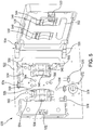
- the dialysis system 100, 200 includes a top unit 101, 201 that is detachably affixed to a base 102, 202.
- Base unit 102, 202 contains a reservoir 122, 222 for fluid storage, measurement, and monitoring.
- Top unit 101, 201 also referred to as the main unit or controller unit, includes a graphical user interface 114, 214, a pumping unit, and a door 110, 210 having a power lock.
- a clasp 105 used to detachably affix a dialyzer 103, 313.
- a sorbent cartridge locking base 104, 204, 318 that is used to detachably affix a sorbent cartridge 107, 317.
- Clasp 105, hemofilter 103, 315, sorbent cartridge locking base 104, 204, 318 and sorbent cartridge 107, 317 can be positioned on the same side of top unit 101, as shown in FIG. 3 , or on different sides or at different positions.
- base unit 102, 202, 302 can have a sufficiently larger top surface area relative to the top unit such that shelves can be formed on either side of the top unit to hold the sorbent cartridge, to hold an infusate jar, to capture any spillage, and/or to channel any leaks into a leak detector.
- a door 319 is shown in an open position to reveal a manifold 320 mounted to the top unit 301.
- a handle 311 can be provided on top unit 301.
- top unit 301 can be positioned on one side of base unit 302, as opposed to being centrally positioned on top of base unit 302. Further details of suitable dialysis machines and components thereof, which can be used to carry out the methods of the present invention and form the systems of the present invention, are described, for example, in U.S. Patent Application Publication No. US 2011/0315611 A1 .
- a manifold 410 can be provided that has a capital I-shaped body 412.
- Manifold body 412 can include a first transom 414 and a second transom 416 that are joined together by a central member or trunk 418. Both transoms can have first and second arms located on either side of trunk, for example, a first arm 420 can be on a left side of transom 414 and a second arm 422 can be on the right side of transom 414.
- third and fourth arms 424, 426 can be on respective sides of second transom 416.
- First transom 414 can have first, second, and third edges 428, 430, and 432, respectively.
- First edge 428 spans first transom 414, and second edge 430 and third edge 432 are along first arm 420 and second arm 422, respectively.
- Second transom 416 can have fourth, fifth, and sixth edges, 434, 436, and 438, respectively.
- Fourth edge 434 spans second transom 416, and fifth edge 436 and sixth edge 438 are along third arm 424 and fourth arm 426, respectively.
- Various conduits can be located in manifold body 412 and can be in fluid communication with valves, pressure sensor chambers, and other elements within manifold body 412 as well as being in fluid communication with one or more manifold ports on manifold body 412.
- the manifold ports can include intra-manifold ports and external ports.
- the intra-manifold ports can be joined by one or more pumping tube, and the external ports can fluidly connect the manifold to other portions of the dialysis machine and to the patient, via tubes.
- the tubes can be flexible.
- a flexible membrane or sheet can cover part of one or more sides of the manifold and can form part of the manifold body.
- the external ports can be lettered from “A” to "M” (omitting "I").
- the intra-manifold ports can be referred to by ordinal numbers, for example, 440, 442, 444, 446, 448, 450, 452, and 454.
- External ports A and B are shown along first edge 428 of first transom 414 and external ports C through M are arrayed along fourth edge 434 of second transom 416.
- First and second intra-manifold ports 440, 442 are arrayed along second edge 430 of first arm 420.
- Third and fourth intra-manifold ports 444, 446 are arrayed along third edge 432 of second arm 422.
- a first pumping tube 456 joins first and fifth intra-manifold ports 440, 448, respectively.
- a second pumping tube 458 joins second and sixth intra-manifold ports, 442, 450, respectively.
- a third pumping tube 460 joins third and seventh intra-manifold ports, 444, 452, fourth pumping tube 462 joins the fourth and eighth intra-manifold ports 446, 454, respectively.
- a first conduit 464 can extend from external port A to first intra-manifold port 440 and can contain a first pressure sensor chamber 466.
- a second conduit 468 can extend from fifth intra-manifold port 448 to external port C.
- a third conduit 470 can branch off of second conduit 468 and extend to external port D.
- a fourth conduit 472 can extend between external port F and external port G, and can contain a second pressure sensor chamber 474.
- a fifth conduit 476 can extend from external port J to a first multivalve 478.
- a sixth conduit 480 can extend from first multivalve 478 to the fourth intra-manifold port 446, and can contain a third pressure sensor chamber 482.
- a seventh conduit 484 can extend from eighth intra-manifold port 454 to external port M, and can include a fourth pressure sensor chamber 486.
- An eighth conduit 488 can extend from external port E to sixth intra-manifold port 450.
- a ninth conduit 490 can extend from second intra-manifold port 442 to a second multivalve 492, and can include a fifth pressure sensor chamber 494.
- a tenth conduit 496 can extend from second multivalve 492 to external port H.
- An eleventh conduit 498 can extend from external port B to a third multivalve 500.
- a twelfth conduit 502 can connect third multivalve 500 to first multivalve 478, and a thirteenth conduit 504 can connect second and third multivalves 492, 500 respectively.
- a fourteenth conduit 506 can extend from external port L to seventh intra-manifold port 452.
- a fifteenth conduit 508 can extend from third intra-manifold port 444 to external port K. While certain conduits are described as containing a pressure sensor chamber, any conduit can contain any number of pressure sensor chambers.
- Each pressure sensor chamber can be independently covered by the flexible sheet and be aligned with a pressure sensor on a dialysis machine housing to allow for pressure measurements of a fluid with a given conduit.
- the multivalves can also be covered by the flexible sheet and can be aligned with actuators on a dialysis machine housing, the actuators being configured to control the multivalves and flow through the multivalves.
- FIG. 5 is a partial view of a dialysis machine 520 in accordance with the present invention.
- Dialysis machine 520 has a machine housing 522 to which first and second hinges 524, 526, respectively, are mounted.
- a door 528 is, in turn, mounted to these hinges.
- Door 528 is shown in an open position in FIG. 5 , but can be closed and secured with a door lock that includes a door lock insert 530 attached to door 528, and a door lock receptacle 532 disposed in machine housing 522.
- a manifold receptacle 534 is mounted on machine housing 522 and is configured to receive a manifold, for example, manifold 410 shown in FIG. 4 .
- First, second, third, and fourth peristaltic pumps 536, 538, 540, and 542, respectively, are inset in machine housing 522 and positioned to engage first, second, third, and fourth pump tubes or pump headers, for example, pump tubes 456, 458, 460, and 462, shown in FIG. 4 , respectively.
- First, second, third, and fourth pump shoes 544, 546, 548, and 550, respectively, are mounted on the inside of door 528 and are configured to press first, second, third, and fourth pump tubes of a manifold against first, second, third, and fourth peristaltic pumps 536, 538, 540, and 542, respectively.
- a platen 552 is also mounted on the inside of door 528 and is configured to press a manifold, for example, manifold 410, shown in FIG. 4 , into manifold receptacle 534.
- First, second, third, fourth, and fifth pressure sensors 554, 556, 558, 560, and 562, respectively, are positioned on machine housing 522 within manifold receptacle 534 to engage first, second, third, fourth, and fifth pressure sensor chambers 466, 474, 482, 486, and 494, shown in FIG. 4 , respectively.
- a first set of valve actuators 564 is positioned in machine housing 522 within manifold receptacle 534, to engage first multivalve 478 shown in FIG. 4 .
- a second set of valve actuators 566 is positioned in machine housing 522 within manifold receptacle 534 to engage second multivalve 492 shown in FIG. 4 .
- a third set of valve actuators 568 is positioned in machine housing 522 within manifold receptacle 534 to engage third multivalve 500 shown in FIG. 4 .
- First and second air detectors 570, 572 are included in machine housing 522.
- a blood leak detector 574, an occlusion detector 576, and a bloodline clamp 578, are also included in machine housing 522.
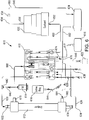
- FIG. 6 shows a schematic diagram of a hemodialysis system 610 that can utilize a suitable manifold, for example, manifold 410, the details of which are shown in FIG. 4 .
- External tubes preferably flexible, are used to connect the manifold via the external ports to other components of the dialysis system, such as a dialyzer 612, an anticoagulant source 614, a saline source 616, an electrolyte source 618, a sorbent cartridge 620, a dialysate source 622, and a dialysate reservoir 624.
- the manifold, external tubes, and other dialysis system components can form one or more circuits, for example, an extracorporeal blood circuit and a dialysate circuit.
- a given tube can be made of one or more shorter tubes joined together by one or more connectors.
- an extracorporeal blood circuit 626 is provided in the hemodialysis system shown.
- a first external tube 628 can extend from the patient, for example, an artery of the patient, to external port C.
- a second external tube 630 can extend from external port A to a first dialyzer port 632.
- a third external tube 634 can extend from a second dialyzer port 636 to external port G.
- a fourth external tube 638 can extend from external port F back to the patient, for example, to a vein of the patient.
- a fifth external tube 640 can connect anti-coagulant source 614 to the extracorporeal blood circuit 626, for example, at a first branch point 642 in second external tube 630.
- a sixth external tube 644 can connect saline source 616 to external port D.
- blood can flow in extracorporeal blood circuit 626 in the following manner.
- the flow can be powered and controlled by first peristaltic pump 536, shown in FIG. 5 , operatively associated with first pump tube 456, shown in FIG. 4 .
- Blood can flow from the patient, for example, out of an artery, through first external tube 628, through second conduit 468, first pump tube 456, through first conduit 464, through second external tube 630, through dialyzer 612, through third external tube 634, through fourth conduit 472, through fourth external tube 638, and back to the patient, for example, into a vein of the patient.
- Anticoagulant can be supplied through fifth external tube 640 into extracorporeal blood circuit 626.
- a priming sequence can be used in extracorporeal blood circuit 626 by flowing saline from saline source 616 through external tube 644 and third conduit 470 into extracorporeal blood circuit 626, for example, at a location along second conduit 468.
- Flow in extracorporeal blood circuit 626 is also shown in FIG. 7 , which further depicts a pinch valve 573.
- a dialysate circuit 646 can also form part of hemodialysis system 610.
- a seventh external tube 648 can extend from a dialysate or water source 622 to external port J.
- An eighth external tube 650 can extend from external port M to a first sorbent cartridge port 652.
- a ninth external tube 654 can extend from a second sorbent cartridge port 656 to an ammonia sensor 658.
- a tenth external tube 660 can extend from ammonia sensor 658 to dialysate reservoir 624.
- An eleventh external tube 662 can extend from dialysate reservoir 624 to external port E.
- a twelfth external tube 664 can extend from external port H to a third dialyzer port 665.
- a thirteenth external tube 668 can extend from a fourth dialyzer port 670 to external port B.
- a fourteenth external tube 672 can extend from electrolyte source 618 to external valve port L.
- a fifteenth external tube 674 can extend from external port K to a second branch point 676 in eleventh external tube 662.
- dialysate can flow through dialysate circuit 646, which can be powered by second and fourth peristaltic pumps 538, 542, respectively, shown in FIG. 5 , which are in operative association with second and fourth pump tubes 458, 462, respectively, shown in FIG. 4 .
- Third peristaltic pump 540 can be in operative association with third pump tube 460 to allow a flow of electrolytes to enter dialysate circuit 646.
- Dialysate, or water can flow from dialysate source 622 through seventh external tube 648, fifth conduit 476, sixth conduit 480, fourth pump tube 462, seventh conduit 484, eighth external tube 650, sorbent cartridge 620, ninth external tube 654, ammonia sensor 658, tenth external tube 660, dialysate reservoir 624, eleventh external tube 662, eighth conduit 488, second pump tube 458, ninth conduit 490, tenth conduit 496, twelfth external tube 664, dialyzer 612, thirteenth external tube 668, eleventh conduit 498, twelfth conduit 502, and back to sixth conduit 480, to complete dialysate circuit 646.
- Electrolytes can flow through fourteenth external tube 672, fourteenth conduit 506, pump tube 460, fifteen conduit 508, and into dialysis circuit 646, for example, at second branch point 676 along eleventh external tube 662.
- Dialysate circuit 646 is also shown in FIG. 7 , which further depicts a scale 623 and a heater/thermistor assembly 625, as well as a level detector 619 for measuring the amount of electrolyte solution in electrolyte source 618.
- FIG. 7 the same reference numbers used in FIGS. 4 - 6 depict the same features.
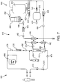
- FIG. 8 is a schematic circuit diagram of a peritoneal dialysis system 810 in accordance with the present invention.
- FIG. 9 is a schematic flow diagram of peritoneal dialysis system 810.
- Various components referred to in this description of peritoneal dialysis system 810 are shown in FIGS. 4-6 and discussed above, and the same reference numbers depict the same features.
- Dialysate can be pumped using first peristaltic pump 536 into a dialysate circuit 812 from an appropriate peritoneal dialysate source, for example, a prepared, sterile bag of dialysate 813, through a first external tube 814, external port C, second conduit 468, fifth intra-manifold port 448, first pump tube 456, first intra-manifold port 440, first conduit 464, external port A, a second external tube 816, and into dialysate reservoir 624.
- an appropriate peritoneal dialysate source for example, a prepared, sterile bag of dialysate 813
- Dialysate can be heated and weighed in dialysate reservoir 624 and then pumped using second peristaltic pump 538 to the peritoneum of a patient through third external tube 818, external port E, eighth conduit 488, sixth intra-manifold port 450, second pump tube 458, second intra-manifold port 442, ninth conduit 490, second multivalve 492, tenth conduit 496, external port H, and fourth external tube 820.
- dialysate can be pumped back to dialysate circuit 812 using fourth peristaltic pump 542 through fourth external tube 820, external port H, tenth conduit 496, second multivalve 492, thirteenth conduit 504, third multivalve 500, twelfth conduit 502, first multivalve 478, sixth conduit 480, fourth intra-manifold port 446, fourth pump tube 462, eighth intra-manifold port 454, seventh conduit 484, external port M, fifth external tube 822, and into drain bag 824.
- the dialysate can be weighed in drain bag 824 before being pumped out and back to the manifold again using fourth dialysate pump 542, through fifth external tube 822, external port M, seventh conduit 484, eighth intra-manifold port 454, fourth pump tube 462, fourth intra-manifold port 446, sixth conduit 480, first multivalve 478, fifth conduit 476, external port J, sixth external tube 826, and into a waste receptacle 828.
- a "last bag” 831 for example, holding a dialysate having an alternative formulation to that used initially, can be pumped into dialysate circuit 812 using second dialysate pump 538, through a seventh external tube 830, external port B, eleventh conduit 498, third multivalve 500, thirteenth conduit 504, second multivalve 492, ninth conduit 490, second intra-manifold port 442, second pump tube 458, sixth intra-manifold port 450, eighth conduit 488, external port E, third external tube 818 and into dialysate reservoir 624.
- the dialysate can then be heated and weighed before being pumped to the peritoneal cavity, pumped back, and then drained in the manner described above for the original dialysate cycled through dialysate circuit 812.
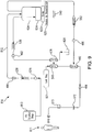
- FIG. 10 is a schematic circuit diagram of a peritoneal dialysis system 1010 in accordance with the present invention.
- FIG. 11 is a schematic flow diagram of peritoneal dialysis system 1010.
- Various components referred to in this description of peritoneal dialysis system 1010 are shown in FIGS. 4 - 6 and discussed above, and the same reference numbers depict the same features.
- Peritoneal dialysis system 1010 can be understood as a modification of hemodialysis system 610 shown in FIGS. 6 and 7 , and uses manifold 410 shown in FIG. 4 .
- the "X's" shown in FIGS. 10 and 11 show fluid paths from hemodialysis system 610, which are not utilized in system 1010.
- dialyzer 612 serves as a filter between the patient and dialysis circuit 1012.
- Dialysate for example, prepared dialysate from an external source, can be pumped using fourth peristaltic pump 542 through seventh external tube 648, external port J, fifth conduit 476, first multivalve 478, sixth conduit 480, fourth intra-manifold port 446, fourth pump tube 462, eighth intra-manifold port 454,seventh conduit 484, eighth external tube 650, sorbent cartridge 620, ninth external tube 654, ammonia sensor 658, tenth external tube 660, and dialysate reservoir 624, then pumped using second peristaltic pump 538 through eleventh external tube 662, external port E, eighth conduit 488, sixth intra-manifold port 450, second pumping tube 458, second intra-manifold port 442, ninth conduit 490, and second multivalve 492, where the flow
- First flow path 1014 passes through eleventh conduit 498, external port B, thirteenth external tube 668, and into dialyzer 612 through fourth dialyzer port 670.
- the second flow path passes through tenth conduit 496, external port H, twelfth external tube 664, and into dialyzer 612 through third dialyzer port 665.
- First and second flow paths 1014, 1016 converge in dialyzer 612 and pass through the dialyzer, for example, semi-permeable membrane therein.
- the dialysate then passes through second dialyzer port 636, through third external tube 634, external port G, fourth conduit 472, external port F, and to the peritoneum of patient 611. After an appropriate dwell time, the dialysate is returned from patient 611 to dialysate circuit 1012.
- first and second flow paths 1014, 1016 converge at third multivalve 500.
- the dialysate then flows through twelfth conduit 502, and back to sixth conduit 480 to complete dialysate circuit 1012.
- Electrolytes can be added to dialysate circuit 1012 from electrolyte source 618 using third peristaltic pump 540.
- one of first and second flow paths 1014, 1016, respectively can be used when pumping dialysate toward the peritoneum and the other of the two flow paths can be used when pumping dialysate from the peritoneum.
- the same flow path can be used in both directions.
- dialysate flow can be split in one direction, and not split in the other direction.
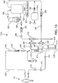
- FIG. 12 is a schematic circuit view of a peritoneal dialysis system 1210 in accordance with the present invention.
- FIG. 13 is a schematic flow diagram of peritoneal dialysis system 1210.
- Various components referred to in this description of peritoneal dialysis system 1210 are shown in FIGS. 4 - 6 and discussed above, and the same reference numbers depict the same features.
- Peritoneal dialysis system 1210 can be understood as a modification of hemodialysis system 610 shown in FIGS. 6 and 7 , and uses manifold 410 shown in FIG. 4 .
- extracorporeal blood circuit 626 shown in FIGS. 6 and 7 becomes peritoneum circuit 1226.
- an anti-coagulant source is not needed as blood is not being circulated. Instead, a glucose source 1214, or other osmotic agent source, can take the place of anti-coagulant source 614. While the flow paths of hemodialysis system 610 can remain unchanged in peritoneal dialysis system 1210, various modifications can be made, for example, for sterility and anti-contamination purposes.
- one or more bacterial filters can be placed in twelfth external tube 664.
- a second dialyzer 1212 can be used as such a filter.
- Twelfth external tube 664 can be replaced with a first branched tube 1216 and a second branched tube 1218.
- First branched tube 1216 can fluidly connect manifold 410 at external port H to second dialyzer 1212.
- Second branched tube 1218 can fluidly connect second dialyzer 1212 to third dialyzer port 665.
- Dialysate for peritoneum circuit 1226 can be pumped in using first dialysate pump 536 from a prepared dialysate source through external port D and third conduit 470.
- dialysate for peritoneum circuit 1226 can be prepared by pumping in dialysate and/or water from dialysate source 622 ( FIG. 6 ) using fourth peristaltic pump 542 through seventh external tube 648, external port J, fifth conduit 476, sixth conduit 480, fourth pump tube 462, seventh conduit 484, eighth external tube 650, sorbent cartridge 620, ninth external tube 654, ammonia sensor 658, tenth external tube 660, and dialysate reservoir 624.
- dialysate can be pumped by second peristaltic pump 538 through eleventh external tube 662, eighth conduit 488, second pumping tube 458, ninth conduit 490, tenth conduit 496, and into dialyzer 612 through third and/or fourth dialyzer ports, 665, 670, respectively, wherein the dialysate passes through the membrane therein and into peritoneum circuit 1226.
- Dialysate can be similarly prepared for and retained in dialysate circuit 646.
- Continuous flow peritoneal dialysis can then be performed with a first dialysate flowing through peritoneum circuit 1226 to and from patient 611, and a second dialysate circulating through dialysate circuit 646 serving to dialyze the first dialysate across the membrane of dialyzer 612.
- the first dialysate can be periodically weighed by draining off the second dialysate from dialysate circuit 646 and flowing the first dialysate across the membrane of dialyzer 612 from peritoneum circuit 1226 into dialysate circuit 646.
- This transfer can be performed to determine ultrafiltration and can be achieved by stopping first and second peristaltic pumps 536, 538, respectively, while continuing to pump with fourth dialysate pump 542 to deliver the first dialysate to dialysate reservoir 624 to be weighed using scale 623.
- a difference between the initial weight of the first dialysate infused into peritoneum circuit 1226, and the resulting first dialysate, can be used as a determination of ultrafiltration.
- the first dialysate can then be pumped back into peritoneum circuit 1226, and dialysate circuit 646 can be refilled with dialysate to provide a second dialysate again.
- the dialysis process can then be restarted.
Landscapes
- Health & Medical Sciences (AREA)
- Urology & Nephrology (AREA)
- Heart & Thoracic Surgery (AREA)
- Emergency Medicine (AREA)
- Anesthesiology (AREA)
- Engineering & Computer Science (AREA)
- Vascular Medicine (AREA)
- Biomedical Technology (AREA)
- Hematology (AREA)
- Life Sciences & Earth Sciences (AREA)
- Animal Behavior & Ethology (AREA)
- General Health & Medical Sciences (AREA)
- Public Health (AREA)
- Veterinary Medicine (AREA)
- External Artificial Organs (AREA)
Applications Claiming Priority (2)
| Application Number | Priority Date | Filing Date | Title |
|---|---|---|---|
| US13/828,636 US9433720B2 (en) | 2013-03-14 | 2013-03-14 | Universal portable artificial kidney for hemodialysis and peritoneal dialysis |
| PCT/US2014/025450 WO2014159918A2 (en) | 2013-03-14 | 2014-03-13 | Universal portable artificial kidney for hemodialysis and peritoneal dialysis |
Publications (2)
| Publication Number | Publication Date |
|---|---|
| EP2968725A2 EP2968725A2 (en) | 2016-01-20 |
| EP2968725B1 true EP2968725B1 (en) | 2021-11-03 |
Family
ID=50819939
Family Applications (1)
| Application Number | Title | Priority Date | Filing Date |
|---|---|---|---|
| EP14726448.5A Active EP2968725B1 (en) | 2013-03-14 | 2014-03-13 | Universal portable artificial kidney for hemodialysis and peritoneal dialysis |
Country Status (5)
| Country | Link |
|---|---|
| US (3) | US9433720B2 (zh) |
| EP (1) | EP2968725B1 (zh) |
| CN (2) | CN107281569B (zh) |
| HK (1) | HK1215402A1 (zh) |
| WO (1) | WO2014159918A2 (zh) |
Families Citing this family (18)
| Publication number | Priority date | Publication date | Assignee | Title |
|---|---|---|---|---|
| US20140263062A1 (en) | 2013-03-14 | 2014-09-18 | Fresenius Medical Care Holdings, Inc. | Universal portable machine for online hemodiafiltration using regenerated dialysate |
| US9433720B2 (en) | 2013-03-14 | 2016-09-06 | Fresenius Medical Care Holdings, Inc. | Universal portable artificial kidney for hemodialysis and peritoneal dialysis |
| DE102015010468A1 (de) * | 2015-08-11 | 2017-02-16 | Fresenius Medical Care Deutschland Gmbh | Peritonealdialysegerät |
| CN105457116A (zh) * | 2015-12-18 | 2016-04-06 | 昆山韦睿医疗科技有限公司 | 一种一体化腹膜透析设备 |
| US10561778B2 (en) * | 2017-03-02 | 2020-02-18 | Fresenius Medical Care Holdings, Inc. | Split reservoir bags and method of using split reservoir bags to improve the heating and generation of dialysate |
| US11389575B2 (en) * | 2017-07-14 | 2022-07-19 | Fresenius Medical Care Holdings, Inc. | Prescription compatibility checking for a medical device |
| US20190151527A1 (en) * | 2017-11-22 | 2019-05-23 | Medtronic, Inc. | Dialysis system of integrated manifolds |
| CN111565772A (zh) * | 2017-12-06 | 2020-08-21 | 费森尤斯医疗护理德国有限责任公司 | 可移动透析椅 |
| US11278654B2 (en) | 2017-12-07 | 2022-03-22 | Medtronic, Inc. | Pneumatic manifold for a dialysis system |
| US11033667B2 (en) | 2018-02-02 | 2021-06-15 | Medtronic, Inc. | Sorbent manifold for a dialysis system |
| US11110215B2 (en) | 2018-02-23 | 2021-09-07 | Medtronic, Inc. | Degasser and vent manifolds for dialysis |
| US10514363B2 (en) | 2018-02-23 | 2019-12-24 | The Boeing Company | Laser ultrasound scanning for visualizing damage or irregularities |
| CN110269867B (zh) * | 2018-03-14 | 2022-06-21 | 必康生技(香港)有限公司 | 用于生物流体净化的组合物 |
| WO2020198483A1 (en) * | 2019-03-26 | 2020-10-01 | Chf Solutions, Inc. | Neonatal and pediatric blood filtration system |
| US11548161B2 (en) | 2020-05-14 | 2023-01-10 | The Boeing Company | Methods of performing a plurality of operations within a region of a part utilizing an end effector of a robot and robots that perform the methods |
| USD1008463S1 (en) * | 2020-10-06 | 2023-12-19 | Byonyks Medical Devices, Inc. | Multiple pressure sensing system for peritoneal dialysis |
| US11639914B2 (en) | 2020-12-16 | 2023-05-02 | The Boeing Company | Non-destructive test systems with infrared thermography assemblies and ultrasonic test assemblies, and associated methods |
| US11986584B1 (en) | 2023-02-20 | 2024-05-21 | Nuwellis, Inc. | Extracorporeal blood filtering machine and methods |
Family Cites Families (243)
| Publication number | Priority date | Publication date | Assignee | Title |
|---|---|---|---|---|
| US2328381A (en) | 1940-08-28 | 1943-08-31 | Samuel R Jaffe | Pipe joint |
| US3707967A (en) | 1970-10-01 | 1973-01-02 | Tecna Corp | Steady flow regenerative peritoneal dialysis system and method |
| DE2239254C2 (de) | 1970-12-30 | 1983-08-04 | Organon Teknika Corp., Oklahoma City, Okla. | "Säule zur Regenerierung einer zirkulierenden Dialysatlösung und Verwendung dieser Säule". |
| US4370983A (en) | 1971-01-20 | 1983-02-01 | Lichtenstein Eric Stefan | Computer-control medical care system |
| DE2542438C3 (de) | 1975-09-24 | 1981-01-22 | Dr. Eduard Fresenius Chemisch-Pharmazeutische Industrie Kg Apparatebau Kg, 6380 Bad Homburg | Dialysator |
| US4071444A (en) | 1976-10-12 | 1978-01-31 | Purdue Research Foundation | Portable chemical reactor for use as an artificial kidney |
| NL7703937A (nl) | 1977-04-12 | 1978-10-16 | Organon Teknika Bv | Inrichting voorzien van een sorbent voor het zuiveren van bloed; een voor orale toepassing geschikt sorbent en een werkwijze voor vervaar- diging van het sorbent. |
| DE2721444A1 (de) | 1977-05-12 | 1978-11-16 | Fresenius Chem Pharm Ind | Hohlfaserdialysator |
| US4190047A (en) | 1977-08-26 | 1980-02-26 | University Of Utah | Method and apparatus for peritoneal dialysis |
| US4581141A (en) | 1978-02-27 | 1986-04-08 | Purdue Research Foundation | Dialysis material and method for removing uremic substances |
| DE2847945C2 (de) | 1978-11-04 | 1984-01-12 | Fresenius AG, 6380 Bad Homburg | Künstliche Niere und Verfahren zu ihrer Herstellung |
| US4247393A (en) | 1979-01-11 | 1981-01-27 | Wallace Richard A | Hemodialysis assist device |
| US4311587A (en) | 1979-12-10 | 1982-01-19 | Japan Foundation For Artificial Organs | Filter arrangement denying bacteria entry to peritoneum |
| US4403984A (en) | 1979-12-28 | 1983-09-13 | Biotek, Inc. | System for demand-based adminstration of insulin |
| US4368737A (en) | 1980-07-07 | 1983-01-18 | Purdue Research Foundation | Implantable catheter |
| US4348283A (en) | 1980-11-05 | 1982-09-07 | Purdue Research Foundation | Reciprocating dialyzer having spacers |
| US4347136A (en) | 1981-02-18 | 1982-08-31 | Neil Friesen | Bacteria static filter assembly |
| US4402694A (en) | 1981-07-16 | 1983-09-06 | Biotek, Inc. | Body cavity access device containing a hormone source |
| US4387777A (en) | 1981-10-26 | 1983-06-14 | Willo Partners | Calorie counting method and apparatus |
| US4469593A (en) | 1982-03-10 | 1984-09-04 | Kabushiki Kaisha Toyota Chuo Kenkyusho | Blood purification apparatus |
| US4413988A (en) | 1982-04-28 | 1983-11-08 | Handt Alan E | Short-tubing set gravity powered peritoneal cycler |
| US4498902A (en) | 1982-11-13 | 1985-02-12 | Purdue Research Foundation | Catheter guide |
| US4568366A (en) | 1983-08-30 | 1986-02-04 | Baxter Laboratories, Inc. | In-line filter |
| US4559039A (en) | 1983-12-05 | 1985-12-17 | Purdue Research Foundation | Permanently placed transcutaneous access device to blood vessels |
| US4661246A (en) | 1984-10-01 | 1987-04-28 | Ash Medical Systems, Inc. | Dialysis instrument with dialysate side pump for moving body fluids |
| US5198335A (en) | 1985-06-04 | 1993-03-30 | Fuji Photo Film Co., Ltd. | Integral multilayer analytical element for analysis of ammonia-forming substrate |
| US4740755A (en) | 1986-05-30 | 1988-04-26 | Cobe Laboratories, Inc. | Remote conductivity sensor having transformer coupling in fluid flow path |
| US4854322A (en) | 1987-02-25 | 1989-08-08 | Ash Medical Systems, Inc. | Capillary filtration and collection device for long-term monitoring of blood constituents |
| US4777953A (en) | 1987-02-25 | 1988-10-18 | Ash Medical Systems, Inc. | Capillary filtration and collection method for long-term monitoring of blood constituents |
| US5002054A (en) | 1987-02-25 | 1991-03-26 | Ash Medical Systems, Inc. | Interstitial filtration and collection device and method for long-term monitoring of physiological constituents of the body |
| US5032261A (en) | 1988-05-24 | 1991-07-16 | Dufresne-Henry, Inc. | Compact biofilter for drinking water treatment |
| US5230341A (en) | 1988-08-13 | 1993-07-27 | Fresenius Ag | Measuring the change of intravascular blood volume during blood filtration |
| US4943279A (en) | 1988-09-30 | 1990-07-24 | C. R. Bard, Inc. | Medical pump with infusion controlled by a detachable coded label |
| DE3837498A1 (de) | 1988-11-04 | 1990-05-17 | Fresenius Ag | Verfahren und vorrichtung zur ultrafiltration bei der haemodialyse |
| US4914819A (en) | 1989-05-17 | 1990-04-10 | Ash Stephen R | Eating utensil for indicating when food may be eaten therewith and a method for using the utensil |
| DE3917251A1 (de) | 1989-05-26 | 1990-11-29 | Fresenius Ag | Natriumbicarbonat enthaltendes konzentrat sowie verfahren zur herstellung einer dialysierfluessigkeit |
| US5114580A (en) | 1989-06-20 | 1992-05-19 | The Board Of Regents Of The University Of Washington | Combined hemofiltration and hemodialysis system |
| US4995268A (en) | 1989-09-01 | 1991-02-26 | Ash Medical System, Incorporated | Method and apparatus for determining a rate of flow of blood for an extracorporeal blood therapy instrument |
| DE3936785C1 (zh) | 1989-11-04 | 1991-03-28 | Fresenius Ag, 6380 Bad Homburg, De | |
| DE3938662A1 (de) | 1989-11-21 | 1991-07-18 | Fresenius Ag | Verfahren zur in-vivo-bestimmung von parametern der haemodialyse |
| ATE145142T1 (de) | 1991-02-08 | 1996-11-15 | Alan M Peabody | System zur kontinuierlichen peritonaldialyse |
| US6471872B2 (en) | 1991-10-11 | 2002-10-29 | Children's Hospital Medical Center | Hemofiltration system and method based on monitored patient parameters |
| DE4138140C2 (de) | 1991-11-20 | 1993-12-23 | Fresenius Ag | Vorrichtung zur Desinfektion von Hämodialysegeräten mit einem pulverförmigen Konzentrat |
| DE4139165C2 (de) | 1991-11-28 | 1994-12-08 | Fresenius Ag | Einrichtung zur Herstellung einer medizinischen Flüssigkeit |
| US5277820A (en) | 1992-02-06 | 1994-01-11 | Hemocleanse, Inc. | Device and method for extracorporeal blood treatment |
| US5919369A (en) | 1992-02-06 | 1999-07-06 | Hemocleanse, Inc. | Hemofiltration and plasmafiltration devices and methods |
| US5536412A (en) | 1992-02-06 | 1996-07-16 | Hemocleanse, Inc. | Hemofiltration and plasmafiltration devices and methods |
| NO306806B1 (no) | 1992-06-26 | 1999-12-27 | Fresenius Ag | Pose for opptak av konsentrat |
| US5476444A (en) | 1992-09-04 | 1995-12-19 | Idt, Inc. | Specialized perfusion protocol for whole-body hyperthermia |
| US6156007A (en) | 1992-09-04 | 2000-12-05 | Hemotherm, Inc. | Apparatus for whole-body hyperthermia |
| DE4230513C1 (de) | 1992-09-11 | 1994-03-31 | Fresenius Ag | Vorrichtung zur Entfernung von Aluminiumionen aus Blut und Lösung zur Verwendung in der Vorrichtung |
| DE4239937C2 (de) | 1992-11-27 | 1995-08-24 | Fresenius Ag | Verfahren zur Feststellung der Funktionsfähigkeit einer Teileinrichtung eines Hämodialysegerätes und Vorrichtung zur Durchführung dieses Verfahrens |
| US5322519A (en) | 1993-02-17 | 1994-06-21 | Ash Medical Systems, Inc. | Foldable catheter for peritoneal dialysis |
| US5624551A (en) | 1993-04-28 | 1997-04-29 | Fresenius Ag | Hydraulic safety circuit for a hemodialysis apparatus |
| US5385005A (en) | 1993-07-12 | 1995-01-31 | Ash; Stephen C. | Lawn trimmer/edge attachment |
| US5308315A (en) | 1993-07-27 | 1994-05-03 | Raja N. Khuri | Method for determining the adequacy of dialysis |
| US5445630A (en) | 1993-07-28 | 1995-08-29 | Richmond; Frank M. | Spike with luer fitting |
| USD370531S (en) | 1993-10-04 | 1996-06-04 | Janin Group, Inc. | Peritoneal dialysis catheter implanter |
| US5460493A (en) | 1993-11-17 | 1995-10-24 | Baxter International Inc. | Organizer frame for holding an array of flexible tubing in alignment with one or more peristaltic pump rotors |
| USD355816S (en) | 1993-11-17 | 1995-02-28 | Ash Stephen C | Trimmer attachment |
| US5577891A (en) | 1993-11-30 | 1996-11-26 | Instech Laboratories, Inc. | Low power portable resuscitation pump |
| SE502222C2 (sv) | 1994-01-17 | 1995-09-18 | Althin Medical Ab | Sätt vid dialys |
| SE502020C2 (sv) | 1994-02-03 | 1995-07-17 | Gambro Ab | Apparat för peritonealdialys |
| DE4419593A1 (de) | 1994-06-03 | 1995-12-07 | Fresenius Ag | Vorrichtung zum Messen des Drucks eines Mediums |
| DE4422100C1 (de) | 1994-06-24 | 1995-12-14 | Fresenius Ag | Flexible medizinische Verpackungseinheit für die Hämodialyse zur Herstellung eines Dialysierflüssigkeit-Konzentrats sowie Vorrichtung hierfür |
| DE4440556A1 (de) | 1994-11-12 | 1996-05-15 | Polaschegg Hans Dietrich Dr | Einrichtung und Verfahren zur Bestimmung der Menge an entfernten Urämietoxinen bei einer Hämodialysebehandlung |
| DE4443714C2 (de) | 1994-12-09 | 1996-10-17 | Fresenius Ag | Vorrichtung zum Steuern eines Fluidverlaufes |
| US5782796A (en) | 1995-02-10 | 1998-07-21 | Baxter International Inc. | Foldable dialysis unit with integral pump and a method for performing solution exchange |
| US5795317A (en) | 1995-06-07 | 1998-08-18 | Cobe Laboratories, Inc. | Extracorporeal blood processing methods and apparatus |
| US5609770A (en) | 1995-06-07 | 1997-03-11 | Cobe Laboratories, Inc. | Graphical operator machine interface and method for information entry and selection in a dialysis machine |
| US5698083A (en) | 1995-08-18 | 1997-12-16 | Regents Of The University Of California | Chemiresistor urea sensor |
| US5944684A (en) | 1995-08-31 | 1999-08-31 | The Regents Of The University Of California | Wearable peritoneum-based system for continuous renal function replacement and other biomedical applications |
| US5711883A (en) | 1995-09-27 | 1998-01-27 | Fresenius Usa, Inc. | Method for testing dialyzer integrity prior to use |
| US5868933A (en) | 1995-12-15 | 1999-02-09 | Patrick; Gilbert | Antimicrobial filter cartridge |
| DE19607162C2 (de) | 1996-02-26 | 1998-01-15 | Fresenius Ag | Verwendung eines Dialysators mit zwei Modulen zur Durchführung eines Verfahrens zum Filtrieren und sofortigen Verwenden von Substituatflüssigkeit in einer Hämodialfiltrationsvorrichtung |
| US5906978A (en) | 1996-08-14 | 1999-05-25 | Hemocleanse, Inc. | Method for iron delivery to a patient by transfer from dialysate |
| WO1998017333A2 (en) | 1996-10-22 | 1998-04-30 | Hemocleanse, Inc. | Continuous flow-through peritoneal dialysis (cfpd) method with control of intraperitoneal pressure |
| US5858186A (en) | 1996-12-20 | 1999-01-12 | The Regents Of The University Of California | Urea biosensor for hemodialysis monitoring |
| US6673314B1 (en) | 1997-02-14 | 2004-01-06 | Nxstage Medical, Inc. | Interactive systems and methods for supporting hemofiltration therapies |
| US20010016699A1 (en) | 1997-02-14 | 2001-08-23 | Jeffrey H. Burbank | Hemofiltration system |
| US6595943B1 (en) | 1997-02-14 | 2003-07-22 | Nxstage Medical, Inc. | Systems and methods for controlling blood flow and waste fluid removal during hemofiltration |
| US6554789B1 (en) | 1997-02-14 | 2003-04-29 | Nxstage Medical, Inc. | Layered fluid circuit assemblies and methods for making them |
| US6579253B1 (en) | 1997-02-14 | 2003-06-17 | Nxstage Medical, Inc. | Fluid processing systems and methods using extracorporeal fluid flow panels oriented within a cartridge |
| US6830553B1 (en) | 1997-02-14 | 2004-12-14 | Nxstage Medical, Inc. | Blood treatment systems and methods that maintain sterile extracorporeal processing conditions |
| US6638477B1 (en) | 1997-02-14 | 2003-10-28 | Nxstage Medical, Inc. | Fluid replacement systems and methods for use in hemofiltration |
| US6638478B1 (en) | 1997-02-14 | 2003-10-28 | Nxstage Medical, Inc. | Synchronized volumetric fluid balancing systems and methods |
| US6979309B2 (en) | 1997-02-14 | 2005-12-27 | Nxstage Medical Inc. | Systems and methods for performing blood processing and/or fluid exchange procedures |
| US6852090B2 (en) | 1997-02-14 | 2005-02-08 | Nxstage Medical, Inc. | Fluid processing systems and methods using extracorporeal fluid flow panels oriented within a cartridge |
| US5947953A (en) | 1997-08-06 | 1999-09-07 | Hemocleanse, Inc. | Splittable multiple catheter assembly and methods of inserting the same |
| US6280406B1 (en) | 1997-09-12 | 2001-08-28 | Gambro, Inc | Extracorporeal blood processing system |
| US6042561A (en) | 1997-10-22 | 2000-03-28 | Ash Medical Systems, Inc. | Non-intravascular infusion access device |
| US5989438A (en) | 1997-12-12 | 1999-11-23 | Baxter International Inc. | Active blood filter and method for active blood filtration |
| ATE283712T1 (de) | 1998-01-23 | 2004-12-15 | Viacirq Inc | Vorrichtung und verfahren zur ganzkörper- hyperthermiebehandlung |
| US7004924B1 (en) | 1998-02-11 | 2006-02-28 | Nxstage Medical, Inc. | Methods, systems, and kits for the extracorporeal processing of blood |
| US6582385B2 (en) | 1998-02-19 | 2003-06-24 | Nstage Medical, Inc. | Hemofiltration system including ultrafiltrate purification and re-infusion system |
| WO1999048598A1 (en) | 1998-03-25 | 1999-09-30 | Watermate Filtering System Inc. | Filter system |
| DE19823836C2 (de) | 1998-05-28 | 2000-05-04 | Fresenius Medical Care De Gmbh | Vorrichtung und Verfahren zum berührungsfreien Messen der Leitfähigkeit einer in einem Strömungskanal befindlichen Flüssigkeit |
| US6217540B1 (en) | 1998-07-10 | 2001-04-17 | Fuji Photo Film Co., Ltd. | Blood filter cartridge |
| US6287516B1 (en) | 1998-07-10 | 2001-09-11 | Immunocept, L.L.C. | Hemofiltration systems, methods, and devices used to treat inflammatory mediator related disease |
| ES2324506T3 (es) | 1998-07-31 | 2009-08-07 | Nephros, Inc. | Dispositivo para hemodiafiltracion eficaz. |
| US6958049B1 (en) | 1998-08-25 | 2005-10-25 | Ash Access Technology, Inc. | Method of enhancing catheter patency using a citrate salt catheter lock solution |
| JP2000107283A (ja) | 1998-10-07 | 2000-04-18 | Nissho Corp | 透析装置および洗浄プライミング方法 |
| US6139739A (en) | 1998-10-08 | 2000-10-31 | Cuno Incorporated | Composite filter element |
| US6254567B1 (en) | 1999-02-26 | 2001-07-03 | Nxstage Medical, Inc. | Flow-through peritoneal dialysis systems and methods with on-line dialysis solution regeneration |
| US6332985B1 (en) | 1999-03-29 | 2001-12-25 | Uop Llc | Process for removing toxins from bodily fluids using zirconium or titanium microporous compositions |
| KR20020029669A (ko) | 1999-07-21 | 2002-04-19 | 데이비드 엠 모이어 | 미생물 필터 및 수중 미생물 제거 방법 |
| US7347849B2 (en) | 2001-05-24 | 2008-03-25 | Nxstage Medical, Inc. | Modular medical treatment replaceable component |
| US6328699B1 (en) | 2000-01-11 | 2001-12-11 | Cedars-Sinai Medical Center | Permanently implantable system and method for detecting, diagnosing and treating congestive heart failure |
| DE10007327A1 (de) | 2000-02-17 | 2001-08-30 | Fresenius Medical Care De Gmbh | Filtervorrichtung, vorzugsweise Hohlfaserdialysator mit gelockten Hohlfasern |
| US6497675B1 (en) | 2000-04-17 | 2002-12-24 | Renal Tech International Llc | Device for extracorporeal treatment of physiological fluids of organism |
| EP1195171B1 (en) * | 2000-10-04 | 2012-08-15 | Terumo Kabushiki Kaisha | Peritoneal dialysis apparatus |
| CN101172171B (zh) | 2000-10-12 | 2012-12-12 | 肾脏治疗公司 | 在体液体外处理中用于体液流动控制的装置和方法 |
| JP4004009B2 (ja) | 2000-10-16 | 2007-11-07 | 富士フイルム株式会社 | アンモニア又はアンモニア生成物質分析用一体型多層分析素子 |
| US6689083B1 (en) | 2000-11-27 | 2004-02-10 | Chf Solutions, Inc. | Controller for ultrafiltration blood circuit which prevents hypotension by monitoring osmotic pressure in blood |
| US7033498B2 (en) | 2000-11-28 | 2006-04-25 | Renal Solutions, Inc. | Cartridges useful in cleaning dialysis solutions |
| US6627164B1 (en) | 2000-11-28 | 2003-09-30 | Renal Solutions, Inc. | Sodium zirconium carbonate and zirconium basic carbonate and methods of making the same |
| DE10114283C2 (de) | 2000-12-22 | 2003-04-24 | Fresenius Medical Care De Gmbh | Verfahren zur Ermittlung der Ionenkonzentration des Blutes eines Patienten bei der citrat-antikoagulierten Hämodialyse und/oder Hämofiltration; Dialysegerät |
| US6706007B2 (en) | 2000-12-29 | 2004-03-16 | Chf Solutions, Inc. | Feedback control of ultrafiltration to prevent hypotension |
| US6579460B1 (en) | 2001-03-13 | 2003-06-17 | Uop Llc | Process and composition for removing toxins from bodily fluids |
| US6572641B2 (en) | 2001-04-09 | 2003-06-03 | Nxstage Medical, Inc. | Devices for warming fluid and methods of use |
| US6773412B2 (en) | 2001-04-13 | 2004-08-10 | Chf Solutions, Inc. | User interface for blood treatment device |
| US6623470B2 (en) | 2001-06-27 | 2003-09-23 | Cleveland Clinic Foundation | Method and apparatus for controlling blood volume and hydration and for indicating resuscitation status of a patient using peripheral venous pressure as a hemodynamic parameter |
| AU2002320187A1 (en) | 2001-06-29 | 2003-03-03 | A.B. Korkor Medical, Inc. | Catheter introducer having an expandable tip |
| US6572576B2 (en) | 2001-07-07 | 2003-06-03 | Nxstage Medical, Inc. | Method and apparatus for leak detection in a fluid line |
| US20030098276A1 (en) | 2001-07-10 | 2003-05-29 | Carlson Robert A. | Filter for removing bacteria and particulates from fluid stream |
| US6702561B2 (en) | 2001-07-12 | 2004-03-09 | Nxstage Medical, Inc. | Devices for potting a filter for blood processing |
| US6649063B2 (en) | 2001-07-12 | 2003-11-18 | Nxstage Medical, Inc. | Method for performing renal replacement therapy including producing sterile replacement fluid in a renal replacement therapy unit |
| US20030010717A1 (en) | 2001-07-13 | 2003-01-16 | Nx Stage Medical, Inc. | Systems and methods for handling air and/or flushing fluids in a fluid circuit |
| US6802821B2 (en) | 2001-10-01 | 2004-10-12 | Fresenius Usa, Inc. | Dialyzer |
| US6743193B2 (en) | 2001-07-17 | 2004-06-01 | Nx Stage Medical, Inc. | Hermetic flow selector valve |
| US20050279696A1 (en) | 2001-08-23 | 2005-12-22 | Bahm Jeannine R | Water filter materials and water filters containing a mixture of microporous and mesoporous carbon particles |
| KR100777951B1 (ko) | 2001-08-23 | 2007-11-28 | 더 프록터 앤드 갬블 캄파니 | 정수 필터 재료, 대응하는 정수 필터 및 그의 사용 방법 |
| US7615152B2 (en) | 2001-08-23 | 2009-11-10 | Pur Water Purification Products, Inc. | Water filter device |
| US6690280B2 (en) | 2001-09-07 | 2004-02-10 | Richard A. Citrenbaum | Apparatus and process for infusion monitoring |
| SE523610C2 (sv) | 2001-10-02 | 2004-05-04 | Gambro Lundia Ab | Metod vid styrning av dialysanordning |
| US7241272B2 (en) | 2001-11-13 | 2007-07-10 | Baxter International Inc. | Method and composition for removing uremic toxins in dialysis processes |
| US6960179B2 (en) | 2001-11-16 | 2005-11-01 | National Quality Care, Inc | Wearable continuous renal replacement therapy device |
| US7309323B2 (en) | 2001-11-16 | 2007-12-18 | National Quality Care, Inc. | Wearable continuous renal replacement therapy device |
| US6878283B2 (en) | 2001-11-28 | 2005-04-12 | Renal Solutions, Inc. | Filter cartridge assemblies and methods for filtering fluids |
| US20030114787A1 (en) | 2001-12-13 | 2003-06-19 | Victor Gura | Wearable peritoneal dialysis system |
| US7040142B2 (en) | 2002-01-04 | 2006-05-09 | Nxstage Medical, Inc. | Method and apparatus for leak detection in blood circuits combining external fluid detection and air infiltration detection |
| US20040167465A1 (en) | 2002-04-30 | 2004-08-26 | Mihai Dan M. | System and method for medical device authentication |
| US7153286B2 (en) * | 2002-05-24 | 2006-12-26 | Baxter International Inc. | Automated dialysis system |
| US7175606B2 (en) | 2002-05-24 | 2007-02-13 | Baxter International Inc. | Disposable medical fluid unit having rigid frame |
| US6960328B2 (en) | 2002-07-15 | 2005-11-01 | Magnesium Elektron, Inc. | Zirconium phosphate and method of making same |
| US7252767B2 (en) | 2002-07-15 | 2007-08-07 | Magnesium Elektron, Inc. | Hydrous zirconium oxide, hydrous hafnium oxide and method of making same |
| WO2004009156A2 (en) | 2002-07-19 | 2004-01-29 | Baxter International Inc. | Systems and methods for peritoneal dialysis |
| EP1523347B1 (en) | 2002-07-19 | 2011-05-18 | Baxter International Inc. | Systems and methods for performing peritoneal dialysis |
| WO2004009158A2 (en) | 2002-07-19 | 2004-01-29 | Baxter International Inc. | Systems and methods for performing peritoneal dialysis |
| US7112273B2 (en) | 2002-09-27 | 2006-09-26 | Nxstage Medical, Inc. | Volumetric fluid balance control for extracorporeal blood treatment |
| US9700663B2 (en) | 2005-01-07 | 2017-07-11 | Nxstage Medical, Inc. | Filtration system for preparation of fluids for medical applications |
| US7276042B2 (en) | 2003-01-23 | 2007-10-02 | National Quality Care, Inc. | Low hydraulic resistance cartridge |
| US7182858B2 (en) | 2003-03-04 | 2007-02-27 | Kinetico Incorporated | Multiple barrier filter apparatus |
| US6872346B2 (en) | 2003-03-20 | 2005-03-29 | Nxstage Medical, Inc. | Method and apparatus for manufacturing filters |
| US7135156B2 (en) | 2003-03-28 | 2006-11-14 | Baxter International Inc. | Method for processing a zirconium oxide composition in crystalline form |
| US7303683B2 (en) | 2003-04-04 | 2007-12-04 | The Clorox Company | Microorganism-removing filter medium having high isoelectric material and low melt index binder |
| US6989101B2 (en) | 2003-04-04 | 2006-01-24 | The Clorox Company | Microorganism-removing filter medium having high isoelectric material and low melt index binder |
| NL1023332C2 (nl) | 2003-05-02 | 2004-11-03 | Norit Proces Technologie Holdi | Membraanfilter met ontluchting en werkwijze voor de vervaardiging daarvan. |
| WO2004105589A2 (en) | 2003-05-28 | 2004-12-09 | Hemocleanse Technologies, Llc | Sorbent reactor for extracorporeal blood treatment systems, peritoneal dialysis systems, and other body fluid treatment systems |
| KR100513102B1 (ko) | 2003-08-28 | 2005-09-07 | 재단법인서울대학교산학협력재단 | 교류 방식 유속 측정 장치 및 이에 사용되는 유속 데이터맵핑 방법 |
| ITMO20030259A1 (it) | 2003-09-25 | 2005-03-26 | Gambro Lundia Ab | User interface per una macchina per il trattamento |
| SE0302698A0 (sv) * | 2003-10-13 | 2005-04-14 | Gambro Lundia Ab | Anordning för genomförande av en peritonealdialysbehandling |
| US8038639B2 (en) | 2004-11-04 | 2011-10-18 | Baxter International Inc. | Medical fluid system with flexible sheeting disposable unit |
| US8029454B2 (en) | 2003-11-05 | 2011-10-04 | Baxter International Inc. | High convection home hemodialysis/hemofiltration and sorbent system |
| US7332096B2 (en) | 2003-12-19 | 2008-02-19 | Fenwal, Inc. | Blood filter assembly having multiple filtration regions |
| ITMO20040191A1 (it) | 2004-07-23 | 2004-10-23 | Gambro Lundia Ab | Macchina e metodo per il trattamento extracorporeo di sangue. |
| US7615028B2 (en) | 2004-12-03 | 2009-11-10 | Chf Solutions Inc. | Extracorporeal blood treatment and system having reversible blood pumps |
| WO2006071532A1 (en) | 2004-12-28 | 2006-07-06 | Renal Solutions, Inc. | Method of synthesizing zirconium phosphate particles |
| US7935074B2 (en) | 2005-02-28 | 2011-05-03 | Fresenius Medical Care Holdings, Inc. | Cassette system for peritoneal dialysis machine |
| US20060195064A1 (en) | 2005-02-28 | 2006-08-31 | Fresenius Medical Care Holdings, Inc. | Portable apparatus for peritoneal dialysis therapy |
| US7405572B2 (en) | 2005-05-02 | 2008-07-29 | Invensys Systems, Inc. | Non-metallic flow-through electrodeless conductivity sensor and leak detector |
| DE102005029709B3 (de) | 2005-06-24 | 2007-01-11 | Fresenius Medical Care Deutschland Gmbh | Dialysegerät |
| US7337674B2 (en) | 2005-06-29 | 2008-03-04 | Nx Stage Medical, Inc. | Pressure detector for fluid circuits |
| RU2317843C2 (ru) | 2005-08-08 | 2008-02-27 | Институт физики прочности и материаловедения Сибирского отделения Российской академии наук (ИФПМ СО РАН) | Фильтрующий материал, способ его получения и способ фильтрования |
| ES2468838T3 (es) | 2005-08-25 | 2014-06-17 | Gambro Lundia Ab | Aparato m�dico |
| WO2007049092A1 (en) | 2005-10-27 | 2007-05-03 | Gambro Lundia Ab | Extracorporeal blood set |
| US8409864B2 (en) | 2006-01-06 | 2013-04-02 | Renal Solutions, Inc. | Ammonia sensor and system for use |
| EP1818819A1 (de) | 2006-01-17 | 2007-08-15 | B. Braun Medizintechnologie GmbH | Verfahren zum Organisieren der Software eines Fluidmanagementsystems |
| US20080041136A1 (en) | 2006-01-25 | 2008-02-21 | Virbac Corporation | Ammonia detection device and related methods |
| US8187250B2 (en) | 2006-01-30 | 2012-05-29 | The Regents Of The University Of California | Peritoneal dialysis methods and apparatus |
| US8876753B2 (en) | 2006-01-30 | 2014-11-04 | The Regents Of The University Of California | Peritoneal dialysis methods and apparatus |
| DE102006010813A1 (de) | 2006-03-07 | 2007-09-13 | Fresenius Medical Care Deutschland Gmbh | Dialysegerät mit Messeinrichtungen zur Erfassung des Blutdrucks sowie Verfahren zur Bestimmung des Blutdrucks sowie ein Speichermedium zur Verwendung in einem Dialysegerät |
| US8715221B2 (en) | 2006-03-08 | 2014-05-06 | Fresenius Medical Care Holdings, Inc. | Wearable kidney |
| MXPA06005487A (es) | 2006-05-15 | 2007-11-14 | Whirlpool Mexico S A De C V | Sistema filtrante y dispensador de agua purificada. |
| DK2040814T3 (da) | 2006-06-14 | 2012-03-19 | Aqua Nu Filtration Systems Ltd | Keramisk filter |
| US7605710B2 (en) | 2006-08-18 | 2009-10-20 | Fresenius Medical Care Holdings, Inc. | Wetness sensor |
| JP2010512939A (ja) | 2006-12-21 | 2010-04-30 | ネーデルランド オルガニサティ フォール トウゲパストナチュールウェテンスカッペリューク オンデルツォイック ティーエヌオー | 血液から毒性物質を除去するための装置 |
| US8361023B2 (en) | 2007-02-15 | 2013-01-29 | Baxter International Inc. | Dialysis system with efficient battery back-up |
| US8357298B2 (en) | 2007-02-27 | 2013-01-22 | Deka Products Limited Partnership | Hemodialysis systems and methods |
| US8491184B2 (en) | 2007-02-27 | 2013-07-23 | Deka Products Limited Partnership | Sensor apparatus systems, devices and methods |
| FR2915105A1 (fr) | 2007-04-19 | 2008-10-24 | Gambro Lundia Ab | Appareil medical de traitement des fluides et procede pour preparer un appareil medical de traitement des fluides. |
| JP2008303773A (ja) | 2007-06-07 | 2008-12-18 | Hitachi Ltd | 内燃機関の可変動弁装置 |
| US7957927B2 (en) | 2007-07-05 | 2011-06-07 | Baxter International Inc. | Temperature compensation for pneumatic pumping system |
| US7909795B2 (en) | 2007-07-05 | 2011-03-22 | Baxter International Inc. | Dialysis system having disposable cassette and interface therefore |
| US7901376B2 (en) | 2007-07-05 | 2011-03-08 | Baxter International Inc. | Dialysis cassette having multiple outlet valve |
| US8512553B2 (en) | 2007-07-05 | 2013-08-20 | Baxter International Inc. | Extracorporeal dialysis ready peritoneal dialysis machine |
| US8078333B2 (en) | 2007-07-05 | 2011-12-13 | Baxter International Inc. | Dialysis fluid heating algorithms |
| US20090114037A1 (en) | 2007-10-11 | 2009-05-07 | Mark Forrest Smith | Photo-Acoustic Flow Meter |
| US20090076434A1 (en) | 2007-09-13 | 2009-03-19 | Mischelevich David J | Method and System for Achieving Volumetric Accuracy in Hemodialysis Systems |
| US8597505B2 (en) | 2007-09-13 | 2013-12-03 | Fresenius Medical Care Holdings, Inc. | Portable dialysis machine |
| US8240636B2 (en) | 2009-01-12 | 2012-08-14 | Fresenius Medical Care Holdings, Inc. | Valve system |
| US8535522B2 (en) | 2009-02-12 | 2013-09-17 | Fresenius Medical Care Holdings, Inc. | System and method for detection of disconnection in an extracorporeal blood circuit |
| US20090101577A1 (en) | 2007-09-28 | 2009-04-23 | Fulkerson Barry N | Methods and Systems for Controlling Ultrafiltration Using Central Venous Pressure Measurements |
| US8105487B2 (en) | 2007-09-25 | 2012-01-31 | Fresenius Medical Care Holdings, Inc. | Manifolds for use in conducting dialysis |
| US8475399B2 (en) | 2009-02-26 | 2013-07-02 | Fresenius Medical Care Holdings, Inc. | Methods and systems for measuring and verifying additives for use in a dialysis machine |
| US20090120864A1 (en) | 2007-10-05 | 2009-05-14 | Barry Neil Fulkerson | Wearable dialysis methods and devices |
| US8114276B2 (en) | 2007-10-24 | 2012-02-14 | Baxter International Inc. | Personal hemodialysis system |
| US20090113335A1 (en) | 2007-10-30 | 2009-04-30 | Baxter International Inc. | Dialysis system user interface |
| US9415150B2 (en) | 2007-11-09 | 2016-08-16 | Baxter Healthcare S.A. | Balanced flow dialysis machine |
| AU2008322546B2 (en) | 2007-11-16 | 2013-10-03 | Fresenius Medical Care Holdings, Inc. | Dialysis systems and methods |
| US8889004B2 (en) | 2007-11-16 | 2014-11-18 | Fresenius Medical Care Holdings, Inc. | Dialysis systems and methods |
| CA3057806C (en) | 2007-11-29 | 2021-11-23 | Fresenius Medical Care Holdings, Inc. | System and method for conducting hemodialysis and hemofiltration |
| US8545425B2 (en) | 2008-01-18 | 2013-10-01 | Baxter International | Reusable effluent drain container for dialysis and other medical fluid therapies |
| JP2011509803A (ja) | 2008-01-23 | 2011-03-31 | デカ・プロダクツ・リミテッド・パートナーシップ | 複数の流体ラインを使用した医療治療システムおよび方法 |
| US8034235B2 (en) | 2008-02-14 | 2011-10-11 | Baxter International Inc. | Dialysis system including supplemental power source |
| US8220643B2 (en) | 2008-06-06 | 2012-07-17 | Fresenius Medical Care Holdings, Inc. | Urea sorbent |
| US9180238B2 (en) | 2008-06-11 | 2015-11-10 | Baxter International Inc. | Distributed processing system and method for dialysis machines |
| JP2011525403A (ja) | 2008-06-23 | 2011-09-22 | テマセク ポリテクニック | 透析装置用吸着剤 |
| US8062513B2 (en) | 2008-07-09 | 2011-11-22 | Baxter International Inc. | Dialysis system and machine having therapy prescription recall |
| US20100051552A1 (en) | 2008-08-28 | 2010-03-04 | Baxter International Inc. | In-line sensors for dialysis applications |
| US20100184198A1 (en) | 2009-01-16 | 2010-07-22 | Joseph Russell T | Systems and Methods of Urea Processing to Reduce Sorbent Load |
| US8409444B2 (en) | 2008-09-30 | 2013-04-02 | Fresenius Medical Care Holdings, Inc. | Acid zirconium phosphate and alkaline hydrous zirconium oxide materials for sorbent dialysis |
| WO2010042667A2 (en) | 2008-10-07 | 2010-04-15 | Xcorporeal, Inc. | Thermal flow meter |
| AU2009302327C1 (en) | 2008-10-07 | 2015-09-10 | Fresenius Medical Care Holdings, Inc. | Priming system and method for dialysis systems |
| NZ592652A (en) | 2008-10-30 | 2013-10-25 | Fresenius Med Care Hldg Inc | Modular, portable dialysis system |
| JP5551709B2 (ja) | 2008-11-03 | 2014-07-16 | フレゼニウス メディカル ケア ホールディングス インコーポレイテッド | 携帯型腹膜透析システム |
| US8298167B2 (en) | 2008-11-03 | 2012-10-30 | B. Braun Avitum Ag | Modular hemofiltration apparatus with interactive operator instructions and control system |
| WO2010099816A1 (en) * | 2009-03-02 | 2010-09-10 | Vifor (International) Ag | Dialysis machine, a manifold for the dialysis machine and process |
| WO2010114932A1 (en) | 2009-03-31 | 2010-10-07 | Xcorporeal, Inc. | Modular reservoir assembly for a hemodialysis and hemofiltration system |
| US20100312174A1 (en) | 2009-06-06 | 2010-12-09 | Hoffman Josef C A | Peritoneal Dialysis System |
| US20100312172A1 (en) | 2009-06-06 | 2010-12-09 | Hoffman Josef C A | Method of Peritoneal Dialysis |
| US8080161B2 (en) | 2009-06-11 | 2011-12-20 | Baxter International Inc. | Dialysis treatment devices for removing urea |
| EP2461843B1 (en) | 2009-08-04 | 2016-03-02 | Fresenius Medical Care Holdings, Inc. | Dialysis systems, components, and methods |
| US9020827B2 (en) * | 2009-10-16 | 2015-04-28 | Baxter International Inc. | Peritoneal dialysis optimized using a patient hand-held scanning device |
| WO2011059786A1 (en) | 2009-10-29 | 2011-05-19 | The Charles Stark Draper Laboratory, Inc. | Microfluidic device for blood dialysis |
| CN105251071B (zh) | 2009-12-24 | 2017-08-25 | 昆山韦睿医疗科技有限公司 | 自动腹膜透析循环系统用称重单元 |
| WO2011140268A2 (en) | 2010-05-04 | 2011-11-10 | C-Tech Biomedical, Inc. | Dual mode hemodialysis machine |
| WO2012112932A1 (en) | 2011-02-17 | 2012-08-23 | Medtronic, Inc. | Method and device to treat kidney disease |
| US9320842B2 (en) | 2011-04-29 | 2016-04-26 | Medtronic, Inc. | Multimodal dialysis system |
| DE102011106248A1 (de) | 2011-07-01 | 2013-01-03 | Fresenius Medical Care Deutschland Gmbh | Behälter, Verwendung, Dialysegerät oder Zubereitungseinheit sowie Verfahren zur Herstellung eines Konzentrats |
| WO2013019994A2 (en) | 2011-08-02 | 2013-02-07 | Medtronic, Inc. | Hemodialysis system having a flow path with a controlled compliant volume |
| US9433720B2 (en) | 2013-03-14 | 2016-09-06 | Fresenius Medical Care Holdings, Inc. | Universal portable artificial kidney for hemodialysis and peritoneal dialysis |
| US20140263062A1 (en) | 2013-03-14 | 2014-09-18 | Fresenius Medical Care Holdings, Inc. | Universal portable machine for online hemodiafiltration using regenerated dialysate |
-
2013
- 2013-03-14 US US13/828,636 patent/US9433720B2/en active Active
-
2014
- 2014-03-13 WO PCT/US2014/025450 patent/WO2014159918A2/en active Application Filing
- 2014-03-13 CN CN201710619365.6A patent/CN107281569B/zh active Active
- 2014-03-13 EP EP14726448.5A patent/EP2968725B1/en active Active
- 2014-03-13 CN CN201480015423.9A patent/CN105102012B/zh active Active
-
2016
- 2016-03-23 HK HK16103374.2A patent/HK1215402A1/zh unknown
- 2016-07-20 US US15/215,404 patent/US10549023B2/en active Active
-
2020
- 2020-01-02 US US16/732,882 patent/US11701459B2/en active Active
Also Published As
| Publication number | Publication date |
|---|---|
| CN105102012A (zh) | 2015-11-25 |
| US11701459B2 (en) | 2023-07-18 |
| US20140276371A1 (en) | 2014-09-18 |
| US20160325037A1 (en) | 2016-11-10 |
| EP2968725A2 (en) | 2016-01-20 |
| US20200139036A1 (en) | 2020-05-07 |
| HK1215402A1 (zh) | 2016-08-26 |
| CN107281569B (zh) | 2022-08-26 |
| CN105102012B (zh) | 2017-08-25 |
| US9433720B2 (en) | 2016-09-06 |
| US10549023B2 (en) | 2020-02-04 |
| CN107281569A (zh) | 2017-10-24 |
| WO2014159918A3 (en) | 2015-04-16 |
| WO2014159918A2 (en) | 2014-10-02 |
Similar Documents
| Publication | Publication Date | Title |
|---|---|---|
| US11701459B2 (en) | Universal portable artificial kidney for hemodialysis and peritoneal dialysis | |
| US20230321331A1 (en) | System for peritoneal dialysis and extracorporeal blood treatments | |
| US11235094B2 (en) | System for peritoneal dialysis | |
| US11786645B2 (en) | Fluid circuit for delivery of renal replacement therapies | |
| US11246972B2 (en) | Universal portable machine for online hemodiafiltration using regenerated dialysate | |
| EP2338543B1 (en) | Systems for performing peritoneal dialysis | |
| JP2016104272A (ja) | カセットベースの平衡チャンバおよび容量ポンプを備える透析システム | |
| WO2023060069A1 (en) | Peritoneal dialysis cycler using sorbent |
Legal Events
| Date | Code | Title | Description |
|---|---|---|---|
| PUAI | Public reference made under article 153(3) epc to a published international application that has entered the european phase |
Free format text: ORIGINAL CODE: 0009012 |
|
| STAA | Information on the status of an ep patent application or granted ep patent |
Free format text: STATUS: REQUEST FOR EXAMINATION WAS MADE |
|
| 17P | Request for examination filed |
Effective date: 20150724 |
|
| AK | Designated contracting states |
Kind code of ref document: A2 Designated state(s): AL AT BE BG CH CY CZ DE DK EE ES FI FR GB GR HR HU IE IS IT LI LT LU LV MC MK MT NL NO PL PT RO RS SE SI SK SM TR |
|
| AX | Request for extension of the european patent |
Extension state: BA ME |
|
| DAX | Request for extension of the european patent (deleted) | ||
| GRAP | Despatch of communication of intention to grant a patent |
Free format text: ORIGINAL CODE: EPIDOSNIGR1 |
|
| STAA | Information on the status of an ep patent application or granted ep patent |
Free format text: STATUS: GRANT OF PATENT IS INTENDED |
|
| INTG | Intention to grant announced |
Effective date: 20210702 |
|
| GRAS | Grant fee paid |
Free format text: ORIGINAL CODE: EPIDOSNIGR3 |
|
| GRAA | (expected) grant |
Free format text: ORIGINAL CODE: 0009210 |
|
| STAA | Information on the status of an ep patent application or granted ep patent |
Free format text: STATUS: THE PATENT HAS BEEN GRANTED |
|
| AK | Designated contracting states |
Kind code of ref document: B1 Designated state(s): AL AT BE BG CH CY CZ DE DK EE ES FI FR GB GR HR HU IE IS IT LI LT LU LV MC MK MT NL NO PL PT RO RS SE SI SK SM TR |
|
| REG | Reference to a national code |
Ref country code: GB Ref legal event code: FG4D |
|
| REG | Reference to a national code |
Ref country code: AT Ref legal event code: REF Ref document number: 1443395 Country of ref document: AT Kind code of ref document: T Effective date: 20211115 Ref country code: CH Ref legal event code: EP |
|
| REG | Reference to a national code |
Ref country code: DE Ref legal event code: R096 Ref document number: 602014081017 Country of ref document: DE |
|
| REG | Reference to a national code |
Ref country code: IE Ref legal event code: FG4D |
|
| REG | Reference to a national code |
Ref country code: LT Ref legal event code: MG9D |
|
| REG | Reference to a national code |
Ref country code: NL Ref legal event code: MP Effective date: 20211103 |
|
| REG | Reference to a national code |
Ref country code: AT Ref legal event code: MK05 Ref document number: 1443395 Country of ref document: AT Kind code of ref document: T Effective date: 20211103 |
|
| PG25 | Lapsed in a contracting state [announced via postgrant information from national office to epo] |
Ref country code: RS Free format text: LAPSE BECAUSE OF FAILURE TO SUBMIT A TRANSLATION OF THE DESCRIPTION OR TO PAY THE FEE WITHIN THE PRESCRIBED TIME-LIMIT Effective date: 20211103 Ref country code: LT Free format text: LAPSE BECAUSE OF FAILURE TO SUBMIT A TRANSLATION OF THE DESCRIPTION OR TO PAY THE FEE WITHIN THE PRESCRIBED TIME-LIMIT Effective date: 20211103 Ref country code: FI Free format text: LAPSE BECAUSE OF FAILURE TO SUBMIT A TRANSLATION OF THE DESCRIPTION OR TO PAY THE FEE WITHIN THE PRESCRIBED TIME-LIMIT Effective date: 20211103 Ref country code: BG Free format text: LAPSE BECAUSE OF FAILURE TO SUBMIT A TRANSLATION OF THE DESCRIPTION OR TO PAY THE FEE WITHIN THE PRESCRIBED TIME-LIMIT Effective date: 20220203 Ref country code: AT Free format text: LAPSE BECAUSE OF FAILURE TO SUBMIT A TRANSLATION OF THE DESCRIPTION OR TO PAY THE FEE WITHIN THE PRESCRIBED TIME-LIMIT Effective date: 20211103 |
|
| PG25 | Lapsed in a contracting state [announced via postgrant information from national office to epo] |
Ref country code: IS Free format text: LAPSE BECAUSE OF FAILURE TO SUBMIT A TRANSLATION OF THE DESCRIPTION OR TO PAY THE FEE WITHIN THE PRESCRIBED TIME-LIMIT Effective date: 20220303 Ref country code: SE Free format text: LAPSE BECAUSE OF FAILURE TO SUBMIT A TRANSLATION OF THE DESCRIPTION OR TO PAY THE FEE WITHIN THE PRESCRIBED TIME-LIMIT Effective date: 20211103 Ref country code: PT Free format text: LAPSE BECAUSE OF FAILURE TO SUBMIT A TRANSLATION OF THE DESCRIPTION OR TO PAY THE FEE WITHIN THE PRESCRIBED TIME-LIMIT Effective date: 20220303 Ref country code: PL Free format text: LAPSE BECAUSE OF FAILURE TO SUBMIT A TRANSLATION OF THE DESCRIPTION OR TO PAY THE FEE WITHIN THE PRESCRIBED TIME-LIMIT Effective date: 20211103 Ref country code: NO Free format text: LAPSE BECAUSE OF FAILURE TO SUBMIT A TRANSLATION OF THE DESCRIPTION OR TO PAY THE FEE WITHIN THE PRESCRIBED TIME-LIMIT Effective date: 20220203 Ref country code: NL Free format text: LAPSE BECAUSE OF FAILURE TO SUBMIT A TRANSLATION OF THE DESCRIPTION OR TO PAY THE FEE WITHIN THE PRESCRIBED TIME-LIMIT Effective date: 20211103 Ref country code: LV Free format text: LAPSE BECAUSE OF FAILURE TO SUBMIT A TRANSLATION OF THE DESCRIPTION OR TO PAY THE FEE WITHIN THE PRESCRIBED TIME-LIMIT Effective date: 20211103 Ref country code: HR Free format text: LAPSE BECAUSE OF FAILURE TO SUBMIT A TRANSLATION OF THE DESCRIPTION OR TO PAY THE FEE WITHIN THE PRESCRIBED TIME-LIMIT Effective date: 20211103 Ref country code: GR Free format text: LAPSE BECAUSE OF FAILURE TO SUBMIT A TRANSLATION OF THE DESCRIPTION OR TO PAY THE FEE WITHIN THE PRESCRIBED TIME-LIMIT Effective date: 20220204 Ref country code: ES Free format text: LAPSE BECAUSE OF FAILURE TO SUBMIT A TRANSLATION OF THE DESCRIPTION OR TO PAY THE FEE WITHIN THE PRESCRIBED TIME-LIMIT Effective date: 20211103 |
|
| PG25 | Lapsed in a contracting state [announced via postgrant information from national office to epo] |
Ref country code: SM Free format text: LAPSE BECAUSE OF FAILURE TO SUBMIT A TRANSLATION OF THE DESCRIPTION OR TO PAY THE FEE WITHIN THE PRESCRIBED TIME-LIMIT Effective date: 20211103 Ref country code: SK Free format text: LAPSE BECAUSE OF FAILURE TO SUBMIT A TRANSLATION OF THE DESCRIPTION OR TO PAY THE FEE WITHIN THE PRESCRIBED TIME-LIMIT Effective date: 20211103 Ref country code: RO Free format text: LAPSE BECAUSE OF FAILURE TO SUBMIT A TRANSLATION OF THE DESCRIPTION OR TO PAY THE FEE WITHIN THE PRESCRIBED TIME-LIMIT Effective date: 20211103 Ref country code: EE Free format text: LAPSE BECAUSE OF FAILURE TO SUBMIT A TRANSLATION OF THE DESCRIPTION OR TO PAY THE FEE WITHIN THE PRESCRIBED TIME-LIMIT Effective date: 20211103 Ref country code: DK Free format text: LAPSE BECAUSE OF FAILURE TO SUBMIT A TRANSLATION OF THE DESCRIPTION OR TO PAY THE FEE WITHIN THE PRESCRIBED TIME-LIMIT Effective date: 20211103 Ref country code: CZ Free format text: LAPSE BECAUSE OF FAILURE TO SUBMIT A TRANSLATION OF THE DESCRIPTION OR TO PAY THE FEE WITHIN THE PRESCRIBED TIME-LIMIT Effective date: 20211103 |
|
| REG | Reference to a national code |
Ref country code: DE Ref legal event code: R097 Ref document number: 602014081017 Country of ref document: DE |
|
| PLBE | No opposition filed within time limit |
Free format text: ORIGINAL CODE: 0009261 |
|
| STAA | Information on the status of an ep patent application or granted ep patent |
Free format text: STATUS: NO OPPOSITION FILED WITHIN TIME LIMIT |
|
| 26N | No opposition filed |
Effective date: 20220804 |
|
| PG25 | Lapsed in a contracting state [announced via postgrant information from national office to epo] |
Ref country code: MC Free format text: LAPSE BECAUSE OF FAILURE TO SUBMIT A TRANSLATION OF THE DESCRIPTION OR TO PAY THE FEE WITHIN THE PRESCRIBED TIME-LIMIT Effective date: 20211103 Ref country code: AL Free format text: LAPSE BECAUSE OF FAILURE TO SUBMIT A TRANSLATION OF THE DESCRIPTION OR TO PAY THE FEE WITHIN THE PRESCRIBED TIME-LIMIT Effective date: 20211103 |
|
| REG | Reference to a national code |
Ref country code: CH Ref legal event code: PL |
|
| GBPC | Gb: european patent ceased through non-payment of renewal fee |
Effective date: 20220313 |
|
| PG25 | Lapsed in a contracting state [announced via postgrant information from national office to epo] |
Ref country code: SI Free format text: LAPSE BECAUSE OF FAILURE TO SUBMIT A TRANSLATION OF THE DESCRIPTION OR TO PAY THE FEE WITHIN THE PRESCRIBED TIME-LIMIT Effective date: 20211103 |
|
| REG | Reference to a national code |
Ref country code: BE Ref legal event code: MM Effective date: 20220331 |
|
| PG25 | Lapsed in a contracting state [announced via postgrant information from national office to epo] |
Ref country code: LU Free format text: LAPSE BECAUSE OF NON-PAYMENT OF DUE FEES Effective date: 20220313 Ref country code: LI Free format text: LAPSE BECAUSE OF NON-PAYMENT OF DUE FEES Effective date: 20220331 Ref country code: IE Free format text: LAPSE BECAUSE OF NON-PAYMENT OF DUE FEES Effective date: 20220313 Ref country code: GB Free format text: LAPSE BECAUSE OF NON-PAYMENT OF DUE FEES Effective date: 20220313 Ref country code: CH Free format text: LAPSE BECAUSE OF NON-PAYMENT OF DUE FEES Effective date: 20220331 |
|
| PG25 | Lapsed in a contracting state [announced via postgrant information from national office to epo] |
Ref country code: BE Free format text: LAPSE BECAUSE OF NON-PAYMENT OF DUE FEES Effective date: 20220331 |
|
| PGFP | Annual fee paid to national office [announced via postgrant information from national office to epo] |
Ref country code: FR Payment date: 20230222 Year of fee payment: 10 |
|
| PG25 | Lapsed in a contracting state [announced via postgrant information from national office to epo] |
Ref country code: IT Free format text: LAPSE BECAUSE OF FAILURE TO SUBMIT A TRANSLATION OF THE DESCRIPTION OR TO PAY THE FEE WITHIN THE PRESCRIBED TIME-LIMIT Effective date: 20211103 |
|
| P01 | Opt-out of the competence of the unified patent court (upc) registered |
Effective date: 20230602 |
|
| PG25 | Lapsed in a contracting state [announced via postgrant information from national office to epo] |
Ref country code: HU Free format text: LAPSE BECAUSE OF FAILURE TO SUBMIT A TRANSLATION OF THE DESCRIPTION OR TO PAY THE FEE WITHIN THE PRESCRIBED TIME-LIMIT; INVALID AB INITIO Effective date: 20140313 |
|
| PG25 | Lapsed in a contracting state [announced via postgrant information from national office to epo] |
Ref country code: MK Free format text: LAPSE BECAUSE OF FAILURE TO SUBMIT A TRANSLATION OF THE DESCRIPTION OR TO PAY THE FEE WITHIN THE PRESCRIBED TIME-LIMIT Effective date: 20211103 Ref country code: CY Free format text: LAPSE BECAUSE OF FAILURE TO SUBMIT A TRANSLATION OF THE DESCRIPTION OR TO PAY THE FEE WITHIN THE PRESCRIBED TIME-LIMIT Effective date: 20211103 |
|
| PGFP | Annual fee paid to national office [announced via postgrant information from national office to epo] |
Ref country code: DE Payment date: 20240220 Year of fee payment: 11 |