EP2968711B1 - Dispositif d'évacuation de fluide - Google Patents
Dispositif d'évacuation de fluide Download PDFInfo
- Publication number
- EP2968711B1 EP2968711B1 EP14770867.1A EP14770867A EP2968711B1 EP 2968711 B1 EP2968711 B1 EP 2968711B1 EP 14770867 A EP14770867 A EP 14770867A EP 2968711 B1 EP2968711 B1 EP 2968711B1
- Authority
- EP
- European Patent Office
- Prior art keywords
- hose
- hand
- evacuation
- fluid
- nozzle
- Prior art date
- Legal status (The legal status is an assumption and is not a legal conclusion. Google has not performed a legal analysis and makes no representation as to the accuracy of the status listed.)
- Active
Links
- 239000012530 fluid Substances 0.000 title claims description 71
- 238000004891 communication Methods 0.000 claims description 7
- 239000000853 adhesive Substances 0.000 claims description 3
- 230000001070 adhesive effect Effects 0.000 claims description 3
- 238000005476 soldering Methods 0.000 claims description 3
- 239000002023 wood Substances 0.000 claims description 2
- 239000000779 smoke Substances 0.000 description 35
- 238000000034 method Methods 0.000 description 9
- 230000008859 change Effects 0.000 description 8
- 238000001356 surgical procedure Methods 0.000 description 7
- 210000003811 finger Anatomy 0.000 description 6
- 239000000523 sample Substances 0.000 description 4
- 210000000707 wrist Anatomy 0.000 description 4
- 230000008901 benefit Effects 0.000 description 3
- 230000000694 effects Effects 0.000 description 3
- 238000005498 polishing Methods 0.000 description 3
- 238000002560 therapeutic procedure Methods 0.000 description 3
- 241001631457 Cannula Species 0.000 description 2
- 230000015271 coagulation Effects 0.000 description 2
- 238000005345 coagulation Methods 0.000 description 2
- 230000001419 dependent effect Effects 0.000 description 2
- 238000005516 engineering process Methods 0.000 description 2
- 238000010438 heat treatment Methods 0.000 description 2
- 239000000463 material Substances 0.000 description 2
- 210000003813 thumb Anatomy 0.000 description 2
- XLYOFNOQVPJJNP-UHFFFAOYSA-N water Substances O XLYOFNOQVPJJNP-UHFFFAOYSA-N 0.000 description 2
- 206010040954 Skin wrinkling Diseases 0.000 description 1
- 210000001015 abdomen Anatomy 0.000 description 1
- 230000003213 activating effect Effects 0.000 description 1
- 239000002390 adhesive tape Substances 0.000 description 1
- 230000002411 adverse Effects 0.000 description 1
- 238000005422 blasting Methods 0.000 description 1
- 230000000740 bleeding effect Effects 0.000 description 1
- 239000008280 blood Substances 0.000 description 1
- 210000004369 blood Anatomy 0.000 description 1
- 210000004204 blood vessel Anatomy 0.000 description 1
- 230000001413 cellular effect Effects 0.000 description 1
- 230000001112 coagulating effect Effects 0.000 description 1
- 239000004020 conductor Substances 0.000 description 1
- 238000001514 detection method Methods 0.000 description 1
- 230000005294 ferromagnetic effect Effects 0.000 description 1
- 239000006260 foam Substances 0.000 description 1
- 239000007789 gas Substances 0.000 description 1
- 239000003292 glue Substances 0.000 description 1
- 210000004247 hand Anatomy 0.000 description 1
- 230000006872 improvement Effects 0.000 description 1
- 238000003780 insertion Methods 0.000 description 1
- 230000037431 insertion Effects 0.000 description 1
- 230000002262 irrigation Effects 0.000 description 1
- 238000003973 irrigation Methods 0.000 description 1
- 238000013532 laser treatment Methods 0.000 description 1
- 238000007443 liposuction Methods 0.000 description 1
- 239000007788 liquid Substances 0.000 description 1
- 230000007246 mechanism Effects 0.000 description 1
- 239000000203 mixture Substances 0.000 description 1
- 230000000399 orthopedic effect Effects 0.000 description 1
- XOIQMTLWECTKJL-HXPDMXKUSA-M sodium;(3r,4s)-4-[(2s,5r,7s,8r,9s)-2-[(2r,5s)-5-ethyl-5-[(2r,3s,5r)-5-[(2s,3s,5r,6r)-6-hydroxy-6-(hydroxymethyl)-3,5-dimethyloxan-2-yl]-3-methyloxolan-2-yl]oxolan-2-yl]-7-hydroxy-2,8-dimethyl-1,10-dioxaspiro[4.5]decan-9-yl]-3-methoxy-2-methylpentanoate Chemical compound [Na+].C([C@@](O1)(C)[C@H]2CC[C@@](O2)(CC)[C@H]2[C@H](C[C@@H](O2)[C@@H]2[C@H](C[C@@H](C)[C@](O)(CO)O2)C)C)C[C@@]21C[C@H](O)[C@@H](C)[C@@H]([C@@H](C)[C@@H](OC)C(C)C([O-])=O)O2 XOIQMTLWECTKJL-HXPDMXKUSA-M 0.000 description 1
- -1 vapors Substances 0.000 description 1
- 238000003466 welding Methods 0.000 description 1
- 230000037303 wrinkles Effects 0.000 description 1
Images


Classifications
-
- A—HUMAN NECESSITIES
- A61—MEDICAL OR VETERINARY SCIENCE; HYGIENE
- A61B—DIAGNOSIS; SURGERY; IDENTIFICATION
- A61B18/00—Surgical instruments, devices or methods for transferring non-mechanical forms of energy to or from the body
- A61B18/04—Surgical instruments, devices or methods for transferring non-mechanical forms of energy to or from the body by heating
- A61B18/12—Surgical instruments, devices or methods for transferring non-mechanical forms of energy to or from the body by heating by passing a current through the tissue to be heated, e.g. high-frequency current
- A61B18/14—Probes or electrodes therefor
- A61B18/1402—Probes for open surgery
-
- A—HUMAN NECESSITIES
- A61—MEDICAL OR VETERINARY SCIENCE; HYGIENE
- A61C—DENTISTRY; APPARATUS OR METHODS FOR ORAL OR DENTAL HYGIENE
- A61C1/00—Dental machines for boring or cutting ; General features of dental machines or apparatus, e.g. hand-piece design
- A61C1/08—Machine parts specially adapted for dentistry
- A61C1/14—Tool-holders, i.e. operating tool holders, e.g. burr holders
- A61C1/141—Tool-holders, i.e. operating tool holders, e.g. burr holders in an angled handpiece
-
- A—HUMAN NECESSITIES
- A61—MEDICAL OR VETERINARY SCIENCE; HYGIENE
- A61M—DEVICES FOR INTRODUCING MEDIA INTO, OR ONTO, THE BODY; DEVICES FOR TRANSDUCING BODY MEDIA OR FOR TAKING MEDIA FROM THE BODY; DEVICES FOR PRODUCING OR ENDING SLEEP OR STUPOR
- A61M1/00—Suction or pumping devices for medical purposes; Devices for carrying-off, for treatment of, or for carrying-over, body-liquids; Drainage systems
- A61M1/84—Drainage tubes; Aspiration tips
-
- A—HUMAN NECESSITIES
- A61—MEDICAL OR VETERINARY SCIENCE; HYGIENE
- A61B—DIAGNOSIS; SURGERY; IDENTIFICATION
- A61B17/00—Surgical instruments, devices or methods, e.g. tourniquets
- A61B17/32—Surgical cutting instruments
- A61B17/320068—Surgical cutting instruments using mechanical vibrations, e.g. ultrasonic
- A61B2017/32007—Surgical cutting instruments using mechanical vibrations, e.g. ultrasonic with suction or vacuum means
-
- A—HUMAN NECESSITIES
- A61—MEDICAL OR VETERINARY SCIENCE; HYGIENE
- A61B—DIAGNOSIS; SURGERY; IDENTIFICATION
- A61B18/00—Surgical instruments, devices or methods for transferring non-mechanical forms of energy to or from the body
- A61B2018/00571—Surgical instruments, devices or methods for transferring non-mechanical forms of energy to or from the body for achieving a particular surgical effect
- A61B2018/00595—Cauterization
-
- A—HUMAN NECESSITIES
- A61—MEDICAL OR VETERINARY SCIENCE; HYGIENE
- A61B—DIAGNOSIS; SURGERY; IDENTIFICATION
- A61B18/00—Surgical instruments, devices or methods for transferring non-mechanical forms of energy to or from the body
- A61B2018/00571—Surgical instruments, devices or methods for transferring non-mechanical forms of energy to or from the body for achieving a particular surgical effect
- A61B2018/00607—Coagulation and cutting with the same instrument
-
- A—HUMAN NECESSITIES
- A61—MEDICAL OR VETERINARY SCIENCE; HYGIENE
- A61B—DIAGNOSIS; SURGERY; IDENTIFICATION
- A61B2217/00—General characteristics of surgical instruments
- A61B2217/002—Auxiliary appliance
- A61B2217/005—Auxiliary appliance with suction drainage system
-
- A—HUMAN NECESSITIES
- A61—MEDICAL OR VETERINARY SCIENCE; HYGIENE
- A61B—DIAGNOSIS; SURGERY; IDENTIFICATION
- A61B2218/00—Details of surgical instruments, devices or methods for transferring non-mechanical forms of energy to or from the body
- A61B2218/001—Details of surgical instruments, devices or methods for transferring non-mechanical forms of energy to or from the body having means for irrigation and/or aspiration of substances to and/or from the surgical site
- A61B2218/007—Aspiration
- A61B2218/008—Aspiration for smoke evacuation
Definitions
- This invention relates to fluid evacuation devices. More particularly, the invention relates to fluid evacuation devices that may be selectively attached to other instruments.
- a monopolar electrosurgical generator system has an active electrode, such as in the form of an electrosurgical instrument having a hand piece and a conductive electrode or tip, which is applied by the surgeon to the patient at the surgical site to perform surgery and a return electrode to connect the patient back to the generator.
- the electrode or tip of the electrosurgical instrument is small at the point of contact with the patient to produce an RF current with a high current density in order to produce a surgical effect of cutting or coagulating tissue.
- the return electrode carries the same RF current provided to the electrode or tip of the electrosurgical instrument, thus providing a path back to the electrosurgical generator.
- a cable having an electrically conductive core extends from the electrosurgical generator to the electrosurgical instrument.
- the cable may also include a cord with additional conductors.
- the cord provides a connection for transmitting control signals from the electrosurgical instrument to the electrosurgical generator.
- the control signals may be used to cause the generator to deliver RF currents to the electrosurgical instrument for different cutting modes such as cut, coagulate, and cut-coagulate blend.
- smoke evacuation devices When an electrosurgical instrument is used for cutting or coagulation, smoke is commonly produced.
- a surgeon or assistant often uses a separate smoke evacuation device to remove the smoke from the surgical field.
- Smoke evacuation devices commonly include a suction wand connected to a vacuum device via tubing. The surgeon or assistant holds the suction wand close to the surgical site and the smoke is drawn into the suction wand and through the tubing.
- using a smoke evacuation device separate from the electrosurgical instrument is not ideal. Using a separate smoke evacuation device requires additional hands and instruments near the surgical site, which can obscure the surgeon's view of the surgical site and reduce the room available around the surgical site for the surgeon to move.
- combination electrosurgical instrument and smoke evacuation devices have been developed. These combination devices often include a hand piece that can receive an electrode tip for performing electrosurgical procedures.
- the hand piece is connected to a generator via a power cable to convey RF current to the electrode tip.
- a smoke evacuation hose is connected between the hand piece and a vacuum device to draw smoke away from the surgical site.
- the power cable runs through a portion of the smoke evacuation hose.
- the power cables and smoke evacuation hoses have certain flexibility and weight characteristics that limit the ability of the physician during a surgical procedure.
- the weight/moment-arm effect and drag of the power cable and/or the smoke evacuation hose as well as the connection location(s) of the power cable and/or smoke evacuation hose to the electrosurgical instrument limit the physician's ability to continually hold and use the electrosurgical instrument.
- the electrode tip is received within one end of the hand piece (commonly referred to as a pencil) and the power cable and/or smoke evacuation hose typically enter into the opposite end of the hand piece.
- the weight of the power cable and/or smoke evacuation hose continually pulls on the end of the electrosurgical instrument to which it is attached.
- the weight of the power cable and/or smoke evacuation hose resists the physician's movement.
- the constant resistance or drag created by the power cable and/or smoke evacuation hose can cause the physician to become fatigued during a surgical procedure that requires extensive and continual use of the electrosurgical instrument.
- combination electrosurgical instrument and smoke evacuation devices may reduce or eliminate the need to use a separate smoke evacuation device
- combination electrosurgical instrument and smoke evacuation combination devices have various drawbacks.
- the hoses and cables of such instruments create resistance to the movement of the instruments.
- electrosurgical instruments already being used that do not provide smoke evacuation capabilities.
- transitioning to a combination electrosurgical instrument and smoke evacuation device would require the purchase of an entirely new instrument that includes both the electrosurgical and smoke evacuation capabilities.
- the combination devices may address some of the foregoing drawbacks, such as requiring the use of separate instruments to perform multiple functions, current combination devices do not address the resistance issues discussed above or the ability to retrofit existing hand-held instruments with fluid evacuation capabilities.
- the present invention generally relates to attachments for hand-held instruments or hand pieces. More specifically, embodiments of the present invention relate to fluid evacuation devices that can be selectively attached to a hand-held instrument or hand piece to effectively provide the hand-held instrument or hand piece with fluid evacuation capabilities in addition to the original capabilities of the hand-held instrument or hand piece.
- the fluid evacuation device can also facilitate the performance of various procedures while reducing the amount of fatigue experienced by users performing the procedures.
- the evacuation hose In most electrosurgical instruments that are manufactured or retrofitted with an evacuation hose, the evacuation hose is connected to and/or extends away from a proximal end of the electrosurgical instrument.
- the weight/moment-arm effect of the evacuation hose resists movement of the electrosurgical instrument. As discussed herein, such resistance can lead to fatigue in the user's hand.
- the fluid evacuation device of the present invention connects to the distal end of an electrosurgical instrument.
- an evacuation hose of the fluid evacuation device is able to extend from the electrosurgical instrument at one or more locations away from the proximal end of the electrosurgical instrument. As a result, the fluid evacuation device provides fluid evacuation capabilities without creating resistance that can fatigue the user.
- an exemplary environment is illustrated that provides one operating environment for use of the present invention.
- an electrosurgical system 100 is illustrated, which includes a signal generator 102, an electrosurgical instrument 104, and a return electrode 106.
- Generator 102 in one embodiment, is an RF wave generator that produces RF electrical energy and communicates the RF electrical energy to electrosurgical instrument 104 via cable 108.
- Electrosurgical instrument 104 includes a hand piece or pencil 110 and an electrode tip 112. Electrosurgical instrument 104 communicates the RF electrical energy to a patient to cut tissue and/or cauterize blood vessels of the patient's body. Specifically, an electrical discharge is delivered from tip 112 to the patient in order to cause the heating of cellular matter of the patient that is in extremely close contact to tip 112. The heating takes place at an appropriately high temperature to allow electrosurgical instrument 104 to be used to perform electrosurgery.
- Return electrode 106 and cable 114 provide a return electrical path to wave generator 102 for any excess charge that dissipates into surrounding tissue of the patient's body.
- Fluid evacuation device 120 that can be selectively connected to electrosurgical instrument 104 to effectively provide electrosurgical instrument 104 with fluid evacuation capabilities.
- the term "fluid” may refer to liquids, gases, vapors, smoke, or combinations thereof.
- Fluid evacuation device 120 may be used to evacuate or remove fluid from a surgical site.
- fluid evacuation device 120 may be used to remove smoke, water, blood, and the like from a surgical site.
- fluid evacuation device 120 may be used to deliver fluids to a surgical site.
- Fluid evacuation device 120 includes a nozzle 122 that is selectively connectable to the distal end of electrosurgical instrument 104.
- a distal end of hand piece 110 extends into a proximal end of nozzle 122 and electrode tip 112 extends out of a distal end of nozzle 122.
- Extending proximally from the proximal end of nozzle 122 is an evacuation hose 124.
- An opposing end of evacuation hose 124 may be connected to a vacuum device (not shown) so as to draw fluid into nozzle 122, through evacuation hose 124, and away from a surgical site.
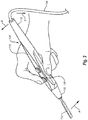
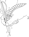
- Figure 2 which is an example useful for understanding the invention, which illustrates one of the most common manners by which physicians hold electrosurgical instrument 104 during an electrosurgical procedure.
- hand piece 110 is laid through the crook of the hand and is held in place by the middle finger and thumb.
- the index finger is placed on top of hand piece 110 to further hold hand piece 110 in place as well as to activate input devices 138.
- the flexibility, weight/moment-arm and drag characteristics of cable 108 and the connection location of cable 108 to hand piece 110 limit the ability of the physician during a surgical procedure.
- a physician While holding electrosurgical instrument 104 as shown in Figure 2 , a physician will perform electrosurgery by activating input devices 138 and moving electrode tip 112 into contact with the patient's tissue. To make contact between electrode tip 112 and the patient's tissue, the physician will move his or her wrist or fingers to adjust the position and/or orientation of electrosurgical instrument 104.
- the physician may move his or her wrist so that electrode tip 112 moves in the direction of arrow A toward the patient's tissue.
- proximal end 116 moves in the direction of arrow B.
- the weight of cable 108 constantly pulls proximal end 116 in the direction of arrow C.
- the weight of cable 108 resists the movement of proximal end 116 in the direction of arrow B.
- the resistance created by the weight of cable 108 is accentuated by the location at which cable 108 is connected to hand piece 110.
- a torque is created by applying a force at a distance from an axis or pivot point.
- the magnitude of the torque is a result of the magnitude of the applied force and the distance between the axis/pivot point and the location where the force is applied.
- the weight of cable 108 is the force that contributes to the generation of the resistive torque.
- the location at which cable 108 attaches to hand piece 110 and how hand piece 110 is held creates the lever arm through which the weight of cable 108 works to create the torque. More specifically, cable 108 enters hand piece 110 at or near proximal end 116.
- proximal end 116 When electrosurgical instrument 104 is held as shown in Figure 2 , proximal end 116 is positioned above and away from the crook of the physician's hand, which acts as the pivot point. The weight of cable 108 pulls down on proximal end 116, thereby creating a torque or moment-arm. Because the magnitude of the torque is dependent on the distance between the pivot point and the force, the further apart the connection point between cable 108 and hand piece 110 is away from the crook of the hand, the greater the torque will be. Understandably, the larger the torque is, the greater amount of resistance the physician will experience when manipulating electrosurgical instrument 104.
- the physician To overcome the resistance created by the weight of cable 108, the physician must exert additional energy to move electrosurgical instrument 104 into the desired orientation. Continuously working against the resistance created by cable 108 can cause the physician's hand, and/or wrist, and/or arm to become fatigued during an electrosurgical procedure. This fatigue can also lead to a loss of accuracy and precision in the performance of the procedure.
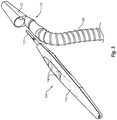
- Figure 3 illustrates an exploded view of fluid evacuation device 120 removed from electrosurgical instrument 104.
- Figure 4 illustrates a cross-sectional view of fluid evacuation device 120.
- Figure 5 illustrates a cross-sectional view of fluid evacuation device 120 mounted on electrosurgical instrument 104.
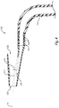
- Figure 6 illustrates electrosurgical instrument 104 with fluid evacuation device 120 mounted thereon and clips securing cable 108 and evacuation hose 124 together.
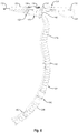
- Figures 7 and 8 illustrate exemplary manners of holding electrosurgical instrument 104 and fluid evacuation device 120.
- nozzle 122 includes an opening 126 in the distal end thereof. Opening 126 is sized to allow electrode tip 112 to extend therethrough. Additionally, opening 126 is sized to allow fluid to flow through opening 126 into nozzle 122 and around electrode tip 112.
- Nozzle 122 also includes a receptacle 128 that opens towards the proximal end of nozzle 122.
- Receptacle 128 is configured to receive and selectively retain therein at least a portion of the distal end or nose 118 of hand piece 110.
- Receptacle 128 may be shaped or otherwise formed to generally conform to nose 118 of hand piece 110, thereby creating a friction fit when hand piece 110 is inserted into nozzle 122. Additionally or alternatively, receptacle 128 may include other features that facilitate a secure connection between nozzle 122 and hand piece 110.
- an interior surface of receptacle 128 may include a deformable material (e.g., foam, rubber) that conforms to the shape of hand piece 110 to assist with retaining hand piece 110 therein as well as providing an effective seal between the two.
- receptacle 128 may include one or more clamps, clips, protrusions, or other features that selectively or permanently secure nozzle 122 onto distal end 118 of hand piece 110.
- nozzle 122 may be selectively or permanently connectable to hand piece 110.
- receptacle 128 and opening 126 are in fluid communication with one another and share a common axis A.
- electrode tip 112 passes through nozzle 122 and out of opening 126, as shown in Figure 5 .
- axis A of nozzle 122 is generally collinear with a longitudinal axis of electrosurgical instrument 104.
- Receptacle 128 is configured to limit how far electrosurgical instrument 104 may be inserted into nozzle 122. As illustrated in Figures 4 and 5 , receptacle 128 has a generally conical or tapered shape to limit the insertion depth of electrosurgical instrument 104. More specifically, receptacle 128 narrows closer to the distal end of nozzle 122. That is, receptacle 128 is wider near the proximal end of nozzle 122 than near the distal end of nozzle 122. As a result, when electrosurgical instrument 104 is being inserted into nozzle 122, hand piece 110 will eventually engage the interior of receptacle 128 such that hand piece 110 cannot be inserted any further into nozzle 122.
- nozzle 122 In addition to opening 126 and receptacle 128, nozzle 122 also includes a flow region 130. Flow region 130 is in fluid communication with opening 126 such that fluid drawn into nozzle 122 through opening 126 is able to pass through flow region 130. In the illustrated embodiment, flow region 130 forms an angle ⁇ with axis A of receptacle 128.
- nozzle 122 has a length (between the proximal and distal ends thereof) of about 3.81 cm ("1.5 inches”). In other embodiments, however, nozzle 122 may have a length of between about 1.27 cm ("0.5 inches”) and about 15.24 cm (“6 inches”). Similarly, while opening 126 is illustrated with a diameter of about 0.762 cm ("0.3 inches”), opening 126 may have a diameter of between about 0.508 cm ("0.2 inches”) and about 1.905 cm ("0.75 inches”).
- proximal opening to receptacle 128 may range from about 0.635 cm to about 2.54cm ("0.25 inches to about 1 inch").
- Hose mount 132 Extending proximally from nozzle 122, and particularly from the proximal end of flow region 130, is a hose mount 132 to which an end of evacuation hose 124 is connected.
- Hose mount 132 may be integrally formed with nozzle 122, or nozzle 122 and hose mount 132 may be formed separately and secured together thereafter.
- hose mount 132 includes ridges 134 formed on an outer surface thereof.
- An end of evacuation hose 124 is positioned around hose mount 132 and ridges 134 assist in retaining the end of evacuation hose 124 on hose mount 132.
- evacuation hose 124 may also be secured to hose mount 130 using other fasteners, such as zip-ties, clamps, adhesives, or combinations thereof. Still further, evacuation hose 124 may also be heat shrunk onto hose mount 132.
- hose mount 132 has a passageway 136 extending therethrough. Passageway 136 is in fluid communication with flow region 130 in nozzle 122. Fluid that is drawn into opening 126 may pass through flow region 130 and into passageway 136. Passageway 136 is also in fluid communication with a lumen in evacuation hose 124. Accordingly, fluid that is drawn into nozzle 122 may be conveyed away via evacuation hose 124.
- Hose mount 132 and passageway 136 are illustrated as having oval cross-sectional shapes. By forming hose mount 132 and passageway 136 with oval cross-sectional shapes, the height of hose mount 132 may be reduced without having to reduce the flow volume that may pass through hose mount 132. It is understood, however, that hose mount 132 and/or passageway 136 may have other cross-sectional shapes, including circular cross-sectional shapes.
- hose mount 132 is offset from axis A. Offsetting hose mount 132 from axis A causes hose mount 132 to be positioned to a side of hand piece 110. As can be seen in Figure 5 , for instance, hose mount 132 is disposed along the underside or belly of hand piece 110.
- hose mount 132 can vary from one embodiment to another, depending on various factors, including the electrosurgical instrument it is used with, the evacuation hose used in connection therewith, and the like.
- hose mount 132 has a length (between the proximal and distal ends thereof) of about 1 inch.
- hose mount 132 extends proximally along hand piece 110 to the region of hand piece generally below the user inputs 138 on electrosurgical instrument 104.
- hose mount 132 extends along hand piece 110 to the area below a distal user input 138.
- hose mount 132 is illustrated has having a length of about 2.54cm ("1 inch”), hose mount 132 may have a length of between about 0.508cm ("0.2 inches”) to about 7.62 cm (“3 inches”) or more. Similarly, passageway 136 may have an inner diameter of between about 0.508 cm ("0.2 inches”) and about 7.62 cm (“3 inches”). In other embodiments, hose mount 132 may be effectively incorporated into nozzle 122, rather than extending proximally therefrom. For instance, flow region 130 may have a receptacle that is configured to receive and retain an end of evacuation hose 124 therein.
- evacuation hose 124 may be relatively flexible. As a result, evacuation hose 124 may extend away from electrosurgical instrument 104 at various angles and from various positions (referred to herein after as "extension locations") along the length of electrosurgical instrument 104.
- evacuation hose 124 may include two or more sections that are connected together in a manner that allows for relative movement between adjacent sections.
- evacuation hose 124 may include a first section 124a and a second section 124b that are connected together via a swivel 140.
- Swivel 140 may include a first half and a second half that are able to rotate relative to one another.
- First section 124a may be connected to the first half of swivel 140 and second section 124b may be connected to the second half of swivel 140.
- the ability of the first and second halves of swivel 140 to rotate relative to one another enables first and second sections 124a, 124b of evacuation hose 124 to also rotate relative to one another.
- nozzle 122, hand piece 110, and first section 124a are able to move and rotate relative to second section 124b with less longitudinal rotational torque.
- evacuation hose 124 may be corrugated, convoluted, fluted, or have detents disposed on the outer surface thereof.
- evacuation hose 124 may not be corrugated, convoluted, fluted, or include detents thereon. Rather, evacuation hose 124 may have a smooth outer surface.
- each of clips 142 includes a ring disposed around evacuation hose 124 to secure clips 142 to evacuation hose 124.
- the rings of clips 142 may extend entirely around evacuation hose 124, or the rings may extend only partially around evacuation hose 124 so that evacuation hose 124 may be selectively removed from the rings through an opening.
- each of clips 142 also includes a hook in which cable 108 may be secured. Cable 108 may be selectively connected to clips 142 or permanently connected thereto.
- clips 142 are disposed on evacuation hose 124 at various locations. In some embodiments, clips 142 may be fixedly disposed at the various locations along the length of evacuation hose 124. In other embodiments, clips 142 may be movably disposed on evacuation hose 124 such that a user can adjust the position of one or more of clips 142 along the length of evacuation hose 124. Furthermore, although the present embodiment is illustrated with three clips 142, it is understood that other embodiments may include one or more clips 142.
- cable 108 and evacuation hose 124 may be connected together with mechanisms other than clips 142.
- cable 108 and evacuation hose 124 may be secured together with zip ties, cords, a hook and loop fastener, such as VELCRO, cohesive or self-adhesive tape, such as COBAN, and the like.
- VELCRO hook and loop fastener
- cohesive or self-adhesive tape such as COBAN, and the like.
- cable 108 and evacuation hose 124 can be secured together with any suitable fastener, whether the fastener provides a selective or permanent connection between cable 108 and evacuation hose 124.
- Securing cable 108 and evacuation hose 124 together can provide various benefits. For instance, when connected together as shown, cable 108 and evacuation hose 124 extend away from hand piece 110 together. As a result, cable 108 and evacuation hose 124 are less likely to become tangled with one another, a user, or other equipment.
- Securing cable 108 and evacuation hose 124 together as shown can also dramatically reduce the resistance typically created by cable 108.
- cable 108 extends out of proximal end 116 of hand piece 110. Rather than hanging down from proximal end 116 (as shown in Figure 2 ), however, cable 108 extends distally along the length of hand piece 110 until it meets and connects to evacuation hose 124.
- cable 108 and evacuation hose 124 extend away from hand piece 110 at about the same location along the length of hand piece 110. In the illustrated embodiment, the extension location of cable 108 and evacuation hose 124 is at about the middle of hand piece 110.
- a cable or hose that extends from a proximal end of a hand piece creates resistance, typically in the form of a torque, to the movement of the hand piece.
- the cable or hose resists the movement or reorientation of the hand piece. Accordingly, allowing the evacuation hose 124 and/or cable 108 to extend away from hand piece 110 at a more distally located position reduces the amount of resistance typically created by the cable or hose.
- having cable 108 and/or evacuation hose 124 extend away from hand piece 110 closer to the distal end of hand piece 110 also reduces the change is resistance experienced when moving or reorienting hand piece 110.
- the resistance created by a cable or hose changes. While the change in resistance may be due at least in part to the direction of movement or reorientation and/or the speed of the movement, the change in resistance is primarily due to the location along the length of the hand piece where the cable and/or hose extend away from the hand piece.
- the increased distance between the location where the cable and/or hose extend away from the hand piece and the pivot point of the hand piece creates a larger torque.
- the change in resistance during movement or reorientation of the hand piece is greater than the change in resistance created when the extension location is closer to the distal end of the hand piece.
- Devices 1-4 were standard electrosurgical instruments that include power cables extending from the proximal ends of the hand pieces.
- Device 5 consisted of Device 1 (a standard electrosurgical instrument) retrofitted with a smoke evacuation device.
- the smoke evacuation device used in connection with Device 5 included a nozzle that connected to the nose of the electrosurgical instrument and an evacuation hose that extended away from the electrosurgical instrument at the proximal end of the instrument.
- Devices 6-11 were electrosurgical instruments that include both power cables and smoke evacuation hoses extending from the proximal ends of the hand pieces.
- the torque associated with electrosurgical instrument 104 and fluid evacuation device 120 was also measured with cable 108 and evacuation hose 124 extending from hand piece 110 about 0.6 inches behind (i.e., in the proximal direction) the proximal-most user input button 138, similar to the configuration shown in Figure 6 .
- Table 1 includes the torques associated with the twelve devices when the hand pieces were in a level orientation (i.e., the proximal and distal ends of the hand pieces were at substantially the same height).
- Table 2 includes the torques associated with the twelve devices when the hand pieces were held at a 45° angle with the distal end of the hand piece being disposed lower than the proximal end.
- the torques were also measured when the hand pieces were held at different heights (i.e. 0.762m, 0.9144m, 1.0668m, 1.2192m) (("i.e., 2.5 ft, 3 ft, 3.5 ft, and 4 ft")).
- Tables 1 and 2 also include other basic information regarding each of the evaluated devices. This information includes the lengths of the hand pieces, the masses of the hand piece and associated cables/hoses, and the distances between the pivot points of the hand pieces and the ends of the hand pieces. To provide consistency throughout the samples, the pivot point for each hand piece was determined to be at the user input button positioned closest to the proximal end of the hand piece. TABLE 1 Height above floor Center of Proximal Input Button to Tip (in.) Center of Proximal Input Button to exit location (in) Total (in) Mass of hand piece, cord, & tubing (g) 2.5 ft 3.0 ft 3.5 ft 4.0 ft Torgue (oz.in.
- the power cables for the standard electrosurgical devices create torques ranging from 0.00459 Nm to 0.0247 Nm ("0.65 oz. in. to 3.5 oz. in.") in the horizontal orientation and from 0.00494 Nm to 0.0247 Nm ("0.7 oz. in. to 3.5 oz. in”). in the angled orientation.
- the power cables and hoses for Devices 5-10 create torques ranging from 0.0106 Nm to 0.0777 Nm ("1.5 oz. in. to 11 oz. in.”) or more in both the horizontal and angled orientations. It is observed that the torque for each device generally increases as the height of the hand piece increases. This is understandable since the length, and thus the weight, of the suspended portion of the power cable and/or evacuation hose increases as the height of the hand piece increases.
- cable 108 and evacuation hose 124 which extended away from hand piece 110 near user inputs 138, created no torque, or negligible levels of torque, in the horizontal orientation and only 2 oz. in. of torque in the angled orientation.
- the distally located extension location of cable 108 and evacuation hose 124 substantially or entirely eliminates the torque typically associated with cables and hoses extending from hand pieces.
- Figures 7 and 8 also illustrate exemplary manners of holding electrosurgical instrument 104 with fluid evacuation device 120 connected thereto.
- Figure 7 illustrates cable 108 and evacuation hose 124 extending away from hand piece 110 on the front side of the physician's palm so that cable 108 and evacuation hose 124 are positioned in the palm of the physician's hand.
- the physician may grasp cable 108 and evacuation hose 124 by wrapping some or all ofhis or her fingers around cable 108 and evacuation hose 124. While grasping cable 108 and evacuation hose 124, the physician may also hold hand piece 110 as shown in Figure 7 (e.g., between the thumb and middle finger, with the index finger on top to control input devices 138).
- cable 108 and evacuation hose 124 may act as a handle for electrosurgical instrument 104.
- cable 108 and/or evacuation hose 124 may be formed to provide stability to electrosurgical instrument 104.
- evacuation hose 124 and/or cable 108 may be formed of or include tubing that is stiff enough to maintain the position or orientation of hand piece 110 when evacuation hose 124 is used as a handle. More specifically, evacuation hose 124 and/or cable 108 may be stiff enough so that evacuation hose 124 and/or cable 108 maintains hand piece 110 in its current position even when a physician lets go of hand piece 110 and is only holding evacuation hose 124 and/or cable 108.
- evacuation hose 124 and/or cable 108 may be sized to comfortably fit within a physician's hand and allow for the physician to securely hold evacuation hose 124 and/or cable 108.
- evacuation hose 124 and/or cable 124 may individually or collectively have an outer diameter of between about 0.1 inches and about 3 inches. In one example embodiment, evacuation hose 124 has an outer diameter of about 0.5 inches. Evacuation hose 124 and/or cable 108 may also have some elastic flexibility that contributes to the above-noted functionality. For instance, evacuation hose 124 may be formed to allow for evacuation hose 124 to be angled or bent without collapsing or significantly reducing the inner lumen or flow channel therein. By way of example, the material used to form the evacuation hose 124 may allow evacuation hose 124 to have a bend radius of between about 0° and about 180°.
- evacuation hose 124 with a bend radius of about 180°, a swivel may be connected between evacuation hose 124 and hand piece 110 to allow evacuation hose 124 to extend away from hand piece 110 as shown in the Figures. In other embodiments, all or portions of evacuation hose 124 may be segmented and joined together to provide a moving joint flexibility.
- evacuation hose 124 may be formed from multiple sections.
- the sections of evacuation hose 124 may have diameters and/or flexibility characteristics that are difference from one another.
- a first section connected to the hand piece may be relatively stiff to provide the above-noted stability and grip functionalities.
- a second section connected to the first section may be more flexible than the first section.
- evacuation hose 124 and/or cable 108 may be formed by one or more cables and/or one or more hoses. Accordingly, the noted diameters and flexibilities may be a result of multiple hoses, cables, and/or combinations thereof. For instance, two or more hoses may have a combined diameter of between about 0.1 inches and about 3 inches.
- a physician may select to have cable 108 and/or evacuation hose 124 lay through the crook of his or her hand, as shown in Figure 8 , so that cable 108 and/or evacuation hose 124 extends down the crook of the hand towards the wrist.
- the fluid evacuation devices of the present disclosure may be used with such hand-held instruments as dental instruments (e.g., drills, polishing tools, scalers, compressed air tools, suction tools, irrigation tools, carries detection tools, water flossing tool (e.g., waterpik)), soldering tools (e.g., heated tools, smoke collection tools, de-soldering tools), high speed grinding and polishing tools (e.g., Dremel tools, carving tools, manicure tools, dental lab grinders/polishers), laser treatment instruments, laser surgical instruments, light probes, suction handles (e.g., Yankauer), blasting tools (e.g., sandblast, gritblast), shockwave therapy tools, ultrasonic therapy tools, ultrasonic probe tools,
- dental instruments e.g., drills, polishing tools, scalers, compressed air tools, suction tools, irrigation tools, carries detection tools, water flossing tool (e.g., waterpik)), soldering tools (e.g., heated tools, smoke
Claims (14)
- Dispositif d'évacuation de fluide (120) qui est attachable à un instrument manuel, le dispositif d'évacuation de fluide (120) comprenant :une buse (122) ayant une extrémité proximale et une extrémité distale, l'extrémité proximale ayant un réceptacle (128) configuré pour recevoir une partie de l'instrument manuel (104) dans celui-ci, l'extrémité distale ayant une ouverture (126) dans celle-ci à travers laquelle un fluide peut être aspiré dans la buse (122), la buse (122) ayant également une région d'écoulement (130) en communication fluidique avec l'ouverture (126) dans l'extrémité distale, la région d'écoulement (130) s'étendant à partir de l'extrémité distale vers l'extrémité proximale ;un support de tuyau flexible (132) associé à la buse (122), le support de tuyau flexible (132) ayant une voie de passage (136) s'étendant à travers celui-ci, la voie de passage (136) étant en communication fluidique avec la région d'écoulement (130) dans la buse (122) ; etun tuyau d'évacuation flexible (124), comprenant une première section de tuyau flexible (124a) et une seconde section de tuyau flexible (124b), une première extrémité de la première section (124a) étant raccordée au support de tuyau flexible (132) de telle sorte qu'une lumière dans le tuyau flexible d'évacuation (124) soit en communication fluidique avec la voie de passage (136) dans le support de tuyau flexible (132), caractérisé en ce que le tuyau flexible d'évacuation (124) comprend en outreun pivot (140) raccordé entre la première section (124a) et la seconde section (124b) pour permettre la rotation relative entre la première section (124a) et la seconde section (124b) pour réduire le couple rotationnel longitudinal.
- Dispositif d'évacuation de fluide (120) selon la revendication 1, dans lequel la buse (122) a un axe longitudinal s'étendant entre l'extrémité proximale et l'extrémité distale de celle-ci.
- Dispositif d'évacuation de fluide (120) selon la revendication 2, dans lequel la région d'écoulement (130) est disposée à un angle relatif à l'axe longitudinal de la buse (122).
- Dispositif d'évacuation de fluide (120) selon la revendication 2 ou 3, dans lequel le support de tuyau flexible (132) est décalé par rapport à l'axe longitudinal de la buse (122).
- Dispositif d'évacuation de fluide (120) selon l'une quelconque des revendications 2 à 4, dans lequel l'axe longitudinal est généralement aligné avec un axe longitudinal de l'instrument manuel (104) lorsque l'instrument manuel (104) est reçu dans le réceptacle (128).
- Dispositif d'évacuation de fluide (120) selon une quelconque revendication précédente, dans lequel, lorsque le dispositif d'évacuation de fluide (120) est attaché à l'instrument manuel (104), le tuyau flexible d'évacuation (124) s'étend à l'opposé de l'instrument manuel (104) entre les extrémités proximale (116) et distale (118) de l'instrument manuel (104).
- Dispositif d'évacuation de fluide (120) selon une quelconque revendication précédente, comprenant en outre un ou plusieurs éléments de fixation (142) configurés pour raccorder ensemble le tuyau flexible d'évacuation (124) et un câble électrique (108) de l'instrument manuel.
- Dispositif d'évacuation de fluide (120) selon la revendication 7, dans lequel les un ou plusieurs éléments de fixation (142) sont configurés pour raccorder ensemble au moins une partie d'une longueur du tuyau d'évacuation flexible (124) et au moins une partie d'une longueur du câble électrique (108) pour former une longueur raccordée du tuyau d'évacuation flexible (124) et du câble électrique (108), de telle sorte que la longueur raccordée du tuyau d'évacuation flexible (124) et du câble électrique (108) s'étende à l'opposé de l'instrument manuel (104) à un emplacement distal de l'extrémité proximale (116) de l'instrument manuel (104).
- Dispositif d'évacuation de fluide (120) selon une quelconque revendication précédente, dans lequel une longueur totale de la buse (122) et du support de tuyau flexible (132) est entre 5,1 cm (2 pouces) et 15,2 cm (6 pouces) ou entre 1,8 cm (0,7 pouces) et 15,2 cm (6 pouces).
- Dispositif d'évacuation de fluide (120) selon une quelconque revendication précédente, dans lequel le tuyau flexible d'évacuation (124) est configuré pour s'étendre à l'opposé d'un emplacement distal de l'instrument manuel pour créer un couple d'entre 0 kg cm (0 once pouce) et 0,14 kg cm (2 once pouce) sur l'instrument manuel (104).
- Dispositif d'évacuation de fluide (120) selon une quelconque revendication précédente, dans lequel au moins une partie du tuyau flexible d'évacuation (124) est configuré pour s'étendre à l'opposé de l'instrument manuel (104) et à travers la main d'un utilisateur de telle sorte que le tuyau flexible d'évacuation (124) puisse être tenu sous forme de poignée dans la main d'un utilisateur.
- Dispositif d'évacuation de fluide (120) selon la revendication 11, dans lequel la première section du tuyau flexible d'évacuation (124a) fournit une stabilité à l'instrument manuel lorsqu'il est tenu dans la main d'un utilisateur.
- Dispositif d'évacuation de fluide (120) selon la revendication 11, dans lequel la seconde section de tuyau flexible (124b) est plus flexible que la première section de tuyau flexible (124a).
- Dispositif d'évacuation de fluide (120) selon la revendication selon une quelconque revendication précédente, dans lequel l'instrument manuel (104) inclut une extrémité proximale (116), une extrémité distale (118), un point médian entre les extrémités proximale (116) et distale (118) et est sélectionné parmi le groupe constitué d'un instrument médical, d'un instrument dentaire, d'un outil de soudage, d'un outil de pyrogravure, d'une perceuse, et d'un applicateur d'adhésif, dans lequel la buse est configurée pour être montée sur l'extrémité distale (118) de l'instrument manuel (104), et la partie reçue par le réceptacle comprend une extrémité distale de l'instrument manuel.
Applications Claiming Priority (2)
| Application Number | Priority Date | Filing Date | Title |
|---|---|---|---|
| US13/831,560 US9259260B2 (en) | 2013-03-14 | 2013-03-14 | Fluid evacuation device |
| PCT/US2014/028094 WO2014152879A2 (fr) | 2013-03-14 | 2014-03-14 | Dispositif d'évacuation de fluide |
Publications (3)
| Publication Number | Publication Date |
|---|---|
| EP2968711A2 EP2968711A2 (fr) | 2016-01-20 |
| EP2968711A4 EP2968711A4 (fr) | 2016-11-16 |
| EP2968711B1 true EP2968711B1 (fr) | 2021-01-20 |
Family
ID=51530731
Family Applications (1)
| Application Number | Title | Priority Date | Filing Date |
|---|---|---|---|
| EP14770867.1A Active EP2968711B1 (fr) | 2013-03-14 | 2014-03-14 | Dispositif d'évacuation de fluide |
Country Status (13)
| Country | Link |
|---|---|
| US (1) | US9259260B2 (fr) |
| EP (1) | EP2968711B1 (fr) |
| JP (2) | JP6396416B2 (fr) |
| KR (1) | KR102212535B1 (fr) |
| CN (1) | CN105407936B (fr) |
| AU (1) | AU2014236546B2 (fr) |
| BR (1) | BR112015023010B1 (fr) |
| CA (1) | CA2906668C (fr) |
| IL (1) | IL241204B (fr) |
| MX (1) | MX362245B (fr) |
| NZ (1) | NZ712088A (fr) |
| WO (1) | WO2014152879A2 (fr) |
| ZA (1) | ZA201506697B (fr) |
Families Citing this family (13)
| Publication number | Priority date | Publication date | Assignee | Title |
|---|---|---|---|---|
| US9211137B2 (en) * | 2013-06-28 | 2015-12-15 | Misonix, Incorporated | Ultrasonic cutting blade with cooling liquid conduction |
| CA2956796A1 (fr) | 2014-08-12 | 2016-02-18 | Invuity, Inc. | Systeme electro-chirurgical eclaire et procede d'utilisation |
| CN115568937A (zh) | 2014-12-08 | 2023-01-06 | 英弗伊蒂股份有限公司 | 用于电外科照明和感测的方法和装置 |
| CN104783893A (zh) * | 2015-04-09 | 2015-07-22 | 天津大学 | 一种一次性高频电刀抽气套管 |
| CN110381865A (zh) * | 2016-11-23 | 2019-10-25 | Lcl企业公司 | 微晶研磨系统及其相关技术 |
| US10194975B1 (en) | 2017-07-11 | 2019-02-05 | Medtronic Advanced Energy, Llc | Illuminated and isolated electrosurgical apparatus |
| US10631916B2 (en) * | 2017-11-29 | 2020-04-28 | Megadyne Medical Products, Inc. | Filter connection for a smoke evacuation device |
| US11413109B2 (en) * | 2018-02-12 | 2022-08-16 | Gyrus Acmi, Inc. | Electrosurgical instrument with a functional element |
| EP3542740A1 (fr) * | 2018-03-20 | 2019-09-25 | BSN Medical GmbH | Dispositif de nettoyage de plaies par ultrasons |
| CN110193450A (zh) * | 2019-07-08 | 2019-09-03 | 广东电网有限责任公司 | 新型可视化气动打胶装置 |
| GB2587410B (en) * | 2019-09-27 | 2023-08-23 | Gyrus Medical Ltd | Footswitch for an electrosurgical instrument |
| WO2022035979A1 (fr) * | 2020-08-12 | 2022-02-17 | Patientpocket LLC | Système de détoxification de fumée chirurgicale autonome |
| KR102574347B1 (ko) | 2021-06-24 | 2023-09-01 | 김철중 | 손조절식 수술 전극장치 |
Family Cites Families (163)
| Publication number | Priority date | Publication date | Assignee | Title |
|---|---|---|---|---|
| US2311424A (en) | 1941-01-17 | 1943-02-16 | Jr Elyert J Weller | Vehicle |
| US2426214A (en) | 1941-12-15 | 1947-08-26 | Richfield Oil Corp | Insecticidal oil spray |
| US2329439A (en) | 1942-02-09 | 1943-09-14 | Buffalo Electro Chem Co | Hand truck |
| US2542019A (en) | 1948-07-22 | 1951-02-20 | Union Oil Co | Drilling fluids |
| US2530962A (en) | 1948-09-24 | 1950-11-21 | Du Pont | Formation of shaped articles from acrylonitrile polymers |
| GB1457411A (en) | 1973-03-14 | 1976-12-01 | Smiths Industries Ltd | Tubing adaptors |
| US4562838A (en) * | 1981-01-23 | 1986-01-07 | Walker William S | Electrosurgery instrument |
| US5451223B1 (en) | 1983-03-14 | 1998-11-03 | Ben Simhon Haim | Electrosurgical instrument |
| US5085657A (en) * | 1983-03-14 | 1992-02-04 | Ben Simhon Haim | Electrosurgical instrument |
| US4683884A (en) | 1986-04-11 | 1987-08-04 | Md Engineering | Noise attenuating smokeless surgical device |
| US4921492A (en) | 1988-05-31 | 1990-05-01 | Laser Technologies Group, Inc. | End effector for surgical plume evacuator |
| US5460602A (en) | 1989-01-23 | 1995-10-24 | Shapira; Nadiv | Smoke evacuator for smoke generating devices |
| US5192267A (en) | 1989-01-23 | 1993-03-09 | Nadiv Shapira | Vortex smoke remover for electrosurgical devices |
| US5066294A (en) | 1990-05-22 | 1991-11-19 | Ioan Cosmescu | Performance tester apparatus for a surgical laser system and method therefor |
| US5114422A (en) | 1989-12-11 | 1992-05-19 | Ioan Cosmescu | Laser laparoscope assembly and method therefor |
| US5312397A (en) | 1989-12-11 | 1994-05-17 | Ioan Cosmescu | Lens exchanger for a surgical laser system and method therefor |
| US5217457A (en) | 1990-03-15 | 1993-06-08 | Valleylab Inc. | Enhanced electrosurgical apparatus |
| US5244462A (en) | 1990-03-15 | 1993-09-14 | Valleylab Inc. | Electrosurgical apparatus |
| US5088997A (en) | 1990-03-15 | 1992-02-18 | Valleylab, Inc. | Gas coagulation device |
| US5108389A (en) | 1990-05-23 | 1992-04-28 | Ioan Cosmescu | Automatic smoke evacuator activator system for a surgical laser apparatus and method therefor |
| US5199944A (en) | 1990-05-23 | 1993-04-06 | Ioan Cosmescu | Automatic smoke evacuator system for a surgical laser apparatus and method therefor |
| US5318516A (en) | 1990-05-23 | 1994-06-07 | Ioan Cosmescu | Radio frequency sensor for automatic smoke evacuator system for a surgical laser and/or electrical apparatus and method therefor |
| US5154709A (en) * | 1990-09-04 | 1992-10-13 | Johnson Gerald W | Vacuum hood attachment for electrosurgical instruments |
| US5224944A (en) * | 1991-01-07 | 1993-07-06 | Elliott Martin P | Aspiration tip for a cautery handpiece |
| JP3115902B2 (ja) * | 1991-03-22 | 2000-12-11 | オリンパス光学工業株式会社 | 外科手術用ハンドピ−ス |
| US5181916A (en) | 1991-04-26 | 1993-01-26 | Sorenson Laboratories, Inc. | Surgical probe and smoke eliminator |
| US5160334A (en) | 1991-04-30 | 1992-11-03 | Utah Medical Products, Inc. | Electrosurgical generator and suction apparatus |
| US5195959A (en) | 1991-05-31 | 1993-03-23 | Paul C. Smith | Electrosurgical device with suction and irrigation |
| US5196007A (en) | 1991-06-07 | 1993-03-23 | Alan Ellman | Electrosurgical handpiece with activator |
| US5662647A (en) | 1991-07-22 | 1997-09-02 | Transamerican Technologies International | Electrode assembly for electrosurgical instrument |
| US5197963A (en) * | 1991-12-02 | 1993-03-30 | Everest Medical Corporation | Electrosurgical instrument with extendable sheath for irrigation and aspiration |
| US6770071B2 (en) | 1995-06-07 | 2004-08-03 | Arthrocare Corporation | Bladed electrosurgical probe |
| US7297145B2 (en) | 1997-10-23 | 2007-11-20 | Arthrocare Corporation | Bipolar electrosurgical clamp for removing and modifying tissue |
| US5432459A (en) | 1992-03-17 | 1995-07-11 | Conmed Corporation | Leakage capacitance compensating current sensor for current supplied to medical device loads with unconnected reference conductor |
| US5874052A (en) | 1992-05-15 | 1999-02-23 | Medtek Devices, Inc. | Antimicrobial filter for use in electrocautery or laser surgery |
| US5302354A (en) | 1992-06-26 | 1994-04-12 | Pall Corporation | Filtration device |
| US5358552A (en) | 1992-07-30 | 1994-10-25 | Pall Corporation | In situ filter cleaning system for gas streams |
| US5318565A (en) | 1992-11-12 | 1994-06-07 | Daniel B. Kuriloff | Suction cautery dissector |
| US5431650A (en) | 1992-12-11 | 1995-07-11 | Cosmescu; Ioan | Vortex hand piece shroud for automatic smoke evacuator system for a surgical laser apparatus and method therefor |
| US5693044A (en) | 1992-12-11 | 1997-12-02 | Cosmescu; Ioan | Telescopic surgical device and method therefor |
| AU671902B2 (en) | 1993-06-01 | 1996-09-12 | Conmed Corporation | Current sensor for medical devices with continuity monitor |
| US5423779A (en) | 1993-11-02 | 1995-06-13 | Yeh; Charles R. | High efficiency filtration particulate and smoke evacuator system |
| US5427570A (en) * | 1994-03-08 | 1995-06-27 | Chen; Ming-Jing | Exhaust hood system |
| US5520651A (en) | 1994-10-03 | 1996-05-28 | Conmed Corporation | Self releasing suction and irrigation apparatus and method of attachment |
| US5674219A (en) * | 1994-10-06 | 1997-10-07 | Donaldson Company, Inc. | Electrosurgical smoke evacuator |
| USD373190S (en) * | 1994-10-06 | 1996-08-27 | Donaldson Company, Inc. | Smoke evacuator for an electrocautery scalpel |
| US5575789A (en) | 1994-10-27 | 1996-11-19 | Valleylab Inc. | Energizable surgical tool safety device and method |
| US5830214A (en) | 1994-11-08 | 1998-11-03 | Heartport, Inc. | Fluid-evacuating electrosurgical device |
| US5458586A (en) | 1994-11-14 | 1995-10-17 | Pall Corporation | Universal connector for vacuum systems |
| US5613966A (en) | 1994-12-21 | 1997-03-25 | Valleylab Inc | System and method for accessory rate control |
| US5507535A (en) * | 1995-01-09 | 1996-04-16 | Mckamey; Floyd | Conduit swivel connector |
| JPH10503408A (ja) | 1995-02-03 | 1998-03-31 | ヴァリーラブ・インコーポレーテッド | ペンシルと組み合わせた電気外科用吸引器 |
| USD372086S (en) | 1995-02-03 | 1996-07-23 | Valleylab Inc. | Aspirator attachment for a surgical device |
| US6063081A (en) | 1995-02-22 | 2000-05-16 | Medtronic, Inc. | Fluid-assisted electrocautery device |
| US7393351B2 (en) | 1995-06-07 | 2008-07-01 | Arthrocare Corporation | Apparatus and methods for treating cervical inter-vertebral discs |
| US6837888B2 (en) | 1995-06-07 | 2005-01-04 | Arthrocare Corporation | Electrosurgical probe with movable return electrode and methods related thereto |
| US6458125B1 (en) | 1995-07-10 | 2002-10-01 | I. C. Medical, Inc. | Electro-surgical unit pencil apparatus and method therefor |
| WO1997014364A1 (fr) * | 1995-10-20 | 1997-04-24 | Donaldson Company, Inc. | Evacuation de fumees electrochirurgicales et systeme correspondant |
| US7270661B2 (en) | 1995-11-22 | 2007-09-18 | Arthocare Corporation | Electrosurgical apparatus and methods for treatment and removal of tissue |
| US5626568A (en) | 1995-12-26 | 1997-05-06 | Acuderm Inc. | Smoke evacuation apparatus |
| US5769702A (en) * | 1996-02-01 | 1998-06-23 | Sorenson Critical Care, Inc. | Variable positioning gaseous conduit orifice and method of use |
| US6117134A (en) | 1996-02-14 | 2000-09-12 | Cunningham; James Steven | Instrument for suction electrosurgery |
| US5609573A (en) | 1996-02-28 | 1997-03-11 | Conmed Corporation | Electrosurgical suction/irrigation instrument |
| USD384148S (en) * | 1996-03-18 | 1997-09-23 | Donaldson Company, Inc. | Smoke evacuator for an electrocautery scalpel |
| DE19706269A1 (de) | 1996-03-21 | 1997-09-25 | Valleylab Inc | Instrument zur gasangereicherten Elektrochirurgie |
| US5928137A (en) * | 1996-05-03 | 1999-07-27 | Green; Philip S. | System and method for endoscopic imaging and endosurgery |
| WO1998001075A1 (fr) | 1996-07-04 | 1998-01-15 | Erbe Elektromedizin Gmbh | Electrode chirurgicale deplaçable axialement, assistee par un gaz |
| US5836909A (en) | 1996-09-13 | 1998-11-17 | Cosmescu; Ioan | Automatic fluid control system for use in open and laparoscopic laser surgery and electrosurgery and method therefor |
| US5797901A (en) | 1996-09-20 | 1998-08-25 | Cosmescu; Ioan | Automatic activation system for a medical diagnostic monitoring and surgical apparatus and method therefore |
| US7112199B2 (en) | 1996-09-20 | 2006-09-26 | Ioan Cosmescu | Multifunctional telescopic monopolar/bipolar surgical device and method therefore |
| US6355034B2 (en) | 1996-09-20 | 2002-03-12 | Ioan Cosmescu | Multifunctional telescopic monopolar/bipolar surgical device and method therefor |
| US6099525A (en) | 1996-10-07 | 2000-08-08 | Cosmescu; Ioan | Removable shroud for receiving a pencil used in electro-surgery |
| US6045596A (en) | 1997-04-07 | 2000-04-04 | Medtek Devices, Inc. | Filter system to remove a contaminant from a fluid stream |
| US6053886A (en) | 1997-08-12 | 2000-04-25 | Medtek Devices, Inc. | Switch apparatus for operating an evacuator |
| US6110259A (en) | 1997-11-21 | 2000-08-29 | Jlj International, Inc. | Smoke evacuation system |
| CA2542019A1 (fr) | 1997-11-21 | 1999-07-01 | Jlj Medical Devices International, Llc | Systeme d'evacuation de fumee |
| AU746015B2 (en) | 1998-04-17 | 2002-04-11 | Innovative Surgical Technologies, Inc. | Evacuator |
| US6942650B1 (en) | 1998-04-17 | 2005-09-13 | Innovative Surgical Technologies, Inc. | Evacuator |
| US6663610B1 (en) | 1998-04-17 | 2003-12-16 | Leonard S. Schultz, M.D. | Smoke evacuation system |
| US6001077A (en) | 1998-05-26 | 1999-12-14 | Ellman; Alan G. | Vacuum wand for surgical smoke plume evacuation system |
| US6706039B2 (en) | 1998-07-07 | 2004-03-16 | Medtronic, Inc. | Method and apparatus for creating a bi-polar virtual electrode used for the ablation of tissue |
| US7435247B2 (en) | 1998-08-11 | 2008-10-14 | Arthrocare Corporation | Systems and methods for electrosurgical tissue treatment |
| US7329253B2 (en) | 2003-12-09 | 2008-02-12 | Rubicor Medical, Inc. | Suction sleeve and interventional devices having such a suction sleeve |
| US6146353A (en) | 1998-09-22 | 2000-11-14 | Sherwood Services Ag | Smoke extraction device |
| US6544210B1 (en) | 1998-10-22 | 2003-04-08 | Gregory J. Trudel | Disposable laparoscopic smoke evacuation system |
| JP3602794B2 (ja) | 1998-11-16 | 2004-12-15 | イアン コスメスク, | 多機能型入れ子式電気外科器具 |
| CA2707676A1 (fr) | 1998-11-16 | 2000-05-25 | I.C. Medical, Inc. | Instrument electrochirurgical multifonctionnel, et methode connexe |
| US6576033B1 (en) | 1998-11-30 | 2003-06-10 | Pall Corporation | Filter for use in medical procedures |
| DE19860689C2 (de) | 1998-12-29 | 2001-07-05 | Erbe Elektromedizin | Verfahren zum Steuern einer Vorrichtung zum Entfernen von Rauch sowie Vorrichtung zur Durchführung des Verfahrens |
| US6231571B1 (en) | 1999-05-03 | 2001-05-15 | Alan G. Ellman | Electrosurgical handpiece for treating tissue |
| USD426883S (en) * | 1999-07-22 | 2000-06-20 | Surgiform Technology, Ltd. | Cauterization smoke evacuator |
| US6379350B1 (en) | 1999-10-05 | 2002-04-30 | Oratec Interventions, Inc. | Surgical instrument for ablation and aspiration |
| US6306135B1 (en) | 1999-11-22 | 2001-10-23 | Alan G. Ellman | Forehead lift suction probe |
| US7041101B2 (en) | 1999-12-27 | 2006-05-09 | Neothermia Corporation | Electrosurgical accessing of tissue with controlled collateral thermal phenomena |
| CA2299752A1 (fr) * | 2000-02-28 | 2001-08-28 | Cst Coldswitch Technologies Inc. | Stylet d'electrochirurgie avec dispositif d'evacuation de la fumee |
| US6293945B1 (en) | 2000-03-06 | 2001-09-25 | Everest Medical Corporation | Electrosurgical instrument with suction capability |
| EP1188415A3 (fr) | 2000-09-08 | 2002-05-08 | Pall Corporation | canule |
| US6530924B1 (en) | 2000-11-03 | 2003-03-11 | Alan G. Ellman | Electrosurgical tonsilar and adenoid electrode |
| US20020103485A1 (en) | 2000-12-05 | 2002-08-01 | Ivan Melnyk | Electrosurgical pencil with a smoke evacuating blade |
| US20020072739A1 (en) | 2000-12-07 | 2002-06-13 | Roberta Lee | Methods and devices for radiofrequency electrosurgery |
| DE60220019T2 (de) | 2001-01-29 | 2008-01-10 | JLJ Medical Devices, International, LLC, St. Louis Park | Fluid- und Bioaerosol-Handhabung |
| US6923804B2 (en) * | 2001-07-12 | 2005-08-02 | Neothermia Corporation | Electrosurgical generator |
| JP2003048496A (ja) * | 2001-08-07 | 2003-02-18 | Yazaki Corp | 電力分配システム及び中間コネクタ |
| AU2002362310A1 (en) | 2001-09-14 | 2003-04-01 | Arthrocare Corporation | Methods and apparatus for treating intervertebral discs |
| US6524307B1 (en) | 2001-10-05 | 2003-02-25 | Medtek Devices, Inc. | Smoke evacuation apparatus |
| US6616658B2 (en) * | 2001-11-08 | 2003-09-09 | Leonard Ineson | Electrosurgical pencil |
| US6669695B2 (en) | 2002-01-15 | 2003-12-30 | Giancarlo Luigi | Multifunctional electrosurgical instrument |
| US20030181904A1 (en) | 2002-01-23 | 2003-09-25 | Levine Andy H. | Electrosurgical cutting, coagulating and suction instrument |
| US6585791B1 (en) | 2002-01-29 | 2003-07-01 | Jon C. Garito | Smoke plume evacuation filtration system |
| US7247161B2 (en) * | 2002-03-22 | 2007-07-24 | Gyrus Ent L.L.C. | Powered surgical apparatus, method of manufacturing powered surgical apparatus, and method of using powered surgical apparatus |
| US6749608B2 (en) | 2002-08-05 | 2004-06-15 | Jon C. Garito | Adenoid curette electrosurgical probe |
| US7004939B2 (en) | 2002-09-03 | 2006-02-28 | Dale Victor Mackay | Electrosurgical apparatus |
| USD493530S1 (en) * | 2003-02-04 | 2004-07-27 | Sherwood Services Ag | Electrosurgical pencil with slide activator |
| CN1233300C (zh) | 2003-02-19 | 2005-12-28 | 苏英 | 多功能手术解剖器 |
| EP1707146A3 (fr) | 2003-05-15 | 2008-02-27 | Covidien AG | Système pour l'activation d'un instrument électrochirurgical |
| US20050000196A1 (en) | 2003-07-03 | 2005-01-06 | Schultz Leonard S. | Smoke evacuation system |
| US7494473B2 (en) | 2003-07-30 | 2009-02-24 | Intact Medical Corp. | Electrical apparatus and system with improved tissue capture component |
| AU2004273890A1 (en) | 2003-09-15 | 2005-03-31 | Robert O. Dean | Operating room smoke evacuator with integrated vacuum motor and filter |
| EP1902682B1 (fr) * | 2003-11-14 | 2017-01-11 | Lina Medical ApS | Crayon électrochirurgical de longueur réglable doté de moyens d'aspiration |
| US7241294B2 (en) | 2003-11-19 | 2007-07-10 | Sherwood Services Ag | Pistol grip electrosurgical pencil with manual aspirator/irrigator and methods of using the same |
| US7491200B2 (en) | 2004-03-26 | 2009-02-17 | Arthrocare Corporation | Method for treating obstructive sleep disorder includes removing tissue from base of tongue |
| USD555803S1 (en) | 2004-12-03 | 2007-11-20 | Garito Jon C | Smoke evacuation system |
| US7294116B1 (en) | 2005-01-03 | 2007-11-13 | Ellman Alan G | Surgical smoke plume evacuation system |
| US7761188B2 (en) | 2005-04-04 | 2010-07-20 | Medtek Devices, Inc. | Fluid evacuation system with two-way communication filter |
| US7500974B2 (en) | 2005-06-28 | 2009-03-10 | Covidien Ag | Electrode with rotatably deployable sheath |
| US20070000501A1 (en) | 2005-07-01 | 2007-01-04 | Wert Lindsay T | Surgical procedure supplemental accessory controller and method utilizing turn-on and turn-off time delays |
| DK1928518T3 (en) | 2005-09-27 | 2016-08-01 | Allegiance Corp | MEDICAL SUCTION AND douche |
| US8414576B2 (en) * | 2005-12-02 | 2013-04-09 | Ioan Cosmescu | Swivel device for electrosurgery pencil and surgical smoke evacuation |
| US20070129722A1 (en) * | 2005-12-02 | 2007-06-07 | Ioan Cosmescu | Swivel device for improved surgical smoke evacuation |
| US7947039B2 (en) | 2005-12-12 | 2011-05-24 | Covidien Ag | Laparoscopic apparatus for performing electrosurgical procedures |
| US20070249990A1 (en) | 2006-04-20 | 2007-10-25 | Ioan Cosmescu | Automatic smoke evacuator and insufflation system for surgical procedures |
| US7621911B2 (en) | 2006-04-27 | 2009-11-24 | Kirwan Surgical Products, Inc. | Disposable/removable tubing set for use with an electrosurgical instrument |
| US20070265615A1 (en) | 2006-05-09 | 2007-11-15 | Haim Ben-Simhon | Electrosurgical instrument with suction, irrigation and means to collect blood |
| US7794457B2 (en) | 2006-09-28 | 2010-09-14 | Covidien Ag | Transformer for RF voltage sensing |
| US8187272B2 (en) | 2006-10-06 | 2012-05-29 | Biomedcraft Designs, Inc. | Surgical instrument for coagulation and suction |
| US7780201B2 (en) * | 2006-10-13 | 2010-08-24 | Medela Holding Ag | Tube connector with three part construction and latching component |
| AU2008223473B2 (en) | 2007-03-01 | 2014-01-09 | Medtek Devices, Inc. Dba/ Buffalo Filter | Wick and relief valve for disposable laparscopic smoke evacuation system |
| US8057470B2 (en) | 2007-08-30 | 2011-11-15 | Conmed Corporation | Integrated smoke evacuation electrosurgical pencil and method |
| US20090069802A1 (en) | 2007-09-06 | 2009-03-12 | Garito Jon C | Electrosurgical electrode and method for use |
| US20090125023A1 (en) * | 2007-11-13 | 2009-05-14 | Cytyc Corporation | Electrosurgical Instrument |
| US8172836B2 (en) | 2008-08-11 | 2012-05-08 | Tyco Healthcare Group Lp | Electrosurgical system having a sensor for monitoring smoke or aerosols |
| US8529564B2 (en) * | 2008-09-23 | 2013-09-10 | Jung Wu | Medical electrocautery instrument assistant device |
| US8690872B2 (en) | 2008-11-14 | 2014-04-08 | Prash Jayaraj | Surgical pencil enabling suction |
| USD616986S1 (en) | 2008-12-19 | 2010-06-01 | Conmed Corporation | Surgical smoke evacuator |
| US8137345B2 (en) | 2009-01-05 | 2012-03-20 | Peak Surgical, Inc. | Electrosurgical devices for tonsillectomy and adenoidectomy |
| US8882768B2 (en) * | 2009-04-24 | 2014-11-11 | Megadyne Medical Products, Inc. | Hand piece with adjustable utility conduit |
| US8882767B2 (en) * | 2009-04-24 | 2014-11-11 | Megadyne Medical Products, Inc. | Electrosurgical instrument with adjustable utility conduit |
| US8211103B2 (en) * | 2009-04-24 | 2012-07-03 | Megadyne Medical Products, Inc. | Electrosurgical instrument with adjustable power cable |
| US8317786B2 (en) | 2009-09-25 | 2012-11-27 | AthroCare Corporation | System, method and apparatus for electrosurgical instrument with movable suction sheath |
| US8323279B2 (en) | 2009-09-25 | 2012-12-04 | Arthocare Corporation | System, method and apparatus for electrosurgical instrument with movable fluid delivery sheath |
| US20110077645A1 (en) | 2009-09-29 | 2011-03-31 | San-Chih Yang Lin | Electrosurgical Pencil with Synchronous Evacuation Function |
| US9289261B2 (en) | 2010-02-04 | 2016-03-22 | Buffalo Filter Llc | Electrosurgical device with vacuum port |
| US8992524B1 (en) | 2010-10-07 | 2015-03-31 | Alan G. Ellman | Electrosurgical Cobb elevator instrument |
| US9164500B2 (en) | 2011-01-11 | 2015-10-20 | Buffalo Filter Llc | Method and device for remote control of an apparatus |
| US9061234B2 (en) | 2011-01-14 | 2015-06-23 | Pall Corporation | Gas filter assemblies and methods for filtering gases |
| US8518018B2 (en) | 2011-02-04 | 2013-08-27 | Noah Mark Minskoff | Apparatus and method for electrosurgical suction |
| US8932292B2 (en) | 2011-02-04 | 2015-01-13 | Integrated Surgical LLC | Apparatus and method for electrosurgical suction |
| US10595934B2 (en) | 2011-05-02 | 2020-03-24 | I.C. Medical, Inc. | Electrosurgical unit pencil apparatus and shroud having directed illumination |
| US9554867B2 (en) | 2011-05-06 | 2017-01-31 | I.C. Medical, Inc. | Light attachment device for electrosurgical pencil and electrosurgical pencil attachments |
| EP2965704B1 (fr) | 2011-05-19 | 2017-11-29 | Cimpax ApS | Dispositif d'extension pour un crayon électrochirurgical avec un canal d'aspiration |
| US8870864B2 (en) | 2011-10-28 | 2014-10-28 | Medtronic Advanced Energy Llc | Single instrument electrosurgery apparatus and its method of use |
| US9101363B2 (en) | 2012-08-10 | 2015-08-11 | William J. Zinnanti | Cautery electrode with multi-channel insulated shaft |
| USD709196S1 (en) * | 2013-03-15 | 2014-07-15 | Megadyne Medical Products, Inc. | Hand piece |
-
2013
- 2013-03-14 US US13/831,560 patent/US9259260B2/en active Active
-
2014
- 2014-03-14 JP JP2016502702A patent/JP6396416B2/ja active Active
- 2014-03-14 MX MX2015012130A patent/MX362245B/es active IP Right Grant
- 2014-03-14 WO PCT/US2014/028094 patent/WO2014152879A2/fr active Application Filing
- 2014-03-14 CN CN201480027756.3A patent/CN105407936B/zh active Active
- 2014-03-14 EP EP14770867.1A patent/EP2968711B1/fr active Active
- 2014-03-14 BR BR112015023010-5A patent/BR112015023010B1/pt not_active IP Right Cessation
- 2014-03-14 AU AU2014236546A patent/AU2014236546B2/en not_active Ceased
- 2014-03-14 CA CA2906668A patent/CA2906668C/fr not_active Expired - Fee Related
- 2014-03-14 KR KR1020157028124A patent/KR102212535B1/ko active IP Right Grant
- 2014-03-14 NZ NZ712088A patent/NZ712088A/en not_active IP Right Cessation
-
2015
- 2015-09-06 IL IL241204A patent/IL241204B/en not_active IP Right Cessation
- 2015-09-10 ZA ZA2015/06697A patent/ZA201506697B/en unknown
-
2018
- 2018-01-18 JP JP2018006244A patent/JP6591575B2/ja active Active
Non-Patent Citations (1)
| Title |
|---|
| None * |
Also Published As
| Publication number | Publication date |
|---|---|
| NZ712088A (en) | 2019-02-22 |
| BR112015023010A2 (pt) | 2017-07-18 |
| KR20150127198A (ko) | 2015-11-16 |
| AU2014236546B2 (en) | 2018-07-05 |
| WO2014152879A3 (fr) | 2014-12-04 |
| IL241204A0 (en) | 2015-11-30 |
| WO2014152879A2 (fr) | 2014-09-25 |
| CN105407936A (zh) | 2016-03-16 |
| JP6396416B2 (ja) | 2018-09-26 |
| JP2018079351A (ja) | 2018-05-24 |
| EP2968711A4 (fr) | 2016-11-16 |
| KR102212535B1 (ko) | 2021-02-08 |
| EP2968711A2 (fr) | 2016-01-20 |
| AU2014236546A1 (en) | 2015-10-08 |
| JP6591575B2 (ja) | 2019-10-16 |
| JP2016512737A (ja) | 2016-05-09 |
| IL241204B (en) | 2020-06-30 |
| US9259260B2 (en) | 2016-02-16 |
| CA2906668A1 (fr) | 2014-09-25 |
| ZA201506697B (en) | 2017-03-29 |
| CN105407936B (zh) | 2019-12-31 |
| MX2015012130A (es) | 2016-06-02 |
| MX362245B (es) | 2019-01-09 |
| US20140276469A1 (en) | 2014-09-18 |
| CA2906668C (fr) | 2021-06-15 |
| BR112015023010B1 (pt) | 2022-02-15 |
Similar Documents
| Publication | Publication Date | Title |
|---|---|---|
| EP2968711B1 (fr) | Dispositif d'évacuation de fluide | |
| AU2018203693B2 (en) | Electrosurgical instrument | |
| US8882768B2 (en) | Hand piece with adjustable utility conduit | |
| US8882767B2 (en) | Electrosurgical instrument with adjustable utility conduit | |
| EP2682066B1 (fr) | Pièce à main avec conduit d'utilité ajustable | |
| EP3471640B1 (fr) | Instrument portatif pivotant | |
| TW201907878A (zh) | 具有撓性電路的轉動儀器 |
Legal Events
| Date | Code | Title | Description |
|---|---|---|---|
| PUAI | Public reference made under article 153(3) epc to a published international application that has entered the european phase |
Free format text: ORIGINAL CODE: 0009012 |
|
| 17P | Request for examination filed |
Effective date: 20150911 |
|
| AK | Designated contracting states |
Kind code of ref document: A2 Designated state(s): AL AT BE BG CH CY CZ DE DK EE ES FI FR GB GR HR HU IE IS IT LI LT LU LV MC MK MT NL NO PL PT RO RS SE SI SK SM TR |
|
| AX | Request for extension of the european patent |
Extension state: BA ME |
|
| DAX | Request for extension of the european patent (deleted) | ||
| A4 | Supplementary search report drawn up and despatched |
Effective date: 20161014 |
|
| RIC1 | Information provided on ipc code assigned before grant |
Ipc: A61M 1/00 20060101AFI20161010BHEP |
|
| STAA | Information on the status of an ep patent application or granted ep patent |
Free format text: STATUS: EXAMINATION IS IN PROGRESS |
|
| 17Q | First examination report despatched |
Effective date: 20190208 |
|
| GRAP | Despatch of communication of intention to grant a patent |
Free format text: ORIGINAL CODE: EPIDOSNIGR1 |
|
| STAA | Information on the status of an ep patent application or granted ep patent |
Free format text: STATUS: GRANT OF PATENT IS INTENDED |
|
| INTG | Intention to grant announced |
Effective date: 20200805 |
|
| GRAS | Grant fee paid |
Free format text: ORIGINAL CODE: EPIDOSNIGR3 |
|
| GRAA | (expected) grant |
Free format text: ORIGINAL CODE: 0009210 |
|
| STAA | Information on the status of an ep patent application or granted ep patent |
Free format text: STATUS: THE PATENT HAS BEEN GRANTED |
|
| AK | Designated contracting states |
Kind code of ref document: B1 Designated state(s): AL AT BE BG CH CY CZ DE DK EE ES FI FR GB GR HR HU IE IS IT LI LT LU LV MC MK MT NL NO PL PT RO RS SE SI SK SM TR |
|
| REG | Reference to a national code |
Ref country code: GB Ref legal event code: FG4D |
|
| REG | Reference to a national code |
Ref country code: CH Ref legal event code: EP |
|
| REG | Reference to a national code |
Ref country code: DE Ref legal event code: R096 Ref document number: 602014074388 Country of ref document: DE |
|
| REG | Reference to a national code |
Ref country code: AT Ref legal event code: REF Ref document number: 1355801 Country of ref document: AT Kind code of ref document: T Effective date: 20210215 |
|
| REG | Reference to a national code |
Ref country code: IE Ref legal event code: FG4D |
|
| REG | Reference to a national code |
Ref country code: NL Ref legal event code: FP |
|
| REG | Reference to a national code |
Ref country code: LT Ref legal event code: MG9D |
|
| REG | Reference to a national code |
Ref country code: AT Ref legal event code: MK05 Ref document number: 1355801 Country of ref document: AT Kind code of ref document: T Effective date: 20210120 |
|
| PG25 | Lapsed in a contracting state [announced via postgrant information from national office to epo] |
Ref country code: FI Free format text: LAPSE BECAUSE OF FAILURE TO SUBMIT A TRANSLATION OF THE DESCRIPTION OR TO PAY THE FEE WITHIN THE PRESCRIBED TIME-LIMIT Effective date: 20210120 Ref country code: GR Free format text: LAPSE BECAUSE OF FAILURE TO SUBMIT A TRANSLATION OF THE DESCRIPTION OR TO PAY THE FEE WITHIN THE PRESCRIBED TIME-LIMIT Effective date: 20210421 Ref country code: HR Free format text: LAPSE BECAUSE OF FAILURE TO SUBMIT A TRANSLATION OF THE DESCRIPTION OR TO PAY THE FEE WITHIN THE PRESCRIBED TIME-LIMIT Effective date: 20210120 Ref country code: PT Free format text: LAPSE BECAUSE OF FAILURE TO SUBMIT A TRANSLATION OF THE DESCRIPTION OR TO PAY THE FEE WITHIN THE PRESCRIBED TIME-LIMIT Effective date: 20210520 Ref country code: LT Free format text: LAPSE BECAUSE OF FAILURE TO SUBMIT A TRANSLATION OF THE DESCRIPTION OR TO PAY THE FEE WITHIN THE PRESCRIBED TIME-LIMIT Effective date: 20210120 Ref country code: BG Free format text: LAPSE BECAUSE OF FAILURE TO SUBMIT A TRANSLATION OF THE DESCRIPTION OR TO PAY THE FEE WITHIN THE PRESCRIBED TIME-LIMIT Effective date: 20210420 Ref country code: NO Free format text: LAPSE BECAUSE OF FAILURE TO SUBMIT A TRANSLATION OF THE DESCRIPTION OR TO PAY THE FEE WITHIN THE PRESCRIBED TIME-LIMIT Effective date: 20210420 |
|
| PG25 | Lapsed in a contracting state [announced via postgrant information from national office to epo] |
Ref country code: SE Free format text: LAPSE BECAUSE OF FAILURE TO SUBMIT A TRANSLATION OF THE DESCRIPTION OR TO PAY THE FEE WITHIN THE PRESCRIBED TIME-LIMIT Effective date: 20210120 Ref country code: RS Free format text: LAPSE BECAUSE OF FAILURE TO SUBMIT A TRANSLATION OF THE DESCRIPTION OR TO PAY THE FEE WITHIN THE PRESCRIBED TIME-LIMIT Effective date: 20210120 Ref country code: LV Free format text: LAPSE BECAUSE OF FAILURE TO SUBMIT A TRANSLATION OF THE DESCRIPTION OR TO PAY THE FEE WITHIN THE PRESCRIBED TIME-LIMIT Effective date: 20210120 Ref country code: PL Free format text: LAPSE BECAUSE OF FAILURE TO SUBMIT A TRANSLATION OF THE DESCRIPTION OR TO PAY THE FEE WITHIN THE PRESCRIBED TIME-LIMIT Effective date: 20210120 Ref country code: AT Free format text: LAPSE BECAUSE OF FAILURE TO SUBMIT A TRANSLATION OF THE DESCRIPTION OR TO PAY THE FEE WITHIN THE PRESCRIBED TIME-LIMIT Effective date: 20210120 |
|
| PG25 | Lapsed in a contracting state [announced via postgrant information from national office to epo] |
Ref country code: IS Free format text: LAPSE BECAUSE OF FAILURE TO SUBMIT A TRANSLATION OF THE DESCRIPTION OR TO PAY THE FEE WITHIN THE PRESCRIBED TIME-LIMIT Effective date: 20210520 |
|
| REG | Reference to a national code |
Ref country code: DE Ref legal event code: R097 Ref document number: 602014074388 Country of ref document: DE |
|
| PG25 | Lapsed in a contracting state [announced via postgrant information from national office to epo] |
Ref country code: MC Free format text: LAPSE BECAUSE OF FAILURE TO SUBMIT A TRANSLATION OF THE DESCRIPTION OR TO PAY THE FEE WITHIN THE PRESCRIBED TIME-LIMIT Effective date: 20210120 Ref country code: EE Free format text: LAPSE BECAUSE OF FAILURE TO SUBMIT A TRANSLATION OF THE DESCRIPTION OR TO PAY THE FEE WITHIN THE PRESCRIBED TIME-LIMIT Effective date: 20210120 Ref country code: CZ Free format text: LAPSE BECAUSE OF FAILURE TO SUBMIT A TRANSLATION OF THE DESCRIPTION OR TO PAY THE FEE WITHIN THE PRESCRIBED TIME-LIMIT Effective date: 20210120 Ref country code: SM Free format text: LAPSE BECAUSE OF FAILURE TO SUBMIT A TRANSLATION OF THE DESCRIPTION OR TO PAY THE FEE WITHIN THE PRESCRIBED TIME-LIMIT Effective date: 20210120 |
|
| REG | Reference to a national code |
Ref country code: CH Ref legal event code: PL |
|
| PLBE | No opposition filed within time limit |
Free format text: ORIGINAL CODE: 0009261 |
|
| STAA | Information on the status of an ep patent application or granted ep patent |
Free format text: STATUS: NO OPPOSITION FILED WITHIN TIME LIMIT |
|
| PG25 | Lapsed in a contracting state [announced via postgrant information from national office to epo] |
Ref country code: ES Free format text: LAPSE BECAUSE OF FAILURE TO SUBMIT A TRANSLATION OF THE DESCRIPTION OR TO PAY THE FEE WITHIN THE PRESCRIBED TIME-LIMIT Effective date: 20210120 Ref country code: DK Free format text: LAPSE BECAUSE OF FAILURE TO SUBMIT A TRANSLATION OF THE DESCRIPTION OR TO PAY THE FEE WITHIN THE PRESCRIBED TIME-LIMIT Effective date: 20210120 Ref country code: SK Free format text: LAPSE BECAUSE OF FAILURE TO SUBMIT A TRANSLATION OF THE DESCRIPTION OR TO PAY THE FEE WITHIN THE PRESCRIBED TIME-LIMIT Effective date: 20210120 Ref country code: RO Free format text: LAPSE BECAUSE OF FAILURE TO SUBMIT A TRANSLATION OF THE DESCRIPTION OR TO PAY THE FEE WITHIN THE PRESCRIBED TIME-LIMIT Effective date: 20210120 |
|
| REG | Reference to a national code |
Ref country code: BE Ref legal event code: MM Effective date: 20210331 |
|
| 26N | No opposition filed |
Effective date: 20211021 |
|
| PG25 | Lapsed in a contracting state [announced via postgrant information from national office to epo] |
Ref country code: IE Free format text: LAPSE BECAUSE OF NON-PAYMENT OF DUE FEES Effective date: 20210314 Ref country code: LI Free format text: LAPSE BECAUSE OF NON-PAYMENT OF DUE FEES Effective date: 20210331 Ref country code: LU Free format text: LAPSE BECAUSE OF NON-PAYMENT OF DUE FEES Effective date: 20210314 Ref country code: AL Free format text: LAPSE BECAUSE OF FAILURE TO SUBMIT A TRANSLATION OF THE DESCRIPTION OR TO PAY THE FEE WITHIN THE PRESCRIBED TIME-LIMIT Effective date: 20210120 Ref country code: CH Free format text: LAPSE BECAUSE OF NON-PAYMENT OF DUE FEES Effective date: 20210331 |
|
| PG25 | Lapsed in a contracting state [announced via postgrant information from national office to epo] |
Ref country code: SI Free format text: LAPSE BECAUSE OF FAILURE TO SUBMIT A TRANSLATION OF THE DESCRIPTION OR TO PAY THE FEE WITHIN THE PRESCRIBED TIME-LIMIT Effective date: 20210120 |
|
| PG25 | Lapsed in a contracting state [announced via postgrant information from national office to epo] |
Ref country code: IS Free format text: LAPSE BECAUSE OF FAILURE TO SUBMIT A TRANSLATION OF THE DESCRIPTION OR TO PAY THE FEE WITHIN THE PRESCRIBED TIME-LIMIT Effective date: 20210520 |
|
| PG25 | Lapsed in a contracting state [announced via postgrant information from national office to epo] |
Ref country code: BE Free format text: LAPSE BECAUSE OF NON-PAYMENT OF DUE FEES Effective date: 20210331 |
|
| PGFP | Annual fee paid to national office [announced via postgrant information from national office to epo] |
Ref country code: NL Payment date: 20230215 Year of fee payment: 10 |
|
| PGFP | Annual fee paid to national office [announced via postgrant information from national office to epo] |
Ref country code: FR Payment date: 20230208 Year of fee payment: 10 |
|
| PG25 | Lapsed in a contracting state [announced via postgrant information from national office to epo] |
Ref country code: HU Free format text: LAPSE BECAUSE OF FAILURE TO SUBMIT A TRANSLATION OF THE DESCRIPTION OR TO PAY THE FEE WITHIN THE PRESCRIBED TIME-LIMIT; INVALID AB INITIO Effective date: 20140314 |
|
| PGFP | Annual fee paid to national office [announced via postgrant information from national office to epo] |
Ref country code: IT Payment date: 20230213 Year of fee payment: 10 Ref country code: GB Payment date: 20230202 Year of fee payment: 10 Ref country code: DE Payment date: 20230131 Year of fee payment: 10 |
|
| PG25 | Lapsed in a contracting state [announced via postgrant information from national office to epo] |
Ref country code: CY Free format text: LAPSE BECAUSE OF FAILURE TO SUBMIT A TRANSLATION OF THE DESCRIPTION OR TO PAY THE FEE WITHIN THE PRESCRIBED TIME-LIMIT Effective date: 20210120 |
|
| PG25 | Lapsed in a contracting state [announced via postgrant information from national office to epo] |
Ref country code: MK Free format text: LAPSE BECAUSE OF FAILURE TO SUBMIT A TRANSLATION OF THE DESCRIPTION OR TO PAY THE FEE WITHIN THE PRESCRIBED TIME-LIMIT Effective date: 20210120 |