EP2967845B1 - Améliorations associées à des valves endoprothetiques transcathéters - Google Patents
Améliorations associées à des valves endoprothetiques transcathéters Download PDFInfo
- Publication number
- EP2967845B1 EP2967845B1 EP13735192.0A EP13735192A EP2967845B1 EP 2967845 B1 EP2967845 B1 EP 2967845B1 EP 13735192 A EP13735192 A EP 13735192A EP 2967845 B1 EP2967845 B1 EP 2967845B1
- Authority
- EP
- European Patent Office
- Prior art keywords
- stent
- valve
- skirt
- seal
- upper crown
- Prior art date
- Legal status (The legal status is an assumption and is not a legal conclusion. Google has not performed a legal analysis and makes no representation as to the accuracy of the status listed.)
- Active
Links
- 239000008280 blood Substances 0.000 claims description 35
- 210000004369 blood Anatomy 0.000 claims description 35
- 238000002513 implantation Methods 0.000 claims description 16
- 238000007789 sealing Methods 0.000 claims description 15
- 210000003709 heart valve Anatomy 0.000 claims description 9
- 239000004744 fabric Substances 0.000 claims description 4
- 230000006641 stabilisation Effects 0.000 claims description 3
- 238000011105 stabilization Methods 0.000 claims description 3
- 239000012620 biological material Substances 0.000 claims description 2
- 239000000463 material Substances 0.000 description 63
- YSSSPARMOAYJTE-UHFFFAOYSA-N dibenzo-18-crown-6 Chemical compound O1CCOCCOC2=CC=CC=C2OCCOCCOC2=CC=CC=C21 YSSSPARMOAYJTE-UHFFFAOYSA-N 0.000 description 41
- 210000001519 tissue Anatomy 0.000 description 39
- 210000003516 pericardium Anatomy 0.000 description 18
- 210000003414 extremity Anatomy 0.000 description 15
- 230000000694 effects Effects 0.000 description 9
- 230000017531 blood circulation Effects 0.000 description 8
- 239000004033 plastic Substances 0.000 description 7
- 229920003023 plastic Polymers 0.000 description 7
- 229920000139 polyethylene terephthalate Polymers 0.000 description 7
- 210000003484 anatomy Anatomy 0.000 description 6
- 239000011148 porous material Substances 0.000 description 6
- 241000283690 Bos taurus Species 0.000 description 5
- 238000000034 method Methods 0.000 description 5
- 230000004044 response Effects 0.000 description 5
- 208000004434 Calcinosis Diseases 0.000 description 4
- 239000011324 bead Substances 0.000 description 4
- 230000000149 penetrating effect Effects 0.000 description 4
- OYPRJOBELJOOCE-UHFFFAOYSA-N Calcium Chemical compound [Ca] OYPRJOBELJOOCE-UHFFFAOYSA-N 0.000 description 3
- 239000004696 Poly ether ether ketone Substances 0.000 description 3
- 210000001765 aortic valve Anatomy 0.000 description 3
- JUPQTSLXMOCDHR-UHFFFAOYSA-N benzene-1,4-diol;bis(4-fluorophenyl)methanone Chemical compound OC1=CC=C(O)C=C1.C1=CC(F)=CC=C1C(=O)C1=CC=C(F)C=C1 JUPQTSLXMOCDHR-UHFFFAOYSA-N 0.000 description 3
- 230000002308 calcification Effects 0.000 description 3
- 229910052791 calcium Inorganic materials 0.000 description 3
- 239000011575 calcium Substances 0.000 description 3
- 230000000747 cardiac effect Effects 0.000 description 3
- 230000006835 compression Effects 0.000 description 3
- 238000007906 compression Methods 0.000 description 3
- 238000007667 floating Methods 0.000 description 3
- 230000001788 irregular Effects 0.000 description 3
- HLXZNVUGXRDIFK-UHFFFAOYSA-N nickel titanium Chemical compound [Ti].[Ti].[Ti].[Ti].[Ti].[Ti].[Ti].[Ti].[Ti].[Ti].[Ti].[Ni].[Ni].[Ni].[Ni].[Ni].[Ni].[Ni].[Ni].[Ni].[Ni].[Ni].[Ni].[Ni].[Ni] HLXZNVUGXRDIFK-UHFFFAOYSA-N 0.000 description 3
- 229910001000 nickel titanium Inorganic materials 0.000 description 3
- 239000004745 nonwoven fabric Substances 0.000 description 3
- 229920002530 polyetherether ketone Polymers 0.000 description 3
- 239000000565 sealant Substances 0.000 description 3
- 239000012781 shape memory material Substances 0.000 description 3
- 239000002759 woven fabric Substances 0.000 description 3
- 206010000060 Abdominal distension Diseases 0.000 description 2
- SXRSQZLOMIGNAQ-UHFFFAOYSA-N Glutaraldehyde Chemical compound O=CCCCC=O SXRSQZLOMIGNAQ-UHFFFAOYSA-N 0.000 description 2
- 238000004891 communication Methods 0.000 description 2
- 238000002788 crimping Methods 0.000 description 2
- 239000006260 foam Substances 0.000 description 2
- -1 for example Substances 0.000 description 2
- 230000006870 function Effects 0.000 description 2
- 210000005003 heart tissue Anatomy 0.000 description 2
- 239000000017 hydrogel Substances 0.000 description 2
- 229910001092 metal group alloy Inorganic materials 0.000 description 2
- 230000000116 mitigating effect Effects 0.000 description 2
- 230000004048 modification Effects 0.000 description 2
- 238000012986 modification Methods 0.000 description 2
- 230000002093 peripheral effect Effects 0.000 description 2
- 230000037303 wrinkles Effects 0.000 description 2
- LFQSCWFLJHTTHZ-UHFFFAOYSA-N Ethanol Chemical compound CCO LFQSCWFLJHTTHZ-UHFFFAOYSA-N 0.000 description 1
- 230000009471 action Effects 0.000 description 1
- 229940030225 antihemorrhagics Drugs 0.000 description 1
- 230000004888 barrier function Effects 0.000 description 1
- 239000000560 biocompatible material Substances 0.000 description 1
- 239000012503 blood component Substances 0.000 description 1
- 230000009852 coagulant defect Effects 0.000 description 1
- 230000015271 coagulation Effects 0.000 description 1
- 238000005345 coagulation Methods 0.000 description 1
- 239000000306 component Substances 0.000 description 1
- 210000004351 coronary vessel Anatomy 0.000 description 1
- 239000003599 detergent Substances 0.000 description 1
- 238000006073 displacement reaction Methods 0.000 description 1
- 235000012489 doughnuts Nutrition 0.000 description 1
- 238000004049 embossing Methods 0.000 description 1
- 238000005516 engineering process Methods 0.000 description 1
- 230000002708 enhancing effect Effects 0.000 description 1
- 239000002657 fibrous material Substances 0.000 description 1
- 230000000025 haemostatic effect Effects 0.000 description 1
- 208000014674 injury Diseases 0.000 description 1
- 239000007788 liquid Substances 0.000 description 1
- 210000003141 lower extremity Anatomy 0.000 description 1
- 210000004072 lung Anatomy 0.000 description 1
- 238000002324 minimally invasive surgery Methods 0.000 description 1
- 230000000704 physical effect Effects 0.000 description 1
- 229920000642 polymer Polymers 0.000 description 1
- 229920001296 polysiloxane Polymers 0.000 description 1
- 230000002265 prevention Effects 0.000 description 1
- 230000008569 process Effects 0.000 description 1
- 230000002685 pulmonary effect Effects 0.000 description 1
- 230000009467 reduction Effects 0.000 description 1
- 238000001356 surgical procedure Methods 0.000 description 1
- 230000008961 swelling Effects 0.000 description 1
- 230000002195 synergetic effect Effects 0.000 description 1
- 229920002994 synthetic fiber Polymers 0.000 description 1
- 238000002560 therapeutic procedure Methods 0.000 description 1
- 230000008733 trauma Effects 0.000 description 1
- 210000001364 upper extremity Anatomy 0.000 description 1
Images


Classifications
-
- A—HUMAN NECESSITIES
- A61—MEDICAL OR VETERINARY SCIENCE; HYGIENE
- A61F—FILTERS IMPLANTABLE INTO BLOOD VESSELS; PROSTHESES; DEVICES PROVIDING PATENCY TO, OR PREVENTING COLLAPSING OF, TUBULAR STRUCTURES OF THE BODY, e.g. STENTS; ORTHOPAEDIC, NURSING OR CONTRACEPTIVE DEVICES; FOMENTATION; TREATMENT OR PROTECTION OF EYES OR EARS; BANDAGES, DRESSINGS OR ABSORBENT PADS; FIRST-AID KITS
- A61F2/00—Filters implantable into blood vessels; Prostheses, i.e. artificial substitutes or replacements for parts of the body; Appliances for connecting them with the body; Devices providing patency to, or preventing collapsing of, tubular structures of the body, e.g. stents
- A61F2/02—Prostheses implantable into the body
- A61F2/24—Heart valves ; Vascular valves, e.g. venous valves; Heart implants, e.g. passive devices for improving the function of the native valve or the heart muscle; Transmyocardial revascularisation [TMR] devices; Valves implantable in the body
- A61F2/2412—Heart valves ; Vascular valves, e.g. venous valves; Heart implants, e.g. passive devices for improving the function of the native valve or the heart muscle; Transmyocardial revascularisation [TMR] devices; Valves implantable in the body with soft flexible valve members, e.g. tissue valves shaped like natural valves
-
- A—HUMAN NECESSITIES
- A61—MEDICAL OR VETERINARY SCIENCE; HYGIENE
- A61F—FILTERS IMPLANTABLE INTO BLOOD VESSELS; PROSTHESES; DEVICES PROVIDING PATENCY TO, OR PREVENTING COLLAPSING OF, TUBULAR STRUCTURES OF THE BODY, e.g. STENTS; ORTHOPAEDIC, NURSING OR CONTRACEPTIVE DEVICES; FOMENTATION; TREATMENT OR PROTECTION OF EYES OR EARS; BANDAGES, DRESSINGS OR ABSORBENT PADS; FIRST-AID KITS
- A61F2210/00—Particular material properties of prostheses classified in groups A61F2/00 - A61F2/26 or A61F2/82 or A61F9/00 or A61F11/00 or subgroups thereof
- A61F2210/0061—Particular material properties of prostheses classified in groups A61F2/00 - A61F2/26 or A61F2/82 or A61F9/00 or A61F11/00 or subgroups thereof swellable
-
- A—HUMAN NECESSITIES
- A61—MEDICAL OR VETERINARY SCIENCE; HYGIENE
- A61F—FILTERS IMPLANTABLE INTO BLOOD VESSELS; PROSTHESES; DEVICES PROVIDING PATENCY TO, OR PREVENTING COLLAPSING OF, TUBULAR STRUCTURES OF THE BODY, e.g. STENTS; ORTHOPAEDIC, NURSING OR CONTRACEPTIVE DEVICES; FOMENTATION; TREATMENT OR PROTECTION OF EYES OR EARS; BANDAGES, DRESSINGS OR ABSORBENT PADS; FIRST-AID KITS
- A61F2250/00—Special features of prostheses classified in groups A61F2/00 - A61F2/26 or A61F2/82 or A61F9/00 or A61F11/00 or subgroups thereof
- A61F2250/0058—Additional features; Implant or prostheses properties not otherwise provided for
- A61F2250/0069—Sealing means
Definitions
- the present invention relates to the field of transcatheter stent-valve to replace a cardiac valve, for example, an aortic valve.
- Transcatheter valve implantation (for example, transcateter aortic valve implantation (TAVI)) is an evolving technology for replacement valve therapy that (i) avoids the trauma of conventional open-chest surgery, and (ii) avoids the need for heart and lung bypass.
- TAVI transcateter aortic valve implantation
- a stent-valve is compressed and loaded into a delivery catheter.
- the delivery catheter is introduced to the desired site of implantation (for example at the heart) via a percutaneous route or via minimally invasive surgery.
- the stent-valve is deployed into the implantation position from or by the delivery catheter, and the delivery catheter is then withdrawn.
- the skirt is made of compressible biocompatible material, such as paracardial tissue or PET.
- a disadvantage is that such skirts add to the bulk of the stent-valve.
- a thick skirt makes the stent-valve problematic to compress to a desirably small size for implantation.
- US 2007/073387 A1 describes prosthetic valves and their components; EP 2 047 824 A1 describes a prosthetic heart valve with at least one sealing member; US 2006/004442 A1 describes built-in means for leak prevention, built on percutaneous valves; FR 2 815 844 A1 describes compressible prosthetic heart valves; and WO 2012/048035 A2 describes radially collapsible prosthetic heart valves.
- one aspect of the present invention provides a stent-valve for transcatheter delivery, the stent-valve comprising a stent supporting a plurality of valve leaflets.
- Embodiments according to the invention present a seal for mitigating para-valve leakage (which may also be referred to herein throughout as a seal or a para(-)valvular seal or a para(-)valvular leakage seal).
- the seal may be of flexible and/or compliant material.
- flexible and/or compliant material may comprise natural tissue (e.g. pericardium, such as porcine pericardium or bovine pericardium), and/or synthetic material (e.g. silicone, PET or PEEK, any of which may be in film form, or woven fabric form, or non-woven fabric/mesh form).
- the paravalve seal may be configured to be a substantially supra-annular seal (for example, above the level of a native annulus of the native valve), and/or a substantially annular seal (for example, at the level a native annulus of the native valve), and/or a substantially infra-annular seal (for example, below the level of a native annulus of the native valve).
- a seal is carried by at least one seal support. Additionally or alternatively, a (e.g. deployable) seal support is provided for deploying a seal.
- the seal support is collapsible to a stowed condition in which the seal is relatively streamlined or compressed with respect to the stent, or to at least a further portion of the stent, when the stent is compressed.
- the seal support in the stowed condition, may be generally coplanar with a portion, such as a body portion, of the stent, or may be arranged compressed against the stent or stent portion.
- the seal support may be deployable to a deployed condition in which the support holds or biases the seal to a deployed state, for example, with respect to the stent or at least the further portion of the stent previously referred to.
- the seal support may be self-deploying from the stowed condition to the deployed condition.
- the seal support may be constrainable in the stowed condition by sheathing of the stent in a compressed state for delivery.
- the seal support may be self-deploying from the stowed condition when the effect of the constraining sheath is removed.
- the seal support may be of shape memory material, for example, shape memory metal alloy, for example nitinol.
- the seal support may be integral with the stent (e.g. integrally formed as part of the stent). In other forms, the seal support may be distinct from the stent. Such a seal support may optionally be coupled to or captive on the stent.
- the seal support may be configured to bear against the material of the seal without penetrating through the seal material.
- the seal support may have a shape that distributes contact force.
- a function of the seal support may be to urge the seal outwardly without the seal support penetrating through the seal material or into a tissue surface against which the seal is desired.
- the seal support comprises a biasing element that biases the seal, for example, to a deployed condition.
- the seal support e.g. biasing element
- the seal support may comprise, for example, a cantilever element (or a plurality of cantilever elements).
- Each cantilever element may comprise a single strut, or plural struts (for example, first and second struts coupled together at an apex or a tip of the cantilever element).
- the cantilever elements may be capable of flexing independently of one another, in order to provide a high degree of local seal conformity against an irregular lumen or tissue surface.
- each cantilever element is associated with a respective aperture of a lattice structure of the stent.
- the cantilever elements may, for example, have one end coupled (or integral) with the stent body, and an opposite or remote end that is free to deploy outwardly.
- the remote end may have a rounded or enlarged or pad tip to avoid having a sharp end that might otherwise risk penetrating through the seal material.
- the cantilever elements may extend generally in the same direction as each other (e.g. having the remote end directed to one end (such as the outflow end) of the stent-valve), or the cantilever elements may be arranged in two opposite directions (e.g. at least one pointing towards the outflow end, and at least another pointing towards the inflow end), or the cantilever elements may be arranged in a variety of different directions.
- the seal support comprises a ring shape, or tubular shape, or annular member.
- the member may have an annular coil shape.
- the seal support comprises a member that can be stowed in a generally elongate or helical form, and which deploys to a radially expanded loop form.
- the seal support comprises a portion of the stent that everts from a stowed condition to a deployed condition. Eversion of the stent can provide radial expansion upon deployment without increasing significantly the diameter of the stent when compressed (de-everted). For example, an inflow end or portion of the stent may evert towards the outflow end.
- the stent carries a sealing skirt (or web).
- the seal support may bias biasing the skirt (or portions thereof) radially outwardly to distend away from the body of the stent.
- the seal of the stent-valve is configured to be responsive to direction of blood flow past the seal, relative to inflow and outflow ends of the stent-valve.
- the seal may is configured such that blood flow in a reverse direction (for outflow to inflow) biases the seal to a deployed state to obstruct such flow.
- the seal may comprise at least one web defining one or more pockets.
- the one or more pockets may be configured to fill with blood in response to blood flow in the reverse direction, such that the pocket distends outwardly. Distention of the pocket can fill a gap between the stent-valve and the surrounding anatomy, to obstruct the reverse flow of blood past the pocket.
- the pocket may be defined or carried at a respective aperture of a lattice structure of the stent.
- the pocket may be defined at least partly by an outer skirt carried on an exterior of the stent. Additionally or alternatively, the pocket may be defined at least partly by an inner skirt carried on an interior of the stent.
- the seal comprises a skirt at least a portion of which is captive with respect to the stent, and at least a further portion of which is free to deploy or float relative to the stent.
- the further portion may contact a surrounding tissue or lumen wall before the body of the stent is fully deployed.
- the stent may be displaced or biased in a first axial direction to seat against native leaflets.
- the frictional contact of the skirt against the tissue may cause the further portion of the skirt to bunch or wrinkle in the axial direction during the displacement action.
- bunching or wrinkling may provide additional material to fill voids or gaps between the stent and the surrounding tissue.
- the further portion of the skirt is responsive to direction or paravalve blood flow or to pressure of blood acting on the skirt (for example, on the further portion of the skirt).
- the further portion may, for example, deploy outwardly to contact a surrounding tissue lumen wall.
- the further portion may form a flap, or generally channel or annular pocket shape in response to, and/or that is responsive to, pressure of blood or flow of blood in the reverse direction.
- the flap/channel/pocket shape may bias an outer portion of the skirt to seat against the surrounding tissue or lumen surface.
- a seal of the stent-valve may be embossed to present a non-smooth surface.
- the embossing may be defined by one or more sutures.
- the one or more sutures may define a zig-zag pattern.
- the suture may define a generally continuous embossment to obstruct blood flow therepast.
- a seal of the stent-valve may be generally oversized compared to the diameter of the stent.
- the seal may be bunched or pleated by connections (e.g. suturing) to the stent that causes bunching or pleating between the connections.
- the bunching/pleating may create additional compliant bulk of seal material able to fill voids or gaps between the stent-valve and the surrounding tissue or lumen surface.
- the poistions of the connections may define bunching or pleating in directions in a pattern that obstructs leakage of blood therepast.
- a seal of the stent-valve may be configured to be self-expanding or self-filling due to a physical property of the seal.
- the seal may be of or comprise a swellable material, foam, sponge or fibrous material.
- a material may self-expand resiliently when the stent deploys. Additionally or alternatively, such a material may absorb blood (and/or a blood component) within its pores or interstices in order to expand the material physically or add bulk.
- the seal may be generally flat and/or tubular in a stowed state and/or may roll or curl into an annular bead or doughnut when in a deployed state.
- the seal may be self-biased to the deployed state, but be resiliently deformable to the stowed state during compression of the stent for loading into a delivery apparatus.
- the seal Upon removal of a constraining effect of a sheath of the delivery apparatus, the seal may be configured to readopt the deployed state, in order to provide a radially enlarged seal around the stent.
- the stent comprises a lattice structure
- the stent-valve further comprises one or more seals deployable from or through apertures of the lattice.
- the seals comprise web portions of material that define pockets associated with respective apertures of the lattice.
- the web portions may be configured to distend outwardly from the respective apertures.
- the web portions define pockets open on or to one side such that a respective pocket fills with blood to distend outwardly from the aperture of the lattice.
- the lattice structure of the stent may comprise biasing elements for biasing the web portions (e.g. pockets) of material radially outwardly from the lattice structure.
- the stent carries a sealing skirt (or web).
- the stent may comprise biasing elements for biasing the skirt (or portions thereof) radially outwardly to distend away from the body of the stent.
- the sealing skirt is carried on the exterior of the stent.
- An inner skirt (or web) is carried on the interior of the stent (and optionally coupled directly to the leaflets).
- At least one of the skirts may be of fabric (e.g. PET). Additionally or alternatively, at least one of the skirts may be of biological tissue, for example, pericardium.
- a biasing element distinct from the stent may bias a seal outwardly.
- the biasing element may be a ring element (e.g. closed ring or split ring), within an annular seal.
- the biasing element may be compressible with the stent to a radially compressed condition.
- the biasing element may expand (e.g. self-expand) towards a radially expanded state when the stent is deployed.
- the biasing element may be of shape memory material, e.g. nitinol.
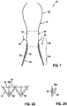
- a stent-valve 10 is illustrated for transcatheter implantation.
- the stent-valve 10 may be a cardiac stent-valve, for example, an aortic stent-valve, a mitral stent-valve, a pulmonary stent-valve or a tricuspid stent-valve, for implantation at the respective valve position in a human heart.
- the stent-valve 10 may optionally comprise biological tissue (for example, pericardium (such as porcine pericardium and/or bovine pericardium) and/or natural cardiac valve leaflets (for example, natural porcine cardiac valve leaflets, optionally attached to a portion of natural cardiac wall tissue).
- biological tissue for example, pericardium (such as porcine pericardium and/or bovine pericardium) and/or natural cardiac valve leaflets (for example, natural porcine cardiac valve leaflets, optionally attached to a portion of natural cardiac wall tissue).
- the biological tissue may be fixed, for example, using glutaraldehyde.
- the biological tissue may have anti-calcification properties, for example, having been treated or processed to inhibit or slow calcification (for example, by treatment in alcohol or a process using detergent).
- the stent-valve 10 may be compressible to a radially compressed condition (not shown) for delivery using a delivery catheter, and be expandable to an expanded condition (as shown) at implantation.
- the stent-valve 10 may comprise a stent 12 carrying a plurality of leaflets defining a valve 14.
- Various geometries of stent 12 may be used.
- the stent 12 may include one of more of: a lower tubular or crown portion 16; an upper crown portion 18; a plurality of upstanding commissural supports 20; and a plurality of stabilization arches 22.
- the lower portion 16 of the stent 12 may be configured to be deployed after the other regions of the stent 12 have first been at least partly deployed.
- the arches 22, the supports 20 and the upper crown 18 may be deployed at least partly before the lower portion 16 (in that order, or in reverse order, or in a different order).
- the stent 12 may be urged and/or displaced in the direction of arrow 24 to seat the upper crown 18 against native leaflets at the implantation site. Deploying the lower portion 16 last fixes the stent 12 in its final position.
- At least the lower portion 16, and optionally a portion of the upper crown 18, may be formed by a lattice structure of the stent.
- the lattice structure may define apertures, for example, generally diamond-shaped apertures.
- the upper crown 18 may be regarded as (e.g., being or comprising) a seal support, when a seal is attached to the upper crown 18.
- the seal support defined by the upper crown may be considered to deploy the seal at least somewhat outwardly relative to a portion or remainder of the stent just below the upper crown.
- the native leaflets may generally overlap a portion 26 of the stent.
- the native valve annulus may overlap a portion 28 of the stent.
- the stent-valve 10 further comprises an inner skirt 30 communicating with the leaflets 14 and carried on an interior of the stent 12. Additionally, the stent-valve 10 further comprises an outer skirt 32 carried on an exterior of the stent 12. When both skirts are provided, the skirts may partially overlap. The skirts may be offset such that one skirt (e.g. the outer skirt 32) extends further towards a lower extremity of the stent 12 than the other (e.g. inner skirt 30). Additionally or alternatively, one skirt (e.g. the inner skirt 30) extends further towards an upper extremity of the stent 12 than the other (e.g. outer skirt 32).
- the skirts may be of any suitable flexible and/or compliant material, for example, fabric (e.g. of PET), or of plastics film (e.g of PET), or of biological tissue (e.g. of pericardium).
- At least the outer skirt 32 is positioned to leave (e.g. at least a portion of) the upper crown 18 substantially unobscured by the outer skirt 32.
- Such an arrangement may assist good blood flow to the coronary arteries (for example, in the case of a stent-valve for the aortic valve).
- the lower portion 16 has an extremity formed with a substantially zig-zag shape.
- the zig-zag shape may comprise lower apexes 16a and upper apexes 16b.
- the upper apexes 16b may be masked in Fig. 1 by the superimposed presentation of both the frontmost and rearmost cells of the lattice structure.
- the zig-zag shape may be substantially continuous around the circumference of the stent 12.
- the outer skirt 32 may have a peripheral edge having a zig-zag shape that matches substantially the zig-zag shape of the extremity of the lower portion 16. Such an arrangement can avoid excessive material at the extremity, and thereby facilitate crimping of the stent-valve 10.
- the outer skirt 32 covers (for example, completely) open cells of the lattice structure down to the stent extremity to reduce risk of blood leakage through the apertures of the cells.
- the outer skirt 32 can also provide a layer of material over the struts of the stent, thereby to cushion the engagement between the stent and the sensitive native heart tissue.
- the valve 14 may comprise biological tissue, for example, pericardium (such as porcine pericardium or bovine pericardium) or natural cardiac valve leaflets (for example, natural porcine cardiac valve leaflets, optionally attached to a portion of natural cardiac wall tissue).
- pericardium such as porcine pericardium or bovine pericardium
- natural cardiac valve leaflets for example, natural porcine cardiac valve leaflets, optionally attached to a portion of natural cardiac wall tissue.
- Other biological or non-biological material could also be used for the valve 14, as desired.
- the stent 12 may optionally be of a self-expanding type that is compressible to the compressed state for loading into a delivery catheter having a sheath for constraining the stent 12 in the compressed state for delivery to the site of implantation. In use, by removal of the constraining effect of the sheath, the stent 12 self-expands to or (e.g. at least partly) towards the expanded state.
- a self-expanding stent may, for example, be of shape-memory material, for example, shape-memory metal alloy, for example, nitinol. Additionally or alternatively, the stent 12 may be configured to be expanded by application of an expanding force from the delivery catheter, such as by using an expansion balloon.
- seal configurations that may be used with the above-described stent-valve 10.
- the seal configurations may also be used with different stent shapes and configurations. Whether or not described in detail, the following descriptions of seals may use any single or multiple combination of, aforementioned stent and/or stent-valve features.
- Suitable materials for a seal may include biological tissue (for example, pericardium, such as porcine pericardium or bovine pericardium).
- biological tissue for example, pericardium, such as porcine pericardium or bovine pericardium.
- Biological tissue may be fixed tissue, for example, processed using glutaraldehyde.
- Pericardium is useful because of its very good flexibility, allowing the seal to conform to fit against and around the irregular shape of hard calcifications.
- suitable material for a seal may include plastics (for example, PET or PEEK). Plastics may be used in woven or non-woven fabric form, and/or in sheet form and/or film form, as desired. Plastics may combine toughness with suitable flexibility and conformability. The plastics may be of a biocompatible type.
- Fig. 2 illustrates a first example of seal support in the form of a plurality of cantilever elements 40 mounted on or integral with the stent 12.
- Each cantilever element 40 may be associated with a respective aperture 42 of the lattice structure.
- Each cantilever element 40 may be bendable generally independently of the others.
- Each cantilever element 40 may be movable between a stowed condition, in which the cantilever element is generally coplanar with the portion of the stent 12 around the aperture 42 (or at least is compressed to lie directly or indirectly thereagainst), and a deployed condition in which the cantilever element 40 is biased radially outwardly from the body (e.g. lower portion 16) of the stent 12 ( fig. 2b ).
- the seal support urges a seal (e.g. the outer skirt 32) outwardly so as to fill gaps or voids between the stent-valve 10 and the surrounding lumen/tissue.
- a seal e.g. the outer skirt 32
- the ability of the cantilever elements 40 to flex independently can provide a high degree of local conformity.
- Each cantilever element 40 may have a remote end 40a in the form of a rounded, or pad-like, or other non-damaging shape that can bear against the seal material to bias the seal radially outwardly, without penetrating through, or puncturing, the seal material.
- each cantilever element 40 may comprise a single strut.
- the cantilever elements 40 may be arranged generally in the same orientation (e.g. with the remote ends 40a directed towards one end, e.g. the outlet end, of the stent 12), or distributed to be orientated in two opposite directions, or be distributed to be orientated in a variety of different directions.
- the seal urged by the cantilever elements 40 may be generally continuous, or it may be discontinuous in the form of webs or pockets.
- the pockets may be arranged such that back-pressure of blood, of para-valvular blood flow in the reverse direction from outlet to inlet end of the stent 12, fills the pockets to cause the pockets further to distend, thereby enhancing the seal effect to obstruct such para-valvular flow. Further detail of such pockets is also described with reference to Fig. 13 , and any of such features may also be used with the present example.
- the seal may optionally be attached to the cantilever elements 40, or the seal may be unattached such that the cantilever elements 40 interact with the seal by pushing outwardly.
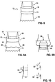
- a seal support 46 is illustrated in the form of an annular wire or ring that is oversize compared to the stent 10.
- the annular wire is compressible to a stowed state when the stent is compressed, and expands to a deployed state when unconstrained, to urge the seal 48 to a radially expanded state to form a seal against the surrounding tissue/lumen.
- a seal support 50 is illustrated in the form of an elongate member carrying a seal 52.
- the seal support is compressible to a stowed form ( Fig. 4a ) for example a helical shape around the stent 12 when in its compressed state.
- the seal support is expandable to a deployed state ( Fig. 4b ), for example, a radially expanded closed or semi-closed loop form in which the seal support presents the seal 52 in expanded form around the stent 12.
- a seal support 54 is illustrated in the form of an everting portion of the lower region 16 of the stent 12.
- the seal support 54 is movable between a stowed, non-everted configuration and a deployed, everted configuration.
- a sheath 56 Fig. 5a
- the lower portion of the stent including the seal support 54 is generally tubular (non-everted).
- the seal support 56 is unsheathed. Unconstrained, the seal support 56 everts to its deployed state in which the seal is presented and/or biased radially outwardly from the stent body.
- the everted seal support 54 urges the seal into tight sealing contact with the surrounding tissue/lumen.
- the seal may be carried on the inners surface of the stent when compressed, and presented in an outward direction when everted.
- Fig. 6 illustrates a seal support that is similar to both Figs. 2 and 5 .
- the seal support 58 comprises flexible cantilever elements at the lower portion 16 of the stent 12, similar to those of Fig. 2 .
- the seal support 58 also resembles the everted state of the seal support 56 of Fig. 5 .
- the cantilever elements do not move between an everted and non-everted state. In the stowed state, the cantilever elements are generally flat against or within the structure of the stent 12 (similar to Fig. 2 ).
- Fig. 7 illustrates a seal in the form of a rollable bead or cuff 60.
- the rollable cuff 60 may be self-biased or it may be supported by a seal support frame that tends to roll the cuff 60.
- a stowed state Fig. 7b
- the cuff In a stowed state ( Fig. 7b ), the cuff is unrolled to define a generally flat tubular form.
- the cuff may be constrained in the stowed state by a constraining sheath 62 of a delivery device.
- the cuff 60 When unsheathed, the cuff 60 is free to move to its deployed state ( Fig. 7a ) in which the cuff 60 rolls up to define a cuff or bead shape.
- Such a seal provides a compliant bead of material to fill any gap between the stent 12 and the surrounding tissue/lumen.
- Fig. 8 illustrates a seal 74 in the form of foam, or sponge or fibrous porous material.
- foam or sponge or fibrous porous material.
- Such material is compressible when dry, because air is easily expelled from the pores and/or interstices of material when compressed.
- the seal 74 may therefore adopt a compressed state without increasing the bulk of the stent-valve 10 significantly.
- blood Once implanted, blood may penetrate and fill the pores and/or interstices of the seal material.
- the blood may become trapped in the pores and/or interstices, thereby creating a barrier to blood flow through the material.
- the blood may also cause distension of the seal material to further expand the seal outwardly and fill any gaps of voids around the stent-valve 10.
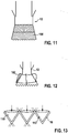
- Fig. 9 illustrates a seal in the form of a flexible skirt 80.
- the skirt 80 depends, for example, from the junction between the upper crown 18 and the lower portion 16 of the stent 16, to at least partly overlap the lower portion 16.
- a first (e.g. upper) portion 82 of the skirt 80 is coupled to the stent 12, to hold the skirt 80 captive.
- the first portion 82 may be sutured to the stent 12.
- a second (e.g. depending) portion 84 of the skirt 80 is generally unconstrained, and is free to float relative to the stent 12.
- the implantation procedure for the stent-valve 10 may involve displacing the stent-valve in the direction of arrow 24 to seat the upper crown 18 against native valve leaflets.
- the friction between the floating second portion 84 of the skirt 80, and the surrounding tissue/lumen may cause the second portion 84 to bunch or wrinkle axially, thus creating an excess of material that is able to seal any gap between the stent-valve 10 and the surrounding tissue/lumen.
- Fig. 10 illustrates an alternative seal in the form of a flexible skirt 90.
- the skirt 90 projects from the upper crown 18 towards the upper end of the stent 12.
- the flexible skirt bears outwardly to seal against the surrounding tissue/lumen.
- the flexible skirt may form a channel shape section such that the back pressure of blood increases the sealing pressure against the surrounding tissue/lumen.
- Fig. 11 illustrates an alternative seal in the form of an oversized flexible skirt 100 that is connected to the stent 12 at one or more positions to define pleating or bunching.
- the connections may be by suturing.
- the pleating or bunching creates additional compliant material able to fill vids of gaps between the stent 12 and the surrounding tissue/lumen.
- Fig. 12 illustrates an alternative seal in the form of a skirt that is folded to define a cuff 102.
- the skirt material is flexible, but the fold creates a radiused bend providing a natural bulge. The bulge biases the seal material outwardly in order to fill voids or gaps between between the stent 12 and the surrounding tissue/lumen.
- Fig. 13 illustrates an alternative seal comprising a plurality of flexible pockets 110.
- Each pocket may be associated with a respective aperture 112 of a lattice structure of the stent, for example, the lower portion 16 and/or the upper crown 18.
- the pocket 110 may be defined by a flexible web of material.
- One wall of the pocket may be defined by a portion of the outer skirt.
- Another wall of the pocket may be defined by a portion of the inner skirt.
- the pocket may be open on one side facing towards the outlet end of the stent, and closed in the opposite direction. In a stowed state, the pocket may collapse or fold substantially flat so as not to increase the bulk of the stent-valve.
- the pocket may open either under the influence of natural resilience, or under the influence of blood back pressure entering the mouth of the pocket.
- the back pressure causes the pocket to distend outwardly against surrounding tissue/lumen, and thereby further obstructing leakage of blood around the outside of the stent-valve 10.
- Fig. 14 illustrates an alternative seal arrangement comprising material 120 that swells in response to contact with blood.
- the swelling characteristics increase the bulk of the seal, enabling the seal to distend to fill any gaps between the stent-valve 10 and the surrounding tissue/lumen.
- Example swellable materials include a hydrogel and/or a liquid swellable polymer, and/or a so called superabsorbent material.
- the material may, for example, be carried by, or impregnated or otherwise embodied within the outer skirt.
- the skirt may be of fabric comprising fibres of the swellable material.
- the material may be captive within a containing chamber, for example a flexible and/or distensible pouch or cuff.
- the combination of inner and outer skirts, with one comprising swellable material can provide an especially effective seal arrangement. Further background information of use of, for example, a hydrogel for stent-valves may be found in US 2005/137688 .
- the seal of Fig. 14 is also illustrated in other embodiments of Figs. 18 and 19 .
- the swellable material is denoted by numeral 44, the containing chamber 42, together defining the paravalve seal 40 carried by, or comprised within, the outer skirt 32.
- Fig. 15 illustrates an alternative seal arrangement in which a sealant 122 is dispensed from the delivery catheter 124 (or from a further delivery catheter inserted after implantation), in order to seal around the periphery of the stent valve 10.
- the sealant is dispensed on the outflow side of the stent-valve to seal any gaps between the upper crown and the native leaflets.
- Fig. 16 illustrates an alternative seal arrangement comprising material 124 that provides haemostatic and/or coagulant effects in response to contact with blood.
- the material 124 may, for example, be carried by, or impregnated or otherwise embodied within the outer skirt.
- the material may be captive within a containing chamber, for example a flexible and/or distensible pouch or cuff.
- the combination of inner and outer skirts, with one comprising such material, can provide an especially effective seal arrangement.
- Fig. 17 illustrates an alternative seal arrangement comprising material 126 that elutes calcium locally.
- the calcium may deposit directly or indirectly against the surrounding tissue/lumen such that any gaps can be occluded.
- the material 126 may, for example, be carried by, or impregnated or otherwise embodied within the outer skirt.
- the material may be captive within a containing chamber, for example, a flexible and/or distensible pouch or cuff.
- the combination of inner and outer skirts, with one comprising such material, can provide an especially effective seal arrangement.
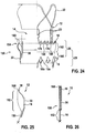
- Figs. 20-23 illustrate an alternative seal in the form of a flexible skirt 150.
- the skirt 150 may be the outer skirt 32 previously described.
- the skirt 150 is attached to the inner skirt 30 at least at one or more attachment positions 152 spaced from an end 154 of the skirt 150 closest to the outlet end 156 of the stent-valve 10.
- the one or more attachment positions 152 are such as to define a first skirt portion 160 captive with respect to the stent 12, and a second or further skirt portion 162 free to deploy or float relative to the stent 12.
- the one or more attachment positions 152 may, for example, correspond to an inlet end 164 of the stent-valve 10 and/or to an intermediate position between the extremities of the upper crown 18 and the lower portion 16.
- At least one attachment position 152 may overlap, at least partly, the inner skirt 30. At least one attachment position 152 forms a direct attachment between the (e.g. outer) seal skirt 150 and the inner skirt 30. Such attachment can obstruct leakage of blood between the skirts 30 and 150.
- the lower portion 16 has an extremity formed with a substantially zig-zag shape.
- the zig-zag shape may comprise lower apexes 16a and upper apexes 16b.
- the upper apexes 16b may be masked in Fig. 20 by the superimposed presentation of both the frontmost and rearmost cells of the lattice structure.
- the zig-zag shape may be substantially continuous around the circumference of the stent 12.
- the (e.g. outer) seal skirt 150 may have a peripheral edge having a zig-zag shape that matches substantially the zig-zag shape of the extremity of the lower portion 16.
- the (e.g. outer) seal skirt 150 covers (for example, completely) open cells of the lattice structure down to the stent extremity to reduce risk of blood leakage through the apertures of the cells.
- the (e.g. outer) seal skirt 150 can also provide a layer of material over the struts of the stent, thereby to cushion the engagement between the stent and the sensitive native heart tissue.
- the second portion 162 of the skirt 150 may define a pocket or flap that is able to distend outwardly under backpressure or backflow of blood.
- the flap or pocket may extend continuously over an angle of at least about 180 degrees, optionally at least about 270 degrees, optionally about 360 (e.g. correspond to entirely around the circumferential periphery).
- the flap or pocket may be substantially annular and/or channel shaped.
- the second portion 162 of the skirt distends against surrounding tissue, for example, under backpressure of blood acting on the stent-valve 10 when the valve 14 has closed, or para-valve leakage of blood backflowing around the stent-valve 10.
- Distention of the second skirt portion 162 may define a pocket, such that the backpressure of blood within the pocket effects a seal against the surrounding tissue.
- the second skirt portion 162 may function similarly to the skirt 90 of Fig. 10 , but positioned closer to the inlet end of the stent than in Fig. 10 .
- the skirt 150 may be dimensioned such that the end 154 closest to the outlet may be positioned axially at a desired position.
- the end 154 may be positioned to be substantially at a waist of the stent 12 between the extremities of the upper crown 18 and the lower portion 16.
- the end 154 may be positioned part way up the upper crown 18 (e.g. intermediate the waist and the extremity of the upper crown 18).
- the end 154 may be positioned substantially in register with the extremity of the upper crown 18.
- the end 154 may be positioned beyond the extremity of the upper crown 18 (e.g. extending at least partly beyond the upper crown 18 towards the outlet end of the stent-valve 10).
- the upper crown 18 may act as a seal support.
- the upper crown 18 may at least partly bias the second skirt portion 162 outwardly, for example with respect to the waist between the upper crown 18 and the lower portion 16. Such biasing may urge the second skirt portion 162 (i) into engagement with surrounding tissue and/or (ii) to a distended shape defining a flap or pocket responsive to blood back-pressure and/or blood back-flow around the exterior of the stent-valve 10.
- the upper crown 18 (and seal support) may comprise cantilever elements.
- the cantilever elements may be flexible independently of one another.
- Each cantilever element may have a U-shape or V-shape.
- Each cantilever element may comprise a pair of struts that meet at the apex of the cantilever element.
- the end 154 may have a substantially straight edge, or it may have a non-straight edge, for example, an undulating shape, or castellated shape, or notched shape.
- the variations in a non-straight edge may optionally align with apexes of the upper crown 18.
- Providing a non-straight edge may, in some embodiments, enable a reduction in the bulk of material of the skirt 150 to be compressed for loading on to or in to a delivery apparatus, which may be significant when the skirt 150 overlaps a region of the stent-valve 10 that is "crowded" in terms of stent material and/or leaflet material and/or skirt material to be compressed.
- the second skirt portion 162 may be wholly unattached to the stent 12.
- one or more control attachments 166 may be formed between the second skirt portion 162 and the stent 12 (for example, the upper crown 1'8).
- the control attachments 166 may be configured to permit the second skirt portion 162 to distend substantially freely, while preventing unwanted everting of the second skirt portion 162 (e.g. during compression and loading the stent-valve by an inexperienced user).
- Figs. 24-26 illustrate a further modification of the seal arrangement of Figs. 20-23 .
- the end 154 of the seal is attached to the upper crown 18 at plural positions 168 around the circumferential edges of the end 154, to define an annular pocket or annular channel shape of the second skirt portion 162.
- the second skirt portion 162 may distend or billow outwardly from the stent, as a distensible cuff, in response to backpressure and/or backflow of blood.
- the second skirt portion 162 may optionally have a clearance, and/or an aperture and/or a notch between adjacent positions 170, to define a communication port to allow blood to enter the annular pocket.
- the end 154 may have a castellated and/or notched and/or scalloped and/or undulating edge to define such communication ports.
- the upper crown 18 may act as a seal support.
- the attachment positions 168 may directly support the second skirt portion 162.
- the upper crown 18 may at least partly bias the second skirt portion 162 outwardly, for example with respect to the waist between the upper crown 18 and the lower portion 16. Such biasing may urge the second skirt portion 162 (i) into engagement with surrounding tissue and/or (ii) to a distended shape defining a flap or pocket responsive to blood back-pressure and/or blood back-flow around the exterior of the stent-valve 10.
- the upper crown 18 (and seal support) may comprise cantilever elements.
- the cantilever elements may be flexible independently of one another.
- Each cantilever element may have a U-shape or V-shape.
- Each cantilever element may comprise a pair of struts that meet at the apex of the cantilever element.
- Attachment of the end 154 to the upper crown may provide additional control over the otherwise free second skirt portion 162.
- Such an arrangement may facilitate, for example, compressing and loading of the stent-valve 10 for implantation, and avoid risk of the second skirt portion 162 being accidentally everted.
- the attachment positions 168 between the end 154 of the skirt 150 and the upper crown 18 may be chosen and/or varied as desired.
- the attachment positions 168 may correspond to the extremity of the upper crown 18.
- the attachment positions 168 may correspond to an intermediate position partway up the upper crown 18 (for example, intermediate the extremity of the upper crown 18, and the waist between the upper crown 18 and lower portion 16).
- Fig. 26 illustrates how the upper crown 18, and the skirt 150 of Fig. 25 , may be compressed to a stowed configuration when the stent-valve 10 is compressed using a loading apparatus (for example, a crimper or a compression funnel) for loading the stent-valve into or on to a delivery device (for example a delivery catheter, not shown).
- a loading apparatus for example, a crimper or a compression funnel
- the upper crown 18 and the second skirt portion 162 may lie substantially flat with the remainder of the stent 12.
- the upper crown 18 and the second skirt portion 162 may deploy radially outwardly (to the shape shown in Fig. 25 ).
- the skirt 150 may have any desired profile shape.
- the skirt 150 may have a substantially cylindrical shape.
- the diameter of the cylindrical shape may correspond to the maximum diameter of the lower portion 16 and/or to the diameter of the stent 12 (e.g. upper crown 18) at the point reached by the end 154 of the skirt 150, and/or the maximum diameter of the upper crown 18, and/or a dimension larger than the upper crown.
- the waist defined between the upper crown 18 and the lower portion 16, and/or the oversizing of a stent 12 with respect to the size of the native valve to be replaced typically about 1, 2 or 3 mm diameter oversizing
- the skirt 150 may be sculpted with a non-cylindrical shape, for example, a bulbous shape or a funnel shape, also to provide excess material able to distend or billow outwardly for the sealing effect.
- Suitable material may include biological tissue (for example, pericardium (for example, porcine pericardium or bovine pericardium). Additionally or alternatively, suitable material may include plastics (for example, PET or PEEK). Plastics may be used in woven or non-woven fabric form, and/or in sheet form, and/or in film form.
- biological tissue for example, pericardium (for example, porcine pericardium or bovine pericardium).
- suitable material may include plastics (for example, PET or PEEK). Plastics may be used in woven or non-woven fabric form, and/or in sheet form, and/or in film form.
Landscapes
- Health & Medical Sciences (AREA)
- Engineering & Computer Science (AREA)
- Biomedical Technology (AREA)
- Cardiology (AREA)
- Oral & Maxillofacial Surgery (AREA)
- Transplantation (AREA)
- Heart & Thoracic Surgery (AREA)
- Vascular Medicine (AREA)
- Life Sciences & Earth Sciences (AREA)
- Animal Behavior & Ethology (AREA)
- General Health & Medical Sciences (AREA)
- Public Health (AREA)
- Veterinary Medicine (AREA)
- Prostheses (AREA)
Claims (16)
- Valve endoprothétique pour implantation transcathéter pour remplacer une valvule cardiaque, la valve endoprothétique pouvant être comprimée à un état comprimé en vue de son introduction, et pouvant être expansée dans un état fonctionnel pour son implantation, la valve endoprothétique comprenant une endoprothèse (12), une pluralité de feuillets (14) pour définir une valve prothétique et un joint paravalve (40) pour réaliser un scellage vis-à-vis des tissus environnants, le joint comprenant une jupe (150), au moins une première portion (160) de laquelle étant captive par rapport à l'endoprothèse, et au moins une deuxième portion (162) de laquelle étant libre de se déployer ou de flotter par rapport à l'endoprothèse, la jupe étant une jupe extérieure (150) portée sur une partie extérieure de l'endoprothèse, et la valve endoprothétique présentant une extrémité d'entrée (164) et une extrémité de sortie (156),
la valve endoprothétique comprenant en outre une jupe intérieure (30) communiquant avec les feuillets et portée sur une partie intérieure de l'endoprothèse,
la jupe extérieure (150) étant fixée directement à la jupe intérieure (30) en une ou plusieurs positions de fixation (152) espacées d'une extrémité (154) de la jupe extérieure la plus proche de l'extrémité de sortie (156) de la valve endoprothétique, afin de bloquer une fuite de sang entre la jupe intérieure (30) et la jupe extérieure (150),
la première portion (160) de la jupe extérieure (150) s'étendant depuis la ou les positions de fixation (152) vers l'extrémité d'entrée (164) de la valve endoprothétique ; et
la deuxième portion (162) de la jupe extérieure (150) s'étendant depuis la ou les positions de fixation (152) jusqu'à l'extrémité (154) de la jupe extérieure la plus proche de l'extrémité de sortie (156) de la valve endoprothétique, la deuxième portion, pendant l'utilisation, pouvant être étirée vers l'extérieur afin de réaliser un scellage vis-à-vis des tissus environnants sous l'effet d'une contre-pression ou d'un reflux de sang. - Valve endoprothétique selon la revendication 1, dans laquelle les jupes intérieure et extérieure se chevauchent en partie, la jupe extérieure (150) s'étendant plus loin que la jupe intérieure (30) vers l'extrémité de l'endoprothèse au niveau de l'extrémité d'entrée (164) de la valve endoprothétique.
- Valve endoprothétique selon la revendication 1 ou 2, dans laquelle la jupe intérieure (30) s'étend plus loin que l'extérieur (150) vers l'extrémité de l'endoprothèse au niveau de l'extrémité de sortie (156) de la valve endoprothétique.
- Valve endoprothétique selon la revendication 1, 2 ou 3, dans laquelle la deuxième portion de la jupe extérieure est attachée à l'endoprothèse par une ou plusieurs fixations de contrôle (166) qui empêchent une éversion de la deuxième portion.
- Valve endoprothétique selon l'une quelconque des revendications 1 à 4, dans laquelle la deuxième portion (162) de la jupe extérieure définit une poche ou un rabat apte à s'étirer vers l'extérieur sous l'effet d'une contre-pression ou d'un reflux de sang.
- Valve endoprothétique selon l'une quelconque des revendications 1 à 5, dans laquelle les jupes intérieure et extérieure (30, 150) sont en matériau biologique.
- Valve endoprothétique selon l'une quelconque des revendications 1 à 6, dans laquelle les jupes intérieure et extérieure (30, 150) sont en tissu.
- Valve endoprothétique selon l'une quelconque des revendications 1 à 7, dans laquelle l'endoprothèse comprend : une portion tubulaire inférieure (16), une portion de couronne supérieure (18), une pluralité de supports commissuraux verticaux (20), et une pluralité d'arches de stabilisation (22).
- Valve endoprothétique selon la revendication 8, dans laquelle la portion tubulaire inférieure (16) communique avec la portion de couronne supérieure (18) et les supports commissuraux (20), les supports (20) commissuraux se dressant par rapport à la portion de couronne supérieure (18) et les arches de stabilisation (22) communiquant avec les supports commissuraux (20).
- Valve endoprothétique selon la revendication 8 ou 9, dans laquelle l'extrémité (154) de la jupe extérieure la plus proche de l'extrémité de sortie (156) de l'endoprothèse est positionnée au niveau d'un rétrécissement de l'endoprothèse entre les extrémités de la portion de couronne supérieure (18) et de la portion tubulaire inférieure (16).
- Valve endoprothétique selon la revendication 10, dans laquelle la jupe extérieure (150) descend de la jonction entre la portion de couronne supérieure (18) et la portion tubulaire inférieure (16).
- Valve endoprothétique selon les revendications 8 à 10, dans laquelle la portion de couronne supérieure sollicite au moins en partie la deuxième portion de jupe vers l'extérieur.
- Valve endoprothétique selon la revendication 12, dans laquelle la portion de couronne supérieure sollicite au moins en partie la deuxième portion vers l'extérieur par rapport à un rétrécissement entre la portion de couronne supérieure et la portion inférieure.
- Valve endoprothétique selon la revendication 12 ou 13, dans laquelle la couronne supérieure comprend des éléments en porte-à-faux, chaque élément en porte-à-faux comprenant une paire d'entretoises qui se rejoignent au sommet de l'élément en porte-à-faux.
- Valve endoprothétique selon l'une quelconque des revendications 8 à 11, dans laquelle la jupe extérieure (150) est positionnée de manière à laisser une portion de la couronne supérieure (18) sensiblement non obscurcie par la jupe extérieure.
- Valve endoprothétique selon la revendication 15, dans laquelle la jupe extérieure (150) est positionnée de manière à laisser la couronne supérieure (18) sensiblement non obscurcie par la jupe extérieure.
Priority Applications (3)
| Application Number | Priority Date | Filing Date | Title |
|---|---|---|---|
| EP17206171.5A EP3357456A1 (fr) | 2013-03-15 | 2013-03-25 | Améliorations apportées à des valves stents transcathéter |
| EP20187676.0A EP3777770A1 (fr) | 2013-03-15 | 2013-03-25 | Prothèse de valve transcathéter ayant une jupe externe pour assurer une étanchéité et prévenir les fuites paravalvulaires |
| EP19203816.4A EP3616652B1 (fr) | 2013-03-15 | 2013-03-25 | Améliorations apportées à des valves stents transcathéter |
Applications Claiming Priority (2)
| Application Number | Priority Date | Filing Date | Title |
|---|---|---|---|
| US13/839,357 US20130274873A1 (en) | 2012-03-22 | 2013-03-15 | Transcatheter Stent-Valves and Methods, Systems and Devices for Addressing Para-Valve Leakage |
| PCT/EP2013/000893 WO2014139545A1 (fr) | 2012-03-22 | 2013-03-25 | Améliorations associées à des endoprothèses-valvules transcathéters |
Related Child Applications (4)
| Application Number | Title | Priority Date | Filing Date |
|---|---|---|---|
| EP17206171.5A Division-Into EP3357456A1 (fr) | 2013-03-15 | 2013-03-25 | Améliorations apportées à des valves stents transcathéter |
| EP17206171.5A Division EP3357456A1 (fr) | 2013-03-15 | 2013-03-25 | Améliorations apportées à des valves stents transcathéter |
| EP20187676.0A Division EP3777770A1 (fr) | 2013-03-15 | 2013-03-25 | Prothèse de valve transcathéter ayant une jupe externe pour assurer une étanchéité et prévenir les fuites paravalvulaires |
| EP19203816.4A Division EP3616652B1 (fr) | 2013-03-15 | 2013-03-25 | Améliorations apportées à des valves stents transcathéter |
Publications (2)
| Publication Number | Publication Date |
|---|---|
| EP2967845A1 EP2967845A1 (fr) | 2016-01-20 |
| EP2967845B1 true EP2967845B1 (fr) | 2018-08-29 |
Family
ID=54261402
Family Applications (4)
| Application Number | Title | Priority Date | Filing Date |
|---|---|---|---|
| EP20187676.0A Pending EP3777770A1 (fr) | 2013-03-15 | 2013-03-25 | Prothèse de valve transcathéter ayant une jupe externe pour assurer une étanchéité et prévenir les fuites paravalvulaires |
| EP17206171.5A Pending EP3357456A1 (fr) | 2013-03-15 | 2013-03-25 | Améliorations apportées à des valves stents transcathéter |
| EP19203816.4A Active EP3616652B1 (fr) | 2013-03-15 | 2013-03-25 | Améliorations apportées à des valves stents transcathéter |
| EP13735192.0A Active EP2967845B1 (fr) | 2013-03-15 | 2013-03-25 | Améliorations associées à des valves endoprothetiques transcathéters |
Family Applications Before (3)
| Application Number | Title | Priority Date | Filing Date |
|---|---|---|---|
| EP20187676.0A Pending EP3777770A1 (fr) | 2013-03-15 | 2013-03-25 | Prothèse de valve transcathéter ayant une jupe externe pour assurer une étanchéité et prévenir les fuites paravalvulaires |
| EP17206171.5A Pending EP3357456A1 (fr) | 2013-03-15 | 2013-03-25 | Améliorations apportées à des valves stents transcathéter |
| EP19203816.4A Active EP3616652B1 (fr) | 2013-03-15 | 2013-03-25 | Améliorations apportées à des valves stents transcathéter |
Country Status (6)
| Country | Link |
|---|---|
| EP (4) | EP3777770A1 (fr) |
| JP (1) | JP6272915B2 (fr) |
| CN (2) | CN105188609B (fr) |
| AU (2) | AU2013382378B2 (fr) |
| BR (1) | BR112015022526B1 (fr) |
| CA (1) | CA2905544C (fr) |
Cited By (18)
| Publication number | Priority date | Publication date | Assignee | Title |
|---|---|---|---|---|
| US10856984B2 (en) | 2017-08-25 | 2020-12-08 | Neovasc Tiara Inc. | Sequentially deployed transcatheter mitral valve prosthesis |
| US10940001B2 (en) | 2012-05-30 | 2021-03-09 | Neovasc Tiara Inc. | Methods and apparatus for loading a prosthesis onto a delivery system |
| US11311376B2 (en) | 2019-06-20 | 2022-04-26 | Neovase Tiara Inc. | Low profile prosthetic mitral valve |
| US11357622B2 (en) | 2016-01-29 | 2022-06-14 | Neovase Tiara Inc. | Prosthetic valve for avoiding obstruction of outflow |
| US11389291B2 (en) | 2013-04-04 | 2022-07-19 | Neovase Tiara Inc. | Methods and apparatus for delivering a prosthetic valve to a beating heart |
| US11413139B2 (en) | 2011-11-23 | 2022-08-16 | Neovasc Tiara Inc. | Sequentially deployed transcatheter mitral valve prosthesis |
| US11419720B2 (en) | 2010-05-05 | 2022-08-23 | Neovasc Tiara Inc. | Transcatheter mitral valve prosthesis |
| US11464631B2 (en) | 2016-11-21 | 2022-10-11 | Neovasc Tiara Inc. | Methods and systems for rapid retraction of a transcatheter heart valve delivery system |
| US11491006B2 (en) | 2019-04-10 | 2022-11-08 | Neovasc Tiara Inc. | Prosthetic valve with natural blood flow |
| US11497602B2 (en) | 2012-02-14 | 2022-11-15 | Neovasc Tiara Inc. | Methods and apparatus for engaging a valve prosthesis with tissue |
| US11602429B2 (en) | 2019-04-01 | 2023-03-14 | Neovasc Tiara Inc. | Controllably deployable prosthetic valve |
| US11684474B2 (en) | 2018-01-25 | 2023-06-27 | Edwards Lifesciences Corporation | Delivery system for aided replacement valve recapture and repositioning post-deployment |
| US11737872B2 (en) | 2018-11-08 | 2023-08-29 | Neovasc Tiara Inc. | Ventricular deployment of a transcatheter mitral valve prosthesis |
| US11779742B2 (en) | 2019-05-20 | 2023-10-10 | Neovasc Tiara Inc. | Introducer with hemostasis mechanism |
| US11857441B2 (en) | 2018-09-04 | 2024-01-02 | 4C Medical Technologies, Inc. | Stent loading device |
| US11931253B2 (en) | 2020-01-31 | 2024-03-19 | 4C Medical Technologies, Inc. | Prosthetic heart valve delivery system: ball-slide attachment |
| US11944537B2 (en) | 2017-01-24 | 2024-04-02 | 4C Medical Technologies, Inc. | Systems, methods and devices for two-step delivery and implantation of prosthetic heart valve |
| US11957577B2 (en) | 2017-01-19 | 2024-04-16 | 4C Medical Technologies, Inc. | Systems, methods and devices for delivery systems, methods and devices for implanting prosthetic heart valves |
Families Citing this family (33)
| Publication number | Priority date | Publication date | Assignee | Title |
|---|---|---|---|---|
| US20130274873A1 (en) | 2012-03-22 | 2013-10-17 | Symetis Sa | Transcatheter Stent-Valves and Methods, Systems and Devices for Addressing Para-Valve Leakage |
| US11207176B2 (en) | 2012-03-22 | 2021-12-28 | Boston Scientific Scimed, Inc. | Transcatheter stent-valves and methods, systems and devices for addressing para-valve leakage |
| EP3777770A1 (fr) * | 2013-03-15 | 2021-02-17 | Symetis SA | Prothèse de valve transcathéter ayant une jupe externe pour assurer une étanchéité et prévenir les fuites paravalvulaires |
| US10973628B2 (en) * | 2017-08-18 | 2021-04-13 | Edwards Lifesciences Corporation | Pericardial sealing member for prosthetic heart valve |
| CN107411849B (zh) * | 2017-08-24 | 2018-11-30 | 北京航空航天大学 | 防瓣周漏经导管瓣膜系统及植入方法 |
| CN209474868U (zh) * | 2017-09-04 | 2019-10-11 | 杭州启明医疗器械股份有限公司 | 一种牵引索褶皱裙边的支架装置及心脏瓣膜 |
| US11147667B2 (en) * | 2017-09-08 | 2021-10-19 | Edwards Lifesciences Corporation | Sealing member for prosthetic heart valve |
| EP3723662A4 (fr) * | 2017-12-11 | 2021-09-29 | California Institute of Technology | Systèmes, dispositifs et procédés se rapportant à la fabrication de valvules prothétiques implantables de maniere intravasculaire |
| US10966821B2 (en) * | 2018-03-08 | 2021-04-06 | Symetis Sa | Heart valve sealing skirt with variable diameters |
| WO2019195860A2 (fr) | 2018-04-04 | 2019-10-10 | Vdyne, Llc | Dispositifs et procédés d'ancrage d'une valvule cardiaque transcathéter |
| AU2018424859B2 (en) * | 2018-05-23 | 2024-04-04 | Corcym S.R.L. | A cardiac valve prosthesis |
| US10595994B1 (en) | 2018-09-20 | 2020-03-24 | Vdyne, Llc | Side-delivered transcatheter heart valve replacement |
| US11071627B2 (en) | 2018-10-18 | 2021-07-27 | Vdyne, Inc. | Orthogonally delivered transcatheter heart valve frame for valve in valve prosthesis |
| US11278437B2 (en) | 2018-12-08 | 2022-03-22 | Vdyne, Inc. | Compression capable annular frames for side delivery of transcatheter heart valve replacement |
| US10321995B1 (en) | 2018-09-20 | 2019-06-18 | Vdyne, Llc | Orthogonally delivered transcatheter heart valve replacement |
| US11344413B2 (en) | 2018-09-20 | 2022-05-31 | Vdyne, Inc. | Transcatheter deliverable prosthetic heart valves and methods of delivery |
| US11109969B2 (en) | 2018-10-22 | 2021-09-07 | Vdyne, Inc. | Guidewire delivery of transcatheter heart valve |
| DE102018126828A1 (de) * | 2018-10-26 | 2020-04-30 | Nvt Ag | Herzklappenprothese |
| US11253359B2 (en) | 2018-12-20 | 2022-02-22 | Vdyne, Inc. | Proximal tab for side-delivered transcatheter heart valves and methods of delivery |
| US11185409B2 (en) | 2019-01-26 | 2021-11-30 | Vdyne, Inc. | Collapsible inner flow control component for side-delivered transcatheter heart valve prosthesis |
| US11273032B2 (en) | 2019-01-26 | 2022-03-15 | Vdyne, Inc. | Collapsible inner flow control component for side-deliverable transcatheter heart valve prosthesis |
| CA3132162A1 (fr) | 2019-03-05 | 2020-09-10 | Vdyne, Inc. | Dispositifs de regulation de regurgitation tricuspide pour prothese de valvule cardiaque transcatheter orthogonale |
| US11076956B2 (en) | 2019-03-14 | 2021-08-03 | Vdyne, Inc. | Proximal, distal, and anterior anchoring tabs for side-delivered transcatheter mitral valve prosthesis |
| US11173027B2 (en) | 2019-03-14 | 2021-11-16 | Vdyne, Inc. | Side-deliverable transcatheter prosthetic valves and methods for delivering and anchoring the same |
| JP2022519928A (ja) * | 2019-03-27 | 2022-03-25 | エドワーズ ライフサイエンシーズ コーポレイション | 人工心臓弁のための封止部材 |
| EP3965701A4 (fr) | 2019-05-04 | 2023-02-15 | Vdyne, Inc. | Dispositif cinch et procédé de déploiement d'une valvule cardiaque prothétique à pose latérale dans un anneau natif |
| AU2020334080A1 (en) | 2019-08-20 | 2022-03-24 | Vdyne, Inc. | Delivery and retrieval devices and methods for side-deliverable transcatheter prosthetic valves |
| CN114630665A (zh) | 2019-08-26 | 2022-06-14 | 维迪内股份有限公司 | 可侧面输送的经导管假体瓣膜及其输送和锚定方法 |
| CN113081386B (zh) * | 2019-12-23 | 2023-09-19 | 先健科技(深圳)有限公司 | 覆膜支架 |
| US11234813B2 (en) | 2020-01-17 | 2022-02-01 | Vdyne, Inc. | Ventricular stability elements for side-deliverable prosthetic heart valves and methods of delivery |
| CN113768660A (zh) * | 2020-06-10 | 2021-12-10 | 先健科技(深圳)有限公司 | 人工心脏瓣膜和人工心脏瓣膜系统 |
| WO2022236929A1 (fr) * | 2021-05-14 | 2022-11-17 | 上海臻亿医疗科技有限公司 | Appareil de prothèse de valve cardiaque |
| CN117224278B (zh) * | 2023-11-10 | 2024-02-27 | 广东脉搏医疗科技有限公司 | 管腔流量调节器及冠状窦缩窄装置 |
Citations (2)
| Publication number | Priority date | Publication date | Assignee | Title |
|---|---|---|---|---|
| US20050137688A1 (en) * | 2003-12-23 | 2005-06-23 | Sadra Medical, A Delaware Corporation | Repositionable heart valve and method |
| WO2012048035A2 (fr) * | 2010-10-05 | 2012-04-12 | Edwards Lifesciences Corporation | Valve cardiaque prosthétique |
Family Cites Families (24)
| Publication number | Priority date | Publication date | Assignee | Title |
|---|---|---|---|---|
| US8579966B2 (en) * | 1999-11-17 | 2013-11-12 | Medtronic Corevalve Llc | Prosthetic valve for transluminal delivery |
| FR2815844B1 (fr) | 2000-10-31 | 2003-01-17 | Jacques Seguin | Support tubulaire de mise en place, par voie percutanee, d'une valve cardiaque de remplacement |
| US8052749B2 (en) * | 2003-12-23 | 2011-11-08 | Sadra Medical, Inc. | Methods and apparatus for endovascular heart valve replacement comprising tissue grasping elements |
| US20070073387A1 (en) * | 2004-02-27 | 2007-03-29 | Forster David C | Prosthetic Heart Valves, Support Structures And Systems And Methods For Implanting The Same |
| US7276078B2 (en) * | 2004-06-30 | 2007-10-02 | Edwards Lifesciences Pvt | Paravalvular leak detection, sealing, and prevention |
| US20070179600A1 (en) * | 2004-10-04 | 2007-08-02 | Gil Vardi | Stent graft including expandable cuff |
| US7914569B2 (en) * | 2005-05-13 | 2011-03-29 | Medtronics Corevalve Llc | Heart valve prosthesis and methods of manufacture and use |
| CA2607744C (fr) * | 2005-05-24 | 2015-11-24 | Edwards Lifesciences Corporation | Prothese de valvule cardiaque a deploiement rapide |
| CN100584292C (zh) * | 2005-11-09 | 2010-01-27 | 温宁 | 人工心脏支架瓣膜 |
| US20070118210A1 (en) * | 2005-11-18 | 2007-05-24 | Leonard Pinchuk | Trileaflet Heart Valve |
| US8834564B2 (en) * | 2006-09-19 | 2014-09-16 | Medtronic, Inc. | Sinus-engaging valve fixation member |
| WO2009024859A2 (fr) * | 2007-08-21 | 2009-02-26 | Symetis Sa | Endoprothèses valvulaires pour un remplacement de valvule et procédés associés et systèmes pour une chirurgie |
| US9848981B2 (en) * | 2007-10-12 | 2017-12-26 | Mayo Foundation For Medical Education And Research | Expandable valve prosthesis with sealing mechanism |
| DE202009018962U1 (de) * | 2008-07-15 | 2014-11-26 | St. Jude Medical, Inc. | Manschette zur Verwendung in einer Herzklappenprothese |
| RU140821U1 (ru) * | 2009-11-02 | 2014-05-20 | Симетис Са | Аортальный биопротез и системы для его доставки в место имплантации |
| US8449599B2 (en) | 2009-12-04 | 2013-05-28 | Edwards Lifesciences Corporation | Prosthetic valve for replacing mitral valve |
| US9545306B2 (en) | 2010-04-21 | 2017-01-17 | Medtronic, Inc. | Prosthetic valve with sealing members and methods of use thereof |
| CN106073946B (zh) * | 2010-09-10 | 2022-01-04 | 西美蒂斯股份公司 | 瓣膜置换装置、用于瓣膜置换装置的递送装置以及瓣膜置换装置的生产方法 |
| CN103997990A (zh) | 2011-06-21 | 2014-08-20 | 托尔福公司 | 人工心脏瓣膜装置及相关系统和方法 |
| CA3082787C (fr) * | 2011-12-06 | 2021-03-09 | Aortic Innovations Llc | Dispositif pour une reparation aortique endovasculaire et procede d'utilisation du dispositif |
| US20130274873A1 (en) | 2012-03-22 | 2013-10-17 | Symetis Sa | Transcatheter Stent-Valves and Methods, Systems and Devices for Addressing Para-Valve Leakage |
| US9636222B2 (en) | 2013-03-12 | 2017-05-02 | St. Jude Medical, Cardiology Division, Inc. | Paravalvular leak protection |
| US9326856B2 (en) | 2013-03-14 | 2016-05-03 | St. Jude Medical, Cardiology Division, Inc. | Cuff configurations for prosthetic heart valve |
| EP3777770A1 (fr) * | 2013-03-15 | 2021-02-17 | Symetis SA | Prothèse de valve transcathéter ayant une jupe externe pour assurer une étanchéité et prévenir les fuites paravalvulaires |
-
2013
- 2013-03-25 EP EP20187676.0A patent/EP3777770A1/fr active Pending
- 2013-03-25 EP EP17206171.5A patent/EP3357456A1/fr active Pending
- 2013-03-25 EP EP19203816.4A patent/EP3616652B1/fr active Active
- 2013-03-25 AU AU2013382378A patent/AU2013382378B2/en active Active
- 2013-03-25 CN CN201380074734.8A patent/CN105188609B/zh active Active
- 2013-03-25 EP EP13735192.0A patent/EP2967845B1/fr active Active
- 2013-03-25 BR BR112015022526-8A patent/BR112015022526B1/pt active IP Right Grant
- 2013-03-25 CA CA2905544A patent/CA2905544C/fr active Active
- 2013-03-25 CN CN201710957914.0A patent/CN107714240B/zh active Active
- 2013-03-25 JP JP2015561945A patent/JP6272915B2/ja active Active
-
2018
- 2018-05-01 AU AU2018203018A patent/AU2018203018B2/en active Active
Patent Citations (2)
| Publication number | Priority date | Publication date | Assignee | Title |
|---|---|---|---|---|
| US20050137688A1 (en) * | 2003-12-23 | 2005-06-23 | Sadra Medical, A Delaware Corporation | Repositionable heart valve and method |
| WO2012048035A2 (fr) * | 2010-10-05 | 2012-04-12 | Edwards Lifesciences Corporation | Valve cardiaque prosthétique |
Cited By (22)
| Publication number | Priority date | Publication date | Assignee | Title |
|---|---|---|---|---|
| US11419720B2 (en) | 2010-05-05 | 2022-08-23 | Neovasc Tiara Inc. | Transcatheter mitral valve prosthesis |
| US11413139B2 (en) | 2011-11-23 | 2022-08-16 | Neovasc Tiara Inc. | Sequentially deployed transcatheter mitral valve prosthesis |
| US11497602B2 (en) | 2012-02-14 | 2022-11-15 | Neovasc Tiara Inc. | Methods and apparatus for engaging a valve prosthesis with tissue |
| US11389294B2 (en) | 2012-05-30 | 2022-07-19 | Neovasc Tiara Inc. | Methods and apparatus for loading a prosthesis onto a delivery system |
| US11617650B2 (en) | 2012-05-30 | 2023-04-04 | Neovasc Tiara Inc. | Methods and apparatus for loading a prosthesis onto a delivery system |
| US10940001B2 (en) | 2012-05-30 | 2021-03-09 | Neovasc Tiara Inc. | Methods and apparatus for loading a prosthesis onto a delivery system |
| US11389291B2 (en) | 2013-04-04 | 2022-07-19 | Neovase Tiara Inc. | Methods and apparatus for delivering a prosthetic valve to a beating heart |
| US11357622B2 (en) | 2016-01-29 | 2022-06-14 | Neovase Tiara Inc. | Prosthetic valve for avoiding obstruction of outflow |
| US11464631B2 (en) | 2016-11-21 | 2022-10-11 | Neovasc Tiara Inc. | Methods and systems for rapid retraction of a transcatheter heart valve delivery system |
| US11957577B2 (en) | 2017-01-19 | 2024-04-16 | 4C Medical Technologies, Inc. | Systems, methods and devices for delivery systems, methods and devices for implanting prosthetic heart valves |
| US11944537B2 (en) | 2017-01-24 | 2024-04-02 | 4C Medical Technologies, Inc. | Systems, methods and devices for two-step delivery and implantation of prosthetic heart valve |
| US10856984B2 (en) | 2017-08-25 | 2020-12-08 | Neovasc Tiara Inc. | Sequentially deployed transcatheter mitral valve prosthesis |
| US11793640B2 (en) | 2017-08-25 | 2023-10-24 | Neovasc Tiara Inc. | Sequentially deployed transcatheter mitral valve prosthesis |
| US11684474B2 (en) | 2018-01-25 | 2023-06-27 | Edwards Lifesciences Corporation | Delivery system for aided replacement valve recapture and repositioning post-deployment |
| US11857441B2 (en) | 2018-09-04 | 2024-01-02 | 4C Medical Technologies, Inc. | Stent loading device |
| US11737872B2 (en) | 2018-11-08 | 2023-08-29 | Neovasc Tiara Inc. | Ventricular deployment of a transcatheter mitral valve prosthesis |
| US11602429B2 (en) | 2019-04-01 | 2023-03-14 | Neovasc Tiara Inc. | Controllably deployable prosthetic valve |
| US11491006B2 (en) | 2019-04-10 | 2022-11-08 | Neovasc Tiara Inc. | Prosthetic valve with natural blood flow |
| US11779742B2 (en) | 2019-05-20 | 2023-10-10 | Neovasc Tiara Inc. | Introducer with hemostasis mechanism |
| US11931254B2 (en) | 2019-06-20 | 2024-03-19 | Neovasc Tiara Inc. | Low profile prosthetic mitral valve |
| US11311376B2 (en) | 2019-06-20 | 2022-04-26 | Neovase Tiara Inc. | Low profile prosthetic mitral valve |
| US11931253B2 (en) | 2020-01-31 | 2024-03-19 | 4C Medical Technologies, Inc. | Prosthetic heart valve delivery system: ball-slide attachment |
Also Published As
| Publication number | Publication date |
|---|---|
| AU2013382378A1 (en) | 2015-10-08 |
| AU2013382378B2 (en) | 2018-03-15 |
| CN105188609B (zh) | 2017-11-10 |
| CA2905544A1 (fr) | 2014-09-18 |
| CA2905544C (fr) | 2020-08-18 |
| JP2016509891A (ja) | 2016-04-04 |
| CN105188609A (zh) | 2015-12-23 |
| EP3357456A1 (fr) | 2018-08-08 |
| BR112015022526A2 (pt) | 2017-07-18 |
| AU2018203018A1 (en) | 2018-05-17 |
| AU2018203018B2 (en) | 2019-03-28 |
| CN107714240B (zh) | 2021-04-02 |
| CN107714240A (zh) | 2018-02-23 |
| BR112015022526B1 (pt) | 2020-12-15 |
| EP3616652B1 (fr) | 2020-07-29 |
| EP3616652A1 (fr) | 2020-03-04 |
| EP3777770A1 (fr) | 2021-02-17 |
| EP2967845A1 (fr) | 2016-01-20 |
| JP6272915B2 (ja) | 2018-01-31 |
Similar Documents
| Publication | Publication Date | Title |
|---|---|---|
| US10898321B2 (en) | Transcatheter stent-valves | |
| AU2018203018B2 (en) | Improvements relating to transcatheter stent-valves | |
| US11207176B2 (en) | Transcatheter stent-valves and methods, systems and devices for addressing para-valve leakage | |
| US11833039B2 (en) | Leaflet suturing to commissure points for prosthetic heart valve | |
| US20220354640A1 (en) | Stent Assembly For Use in Prosthetic Heart Valves | |
| CN111050700B (zh) | 用于人工心脏瓣膜的密封构件 | |
| AU2014264335B2 (en) | System and method for sealing percutaneous valve | |
| US20140350665A1 (en) | Collapsible and re-expandable prosthetic heart valve cuff designs and complementary technological applications | |
| CN114144145A (zh) | 经导管心脏瓣膜递送系统和方法 | |
| JP2018094430A (ja) | 経カテーテルステント弁に関する改良 | |
| US20240008977A1 (en) | Prosthetic heart valve having elongated sealing member |
Legal Events
| Date | Code | Title | Description |
|---|---|---|---|
| PUAI | Public reference made under article 153(3) epc to a published international application that has entered the european phase |
Free format text: ORIGINAL CODE: 0009012 |
|
| 17P | Request for examination filed |
Effective date: 20150911 |
|
| AK | Designated contracting states |
Kind code of ref document: A1 Designated state(s): AL AT BE BG CH CY CZ DE DK EE ES FI FR GB GR HR HU IE IS IT LI LT LU LV MC MK MT NL NO PL PT RO RS SE SI SK SM TR |
|
| AX | Request for extension of the european patent |
Extension state: BA ME |
|
| DAX | Request for extension of the european patent (deleted) | ||
| STAA | Information on the status of an ep patent application or granted ep patent |
Free format text: STATUS: EXAMINATION IS IN PROGRESS |
|
| 17Q | First examination report despatched |
Effective date: 20161221 |
|
| GRAP | Despatch of communication of intention to grant a patent |
Free format text: ORIGINAL CODE: EPIDOSNIGR1 |
|
| STAA | Information on the status of an ep patent application or granted ep patent |
Free format text: STATUS: GRANT OF PATENT IS INTENDED |
|
| INTG | Intention to grant announced |
Effective date: 20180416 |
|
| GRAJ | Information related to disapproval of communication of intention to grant by the applicant or resumption of examination proceedings by the epo deleted |
Free format text: ORIGINAL CODE: EPIDOSDIGR1 |
|
| STAA | Information on the status of an ep patent application or granted ep patent |
Free format text: STATUS: EXAMINATION IS IN PROGRESS |
|
| GRAR | Information related to intention to grant a patent recorded |
Free format text: ORIGINAL CODE: EPIDOSNIGR71 |
|
| GRAS | Grant fee paid |
Free format text: ORIGINAL CODE: EPIDOSNIGR3 |
|
| STAA | Information on the status of an ep patent application or granted ep patent |
Free format text: STATUS: GRANT OF PATENT IS INTENDED |
|
| GRAA | (expected) grant |
Free format text: ORIGINAL CODE: 0009210 |
|
| STAA | Information on the status of an ep patent application or granted ep patent |
Free format text: STATUS: THE PATENT HAS BEEN GRANTED |
|
| INTC | Intention to grant announced (deleted) | ||
| AK | Designated contracting states |
Kind code of ref document: B1 Designated state(s): AL AT BE BG CH CY CZ DE DK EE ES FI FR GB GR HR HU IE IS IT LI LT LU LV MC MK MT NL NO PL PT RO RS SE SI SK SM TR |
|
| INTG | Intention to grant announced |
Effective date: 20180723 |
|
| REG | Reference to a national code |
Ref country code: GB Ref legal event code: FG4D |
|
| REG | Reference to a national code |
Ref country code: CH Ref legal event code: EP |
|
| REG | Reference to a national code |
Ref country code: AT Ref legal event code: REF Ref document number: 1034256 Country of ref document: AT Kind code of ref document: T Effective date: 20180915 |
|
| REG | Reference to a national code |
Ref country code: IE Ref legal event code: FG4D |
|
| REG | Reference to a national code |
Ref country code: DE Ref legal event code: R096 Ref document number: 602013042751 Country of ref document: DE |
|
| REG | Reference to a national code |
Ref country code: NL Ref legal event code: FP |
|
| REG | Reference to a national code |
Ref country code: LT Ref legal event code: MG4D |
|
| PG25 | Lapsed in a contracting state [announced via postgrant information from national office to epo] |
Ref country code: NO Free format text: LAPSE BECAUSE OF FAILURE TO SUBMIT A TRANSLATION OF THE DESCRIPTION OR TO PAY THE FEE WITHIN THE PRESCRIBED TIME-LIMIT Effective date: 20181129 Ref country code: BG Free format text: LAPSE BECAUSE OF FAILURE TO SUBMIT A TRANSLATION OF THE DESCRIPTION OR TO PAY THE FEE WITHIN THE PRESCRIBED TIME-LIMIT Effective date: 20181129 Ref country code: LT Free format text: LAPSE BECAUSE OF FAILURE TO SUBMIT A TRANSLATION OF THE DESCRIPTION OR TO PAY THE FEE WITHIN THE PRESCRIBED TIME-LIMIT Effective date: 20180829 Ref country code: IS Free format text: LAPSE BECAUSE OF FAILURE TO SUBMIT A TRANSLATION OF THE DESCRIPTION OR TO PAY THE FEE WITHIN THE PRESCRIBED TIME-LIMIT Effective date: 20181229 Ref country code: GR Free format text: LAPSE BECAUSE OF FAILURE TO SUBMIT A TRANSLATION OF THE DESCRIPTION OR TO PAY THE FEE WITHIN THE PRESCRIBED TIME-LIMIT Effective date: 20181130 Ref country code: FI Free format text: LAPSE BECAUSE OF FAILURE TO SUBMIT A TRANSLATION OF THE DESCRIPTION OR TO PAY THE FEE WITHIN THE PRESCRIBED TIME-LIMIT Effective date: 20180829 Ref country code: RS Free format text: LAPSE BECAUSE OF FAILURE TO SUBMIT A TRANSLATION OF THE DESCRIPTION OR TO PAY THE FEE WITHIN THE PRESCRIBED TIME-LIMIT Effective date: 20180829 Ref country code: SE Free format text: LAPSE BECAUSE OF FAILURE TO SUBMIT A TRANSLATION OF THE DESCRIPTION OR TO PAY THE FEE WITHIN THE PRESCRIBED TIME-LIMIT Effective date: 20180829 |
|
| REG | Reference to a national code |
Ref country code: AT Ref legal event code: MK05 Ref document number: 1034256 Country of ref document: AT Kind code of ref document: T Effective date: 20180829 |
|
| PG25 | Lapsed in a contracting state [announced via postgrant information from national office to epo] |
Ref country code: AL Free format text: LAPSE BECAUSE OF FAILURE TO SUBMIT A TRANSLATION OF THE DESCRIPTION OR TO PAY THE FEE WITHIN THE PRESCRIBED TIME-LIMIT Effective date: 20180829 Ref country code: HR Free format text: LAPSE BECAUSE OF FAILURE TO SUBMIT A TRANSLATION OF THE DESCRIPTION OR TO PAY THE FEE WITHIN THE PRESCRIBED TIME-LIMIT Effective date: 20180829 Ref country code: LV Free format text: LAPSE BECAUSE OF FAILURE TO SUBMIT A TRANSLATION OF THE DESCRIPTION OR TO PAY THE FEE WITHIN THE PRESCRIBED TIME-LIMIT Effective date: 20180829 |
|
| PG25 | Lapsed in a contracting state [announced via postgrant information from national office to epo] |
Ref country code: AT Free format text: LAPSE BECAUSE OF FAILURE TO SUBMIT A TRANSLATION OF THE DESCRIPTION OR TO PAY THE FEE WITHIN THE PRESCRIBED TIME-LIMIT Effective date: 20180829 Ref country code: EE Free format text: LAPSE BECAUSE OF FAILURE TO SUBMIT A TRANSLATION OF THE DESCRIPTION OR TO PAY THE FEE WITHIN THE PRESCRIBED TIME-LIMIT Effective date: 20180829 Ref country code: PL Free format text: LAPSE BECAUSE OF FAILURE TO SUBMIT A TRANSLATION OF THE DESCRIPTION OR TO PAY THE FEE WITHIN THE PRESCRIBED TIME-LIMIT Effective date: 20180829 Ref country code: CZ Free format text: LAPSE BECAUSE OF FAILURE TO SUBMIT A TRANSLATION OF THE DESCRIPTION OR TO PAY THE FEE WITHIN THE PRESCRIBED TIME-LIMIT Effective date: 20180829 Ref country code: IT Free format text: LAPSE BECAUSE OF FAILURE TO SUBMIT A TRANSLATION OF THE DESCRIPTION OR TO PAY THE FEE WITHIN THE PRESCRIBED TIME-LIMIT Effective date: 20180829 Ref country code: ES Free format text: LAPSE BECAUSE OF FAILURE TO SUBMIT A TRANSLATION OF THE DESCRIPTION OR TO PAY THE FEE WITHIN THE PRESCRIBED TIME-LIMIT Effective date: 20180829 Ref country code: RO Free format text: LAPSE BECAUSE OF FAILURE TO SUBMIT A TRANSLATION OF THE DESCRIPTION OR TO PAY THE FEE WITHIN THE PRESCRIBED TIME-LIMIT Effective date: 20180829 |
|
| PG25 | Lapsed in a contracting state [announced via postgrant information from national office to epo] |
Ref country code: SM Free format text: LAPSE BECAUSE OF FAILURE TO SUBMIT A TRANSLATION OF THE DESCRIPTION OR TO PAY THE FEE WITHIN THE PRESCRIBED TIME-LIMIT Effective date: 20180829 Ref country code: DK Free format text: LAPSE BECAUSE OF FAILURE TO SUBMIT A TRANSLATION OF THE DESCRIPTION OR TO PAY THE FEE WITHIN THE PRESCRIBED TIME-LIMIT Effective date: 20180829 Ref country code: SK Free format text: LAPSE BECAUSE OF FAILURE TO SUBMIT A TRANSLATION OF THE DESCRIPTION OR TO PAY THE FEE WITHIN THE PRESCRIBED TIME-LIMIT Effective date: 20180829 |
|
| REG | Reference to a national code |
Ref country code: DE Ref legal event code: R097 Ref document number: 602013042751 Country of ref document: DE |
|
| PLBE | No opposition filed within time limit |
Free format text: ORIGINAL CODE: 0009261 |
|
| STAA | Information on the status of an ep patent application or granted ep patent |
Free format text: STATUS: NO OPPOSITION FILED WITHIN TIME LIMIT |
|
| 26N | No opposition filed |
Effective date: 20190531 |
|
| PG25 | Lapsed in a contracting state [announced via postgrant information from national office to epo] |
Ref country code: SI Free format text: LAPSE BECAUSE OF FAILURE TO SUBMIT A TRANSLATION OF THE DESCRIPTION OR TO PAY THE FEE WITHIN THE PRESCRIBED TIME-LIMIT Effective date: 20180829 |
|
| PG25 | Lapsed in a contracting state [announced via postgrant information from national office to epo] |
Ref country code: MC Free format text: LAPSE BECAUSE OF FAILURE TO SUBMIT A TRANSLATION OF THE DESCRIPTION OR TO PAY THE FEE WITHIN THE PRESCRIBED TIME-LIMIT Effective date: 20180829 |
|
| PG25 | Lapsed in a contracting state [announced via postgrant information from national office to epo] |
Ref country code: LU Free format text: LAPSE BECAUSE OF NON-PAYMENT OF DUE FEES Effective date: 20190325 |
|
| REG | Reference to a national code |
Ref country code: BE Ref legal event code: MM Effective date: 20190331 |
|
| PG25 | Lapsed in a contracting state [announced via postgrant information from national office to epo] |
Ref country code: BE Free format text: LAPSE BECAUSE OF NON-PAYMENT OF DUE FEES Effective date: 20190331 |
|
| PG25 | Lapsed in a contracting state [announced via postgrant information from national office to epo] |
Ref country code: TR Free format text: LAPSE BECAUSE OF FAILURE TO SUBMIT A TRANSLATION OF THE DESCRIPTION OR TO PAY THE FEE WITHIN THE PRESCRIBED TIME-LIMIT Effective date: 20180829 |
|
| PG25 | Lapsed in a contracting state [announced via postgrant information from national office to epo] |
Ref country code: MT Free format text: LAPSE BECAUSE OF NON-PAYMENT OF DUE FEES Effective date: 20190325 Ref country code: PT Free format text: LAPSE BECAUSE OF FAILURE TO SUBMIT A TRANSLATION OF THE DESCRIPTION OR TO PAY THE FEE WITHIN THE PRESCRIBED TIME-LIMIT Effective date: 20181229 |
|
| PG25 | Lapsed in a contracting state [announced via postgrant information from national office to epo] |
Ref country code: CY Free format text: LAPSE BECAUSE OF FAILURE TO SUBMIT A TRANSLATION OF THE DESCRIPTION OR TO PAY THE FEE WITHIN THE PRESCRIBED TIME-LIMIT Effective date: 20180829 |
|
| PG25 | Lapsed in a contracting state [announced via postgrant information from national office to epo] |
Ref country code: HU Free format text: LAPSE BECAUSE OF FAILURE TO SUBMIT A TRANSLATION OF THE DESCRIPTION OR TO PAY THE FEE WITHIN THE PRESCRIBED TIME-LIMIT; INVALID AB INITIO Effective date: 20130325 |
|
| REG | Reference to a national code |
Ref country code: DE Ref legal event code: R081 Ref document number: 602013042751 Country of ref document: DE Owner name: BOSTON SCIENTIFIC MEDICAL DEVICE LIMITED, IE Free format text: FORMER OWNER: SYMETIS SA, ECUBLENS, CH |
|
| REG | Reference to a national code |
Ref country code: GB Ref legal event code: 732E Free format text: REGISTERED BETWEEN 20211216 AND 20211222 |
|
| REG | Reference to a national code |
Ref country code: GB Ref legal event code: 732E Free format text: REGISTERED BETWEEN 20211223 AND 20211229 |
|
| REG | Reference to a national code |
Ref country code: NL Ref legal event code: PD Owner name: BOSTON SCIENTIFIC MEDICAL DEVICE LIMITED; IE Free format text: DETAILS ASSIGNMENT: CHANGE OF OWNER(S), ASSIGNMENT; FORMER OWNER NAME: SYMETIS SA Effective date: 20220527 |
|
| PG25 | Lapsed in a contracting state [announced via postgrant information from national office to epo] |
Ref country code: MK Free format text: LAPSE BECAUSE OF FAILURE TO SUBMIT A TRANSLATION OF THE DESCRIPTION OR TO PAY THE FEE WITHIN THE PRESCRIBED TIME-LIMIT Effective date: 20180829 |
|
| PGFP | Annual fee paid to national office [announced via postgrant information from national office to epo] |
Ref country code: IE Payment date: 20230222 Year of fee payment: 11 Ref country code: FR Payment date: 20230222 Year of fee payment: 11 |
|
| P01 | Opt-out of the competence of the unified patent court (upc) registered |
Effective date: 20230509 |
|
| PGFP | Annual fee paid to national office [announced via postgrant information from national office to epo] |
Ref country code: CH Payment date: 20230401 Year of fee payment: 11 |
|
| PGFP | Annual fee paid to national office [announced via postgrant information from national office to epo] |
Ref country code: NL Payment date: 20240220 Year of fee payment: 12 Ref country code: IE Payment date: 20240222 Year of fee payment: 12 |
|
| PGFP | Annual fee paid to national office [announced via postgrant information from national office to epo] |
Ref country code: DE Payment date: 20240220 Year of fee payment: 12 Ref country code: GB Payment date: 20240220 Year of fee payment: 12 |