EP2967722B1 - Elektrochirurgische vorrichtung mit einwegschaft mit zweiteiliger kupplung - Google Patents
Elektrochirurgische vorrichtung mit einwegschaft mit zweiteiliger kupplung Download PDFInfo
- Publication number
- EP2967722B1 EP2967722B1 EP14708178.0A EP14708178A EP2967722B1 EP 2967722 B1 EP2967722 B1 EP 2967722B1 EP 14708178 A EP14708178 A EP 14708178A EP 2967722 B1 EP2967722 B1 EP 2967722B1
- Authority
- EP
- European Patent Office
- Prior art keywords
- section
- drive
- rack
- shaft
- shaft assembly
- Prior art date
- Legal status (The legal status is an assumption and is not a legal conclusion. Google has not performed a legal analysis and makes no representation as to the accuracy of the status listed.)
- Not-in-force
Links
Images


Classifications
-
- A—HUMAN NECESSITIES
- A61—MEDICAL OR VETERINARY SCIENCE; HYGIENE
- A61B—DIAGNOSIS; SURGERY; IDENTIFICATION
- A61B18/00—Surgical instruments, devices or methods for transferring non-mechanical forms of energy to or from the body
- A61B18/04—Surgical instruments, devices or methods for transferring non-mechanical forms of energy to or from the body by heating
- A61B18/12—Surgical instruments, devices or methods for transferring non-mechanical forms of energy to or from the body by heating by passing a current through the tissue to be heated, e.g. high-frequency current
- A61B18/14—Probes or electrodes therefor
- A61B18/1442—Probes having pivoting end effectors, e.g. forceps
- A61B18/1445—Probes having pivoting end effectors, e.g. forceps at the distal end of a shaft, e.g. forceps or scissors at the end of a rigid rod
- A61B18/1447—Probes having pivoting end effectors, e.g. forceps at the distal end of a shaft, e.g. forceps or scissors at the end of a rigid rod wherein sliding surfaces cause opening/closing of the end effectors
-
- A—HUMAN NECESSITIES
- A61—MEDICAL OR VETERINARY SCIENCE; HYGIENE
- A61B—DIAGNOSIS; SURGERY; IDENTIFICATION
- A61B17/00—Surgical instruments, devices or methods
- A61B17/28—Surgical forceps
-
- A—HUMAN NECESSITIES
- A61—MEDICAL OR VETERINARY SCIENCE; HYGIENE
- A61B—DIAGNOSIS; SURGERY; IDENTIFICATION
- A61B17/00—Surgical instruments, devices or methods
- A61B17/28—Surgical forceps
- A61B17/2804—Surgical forceps with two or more pivotal connections
-
- A—HUMAN NECESSITIES
- A61—MEDICAL OR VETERINARY SCIENCE; HYGIENE
- A61B—DIAGNOSIS; SURGERY; IDENTIFICATION
- A61B17/00—Surgical instruments, devices or methods
- A61B17/28—Surgical forceps
- A61B17/2812—Surgical forceps with a single pivotal connection
- A61B17/2816—Pivots
-
- A—HUMAN NECESSITIES
- A61—MEDICAL OR VETERINARY SCIENCE; HYGIENE
- A61B—DIAGNOSIS; SURGERY; IDENTIFICATION
- A61B17/00—Surgical instruments, devices or methods
- A61B17/28—Surgical forceps
- A61B17/29—Forceps for use in minimally invasive surgery
-
- A—HUMAN NECESSITIES
- A61—MEDICAL OR VETERINARY SCIENCE; HYGIENE
- A61B—DIAGNOSIS; SURGERY; IDENTIFICATION
- A61B34/00—Computer-aided surgery; Manipulators or robots specially adapted for use in surgery
- A61B34/30—Surgical robots
-
- A—HUMAN NECESSITIES
- A61—MEDICAL OR VETERINARY SCIENCE; HYGIENE
- A61B—DIAGNOSIS; SURGERY; IDENTIFICATION
- A61B18/00—Surgical instruments, devices or methods for transferring non-mechanical forms of energy to or from the body
- A61B18/04—Surgical instruments, devices or methods for transferring non-mechanical forms of energy to or from the body by heating
- A61B18/12—Surgical instruments, devices or methods for transferring non-mechanical forms of energy to or from the body by heating by passing a current through the tissue to be heated, e.g. high-frequency current
- A61B18/14—Probes or electrodes therefor
- A61B18/1442—Probes having pivoting end effectors, e.g. forceps
- A61B18/1445—Probes having pivoting end effectors, e.g. forceps at the distal end of a shaft, e.g. forceps or scissors at the end of a rigid rod
-
- A—HUMAN NECESSITIES
- A61—MEDICAL OR VETERINARY SCIENCE; HYGIENE
- A61B—DIAGNOSIS; SURGERY; IDENTIFICATION
- A61B17/00—Surgical instruments, devices or methods
- A61B2017/0046—Surgical instruments, devices or methods with a releasable handle; with handle and operating part separable
-
- A—HUMAN NECESSITIES
- A61—MEDICAL OR VETERINARY SCIENCE; HYGIENE
- A61B—DIAGNOSIS; SURGERY; IDENTIFICATION
- A61B17/00—Surgical instruments, devices or methods
- A61B2017/00477—Coupling
-
- A—HUMAN NECESSITIES
- A61—MEDICAL OR VETERINARY SCIENCE; HYGIENE
- A61B—DIAGNOSIS; SURGERY; IDENTIFICATION
- A61B17/00—Surgical instruments, devices or methods
- A61B17/28—Surgical forceps
- A61B17/29—Forceps for use in minimally invasive surgery
- A61B2017/2947—Pivots
-
- A—HUMAN NECESSITIES
- A61—MEDICAL OR VETERINARY SCIENCE; HYGIENE
- A61B—DIAGNOSIS; SURGERY; IDENTIFICATION
- A61B18/00—Surgical instruments, devices or methods for transferring non-mechanical forms of energy to or from the body
- A61B18/04—Surgical instruments, devices or methods for transferring non-mechanical forms of energy to or from the body by heating
- A61B18/12—Surgical instruments, devices or methods for transferring non-mechanical forms of energy to or from the body by heating by passing a current through the tissue to be heated, e.g. high-frequency current
- A61B18/14—Probes or electrodes therefor
- A61B18/1442—Probes having pivoting end effectors, e.g. forceps
- A61B2018/1452—Probes having pivoting end effectors, e.g. forceps including means for cutting
- A61B2018/1455—Probes having pivoting end effectors, e.g. forceps including means for cutting having a moving blade for cutting tissue grasped by the jaws
Definitions
- a variety of surgical instruments include a tissue cutting element and one or more elements that transmit radio frequency (RF) energy to tissue (e.g., to coagulate or seal the tissue).
- RF electrosurgical instrument is the ENSEAL® Tissue Sealing Device by Ethicon Endo-Surgery, Inc., of Cincinnati, Ohio. Further examples of such devices and related concepts are disclosed in U.S. Pat. No. 6,500,176 entitled “Electrosurgical Systems and Techniques for Sealing Tissue," issued December 31, 2002; U.S. Pat. No. 7,112,201 entitled “Electrosurgical Instrument and Method of Use," issued September 26, 2006; U.S. Pat. No. 7,125,409 , entitled “Electrosurgical Working End for Controlled Energy Delivery,” issued October 24, 2006; U.S.
- 2013/0030428 entitled “Surgical Instrument with Multi-Phase Trigger Bias,” published January 31, 2013; and U.S. Pub. No. 2013/0023868 , entitled “Surgical Instrument with Contained Dual Helix Actuator Assembly,” published January 31, 2013.
- a variety of surgical instruments include a shaft having an articulation section, providing enhanced positioning capabilities for an end effector that is located distal to the articulation section of the shaft.
- Examples of such devices include various models of the ENDOPATH® endocutters by Ethicon Endo-Surgery, Inc., of Cincinnati, Ohio.
- Further examples of such devices and related concepts are disclosed in U.S. Pat. No. 7,380,696 , entitled "Articulating Surgical Stapling Instrument Incorporating a Two-Piece E-Beam Firing Mechanism," issued June 3, 2008; U.S. Pat. No. 7,404,508 , entitled “Surgical Stapling and Cutting Device,” issued July 29, 2008; U.S. Pat. No.
- Some surgical systems provide robotic control of a surgical instrument. With minimally invasive robotic surgery, surgical operations may be performed through a small incision in the patient's body.
- a robotic surgical system may be used with various types of surgical instruments, including but not limited to surgical staplers, ultrasonic instruments, electrosurgical instruments, and/or various other kinds of instruments, as will be described in greater detail below.
- An example of a robotic surgical system is the DAVINCITM system by Intuitive Surgical, Inc., of Sunnyvale, California.
- one or more aspects of robotic surgical systems are disclosed in the following: U.S. Pat. No.
- 2012/0199631 entitled "Robotically-Controlled Motorized Surgical End Effector System with Rotary Actuated Closure Systems Having Variable Actuation Speeds," published August 9, 2012; U.S. Pub. No. 2012/0199632 , entitled “Robotically-Controlled Surgical Instrument with Selectively Articulatable End Effector,” published August 9, 2012; U.S. Pub. No. 2012/0203247 , entitled “Robotically-Controlled Surgical End Effector System,” published August 9, 2012; U.S. Pub. No. 2012/0211546 , entitled “Drive Interface for Operably Coupling a Manipulatable Surgical Tool to a Robot,” published August 23, 2012; U.S. Pub. No.
- US2011/0290855 discloses robotically-controlled disposable motor-driven loading unit. While several surgical instruments and systems have been made and used, it is believed that no one prior to the inventors has made or used the invention as defined in the appended claims.
- proximal and distal are defined herein relative to a robotic surgical driver comprising a proximal housing having an interface that mechanically and electrically couples with a surgical instrument having a distal surgical end effector.
- proximal refers the position of an element closer to the robotic surgical driver housing and the term “distal” refers to the position of an element closer to the surgical end effector of the surgical instrument and further away from the housing.
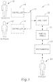
- FIG. 1 illustrates an exemplary robotic surgical system (10).
- System (10) comprises at least one controller (14) and at least one arm cart (18).
- Arm cart (18) is mechanically and/or electrically coupled to one or more robotic manipulators or arms (20).
- Each robotic arm (20) comprises one or more surgical instruments (22) for performing various surgical tasks on a patient (24).
- Operation of arm cart (18), including arms (20) and instruments (22) may be directed by a clinician (12) from controller (14).
- a second controller (14') operated by a second clinician (12'), may also direct operation of the arm cart (18) in conjunction with the first clinician (12').
- each of the clinicians (12, 12') may control different arms (20) of the cart or, in some cases, complete control of arm cart (18) may be passed between the clinicians (12, 12').
- additional arm carts may be utilized on the patient (24). These additional arm carts may be controlled by one or more of the controllers (14, 14').
- Arm cart(s) (18) and controllers (14, 14') may be in communication with one another via a communications link (16), which may be any suitable type of wired and/or wireless communications link carrying any suitable type of signal (e.g., electrical, optical, infrared, etc.) according to any suitable communications protocol.
- Communications link (16) may be an actual physical link or it may be a logical link that uses one or more actual physical links. When the link is a logical link the type of physical link may be a data link, uplink, downlink, fiber optic link, point-to-point link, for example, as is well known in the computer networking art to refer to the communications facilities that connect nodes of a network.
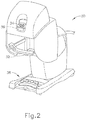
- FIG. 2 shows an exemplary controller (30) that may serve as a controller (14) of system (10).
- controller (30) generally includes user input assembly (32) having precision user input features (not shown) that are grasped by the surgeon and manipulated in space while the surgeon views the surgical procedure via a stereo display (34).
- the user input features of user input assembly (32) may include manual input devices that move with multiple degrees of freedom; and that include an actuatable handle for intuitively actuating tools (e.g., for closing grasping saws, applying an electrical potential to an electrode, etc).
- Controller (30) of the present example also includes an array of footswitches (38) providing additional control of arms (20) and instruments (22) to the surgeon.
- Display (34) may show views from one or more endoscopes viewing the surgical site within the patient and/or any other suitable view(s).
- a feedback meter (36) may be viewed through the display (34) and provide the surgeon with a visual indication of the amount of force being applied to a component of instrument (22) (e.g., a cutting member or clamping member, etc.).
- Other sensor arrangements may be employed to provide controller (30) with an indication as to whether a staple cartridge has been loaded into an end effector of instrument (22), whether an anvil of instrument (22) has been moved to a closed position prior to firing, and/or some other operational condition of instrument (22).
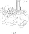
- FIG. 3 shows an exemplary robotic arm cart (40) that may serve as of arm cart (18) of system (10).
- arm cart (40) is operable to actuate a plurality of surgical instruments (50). While three instruments (50) are shown in this example, it should be understood that arm cart (40) may be operable to support and actuate any suitable number of surgical instruments (50).
- Surgical instruments (50) are each supported by a series of manually articulatable linkages, generally referred to as set-up joints (44), and a robotic manipulator (46). These structures are herein illustrated with protective covers extending over much of the robotic linkage.
- These protective covers may be optional, and may be limited in size or entirely eliminated in some versions to minimize the inertia that is encountered by the servo mechanisms used to manipulate such devices, to limit the volume of moving components so as to avoid collisions, and to limit the overall weight of cart (40).
- Each robotic manipulator (46) terminates at an instrument platform (70), which is pivotable, rotatable, and otherwise movable by manipulator (46).
- Each platform includes an instrument dock (72) that is slidable along a pair of tracks (74) to further position instrument (50). Such sliding is motorized in the present example.
- Each instrument dock (72) includes mechanical and electrical interfaces that couple with an interface assembly (52) of instrument (50).
- dock (72) may include four rotary outputs that couple with complementary rotary inputs of interface assembly (52).
- Such rotary drive features may drive various functionalities in instrument (50), such as is described in various references cited herein and/or as is described in greater detail below.
- Electrical interfaces may establish communication via physical contact, inductive coupling, and/or otherwise; and may be operable to provide electrical power to one or more features in instrument (50), provide commands and/or data communication to instrument (50), and/or provide commands and/or data communication from instrument (50).
- instrument dock (72) may mechanically and electrically communicate with an interface assembly (52) of an instrument (50) will be apparent to those of ordinary skill in the art in view of the teachings herein.
- instrument (50) may include one or more cables that couple with a separate power source and/or control unit, to provide communication of power and/or commands/data to/from instrument (50).
- Arm cart (40) of the present example also includes a base (48) that is movable (e.g., by a single attendant) to selectively position arm cart (40) in relation to a patient.
- Cart (40) may generally have dimensions suitable for transporting the cart (40) between operating rooms.
- Cart (40) may be configured to fit through standard operating room doors and onto standard hospital elevators.
- an automated instrument reloading system (not shown) may also be positioned in or near the work envelope (60) of arm cart (40), to selectively reload components (e.g., staple cartridges, etc.) of instruments (50).
- system (10) may be constructed in accordance with at least some of the teachings of U.S. Pat. No. 5,792,135 ; U.S. Pat. No. 5,817,084 ; U.S. Pat. No. 5,878,193 ; U.S. Pat. No. 6,231,565 ; U.S. Pat. No. 6,783,524 ; U.S. Pat. No. 6,364,888 ; U.S. Pat. No. 7,524,320 ; U.S. Pat. No. 7,691,098 ; U.S. Pat. No. 7,806,891 ; U.S. Pat. No. 7,824,401 ; and/or U.S. Pub. No. 2013/0012957 . Still other suitable features and operabilities that may be incorporated into system (10) will be apparent to those of ordinary skill in the art in view of the teachings herein.
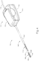
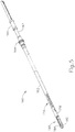
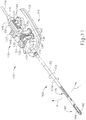
- FIGS. 4-13 show an exemplary electrosurgical instrument (100) that may be used as at least one instrument (50) within system (10). At least part of instrument (100) may be constructed and operable in accordance with at least some of the teachings of U.S. Pat. No. 6,500,176 ; U.S. Pat. No. 7,112,201 ; U.S. Pat. No. 7,125,409 ; U.S. Pat. No. 7,169,146 ; U.S. Pat. No. 7,186,253 ; U.S. Pat. No. 7,189,233 ; U.S. Pat. No. 7,220,951 ; U.S. Pat. No. 7,309,849 ; U.S. Pat. No.
- instrument (100) is operable to cut tissue and seal or weld tissue (e.g., a blood vessel, etc.) substantially simultaneously.
- instrument (100) operates similar to an endocutter type of stapler, except that instrument (100) provides tissue welding through application of bipolar RF energy instead of providing lines of staples to join tissue. It should also be understood that instrument (100) may have various structural and functional similarities with the ENSEAL® Tissue Sealing Device by Ethicon Endo-Surgery, Inc., of Cincinnati, Ohio. Furthermore, instrument (100) may have various structural and functional similarities with the devices taught in any of the other references that are cited and incorporated by reference herein.
- Instrument (100) of the present example includes an interface assembly (110), a shaft assembly (160), an articulation section (170), and an end effector (180).
- Interface assembly (110) is configured to couple with a dock (72) of robotic arm cart (40) and is thereby further operable to drive articulation section (170) and end effector (180) as will be described in greater detail below.
- instrument (100) is operable to articulate end effector (180) to provide a desired positioning relative to tissue (e.g., a large blood vessel, etc.), then sever the tissue and apply bipolar RF energy to the tissue with end effector (180) to thereby seal the tissue.
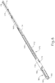
- Shaft assembly (160) of the present example extends distally from interface assembly (110). Articulation section (170) is located at the distal end of shaft assembly (160), with end effector (180) being located distal to articulation section (170). Shaft assembly (160) includes an outer sheath (162) that encloses drive features and electrical features that couple interface assembly (110) with articulation section (170) and end effector (180). As best seen in FIG. 5 , shaft assembly (160) further includes a unitary rotary coupling (164) and a firing beam coupling (166). Shaft assembly (160) is rotatable about the longitudinal axis defined by sheath (162), relative to interface assembly (110), via rotary coupling (164).
- Such rotation may provide rotation of end effector (180), articulation section (170), and shaft assembly (160) unitarily.
- rotary coupling (164) is operable to rotate end effector (180) without rotating any portion of shaft assembly (160) that is proximal of articulation section (170).
- instrument (100) may include one rotation control that provides rotatability of shaft assembly (160) and end effector (180) as a single unit; and another rotation control that provides rotatability of end effector (180) without rotating any portion of shaft assembly (160) that is proximal of articulation section (170).
- Other suitable rotation schemes will be apparent to those of ordinary skill in the art in view of the teachings herein.
- rotatable features may simply be omitted if desired.
- Articulation section (170) is operable to selectively position end effector (180) at various angles relative to the longitudinal axis defined by sheath (162).
- Articulation section (170) may take a variety of forms.
- articulation section (170) may be configured in accordance with one or more teachings of U.S. Pub. No. 2012/0078247 .
- articulation section (170) may be configured in accordance with one or more teachings of U.S. Pub. No. 2012/0078248 , entitled "Articulation Joint Features for Articulating Surgical Device," published March 29, 2012.
- Various other suitable forms that articulation section (170) may take will be apparent to those of ordinary skill in the art in view of the teachings herein. It should also be understood that some versions of instrument (10) may simply lack articulation section (170).
- articulation section (170) of the present example comprises a ribbed body (172) with a pair of articulation beams (174, 176) extending through ribbed body (172). An upper half of ribbed body (172) is omitted in FIG. 6 .
- Articulation beams (174, 176) are distally anchored within a tube (178) that is positioned between end effector (180) and articulation section (170). Articulation beams (174, 176) are operable to articulate end effector (180) by laterally deflecting end effector (180) away from the longitudinal axis defined by sheath (162).
- end effector (180) will deflect toward articulation beam (174) when articulation beam (174) is retracted proximally while articulation beam (176) is advanced distally.
- End effector (180) will deflect toward articulation beam (176) when articulation beam (176) is retracted proximally while articulation beam (174) is advanced distally.
- articulation beams (174, 176) may be opposingly translated will be described in greater detail below, while still other examples will be apparent to those of ordinary skill in the art in view of the teachings herein.
- a spacer body (177) is positioned between articulation beams (174, 176) and is operable to maintain beams (174, 176) in a substantially straight, separated relationship.
- End effector (180) of the present example comprises a first jaw (182) and a second jaw (184).
- first jaw (182) is substantially fixed relative to shaft assembly (160); while second jaw (184) pivots relative to shaft assembly (160), toward and away from first jaw (182).
- actuators such as rods or cables, etc.
- jaws (182, 184) may instead have any other suitable kind of movement and may be actuated in any other suitable fashion.
- jaws (182, 184) may be actuated and thus closed by longitudinal translation of a firing beam (190), such that actuator rods/cables/etc. may simply be eliminated in some versions.
- first jaw (182) defines a longitudinally extending elongate slot (183); while second jaw (184) also defines a longitudinally extending elongate slot (185).
- first electrode surface (186) presents a first electrode surface (186); while the underside of second jaw (184) presents a second electrode surface (187).
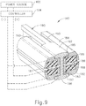
- Electrode surface (186, 187) are in communication with an electrical source (102) via one or more conductors (not shown) that extend along the length of shaft assembly (160).
- Electrical source (102) is operable to deliver RF energy to first electrode surface (186) at a first polarity and to second electrode surface (187) at a second (opposite) polarity, such that RF current flows between electrode surface (186, 187) and thereby through tissue captured between jaws (182, 184).
- firing beam (190) serves as an electrical conductor that cooperates with electrode surface (186, 187) (e.g., as a ground return) for delivery of bipolar RF energy captured between jaws (182, 184).
- Electrical source (102) may be external to instrument (100) or may be integral with instrument (100), as described in one or more references cited herein or otherwise.
- a controller (104) regulates delivery of power from electrical source (102) to electrode surfaces (186, 187). Controller (104) may also be external to instrument (100) or may be integral with electrosurgical instrument (100), as described in one or more references cited herein or otherwise. It should also be understood that electrode surfaces (186, 187) may be provided in a variety of alternative locations, configurations, and relationships. It should also be understood that power source (102) and/or controller (104) may be configured in accordance with at least some of the teachings of U.S. Provisional Pat. App. No. 61/550,768 , entitled “Medical Instrument,” filed October 24, 2011; U.S.
- first jaw (182) includes a longitudinally extending recess (197) adjacent to slot (183); while the upper side of second jaw (184) includes a longitudinally extending recess (193) adjacent to slot (185).
- FIG. 2 shows the upper side of first jaw (182) including a plurality of teeth serrations (188).
- the lower side of second jaw (184) may include complementary serrations that nest with serrations (188), to enhance gripping of tissue captured between jaws (182, 184) without necessarily tearing the tissue.
- serrations (188) may take any other suitable form or may be simply omitted altogether.
- serrations (188) may be formed of an electrically non-conductive, or insulative, material, such as plastic, glass, and/or ceramic, for example, and may include a treatment such as polytetrafluoroethylene, a lubricant, or some other treatment to substantially prevent tissue from getting stuck to jaws (182, 184).
- shaft assembly (160) and end effector (180) are sized and configured to fit through trocars having various inner diameters, such that instrument (100) is usable in minimally invasive surgery, though of course instrument (100) could also be used in open procedures if desired.
- shaft assembly (160) and end effector (180) may present an outer diameter of approximately 5 mm.
- shaft assembly (160) and end effector (180) may present any other suitable outer diameter (e.g., between approximately 2 mm and approximately 20 mm, etc.).
- end effector (180) includes one or more sensors (not shown) that are configured to sense a variety of parameters at end effector (180), including but not limited to temperature of adjacent tissue, electrical resistance or impedance of adjacent tissue, voltage across adjacent tissue, forces exerted on jaws (182, 184) by adjacent tissue, etc.
- end effector (180) may include one or more positive temperature coefficient (PTC) thermistor bodies (189) (e.g., PTC polymer, etc.), located adjacent to electrodes (186, 187) and/or elsewhere.
- PTC positive temperature coefficient
- Controller (104) may process such data in a variety of ways.
- controller (104) may modulate or otherwise change the RF energy being delivered to electrode surface (186, 187), based at least in part on data acquired from one or more sensors at end effector (180).
- controller (104) may alert the user to one or more conditions via an audio and/or visual feedback device (e.g., speaker, lights, display screen, etc.), based at least in part on data acquired from one or more sensors at end effector (180).
- an audio and/or visual feedback device e.g., speaker, lights, display screen, etc.
- some kinds of sensors need not necessarily be in communication with controller (104), and may simply provide a purely localized effect at end effector (180).
- PTC thermistor bodies (189) at end effector (180) may automatically reduce the energy delivery at electrode surface (186, 187) as the temperature of the tissue and/or end effector (180) increases, thereby reducing the likelihood of overheating.
- a PTC thermistor element is in series with power source (102) and electrode surface (186, 187); and the PTC thermistor provides an increased impedance (reducing flow of current) in response to temperatures exceeding a threshold.
- electrode surface (186, 187) may be used as sensors (e.g., to sense tissue impedance, etc.).
- sensors e.g., to sense tissue impedance, etc.
- Firing beam (190) is longitudinally movable along part of the length of end effector (180). Firing beam (190) is coaxially positioned within shaft assembly (160), extends along part of the length of shaft assembly (160), and translates longitudinally within shaft assembly (160) (including articulation section (170) in the present example), though it should be understood that firing beam (190) and shaft assembly (160) may have any other suitable relationship. As shown in FIG. 6 , firing beam (190) is secured to a firing block (168), such that firing beam (190) and firing block (168) translate unitarily together within sheath (162). Firing block (168) is secured to firing tube (167), which is best seen in FIG. 5 . Firing block (168) and firing tube (167) translate unitarily together within sheath (162). Firing beam coupling (166) is secured to firing tube (167), such that translating firing beam coupling (166) will translate firing beam (190) through the above-described couplings.
- Firing beam (190) includes a sharp distal blade (194), an upper flange (192), and a lower flange (196). As best seen in FIGS. 8-9 , distal blade (194) extends through slots (183, 185) of jaws (182, 184), with upper flange (192) being located above jaw (184) in recess (59) and lower flange (196) being located below jaw (182) in recess (58).
- the configuration of distal blade (194) and flanges (62, 66) provides an "I-beam" type of cross section at the distal end of firing beam (190).
- flanges (192, 196) extend longitudinally only along a small portion of the length of firing beam (190) in the present example, it should be understood that flanges (192, 196) may extend longitudinally along any suitable length of firing beam (190).
- flanges (192, 196) are positioned along the exterior of jaws (182, 184), flanges (192, 196) may alternatively be disposed in corresponding slots formed within jaws (182, 184).
- each jaw (182, 184) may define a "T"-shaped slot, with parts of distal blade (194) being disposed in one vertical portion of each "T"-shaped slot and with flanges (192, 196) being disposed in the horizontal portions of the "T"-shaped slots.
- Various other suitable configurations and relationships will be apparent to those of ordinary skill in the art in view of the teachings herein.
- Distal blade (194) is substantially sharp, such that distal blade (194) will readily sever tissue that is captured between jaws (182, 184). Distal blade (194) is also electrically grounded in the present example, providing a return path for RF energy as described elsewhere herein. In some other versions, distal blade (194) serves as an active electrode. In addition or in the alternative, distal blade (194) may be selectively energized with ultrasonic energy (e.g., harmonic vibrations at approximately 55.5 kHz, etc.).
- ultrasonic energy e.g., harmonic vibrations at approximately 55.5 kHz, etc.
- firing beam (190) provides closure of jaws (182, 184) as firing beam (190) is advanced distally.
- flange (192) urges jaw (184) pivotally toward jaw (182) as firing beam (190) is advanced from a proximal position to a distal position, by bearing against recess (193) formed in jaw (184).
- This closing effect on jaws (182, 184) by firing beam (190) may occur before distal blade (194) reaches tissue captured between jaws (182, 184).
- Such staging of encounters by firing beam (190) may reduce the force required to actuate firing beam (190) distally through a full firing stroke.
- firing beam (190) may have already overcome an initial resistance required to substantially close jaws (182, 184) on tissue before encountering resistance from severing the tissue captured between jaws (182, 184).
- any other suitable staging may be provided.
- flange (192) is configured to cam against a ramp feature at the proximal end of jaw (184) to open jaw (184) when firing beam (190) is retracted to a proximal position and to hold jaw (184) open when firing beam (190) remains at the proximal position.
- This camming capability may facilitate use of end effector (180) to separate layers of tissue, to perform blunt dissections, etc., by forcing jaws (182, 184) apart from a closed position.
- jaws (182, 184) are resiliently biased to an open position by a spring or other type of resilient feature.
- jaws (182, 184) close or open as firing beam (190) is translated in the present example, it should be understood that other versions may provide independent movement of jaws (182, 184) and firing beam (190).
- one or more cables, rods, beams, or other features may extend through shaft assembly (160) to selectively actuate jaws (182, 184) independently of firing beam (190).
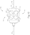
- FIGS. 4 and 10-13 show interface assembly (110) of the present example in greater detail.
- interface assembly (110) comprises a housing (112), a base (114), and a cable (118).
- Housing (112) comprises a shell that simply encloses drive components.
- housing (112) also includes an electronic circuit board, chip, and/or other feature that is configured to identify instrument (100). Such identification may be carried out through cable (118).
- Cable (118) is configured to couple with power source (102) and controller (104).
- a strain relief (119) is provided at the interface of cable (118) and housing (112). It should be noted that housing (112) is omitted from FIGS. 11-13 for the sake of clarity.
- Base (114) includes a mounting plate (116) that engages dock (72) of robotic arm cart (40). It should be noted that plate (116) is omitted from FIGS. 12-13 for the sake of clarity. While not shown, it should be understood that base (114) may also include one or more electrical contacts and/or other features operable to establish electrical communication with a complementary feature of dock (72).
- a shaft support structure (122) extends upwardly from base (114) and provides support to shaft assembly (160) (while still allowing shaft assembly (160) to rotate).
- shaft support structure (122) may include a busing, bearings, and/or other features that facilitate rotation of shaft assembly (160) relative to support structure (122). As shown in FIG.
- base (114) further includes four drive discs (120) that are rotatable relative to plate (116).
- Each disc (120) includes a pair of unitary pins (121) that couple with complementary recesses (not shown) in drive elements of dock (72). In some versions, one pin (121) of each pair is closer to the axis of rotation of the corresponding disc (120), to ensure proper angular orientation of disc (120) relative to the corresponding drive element of dock (72).
- a drive shaft (124, 125, 126, 127) extends unitarily upwardly from each disc (120).
- discs (120) are operable to provide independent rotation of shaft assembly (160), bending of articulation section (170), and translation of firing beam (190), through rotation of drive shafts (124, 125, 126, 127).
- a first helical gear (130) is fixedly secured to drive shaft (124), such that rotation of the corresponding disc (120) provides rotation of first helical gear (130).
- First helical gear (130) meshes with a second helical gear (132), which is fixedly secured to rotary coupling (164).
- rotation of first helical gear (130) provides rotation of shaft assembly (160).
- rotation of first helical gear (130) about a first axis is converted into rotation of second helical gear (132) about a second axis, which is orthogonal to the first axis.
- a clockwise (CW) rotation of second helical gear (132) results in CW rotation of shaft assembly (160).
- a counter-clockwise (CCW) rotation of second helical gear (132) results in CCW rotation of shaft assembly (160).
- CCW rotation of shaft assembly (160) Other suitable ways in which shaft assembly (160) may be rotated will be apparent to those of ordinary skill in the art in view of the teachings herein.
- a spur gear (134) is fixedly secured to drive shaft (125), such that rotation of the corresponding disc (120) provides rotation of spur gear (134).
- Spur gear (134) meshes with a first spur pinion (136), which is fixedly secured to a pinion shaft (138).
- Pinion shaft (138) is supported by base (116) and rotates freely relative to base (116), such that first spur pinion (136) is rotatable as an idler. It should therefore be understood that first spur pinion (136) rotates in response to rotation of spur gear (134).
- First spur pinion (136) also meshes with a rack (140), which is fixedly secured to a drive block (142).
- firing beam (190) is operable to first close jaws (182, 184) together about tissue during a first range of distal travel of firing beam (190); then sever the tissue clamped between jaws (182, 184) during a first range of distal travel of firing beam (190).
- tissue may be clamped and severed by rotation of drive shaft (125) via its corresponding disc (120).
- firing beam (190) retracts proximally, ultimately opening jaws (182, 184) to release tissue.
- Other suitable ways in which firing beam (190) may be translated will be apparent to those of ordinary skill in the art in view of the teachings herein.
- FIGS. 11-12 show a second spur pinion (144) fixedly secured to drive shaft (126), such that rotation of the corresponding disc (120) provides rotation of second spur pinion (144).
- Second spur pinion (144) meshes with a left rack (146), which is fixedly secured to articulation beam (174).
- articulation beam (174) will translate distally or proximally in response to rotation of drive shaft (126).
- FIGS. 11 and 13 show a third spur pinion (148) fixedly secured to drive shaft (127), such that rotation of the corresponding disc (120) provides rotation of third spur pinion (148).
- Third spur pinion (148) meshes with a right rack (150), which is fixedly secured to articulation beam (176). It should be understood that articulation beam (176) will translate distally or proximally in response to rotation of drive shaft (127).
- drive shafts (126, 127) may be rotated in the same direction simultaneously in order to provide opposing translation of beams (174, 176).
- drive shaft (126) may be rotated clockwise to retract beam (174) proximally, with drive shaft (127) being rotated clockwise to advance beam (176) distally, to thereby deflect end effector (180) to the left (L) at articulation section (170).
- drive shaft (126) may be rotated counter-clockwise to advance beam (174) distally, with drive shaft (127) being rotated counter-clockwise to retract beam (176) proximally, to deflect end effector (180) to the left (R) at articulation section (170).
- end effector (180) may be articulated at articulation section (170)
- articulation control may be provided in accordance with at least some of the teachings of U.S. Pub. No. 2012/0078243 ; and/or U.S. Pub. No. 2013/0023868 . It should also be understood that some versions of instrument (100) may simply lack an articulation section (170) and corresponding control.
- arm cart (40) is used to insert end effector (180) into a patient via a trocar.
- Articulation section (170) is substantially straight when end effector (180) and part of shaft assembly (160) are inserted through the trocar.
- Drive shaft (124) may be rotated through drive features in dock (72) that are coupled with the corresponding disc (120), to position end effector (180) at a desired angular orientation relative to the tissue.
- Drive shafts (126, 126) may then be rotated through drive features in dock (72) that are coupled with the corresponding discs (120), to pivot or flex articulation section (170) of shaft assembly (160) in order to position end effector (180) at a desired position and orientation relative to an anatomical structure within the patient.
- tissue of the anatomical structure are then captured between jaws (182, 184) by rotating drive shaft (125) to advance firing beam (190) distally through a first range of motion.
- Such layers of tissue may be part of the same natural lumen defining anatomical structure (e.g., blood vessel, portion of gastrointestinal tract, portion of reproductive system, etc.) in a patient.
- one tissue layer may comprise the top portion of a blood vessel while the other tissue layer may comprise the bottom portion of the blood vessel, along the same region of length of the blood vessel (e.g., such that the fluid path through the blood vessel before use of instrument (100) is perpendicular to the longitudinal axis defined by end effector (180), etc.).
- the lengths of jaws (182, 184) may be oriented perpendicular to (or at least generally transverse to) the length of the blood vessel.
- flanges (192, 196) cammingly act to pivot jaw (182) toward jaw (184) when firing beam (190) is actuated distally by rotating drive shaft (125).
- firing beam (190) continues to advance distally in response to continued rotation of drive shaft (125).
- distal blade (194) simultaneously severs the clamped tissue layers, resulting in separated upper layer portions being apposed with respective separated lower layer portions. In some versions, this results in a blood vessel being cut in a direction that is generally transverse to the length of the blood vessel.
- flanges (192, 196) immediately above and below jaws (182, 184), respectively, may help keep jaws (182, 184) in a closed and tightly clamping position.
- flanges (192, 196) may help maintain a significantly compressive force between jaws (182, 184).
- electrode surfaces (186, 187) are activated with bipolar RF energy by the surgeon providing a corresponding command input through controller (30) (e.g., through user input assembly (32) or footswitches (38), etc.).
- electrodes (186, 187) are selectively coupled with power source (102) such that electrode surface (186, 187) of jaws (182, 184) are activated with a common first polarity while firing beam (190) is activated at a second polarity that is opposite to the first polarity.
- a bipolar RF current flows between firing beam (190) and electrode surfaces (186, 187) of jaws (182, 184), through the compressed regions of severed tissue layer portions.
- electrode surface (186) has one polarity while electrode surface (187) and firing beam (190) both have the other polarity.
- bipolar RF energy delivered by power source (102) ultimately thermally welds the tissue layer portions on one side of firing beam (190) together and the tissue layer portions on the other side of firing beam (190) together.
- the heat generated by activated electrode surfaces (186, 187) can denature the collagen within the tissue layer portions and, in cooperation with clamping pressure provided by jaws (182, 184), the denatured collagen can form a seal within the tissue layer portions.
- the severed ends of the natural lumen defining anatomical structure are hemostatically sealed shut, such that the severed ends will not leak bodily fluids.
- electrode surface (186, 187) may be activated with bipolar RF energy before firing beam (190) even begins to translate distally and thus before the tissue is even severed.
- Other suitable ways in which instrument (100) may be operable and operated will be apparent to those of ordinary skill in the art in view of the teachings herein.
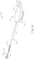
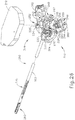
- FIG. 14 shows an exemplary alternative electrosurgical instrument (200).
- Instrument (200) of this example is substantially similar to instrument (100) described above in that instrument (200) has an articulation section (270) and an end effector (280) that are substantially identical to articulation section (170) and end effector (180) described above.
- Instrument (200) of this example is also operable to couple with a dock (72) of robotic arm cart (40) via an interface assembly (210).
- interface assembly (210) of this example is different from interface assembly (110) described above.
- Instrument (200) of this example also comprises a shaft assembly (260) which is substantially similar to shaft assembly (160) described above.
- shaft assembly (260) of this example is different from shaft assembly (160) described above - primarily in how shaft assembly (260) associates with interface assembly (210) compared to the association of shaft assembly (160) and interface assembly (110) described above.
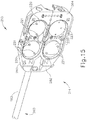
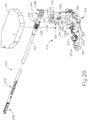
- FIGS. 15-18 show interface assembly (210) of the present example in greater detail.
- Interface assembly (210) comprises a housing (212), a pivoting base (214), and a cable (218).
- Housing (212) comprises a shell that simply encloses drive components.
- housing (212) also includes an electronic circuit board, chip, and/or other feature that is configured to identify instrument (200). Such identification may be carried out through cable (218).
- Cable (218) is configured to couple with a power source (not shown) and a controller (not shown).
- a strain relief (219) is provided at the interface of cable (218) and housing (212).
- housing (212) is omitted from FIGS. 16-18 , 23-24 , and 28-29 for the sake of clarity.
- cable (218) and strain relief (219) are merely optional.
- some versions of interface assembly (210) may include an integral power source (e.g., a battery, etc.).
- pivoting base (214) includes three separable sections (281, 282, 284). While not shown, it should be understood that pivoting base (214) may also include one or more electrical contacts and/or other features operable to establish electrical communication with a complementary feature of dock (72).
- a shaft support structure (222) extends upwardly from pivoting base (214) and provides support to shaft assembly (260) (while still allowing shaft assembly (260) to rotate).
- Shaft support structure (222) of the present example comprises a first portion (222A) and a second portion (222B).
- shaft support structure (222) may include a bushing, bearings, and/or other features that facilitate rotation of shaft assembly (260) relative to support structure (222). As shown in FIG.
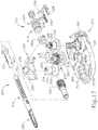
- pivoting base (214) further includes three drive discs (220) and one idle disc (223).
- the drive discs (220) are rotatable within base (214).
- Drive discs (220) each include a respective pair of unitary pins (221) that couple with complementary recesses (not shown) in corresponding drive elements of dock (72).
- one pin (221) of each pair is closer to the axis of rotation of the corresponding drive disc (220), to ensure proper angular orientation of drive disc (220) relative to the corresponding drive element of dock (72).
- a drive shaft (224, 225, 226) extends unitarily upwardly from each drive disc (220).
- drive discs (220) are operable to provide independent rotation of shaft assembly (260), bending of articulation section (270), and translation of firing beam (190), through rotation of drive shafts (224, 225, 226).
- idle disc (223) may be utilized in some versions and various methods of utilization and/or incorporation will be apparent to those of ordinary skill in the art in view of the teachings herein.
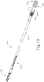
- FIG. 19 shows shaft assembly (260) of the present example in greater detail.
- Shaft assembly (260) is substantially similar to shaft assembly (160) as discussed above.
- shaft assembly (260) is different in that shaft assembly (260) comprises a first helical gear (232) in place of rotary coupling (164), a firing beam coupling (266) in place of firing beam coupling (166); and additionally a first slide bushing (247) and a second slide bushing (249).
- first helical gear (232) is operable to rotate shaft assembly (260) and end effector (280)
- firing beam coupling (266) is operable to drive firing beam (190)
- slide bushings (247, 249) are operable to articulate end effector (280) at articulation section (270).
- a second helical gear (230) is fixedly secured to drive shaft (224), such that rotation of the corresponding drive disc (220) provides rotation of second helical gear (230).
- Second helical gear (230) meshes with first helical gear (232), which is fixedly secured to an outer sheath (162) of shaft assembly (260).
- first helical gear (232) is fixedly secured to an outer sheath (162) of shaft assembly (260).
- rotation of second helical gear (230) provides rotation of shaft assembly (260). It should be understood that rotation of second helical gear (230) about a first axis is converted into rotation of first helical gear (232) about a second axis, which is orthogonal to the first axis.
- a clockwise (CW) rotation of second helical gear (230) results in CW rotation of shaft assembly (260) (viewed from the proximal end).
- a counter-clockwise (CCW) rotation of second helical gear (230) results in CCW rotation of shaft assembly (260) (viewed from the proximal end).
- an eccentric cam (234) is fixedly secured to drive shaft (225), such that rotation of the corresponding drive disc (220) provides rotation of eccentric cam (234).
- Eccentric cam (234) is disposed within an oblong recess (252) of a first rack (250). As best seen in FIG. 18 , oblong recess (252) is oriented such that rotation of eccentric cam (234) results in translation of first rack (250) along a path that is parallel to a longitudinal axis defined by outer sheath (162) but not transverse to the longitudinal axis defined by outer sheath (162).
- first rack (250) translates parallel to the longitudinal axis defined by outer sheath (162) in response to rotation of eccentric cam (234).
- first rack (250) comprises a first fork (251) oriented transverse to the longitudinal axis defined by outer sheath (162).
- First fork (251) of first rack (250) is coupled to firing beam coupling (266) such that firing beam coupling (266) translates longitudinally with first rack (250).
- Firing beam coupling (266) is configured to operate substantially similar to firing beam coupling (166) discussed above. Therefore, as discussed above in relation to firing beam coupling (166), translation of firing beam coupling (266) will translate firing beam (190).
- rotation of eccentric cam (234) is converted to longitudinal translation of firing beam (190) via first rack (250) and firing beam coupling (266).
- firing beam (190) is operable to first close jaws (182, 184) together about tissue during a first range of distal travel of firing beam (190); then sever the tissue clamped between jaws (182, 184) during a first range of distal travel of firing beam (190).
- tissue may be clamped and severed by rotation of drive shaft (225) via its corresponding drive disc (220).
- firing beam (190) retracts proximally, ultimately opening jaws (182, 184) to release tissue.
- FIGS. 16-18 show a spur pinion (244) fixedly secured to drive shaft (226), such that rotation of the corresponding drive disc (220) provides rotation of second spur pinion (244).
- Spur pinion (244) meshes with a laterally outwardly facing second rack (246).
- second rack (246) comprises a second fork (256) oriented transverse to the longitudinal axis defined by outer sheath (162). Second fork (256) of second rack (246) is coupled to a first slide bushing (247) such that first slide bushing (247) translates longitudinally with second rack (246).
- Firing tube (167) is slidably disposed within a central bore of first slide bushing (247) such that first slide bushing (247) is capable of translation along a longitudinal axis defined by firing tube (167).
- a proximal portion of firing tube (167) includes longitudinally extending slots (137).
- First slide bushing (247) is fixedly secured to articulation beam (174), which is disposed within a central bore of firing beam (167), via one of the longitudinally extending slots (137). It should therefore be understood that articulation beam (174) will translate distally or proximally in response to rotation of drive shaft (226).
- Spur pinion (244) also meshes with a laterally inwardly facing third rack (248).
- third rack (248) comprises a third fork (258) oriented transverse to the longitudinal axis defined by outer sheath (162).
- Third fork (258) of third rack (248) is coupled to a second slide bushing (249) such that second slide bushing (249) translates longitudinally with third rack (248).
- Firing tube (167) is slidably disposed within a central bore of second slide bushing (249) such that second slide bushing (249) is capable of translation along the longitudinal axis defined by firing tube (167).
- Second slide bushing (249) is fixedly secured to articulation beam (176), which is disposed within a central bore of firing beam (167), via the other one of the longitudinally extending slots (137). It should therefore be understood that articulation beam (176) will translate distally or proximally in response to rotation of drive shaft (226).
- Slots (137) are configured to enable free translation of firing tube (167) relative to slide bushings (247,249), to thus enable free actuation of firing beam (190) regardless of the articulation state of articulation section (270).
- slots (137) are configured to enable free translation of slide bushings (247,249) relative to firing tube (167), to thus enable free articulation of articulation section (270) regardless of the longitudinal position of firing beam (190).
- second rack (246) and third rack (248) mesh with spur pinion (244) on opposite sides of spur pinion (244) such that rotation of spur pinion (244) will cause second rack (246) and third rack (248) to translate in opposite directions along paths that are parallel to the longitudinal axis defined by outer sheath (162).
- a CW rotation of spur pinion (244) results in translation of second rack (246) proximally away from end effector (280) and in translation of third rack (248) distally toward end effector (280).
- a CCW rotation of spur pinion (244) results in translation of second rack (246) distally toward end effector (280) and in translation of third rack (248) proximally away from end effector (280).
- shaft assembly (260) of the present example is provided as a disposable component while interface assembly (210) is provided as a reusable component. Therefore, among other things, interface assembly (210) is configured to facilitate installation and removal of shaft assembly (260) from surgical instrument (200).
- pivoting base (214) of the present example comprises three separable sections (281, 282, 284). A first section (281) and a second section (282) are pivotably coupled to a proximal section (284). Certain drive components discussed above pivot with particular sections (281, 282) of pivoting base (214).
- first section (281) comprises first portion (222A) of support structure (222), second helical gear (230), spur pinion (244), second rack (246), third rack (248), drive shaft (224), drive shaft (226), and two of the three drive discs (220) among other components.
- Second section (282) comprises second portion (222B) of support structure (222), eccentric cam (234), first rack (250), drive shaft (225), idle disc (223) and one of the three drive discs (220) among other components.
- first section (281) and second section (282) are substantially symmetric portions of pivoting base (214).
- proximal section (284) is defined by a portion of pivoting base (214) having been severed along a line (292) transverse to the longitudinal axis defined by outer sheath (162) and relative to the proximal end of interface assembly (210).
- First section (281) and second section (282) are defined by the remaining portion of pivoting base (214) having been divided along a line (290) parallel to the longitudinal axis defined by outer sheath (162).
- First section (281) and second section (282) are pivotable toward each other.
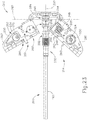
- First section (281) and second section (282) pivot about points that are located near the proximal end of base (214) and that are located along a common plane. As seen in FIG. 23 , the pivot points for first section (281) and second section (282) are at the same longitudinal position, albeit spaced apart along a common transverse path that is parallel to line (292). Although sections (281, 282, 284) are separated as described above, other suitable ways in which sections (281, 282, 284) may be configured would be apparent to those of ordinary skill in the art in view of the teachings herein.
- FIGS. 20 and 23-24 show sections (281, 282, 284) of interface assembly (210) in an open position.
- the shaft assembly (260) may be inserted into position as shown in the transition from FIG. 20 to FIG. 21 .
- sections (281, 282, 284) of interface assembly (210) are pivoted into a closed position as shown in FIG. 22 .
- first helical gear (232) with second helical gear (230), first rack (250) with firing beam coupling (266), second rack (246) with first slide bushing (247), and third rack (248) with second slide bushing (249) such that the specific couplings discussed above are made as shown in FIG. 22 .
- first fork (251) of first rack (250) enables first fork (251) to engage firing beam coupling (266) when sections (281, 282, 284) are closed toward each other.
- second fork (256) of second rack (246) enables second fork (256) to engage first slide bushing (247) when sections (281, 282, 284) are closed toward each other.
- third fork (258) of third rack (248) enables third fork (258) to engage second slide bushing (249) when sections (281, 282, 284) are closed toward each other.
- a pair of locking features (283) engages a complementary pair of recesses (285) to keep interface assembly in the closed position through a snap fitting.
- shaft assembly (260) may be removed from surgical instrument (200) by moving interface assembly (210) from the closed position shown in FIG. 22 to the open position of FIG. 20 , by pivoting sections (281, 282) outwardly.
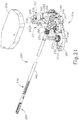
- FIGS. 25-29 show an exemplary alternative interface assembly (310).
- Interface assembly (310) of this example is substantially similar to interface assembly (210) described above, and can be readily coupled with shaft assembly (260) described above.
- interface assembly (310) of this example is different from interface assembly (210) described above - primarily in that the pivoting sections (380, 382, 384) of base (314) are configured differently from sections (281, 282, 284) of base (214).
- Pivoting base (314) of this example comprises three separable sections (380, 382, 384).
- a first section (380) and a second section (382) are pivotably coupled to a distal section (384).
- first section (380) comprises spur pinion (244), second rack (246), third rack (248), drive shaft (226), and one of the three drive discs (220) among other components.
- Second section (382) comprises eccentric cam (234), first rack (250), drive shaft (225), idle disc (223) and one of the three drive discs (220) among other components.
- Distal section (384) comprises support structure (222), second helical gear (230), and drive shaft (224) among other components.
- first section (380) is represents approximately one-quarter of pivoting base (314) and is defined by a portion of pivoting base (314) having been severed along a line (390) parallel to the longitudinal axis defined by outer sheath (162) and a line (392) transverse to the longitudinal axis defined by outer sheath (162).
- second section (382) is defined by a portion of pivoting base (314) having been severed along line (392) transverse to the longitudinal axis defined by outer sheath (162) and a line (394).
- distal section (384) is defined by a portion of pivoting base (314) having been severed along line (392) transverse to the longitudinal axis defined by outer sheath (162) and line (394).
- First section (380) and second section (382) are pivotable toward each other.
- First section (380) and second section (382) pivot about points that are located near the distal end of base (314) and that are located along a common plane.
- the pivot points for first section (380) and second section (382) are located at staggered longitudinal positions and are laterally spaced apart from each other.
- FIG. 25 shows sections (380, 382, 384) of base (314) in an open position.
- the shaft assembly (260) may be inserted into position as shown in the transition from FIG. 25 to FIG. 26 .
- sections (380, 382, 384) of base (314) are pivoted into a closed position as shown in FIG. 27 .
- first helical gear (232) with second helical gear (230), fork (251) of first rack (250) with firing beam coupling (266), second rack (246) with first slide bushing (247), and third rack (248) with second slide bushing (249) such that the specific couplings discussed above are made as shown in FIG. 27 .
- first fork (251) of first rack (250) enables first fork (251) to engage firing beam coupling (266) when sections (380, 382, 384) are closed toward each other.
- second fork (256) of second rack (246) enables second fork (256) to engage first slide bushing (247) when sections (380, 382, 384) are closed toward each other.
- third fork (258) of third rack (248) enables third fork (258) to engage second slide bushing (249) when sections (380, 382, 384) are closed toward each other. While not shown, this example could utilize locking features similar to those described above and/or any other suitable type of coupling feature to keep interface assembly in the closed position.
- shaft assembly (260) may be removed from base (314) by moving sections (380, 382) from the closed position shown in FIG. 27 to the open position of FIG. 25 , by pivoting sections (380, 382) outwardly.
- an interface assembly may include an integral power source such as a battery, and that such a battery may provide at least some of any electrical power required to operate the surgical instrument of the interface assembly.
- an interface assembly may provide electrical power to one or more components of the associated surgical instrument from a source that is internal to the interface assembly and/or from a source that is external to the interface assembly (e.g., through system (10)).
- the interface assembly may include one or more conductive clips, contacts, and/or other features that provide automatic electrical coupling with the shaft assembly when the shaft assembly is mechanically coupled with the interface assembly.
- an interface assembly may be configured to couple with a variety of types of modular shaft assemblies.
- Such modular shaft assemblies may provide inter-modality and/or intra-modality variation.
- inter-modality variation may include a single interface assembly being able to selectively couple with different shaft assemblies having a variety of end effectors that include staplers, RF electrosurgical features, ultrasonic cutting features, etc.
- intra-modality variation may include a single interface assembly being able to selectively couple with different RF electrosurgical shaft assemblies having a variety of end effectors that include straight jaws, curved jaws, etc.
- Other inter-modality variations and intra-modality variations will be apparent to those of ordinary skill in the art in view of the teachings herein.
- instrument (22) comprises an electrosurgical instrument
- system (10) may have a control algorithm whereby articulation drive controls are effectively locked in place when RF electrodes in the end effector of instrument (22) are activated with RF energy.
- a control logic may prevent end effector from being moved from that articulated/straight position when the RF electrodes are activated. Referring back to the example of instrument (100), this may include effectively locking drive shafts (126, 127) when electrodes (186, 187) are activated with RF energy.
- this may include effectively locking drive shaft (226) when electrodes in end effector (280) are activated with RF energy.
- articulation may be selectively locked based on the activation state of RF electrodes.
- an articulation lockout may be similarly provided when some other kind of activated feature (e.g., an ultrasonic blade, etc.) in an end effector is activated.
- Some versions of system (10) may also include one or more features configured to provide sounds generated in vivo during a medical procedure.
- a microphone may be incorporated into a camera, trocar, and/or instrument (22); and/or a microphone may be provided as a stand-alone instrument. Regardless of how it is incorporated into a particular support structure, the microphone may be positioned inside the patient, at the surgical site near where instrument (22) is operating. In addition or in the alternative, a microphone may be positioned externally, on the patient's skin over the surgical site. Sound captured through either or both kinds of microphones may be amplified and played through speakers, through headphones, and/or through some other kind of device. Such speakers and/or headphones may be located in the same room as the patient.
- such speakers and/or headphones may be located at controller (14), such that a remotely operating clinician may hear the in vivo sounds associated with the medical procedure being performed.
- controller 14
- these concepts are not limited to a robotic surgical context. These concepts may be readily applied to other laparoscopic surgical contexts as well.
- any of the versions of instruments described herein may include various other features in addition to or in lieu of those described above.
- any of the instruments described herein may also include one or more of the various features disclosed in any of the various references that are incorporated by reference herein.
- Versions described above may be designed to be disposed of after a single use, or they can be designed to be used multiple times. Versions may, in either or both cases, be reconditioned for reuse after at least one use. Reconditioning may include any combination of the steps of disassembly of the device, followed by cleaning or replacement of particular pieces, and subsequent reassembly. In particular, some versions of the device may be disassembled, and any number of the particular pieces or parts of the device may be selectively replaced or removed in any combination. Upon cleaning and/or replacement of particular parts, some versions of the device may be reassembled for subsequent use either at a reconditioning facility, or by a user immediately prior to a procedure.
- reconditioning of a device may utilize a variety of techniques for disassembly, cleaning/replacement, and reassembly. Use of such techniques, and the resulting reconditioned device, are all within the scope of the present application.
- versions described herein may be sterilized before and/or after a procedure.
- the device is placed in a closed and sealed container, such as a plastic or TYVEK bag.
- the container and device may then be placed in a field of radiation that can penetrate the container, such as gamma radiation, x-rays, or high-energy electrons.
- the radiation may kill bacteria on the device and in the container.
- the sterilized device may then be stored in the sterile container for later use.
- a device may also be sterilized using any other technique known in the art, including but not limited to beta or gamma radiation, ethylene oxide, or steam.
Landscapes
- Health & Medical Sciences (AREA)
- Life Sciences & Earth Sciences (AREA)
- Surgery (AREA)
- Engineering & Computer Science (AREA)
- Medical Informatics (AREA)
- Veterinary Medicine (AREA)
- Biomedical Technology (AREA)
- Heart & Thoracic Surgery (AREA)
- Nuclear Medicine, Radiotherapy & Molecular Imaging (AREA)
- Molecular Biology (AREA)
- Animal Behavior & Ethology (AREA)
- General Health & Medical Sciences (AREA)
- Public Health (AREA)
- Ophthalmology & Optometry (AREA)
- Robotics (AREA)
- Physics & Mathematics (AREA)
- Plasma & Fusion (AREA)
- Otolaryngology (AREA)
- Surgical Instruments (AREA)
Claims (15)
- Vorrichtung zum Bearbeiten von Gewebe, wobei die Vorrichtung umfasst:(a) einen Endeffektor (280);(b) eine Schaftanordnung (260),
wobei die Schaftanordnung eine Längsachse definiert, wobei die Schaftanordnung umfasst:(i) ein distales Ende, wobei der Endeffektor an dem distalen Ende der Schaftanordnung positioniert ist,(ii) ein proximales Ende, und(iii) ein erstes drehbares Element (232), wobei das erste drehbare Element fest an der Schaftanordnung angebracht ist; und(c) eine Schnittstellenanordnung (210), die mit dem proximalen Ende der Schaftanordnung verknüpft ist,und wobei der erste Abschnitt und der zweite Abschnitt betrieben werden können, um um eine oder mehrere Schwenkachsen aufeinander zu und voneinander weg zu schwenken, wobei die eine oder die mehreren Schwenkachsen senkrecht zu der Längsachse der Schaftanordnung verlaufen,
wobei die Schnittstellenanordnung umfasst:(i) eine Basis (214), dadurch gekennzeichnet, dass die Basis einen ersten Abschnitt (281) und einen zweiten Abschnitt (282) umfasst,
und wobei der erste Abschnitt der Basis ein zweites drehbares Element (230) umfasst,
wobei das erste drehbare Element und das zweite drehbare Element betrieben werden können, um eins oder beide der Schaftanordnung oder des Endeffektors um die Längsachse der Schaftanordnung zu drehen. - Vorrichtung nach Anspruch 1, wobei die Schaftanordnung ferner einen Gelenkabschnitt umfasst, wobei der Gelenkabschnitt betrieben werden kann, um mindestens einen Teil des Endeffektors von der Längsachse wegzubewegen.
- Vorrichtung nach Anspruch 1, wobei die Schnittstellenanordnung ferner eine Vielzahl von Antriebsscheiben umfasst, wobei jede der Antriebsscheiben der Vielzahl von Antriebsscheiben mit einer jeweiligen Antriebswelle verknüpft ist, wobei die Antriebswellen drehbar in dem ersten und zweiten Abschnitt der Basis angeordnet sind, und wobei das zweite drehbare Element fest an einer ersten Antriebswelle der Vielzahl von Antriebswellen angebracht ist.
- Vorrichtung nach Anspruch 3, wobei die Schaftanordnung ferner einen Gelenkabschnitt umfasst, wobei der Gelenkabschnitt betrieben werden kann, um mindestens einen Teil des Endeffektors von der Längsachse wegzubewegen, wobei die Schnittstellenanordnung ferner ein Stirnrad umfasst, wobei das Stirnrad fest an einer zweiten Antriebswelle der Vielzahl von Antriebswellen angebracht ist, und wobei das Stirnrad betrieben werden kann, um das Auslenken des Gelenkabschnitts anzutreiben.
- Vorrichtung nach Anspruch 4, wobei die Schnittstellenanordnung ferner ein erstes Gestell und ein zweites Gestell umfasst, wobei das erste Gestell und das zweite Gestell auf gegenüberliegenden Seiten des Stirnrads in das Stirnrad eingreifen und wobei das erste Gestell, das zweite Gestell und das Stirnrad betrieben werden können, um das Auslenken des Gelenkabschnitts anzutreiben, wobei optional die Schaftanordnung ferner umfasst:(i) ein erstes Gelenkband, wobei das erste Gelenkband mit einer ersten Buchse gekoppelt ist, und wobei die erste Buchse dazu ausgelegt ist, sich entlang der Längsachse der Schaftanordnung in Reaktion auf die Bewegung des ersten Gestells zu bewegen, und(ii) ein zweites Gelenkband, wobei das zweite Gelenkband mit einer zweiten Buchse gekoppelt ist, und wobei die zweite Buchse dazu ausgelegt ist, sich entlang der Längsachse der Schaftanordnung in Reaktion auf die Bewegung des zweiten Gestells zu bewegen.
- Vorrichtung nach Anspruch 4, wobei die erste Antriebswelle und die zweite Antriebswelle drehbar in demselben Abschnitt der Basis der Schnittstellenanordnung angeordnet sind.
- Vorrichtung nach Anspruch 4, wobei die erste Antriebswelle drehbar in dem ersten Abschnitt der Basis der Schnittstellenanordnung angeordnet ist und wobei die zweite Antriebswelle drehbar in dem zweiten Abschnitt der Basis der Schnittstellenanordnung angeordnet ist.
- Vorrichtung nach Anspruch 2, wobei der Endeffektor umfasst:(i) eine erste Backe, und(ii) eine zweite Backe, wobei die erste Backe in Richtung der zweiten Backe beweglich ist, um Gewebe zwischen der ersten und der zweiten Backe einzuklemmen.
- Vorrichtung nach Anspruch 8, wobei die Schnittstellenanordnung ferner einen Exzenter umfasst, wobei der Exzenter fest an einer zweiten Antriebswelle der Vielzahl von Antriebswellen angebracht ist, und wobei der Exzenter betrieben werden kann, um die erste Backe in Richtung der zweiten Backe zu treiben.
- Vorrichtung nach Anspruch 9, wobei die Schnittstellenanordnung ferner ein Gestell umfasst, wobei das Gestell eine längliche Ausnehmung definiert, wobei der Exzenter in der länglichen Ausnehmung des Gestells angeordnet ist, wobei optional die längliche Ausnehmung dazu ausgelegt ist, die Bewegung des Gestells entlang einer Längsachse parallel zu der Längsachse der Schaftanordnung in Reaktion auf die Drehung des Exzenters bereitzustellen.
- Vorrichtung nach Anspruch 9, wobei die erste Antriebswelle drehbar in dem ersten Abschnitt der Basis der Schnittstellenanordnung angeordnet ist und wobei die zweite Antriebswelle drehbar in dem zweiten Abschnitt der Basis der Schnittstellenanordnung angeordnet ist.
- Vorrichtung nach Anspruch 8, wobei mindestens eine der zwei Backen mindestens eine Elektrode umfasst, wobei die mindestens eine Elektrode betrieben werden kann, um HF-Energie an das zwischen der ersten und der zweiten Backe eingeklemmte Gewebe zu liefern.
- Vorrichtung nach Anspruch 1, wobei der erste und der zweite Abschnitt in eine offene Position schwenkbar sind, woraufhin die Schaftanordnung von der Schnittstellenanordnung entfernt werden kann.
- Vorrichtung nach Anspruch 1, wobei das erste drehbare Element und das zweite drehbare Element jeweils ein Schrägzahnrad umfassen.
- Vorrichtung nach Anspruch 1, wobei die Schnittstellenanordnung ferner ein Verriegelungselement umfasst, das dazu ausgelegt ist, den ersten Abschnitt an dem zweiten Abschnitt zu sichern.
Applications Claiming Priority (2)
| Application Number | Priority Date | Filing Date | Title |
|---|---|---|---|
| US13/798,677 US9107685B2 (en) | 2013-03-13 | 2013-03-13 | Electrosurgical device with disposable shaft having clamshell coupling |
| PCT/US2014/016416 WO2014158421A1 (en) | 2013-03-13 | 2014-02-14 | Electrosurgical device with disposable shaft having clamshell coupling |
Publications (2)
| Publication Number | Publication Date |
|---|---|
| EP2967722A1 EP2967722A1 (de) | 2016-01-20 |
| EP2967722B1 true EP2967722B1 (de) | 2020-04-15 |
Family
ID=50231535
Family Applications (1)
| Application Number | Title | Priority Date | Filing Date |
|---|---|---|---|
| EP14708178.0A Not-in-force EP2967722B1 (de) | 2013-03-13 | 2014-02-14 | Elektrochirurgische vorrichtung mit einwegschaft mit zweiteiliger kupplung |
Country Status (4)
| Country | Link |
|---|---|
| US (3) | US9107685B2 (de) |
| EP (1) | EP2967722B1 (de) |
| JP (1) | JP6316926B2 (de) |
| WO (1) | WO2014158421A1 (de) |
Families Citing this family (171)
| Publication number | Priority date | Publication date | Assignee | Title |
|---|---|---|---|---|
| US20070084897A1 (en) | 2003-05-20 | 2007-04-19 | Shelton Frederick E Iv | Articulating surgical stapling instrument incorporating a two-piece e-beam firing mechanism |
| US9060770B2 (en) | 2003-05-20 | 2015-06-23 | Ethicon Endo-Surgery, Inc. | Robotically-driven surgical instrument with E-beam driver |
| US9072535B2 (en) | 2011-05-27 | 2015-07-07 | Ethicon Endo-Surgery, Inc. | Surgical stapling instruments with rotatable staple deployment arrangements |
| US11998198B2 (en) | 2004-07-28 | 2024-06-04 | Cilag Gmbh International | Surgical stapling instrument incorporating a two-piece E-beam firing mechanism |
| US11896225B2 (en) | 2004-07-28 | 2024-02-13 | Cilag Gmbh International | Staple cartridge comprising a pan |
| US7669746B2 (en) | 2005-08-31 | 2010-03-02 | Ethicon Endo-Surgery, Inc. | Staple cartridges for forming staples having differing formed staple heights |
| US10159482B2 (en) | 2005-08-31 | 2018-12-25 | Ethicon Llc | Fastener cartridge assembly comprising a fixed anvil and different staple heights |
| US11246590B2 (en) | 2005-08-31 | 2022-02-15 | Cilag Gmbh International | Staple cartridge including staple drivers having different unfired heights |
| US8708213B2 (en) | 2006-01-31 | 2014-04-29 | Ethicon Endo-Surgery, Inc. | Surgical instrument having a feedback system |
| US7845537B2 (en) | 2006-01-31 | 2010-12-07 | Ethicon Endo-Surgery, Inc. | Surgical instrument having recording capabilities |
| US11793518B2 (en) | 2006-01-31 | 2023-10-24 | Cilag Gmbh International | Powered surgical instruments with firing system lockout arrangements |
| US8186555B2 (en) | 2006-01-31 | 2012-05-29 | Ethicon Endo-Surgery, Inc. | Motor-driven surgical cutting and fastening instrument with mechanical closure system |
| US20120292367A1 (en) | 2006-01-31 | 2012-11-22 | Ethicon Endo-Surgery, Inc. | Robotically-controlled end effector |
| US8992422B2 (en) | 2006-03-23 | 2015-03-31 | Ethicon Endo-Surgery, Inc. | Robotically-controlled endoscopic accessory channel |
| US11980366B2 (en) | 2006-10-03 | 2024-05-14 | Cilag Gmbh International | Surgical instrument |
| US8840603B2 (en) | 2007-01-10 | 2014-09-23 | Ethicon Endo-Surgery, Inc. | Surgical instrument with wireless communication between control unit and sensor transponders |
| US8684253B2 (en) | 2007-01-10 | 2014-04-01 | Ethicon Endo-Surgery, Inc. | Surgical instrument with wireless communication between a control unit of a robotic system and remote sensor |
| US20080169333A1 (en) | 2007-01-11 | 2008-07-17 | Shelton Frederick E | Surgical stapler end effector with tapered distal end |
| US11857181B2 (en) | 2007-06-04 | 2024-01-02 | Cilag Gmbh International | Robotically-controlled shaft based rotary drive systems for surgical instruments |
| US8931682B2 (en) | 2007-06-04 | 2015-01-13 | Ethicon Endo-Surgery, Inc. | Robotically-controlled shaft based rotary drive systems for surgical instruments |
| US11849941B2 (en) | 2007-06-29 | 2023-12-26 | Cilag Gmbh International | Staple cartridge having staple cavities extending at a transverse angle relative to a longitudinal cartridge axis |
| JP5410110B2 (ja) | 2008-02-14 | 2014-02-05 | エシコン・エンド−サージェリィ・インコーポレイテッド | Rf電極を有する外科用切断・固定器具 |
| US11986183B2 (en) | 2008-02-14 | 2024-05-21 | Cilag Gmbh International | Surgical cutting and fastening instrument comprising a plurality of sensors to measure an electrical parameter |
| US8636736B2 (en) | 2008-02-14 | 2014-01-28 | Ethicon Endo-Surgery, Inc. | Motorized surgical cutting and fastening instrument |
| US8573465B2 (en) | 2008-02-14 | 2013-11-05 | Ethicon Endo-Surgery, Inc. | Robotically-controlled surgical end effector system with rotary actuated closure systems |
| US10390823B2 (en) | 2008-02-15 | 2019-08-27 | Ethicon Llc | End effector comprising an adjunct |
| US8210411B2 (en) | 2008-09-23 | 2012-07-03 | Ethicon Endo-Surgery, Inc. | Motor-driven surgical cutting instrument |
| US9386983B2 (en) | 2008-09-23 | 2016-07-12 | Ethicon Endo-Surgery, Llc | Robotically-controlled motorized surgical instrument |
| US9005230B2 (en) | 2008-09-23 | 2015-04-14 | Ethicon Endo-Surgery, Inc. | Motorized surgical instrument |
| US8608045B2 (en) | 2008-10-10 | 2013-12-17 | Ethicon Endo-Sugery, Inc. | Powered surgical cutting and stapling apparatus with manually retractable firing system |
| US11812965B2 (en) | 2010-09-30 | 2023-11-14 | Cilag Gmbh International | Layer of material for a surgical end effector |
| US12213666B2 (en) | 2010-09-30 | 2025-02-04 | Cilag Gmbh International | Tissue thickness compensator comprising layers |
| US9629814B2 (en) | 2010-09-30 | 2017-04-25 | Ethicon Endo-Surgery, Llc | Tissue thickness compensator configured to redistribute compressive forces |
| US9272406B2 (en) | 2010-09-30 | 2016-03-01 | Ethicon Endo-Surgery, Llc | Fastener cartridge comprising a cutting member for releasing a tissue thickness compensator |
| US9386988B2 (en) | 2010-09-30 | 2016-07-12 | Ethicon End-Surgery, LLC | Retainer assembly including a tissue thickness compensator |
| US11925354B2 (en) | 2010-09-30 | 2024-03-12 | Cilag Gmbh International | Staple cartridge comprising staples positioned within a compressible portion thereof |
| US10945731B2 (en) | 2010-09-30 | 2021-03-16 | Ethicon Llc | Tissue thickness compensator comprising controlled release and expansion |
| US8695866B2 (en) | 2010-10-01 | 2014-04-15 | Ethicon Endo-Surgery, Inc. | Surgical instrument having a power control circuit |
| CN104053407B (zh) | 2011-04-29 | 2016-10-26 | 伊西康内外科公司 | 包括定位在其可压缩部分内的钉的钉仓 |
| US11207064B2 (en) | 2011-05-27 | 2021-12-28 | Cilag Gmbh International | Automated end effector component reloading system for use with a robotic system |
| BR112014024098B1 (pt) | 2012-03-28 | 2021-05-25 | Ethicon Endo-Surgery, Inc. | cartucho de grampos |
| MX358135B (es) | 2012-03-28 | 2018-08-06 | Ethicon Endo Surgery Inc | Compensador de grosor de tejido que comprende una pluralidad de capas. |
| US9101358B2 (en) | 2012-06-15 | 2015-08-11 | Ethicon Endo-Surgery, Inc. | Articulatable surgical instrument comprising a firing drive |
| US20140001231A1 (en) | 2012-06-28 | 2014-01-02 | Ethicon Endo-Surgery, Inc. | Firing system lockout arrangements for surgical instruments |
| US9289256B2 (en) | 2012-06-28 | 2016-03-22 | Ethicon Endo-Surgery, Llc | Surgical end effectors having angled tissue-contacting surfaces |
| US12383267B2 (en) | 2012-06-28 | 2025-08-12 | Cilag Gmbh International | Robotically powered surgical device with manually-actuatable reversing system |
| CN103110441B (zh) * | 2013-01-29 | 2016-06-15 | 北京派尔特医疗科技股份有限公司 | 电动外科装订器械的通用手柄 |
| MX368026B (es) | 2013-03-01 | 2019-09-12 | Ethicon Endo Surgery Inc | Instrumento quirúrgico articulable con vías conductoras para la comunicación de la señal. |
| BR112015021082B1 (pt) | 2013-03-01 | 2022-05-10 | Ethicon Endo-Surgery, Inc | Instrumento cirúrgico |
| US9107685B2 (en) | 2013-03-13 | 2015-08-18 | Ethicon Endo-Surgery, Inc. | Electrosurgical device with disposable shaft having clamshell coupling |
| US9629629B2 (en) | 2013-03-14 | 2017-04-25 | Ethicon Endo-Surgey, LLC | Control systems for surgical instruments |
| BR112015026109B1 (pt) | 2013-04-16 | 2022-02-22 | Ethicon Endo-Surgery, Inc | Instrumento cirúrgico |
| US9797486B2 (en) * | 2013-06-20 | 2017-10-24 | Covidien Lp | Adapter direct drive with manual retraction, lockout and connection mechanisms |
| US9775609B2 (en) | 2013-08-23 | 2017-10-03 | Ethicon Llc | Tamper proof circuit for surgical instrument battery pack |
| US9750499B2 (en) * | 2014-03-26 | 2017-09-05 | Ethicon Llc | Surgical stapling instrument system |
| US12232723B2 (en) | 2014-03-26 | 2025-02-25 | Cilag Gmbh International | Systems and methods for controlling a segmented circuit |
| US9804618B2 (en) | 2014-03-26 | 2017-10-31 | Ethicon Llc | Systems and methods for controlling a segmented circuit |
| US10426476B2 (en) | 2014-09-26 | 2019-10-01 | Ethicon Llc | Circular fastener cartridges for applying radially expandable fastener lines |
| CN106456159B (zh) | 2014-04-16 | 2019-03-08 | 伊西康内外科有限责任公司 | 紧固件仓组件和钉保持器盖布置结构 |
| CN106456176B (zh) | 2014-04-16 | 2019-06-28 | 伊西康内外科有限责任公司 | 包括具有不同构型的延伸部的紧固件仓 |
| BR112016023825B1 (pt) | 2014-04-16 | 2022-08-02 | Ethicon Endo-Surgery, Llc | Cartucho de grampos para uso com um grampeador cirúrgico e cartucho de grampos para uso com um instrumento cirúrgico |
| US20150297223A1 (en) | 2014-04-16 | 2015-10-22 | Ethicon Endo-Surgery, Inc. | Fastener cartridges including extensions having different configurations |
| US11311294B2 (en) | 2014-09-05 | 2022-04-26 | Cilag Gmbh International | Powered medical device including measurement of closure state of jaws |
| BR112017004361B1 (pt) | 2014-09-05 | 2023-04-11 | Ethicon Llc | Sistema eletrônico para um instrumento cirúrgico |
| US10105142B2 (en) | 2014-09-18 | 2018-10-23 | Ethicon Llc | Surgical stapler with plurality of cutting elements |
| US11523821B2 (en) | 2014-09-26 | 2022-12-13 | Cilag Gmbh International | Method for creating a flexible staple line |
| US9924944B2 (en) | 2014-10-16 | 2018-03-27 | Ethicon Llc | Staple cartridge comprising an adjunct material |
| US10226254B2 (en) * | 2014-10-21 | 2019-03-12 | Covidien Lp | Adapter, extension, and connector assemblies for surgical devices |
| US10736636B2 (en) | 2014-12-10 | 2020-08-11 | Ethicon Llc | Articulatable surgical instrument system |
| US9987000B2 (en) | 2014-12-18 | 2018-06-05 | Ethicon Llc | Surgical instrument assembly comprising a flexible articulation system |
| US9769551B2 (en) | 2014-12-31 | 2017-09-19 | Skullcandy, Inc. | Method of connecting cable to headphone, and headphone formed using such methods |
| US11154301B2 (en) | 2015-02-27 | 2021-10-26 | Cilag Gmbh International | Modular stapling assembly |
| US10441279B2 (en) | 2015-03-06 | 2019-10-15 | Ethicon Llc | Multiple level thresholds to modify operation of powered surgical instruments |
| US9808246B2 (en) | 2015-03-06 | 2017-11-07 | Ethicon Endo-Surgery, Llc | Method of operating a powered surgical instrument |
| US10390825B2 (en) | 2015-03-31 | 2019-08-27 | Ethicon Llc | Surgical instrument with progressive rotary drive systems |
| BR112017027281B1 (pt) | 2015-06-18 | 2022-12-13 | Ethicon Llc | Instrumento cirúrgico |
| US10405863B2 (en) * | 2015-06-18 | 2019-09-10 | Ethicon Llc | Movable firing beam support arrangements for articulatable surgical instruments |
| US10105139B2 (en) | 2015-09-23 | 2018-10-23 | Ethicon Llc | Surgical stapler having downstream current-based motor control |
| US10299878B2 (en) | 2015-09-25 | 2019-05-28 | Ethicon Llc | Implantable adjunct systems for determining adjunct skew |
| US20170086829A1 (en) | 2015-09-30 | 2017-03-30 | Ethicon Endo-Surgery, Llc | Compressible adjunct with intermediate supporting structures |
| US11890015B2 (en) | 2015-09-30 | 2024-02-06 | Cilag Gmbh International | Compressible adjunct with crossing spacer fibers |
| US11690623B2 (en) | 2015-09-30 | 2023-07-04 | Cilag Gmbh International | Method for applying an implantable layer to a fastener cartridge |
| WO2017083125A1 (en) | 2015-11-13 | 2017-05-18 | Intuitive Surgical Operations, Inc. | Stapler with composite cardan and screw drive |
| US10292704B2 (en) | 2015-12-30 | 2019-05-21 | Ethicon Llc | Mechanisms for compensating for battery pack failure in powered surgical instruments |
| US10265068B2 (en) | 2015-12-30 | 2019-04-23 | Ethicon Llc | Surgical instruments with separable motors and motor control circuits |
| US11213293B2 (en) | 2016-02-09 | 2022-01-04 | Cilag Gmbh International | Articulatable surgical instruments with single articulation link arrangements |
| US10448948B2 (en) | 2016-02-12 | 2019-10-22 | Ethicon Llc | Mechanisms for compensating for drivetrain failure in powered surgical instruments |
| US10357247B2 (en) | 2016-04-15 | 2019-07-23 | Ethicon Llc | Surgical instrument with multiple program responses during a firing motion |
| US10828028B2 (en) | 2016-04-15 | 2020-11-10 | Ethicon Llc | Surgical instrument with multiple program responses during a firing motion |
| US20170296173A1 (en) | 2016-04-18 | 2017-10-19 | Ethicon Endo-Surgery, Llc | Method for operating a surgical instrument |
| US10500000B2 (en) | 2016-08-16 | 2019-12-10 | Ethicon Llc | Surgical tool with manual control of end effector jaws |
| JP7010956B2 (ja) | 2016-12-21 | 2022-01-26 | エシコン エルエルシー | 組織をステープル留めする方法 |
| US10639034B2 (en) | 2016-12-21 | 2020-05-05 | Ethicon Llc | Surgical instruments with lockout arrangements for preventing firing system actuation unless an unspent staple cartridge is present |
| US10610224B2 (en) | 2016-12-21 | 2020-04-07 | Ethicon Llc | Lockout arrangements for surgical end effectors and replaceable tool assemblies |
| US20180168625A1 (en) | 2016-12-21 | 2018-06-21 | Ethicon Endo-Surgery, Llc | Surgical stapling instruments with smart staple cartridges |
| JP7010957B2 (ja) | 2016-12-21 | 2022-01-26 | エシコン エルエルシー | ロックアウトを備えるシャフトアセンブリ |
| US10307215B2 (en) * | 2017-02-02 | 2019-06-04 | Ethicon Llc | Locking articulating robotic surgical tools |
| US11229475B2 (en) | 2017-05-22 | 2022-01-25 | Cilag Gmbh International | Combination ultrasonic and electrosurgical instrument and method for sealing tissue with various termination parameters |
| GB2563234B (en) * | 2017-06-06 | 2021-12-08 | Cmr Surgical Ltd | Securing an interface element rail of a robotic surgical instrument interface |
| US10779820B2 (en) | 2017-06-20 | 2020-09-22 | Ethicon Llc | Systems and methods for controlling motor speed according to user input for a surgical instrument |
| US10307170B2 (en) | 2017-06-20 | 2019-06-04 | Ethicon Llc | Method for closed loop control of motor velocity of a surgical stapling and cutting instrument |
| USD906355S1 (en) | 2017-06-28 | 2020-12-29 | Ethicon Llc | Display screen or portion thereof with a graphical user interface for a surgical instrument |
| EP3420947B1 (de) | 2017-06-28 | 2022-05-25 | Cilag GmbH International | Chirurgisches instrument mit selektiv betätigbaren drehbaren kupplern |
| US10765427B2 (en) | 2017-06-28 | 2020-09-08 | Ethicon Llc | Method for articulating a surgical instrument |
| US11696759B2 (en) | 2017-06-28 | 2023-07-11 | Cilag Gmbh International | Surgical stapling instruments comprising shortened staple cartridge noses |
| US10932772B2 (en) | 2017-06-29 | 2021-03-02 | Ethicon Llc | Methods for closed loop velocity control for robotic surgical instrument |
| EP3644883A4 (de) * | 2017-06-30 | 2021-04-07 | Intuitive Surgical Operations, Inc. | Elektrochirurgisches instrument mit nachgiebiger elastomerelektrode |
| US11974742B2 (en) | 2017-08-03 | 2024-05-07 | Cilag Gmbh International | Surgical system comprising an articulation bailout |
| US11134944B2 (en) | 2017-10-30 | 2021-10-05 | Cilag Gmbh International | Surgical stapler knife motion controls |
| US10842490B2 (en) | 2017-10-31 | 2020-11-24 | Ethicon Llc | Cartridge body design with force reduction based on firing completion |
| US10779826B2 (en) | 2017-12-15 | 2020-09-22 | Ethicon Llc | Methods of operating surgical end effectors |
| US10835330B2 (en) | 2017-12-19 | 2020-11-17 | Ethicon Llc | Method for determining the position of a rotatable jaw of a surgical instrument attachment assembly |
| US12336705B2 (en) | 2017-12-21 | 2025-06-24 | Cilag Gmbh International | Continuous use self-propelled stapling instrument |
| US20190192151A1 (en) | 2017-12-21 | 2019-06-27 | Ethicon Llc | Surgical instrument having a display comprising image layers |
| US11291440B2 (en) | 2018-08-20 | 2022-04-05 | Cilag Gmbh International | Method for operating a powered articulatable surgical instrument |
| US20200054321A1 (en) | 2018-08-20 | 2020-02-20 | Ethicon Llc | Surgical instruments with progressive jaw closure arrangements |
| US11207065B2 (en) | 2018-08-20 | 2021-12-28 | Cilag Gmbh International | Method for fabricating surgical stapler anvils |
| US11553939B2 (en) * | 2018-10-31 | 2023-01-17 | Cilag Gmbh International | Surgical instruments with a retention feature that retains a cutting element |
| WO2020131685A1 (en) | 2018-12-21 | 2020-06-25 | Intuitive Surgical Operations, Inc. | Surgical instruments with switches for deactivating and/or identifying stapler cartridges |
| WO2020131290A1 (en) | 2018-12-21 | 2020-06-25 | Intuitive Surgical Operations, Inc. | Articulation assemblies for surgical instruments |
| US11690688B2 (en) * | 2018-12-31 | 2023-07-04 | Asensus Surgical Us, Inc. | Compact actuation configuration and expandable instrument receiver for robotically controlled surgical instruments |
| US11730556B2 (en) | 2018-12-31 | 2023-08-22 | Asensus Surgical Us, Inc. | Compact actuation configuration and expandable instrument receiver for robotically controlled surgical instruments |
| US20200345359A1 (en) | 2019-04-30 | 2020-11-05 | Ethicon Llc | Tissue stop for a surgical instrument |
| US11903581B2 (en) | 2019-04-30 | 2024-02-20 | Cilag Gmbh International | Methods for stapling tissue using a surgical instrument |
| US11896224B2 (en) | 2019-05-31 | 2024-02-13 | Intuitive Surgical Operations, Inc. | Staple cartridge for a surgical instrument |
| US11350938B2 (en) | 2019-06-28 | 2022-06-07 | Cilag Gmbh International | Surgical instrument comprising an aligned rfid sensor |
| US11771419B2 (en) | 2019-06-28 | 2023-10-03 | Cilag Gmbh International | Packaging for a replaceable component of a surgical stapling system |
| US11684434B2 (en) | 2019-06-28 | 2023-06-27 | Cilag Gmbh International | Surgical RFID assemblies for instrument operational setting control |
| US11701111B2 (en) | 2019-12-19 | 2023-07-18 | Cilag Gmbh International | Method for operating a surgical stapling instrument |
| US12035913B2 (en) | 2019-12-19 | 2024-07-16 | Cilag Gmbh International | Staple cartridge comprising a deployable knife |
| WO2022044096A1 (ja) * | 2020-08-24 | 2022-03-03 | オリンパス株式会社 | 処置具 |
| US11779330B2 (en) | 2020-10-29 | 2023-10-10 | Cilag Gmbh International | Surgical instrument comprising a jaw alignment system |
| US11931025B2 (en) | 2020-10-29 | 2024-03-19 | Cilag Gmbh International | Surgical instrument comprising a releasable closure drive lock |
| US11896217B2 (en) | 2020-10-29 | 2024-02-13 | Cilag Gmbh International | Surgical instrument comprising an articulation lock |
| US12053175B2 (en) | 2020-10-29 | 2024-08-06 | Cilag Gmbh International | Surgical instrument comprising a stowed closure actuator stop |
| USD1013170S1 (en) | 2020-10-29 | 2024-01-30 | Cilag Gmbh International | Surgical instrument assembly |
| US11849943B2 (en) | 2020-12-02 | 2023-12-26 | Cilag Gmbh International | Surgical instrument with cartridge release mechanisms |
| US11744581B2 (en) | 2020-12-02 | 2023-09-05 | Cilag Gmbh International | Powered surgical instruments with multi-phase tissue treatment |
| US12471982B2 (en) | 2020-12-02 | 2025-11-18 | Cilag Gmbh International | Method for tissue treatment by surgical instrument |
| US11944296B2 (en) | 2020-12-02 | 2024-04-02 | Cilag Gmbh International | Powered surgical instruments with external connectors |
| US11737751B2 (en) | 2020-12-02 | 2023-08-29 | Cilag Gmbh International | Devices and methods of managing energy dissipated within sterile barriers of surgical instrument housings |
| EP4274491A1 (de) | 2021-01-08 | 2023-11-15 | Intuitive Surgical Operations, Inc. | Chirurgische klammerinstrumente |
| WO2022150212A1 (en) | 2021-01-08 | 2022-07-14 | Intuitive Surgical Operations, Inc. | Surgical instrument with linear and purse string suture staples |
| US11744583B2 (en) | 2021-02-26 | 2023-09-05 | Cilag Gmbh International | Distal communication array to tune frequency of RF systems |
| US12324580B2 (en) | 2021-02-26 | 2025-06-10 | Cilag Gmbh International | Method of powering and communicating with a staple cartridge |
| US11730473B2 (en) | 2021-02-26 | 2023-08-22 | Cilag Gmbh International | Monitoring of manufacturing life-cycle |
| US11812964B2 (en) | 2021-02-26 | 2023-11-14 | Cilag Gmbh International | Staple cartridge comprising a power management circuit |
| US12108951B2 (en) | 2021-02-26 | 2024-10-08 | Cilag Gmbh International | Staple cartridge comprising a sensing array and a temperature control system |
| US11723657B2 (en) | 2021-02-26 | 2023-08-15 | Cilag Gmbh International | Adjustable communication based on available bandwidth and power capacity |
| US11749877B2 (en) | 2021-02-26 | 2023-09-05 | Cilag Gmbh International | Stapling instrument comprising a signal antenna |
| US11980362B2 (en) | 2021-02-26 | 2024-05-14 | Cilag Gmbh International | Surgical instrument system comprising a power transfer coil |
| US11950777B2 (en) | 2021-02-26 | 2024-04-09 | Cilag Gmbh International | Staple cartridge comprising an information access control system |
| US11751869B2 (en) | 2021-02-26 | 2023-09-12 | Cilag Gmbh International | Monitoring of multiple sensors over time to detect moving characteristics of tissue |
| US11737749B2 (en) | 2021-03-22 | 2023-08-29 | Cilag Gmbh International | Surgical stapling instrument comprising a retraction system |
| US11826012B2 (en) | 2021-03-22 | 2023-11-28 | Cilag Gmbh International | Stapling instrument comprising a pulsed motor-driven firing rack |
| US11723658B2 (en) | 2021-03-22 | 2023-08-15 | Cilag Gmbh International | Staple cartridge comprising a firing lockout |
| US11759202B2 (en) | 2021-03-22 | 2023-09-19 | Cilag Gmbh International | Staple cartridge comprising an implantable layer |
| US11826042B2 (en) | 2021-03-22 | 2023-11-28 | Cilag Gmbh International | Surgical instrument comprising a firing drive including a selectable leverage mechanism |
| US11806011B2 (en) | 2021-03-22 | 2023-11-07 | Cilag Gmbh International | Stapling instrument comprising tissue compression systems |
| US11717291B2 (en) | 2021-03-22 | 2023-08-08 | Cilag Gmbh International | Staple cartridge comprising staples configured to apply different tissue compression |
| US11896218B2 (en) | 2021-03-24 | 2024-02-13 | Cilag Gmbh International | Method of using a powered stapling device |
| US11744603B2 (en) | 2021-03-24 | 2023-09-05 | Cilag Gmbh International | Multi-axis pivot joints for surgical instruments and methods for manufacturing same |
| US11849945B2 (en) | 2021-03-24 | 2023-12-26 | Cilag Gmbh International | Rotary-driven surgical stapling assembly comprising eccentrically driven firing member |
| US11896219B2 (en) | 2021-03-24 | 2024-02-13 | Cilag Gmbh International | Mating features between drivers and underside of a cartridge deck |
| US11849944B2 (en) | 2021-03-24 | 2023-12-26 | Cilag Gmbh International | Drivers for fastener cartridge assemblies having rotary drive screws |
| US20220378425A1 (en) | 2021-05-28 | 2022-12-01 | Cilag Gmbh International | Stapling instrument comprising a control system that controls a firing stroke length |
| KR102305703B1 (ko) * | 2021-07-13 | 2021-09-29 | 주식회사 딥큐어 | 체내의 신경을 차단 또는 조절하기 위한 전극 장치 |
| US11980363B2 (en) | 2021-10-18 | 2024-05-14 | Cilag Gmbh International | Row-to-row staple array variations |
| US12089841B2 (en) | 2021-10-28 | 2024-09-17 | Cilag CmbH International | Staple cartridge identification systems |
| US12432790B2 (en) | 2021-10-28 | 2025-09-30 | Cilag Gmbh International | Method and device for transmitting UART communications over a security short range wireless communication |
| US11937816B2 (en) | 2021-10-28 | 2024-03-26 | Cilag Gmbh International | Electrical lead arrangements for surgical instruments |
Citations (1)
| Publication number | Priority date | Publication date | Assignee | Title |
|---|---|---|---|---|
| US20110184405A1 (en) * | 2010-01-22 | 2011-07-28 | Tyco Healthcare Group Lp | Compact Jaw Including Split Pivot Pin |
Family Cites Families (62)
| Publication number | Priority date | Publication date | Assignee | Title |
|---|---|---|---|---|
| US4654431A (en) | 1981-02-26 | 1987-03-31 | Eastman Kodak Company | Photopolymerizable thioacrylate monomers |
| US5657429A (en) | 1992-08-10 | 1997-08-12 | Computer Motion, Inc. | Automated endoscope system optimal positioning |
| EP0699053B1 (de) | 1993-05-14 | 1999-03-17 | Sri International | Chirurgiegerät |
| US5792135A (en) | 1996-05-20 | 1998-08-11 | Intuitive Surgical, Inc. | Articulated surgical instrument for performing minimally invasive surgery with enhanced dexterity and sensitivity |
| US6364888B1 (en) | 1996-09-09 | 2002-04-02 | Intuitive Surgical, Inc. | Alignment of master and slave in a minimally invasive surgical apparatus |
| US8182469B2 (en) | 1997-11-21 | 2012-05-22 | Intuitive Surgical Operations, Inc. | Surgical accessory clamp and method |
| US7666191B2 (en) * | 1996-12-12 | 2010-02-23 | Intuitive Surgical, Inc. | Robotic surgical system with sterile surgical adaptor |
| US6331181B1 (en) | 1998-12-08 | 2001-12-18 | Intuitive Surgical, Inc. | Surgical robotic tools, data architecture, and use |
| US6231565B1 (en) | 1997-06-18 | 2001-05-15 | United States Surgical Corporation | Robotic arm DLUs for performing surgical tasks |
| US6459926B1 (en) | 1998-11-20 | 2002-10-01 | Intuitive Surgical, Inc. | Repositioning and reorientation of master/slave relationship in minimally invasive telesurgery |
| US6500176B1 (en) | 2000-10-23 | 2002-12-31 | Csaba Truckai | Electrosurgical systems and techniques for sealing tissue |
| US6783524B2 (en) | 2001-04-19 | 2004-08-31 | Intuitive Surgical, Inc. | Robotic surgical tool with ultrasound cauterizing and cutting instrument |
| US7824401B2 (en) | 2004-10-08 | 2010-11-02 | Intuitive Surgical Operations, Inc. | Robotic tool with wristed monopolar electrosurgical end effectors |
| CA2792000C (en) | 2001-06-29 | 2016-08-16 | Intuitive Surgical, Inc. | Platform link wrist mechanism |
| US6929644B2 (en) | 2001-10-22 | 2005-08-16 | Surgrx Inc. | Electrosurgical jaw structure for controlled energy delivery |
| US7189233B2 (en) | 2001-10-22 | 2007-03-13 | Surgrx, Inc. | Electrosurgical instrument |
| US7125409B2 (en) | 2001-10-22 | 2006-10-24 | Surgrx, Inc. | Electrosurgical working end for controlled energy delivery |
| US7354440B2 (en) | 2001-10-22 | 2008-04-08 | Surgrx, Inc. | Electrosurgical instrument and method of use |
| US7311709B2 (en) | 2001-10-22 | 2007-12-25 | Surgrx, Inc. | Electrosurgical instrument and method of use |
| CA2473798C (en) | 2002-01-22 | 2015-11-03 | Sciogen Llc | Electrosurgical instrument and method of use |
| US7169146B2 (en) | 2003-02-14 | 2007-01-30 | Surgrx, Inc. | Electrosurgical probe and method of use |
| US7380696B2 (en) | 2003-05-20 | 2008-06-03 | Ethicon Endo-Surgery, Inc. | Articulating surgical stapling instrument incorporating a two-piece E-beam firing mechanism |
| US9060770B2 (en) | 2003-05-20 | 2015-06-23 | Ethicon Endo-Surgery, Inc. | Robotically-driven surgical instrument with E-beam driver |
| US7309849B2 (en) | 2003-11-19 | 2007-12-18 | Surgrx, Inc. | Polymer compositions exhibiting a PTC property and methods of fabrication |
| US7220951B2 (en) | 2004-04-19 | 2007-05-22 | Surgrx, Inc. | Surgical sealing surfaces and methods of use |
| US7506790B2 (en) | 2004-07-28 | 2009-03-24 | Ethicon Endo-Surgery, Inc. | Surgical instrument incorporating an electrically actuated articulation mechanism |
| ES2598134T3 (es) | 2004-10-08 | 2017-01-25 | Ethicon Endo-Surgery, Llc | Instrumento ultrasónico quirúrgico |
| US7784662B2 (en) | 2005-02-18 | 2010-08-31 | Ethicon Endo-Surgery, Inc. | Surgical instrument with articulating shaft with single pivot closure and double pivot frame ground |
| US7559450B2 (en) | 2005-02-18 | 2009-07-14 | Ethicon Endo-Surgery, Inc. | Surgical instrument incorporating a fluid transfer controlled articulation mechanism |
| US7780054B2 (en) | 2005-02-18 | 2010-08-24 | Ethicon Endo-Surgery, Inc. | Surgical instrument with laterally moved shaft actuator coupled to pivoting articulation joint |
| US7654431B2 (en) | 2005-02-18 | 2010-02-02 | Ethicon Endo-Surgery, Inc. | Surgical instrument with guided laterally moving articulation member |
| US8579176B2 (en) | 2005-07-26 | 2013-11-12 | Ethicon Endo-Surgery, Inc. | Surgical stapling and cutting device and method for using the device |
| US8800838B2 (en) | 2005-08-31 | 2014-08-12 | Ethicon Endo-Surgery, Inc. | Robotically-controlled cable-based surgical end effectors |
| US20070191713A1 (en) | 2005-10-14 | 2007-08-16 | Eichmann Stephen E | Ultrasonic device for cutting and coagulating |
| US20110290856A1 (en) | 2006-01-31 | 2011-12-01 | Ethicon Endo-Surgery, Inc. | Robotically-controlled surgical instrument with force-feedback capabilities |
| US7845537B2 (en) | 2006-01-31 | 2010-12-07 | Ethicon Endo-Surgery, Inc. | Surgical instrument having recording capabilities |
| US8992422B2 (en) | 2006-03-23 | 2015-03-31 | Ethicon Endo-Surgery, Inc. | Robotically-controlled endoscopic accessory channel |
| US8114104B2 (en) | 2006-06-01 | 2012-02-14 | Ethicon Endo-Surgery, Inc. | Mechanism for assembly of ultrasonic instrument |
| US8684253B2 (en) | 2007-01-10 | 2014-04-01 | Ethicon Endo-Surgery, Inc. | Surgical instrument with wireless communication between a control unit of a robotic system and remote sensor |
| JP5165696B2 (ja) | 2007-01-16 | 2013-03-21 | エシコン・エンド−サージェリィ・インコーポレイテッド | 切断および凝固用超音波装置 |
| US7549564B2 (en) | 2007-06-22 | 2009-06-23 | Ethicon Endo-Surgery, Inc. | Surgical stapling instrument with an articulating end effector |
| US7798386B2 (en) | 2007-05-30 | 2010-09-21 | Ethicon Endo-Surgery, Inc. | Surgical instrument articulation joint cover |
| US8931682B2 (en) | 2007-06-04 | 2015-01-13 | Ethicon Endo-Surgery, Inc. | Robotically-controlled shaft based rotary drive systems for surgical instruments |
| US8752749B2 (en) * | 2008-02-14 | 2014-06-17 | Ethicon Endo-Surgery, Inc. | Robotically-controlled disposable motor-driven loading unit |
| US9179912B2 (en) | 2008-02-14 | 2015-11-10 | Ethicon Endo-Surgery, Inc. | Robotically-controlled motorized surgical cutting and fastening instrument |
| US8573465B2 (en) | 2008-02-14 | 2013-11-05 | Ethicon Endo-Surgery, Inc. | Robotically-controlled surgical end effector system with rotary actuated closure systems |
| US9204923B2 (en) * | 2008-07-16 | 2015-12-08 | Intuitive Surgical Operations, Inc. | Medical instrument electronically energized using drive cables |
| US9089360B2 (en) | 2008-08-06 | 2015-07-28 | Ethicon Endo-Surgery, Inc. | Devices and techniques for cutting and coagulating tissue |
| CN102149338B (zh) | 2008-09-12 | 2015-07-22 | 伊西康内外科公司 | 指尖控制的超声装置 |
| US9386983B2 (en) | 2008-09-23 | 2016-07-12 | Ethicon Endo-Surgery, Llc | Robotically-controlled motorized surgical instrument |
| US8461744B2 (en) | 2009-07-15 | 2013-06-11 | Ethicon Endo-Surgery, Inc. | Rotating transducer mount for ultrasonic surgical instruments |
| US9050093B2 (en) | 2009-10-09 | 2015-06-09 | Ethicon Endo-Surgery, Inc. | Surgical generator for ultrasonic and electrosurgical devices |
| US8939974B2 (en) | 2009-10-09 | 2015-01-27 | Ethicon Endo-Surgery, Inc. | Surgical instrument comprising first and second drive systems actuatable by a common trigger mechanism |
| US20110112517A1 (en) * | 2009-11-06 | 2011-05-12 | Peine Willliam J | Surgical instrument |
| US9545253B2 (en) | 2010-09-24 | 2017-01-17 | Ethicon Endo-Surgery, Llc | Surgical instrument with contained dual helix actuator assembly |
| US9089327B2 (en) | 2010-09-24 | 2015-07-28 | Ethicon Endo-Surgery, Inc. | Surgical instrument with multi-phase trigger bias |
| US9402682B2 (en) | 2010-09-24 | 2016-08-02 | Ethicon Endo-Surgery, Llc | Articulation joint features for articulating surgical device |
| US20120078244A1 (en) * | 2010-09-24 | 2012-03-29 | Worrell Barry C | Control features for articulating surgical device |
| US9161803B2 (en) | 2010-11-05 | 2015-10-20 | Ethicon Endo-Surgery, Inc. | Motor driven electrosurgical device with mechanical and electrical feedback |
| US9814457B2 (en) | 2012-04-10 | 2017-11-14 | Ethicon Llc | Control interface for laparoscopic suturing instrument |
| US9125662B2 (en) * | 2012-06-28 | 2015-09-08 | Ethicon Endo-Surgery, Inc. | Multi-axis articulating and rotating surgical tools |
| US9107685B2 (en) | 2013-03-13 | 2015-08-18 | Ethicon Endo-Surgery, Inc. | Electrosurgical device with disposable shaft having clamshell coupling |
-
2013
- 2013-03-13 US US13/798,677 patent/US9107685B2/en active Active
-
2014
- 2014-02-14 EP EP14708178.0A patent/EP2967722B1/de not_active Not-in-force
- 2014-02-14 JP JP2016500259A patent/JP6316926B2/ja not_active Expired - Fee Related
- 2014-02-14 WO PCT/US2014/016416 patent/WO2014158421A1/en not_active Ceased
-
2015
- 2015-07-08 US US14/793,885 patent/US9782219B2/en active Active
-
2017
- 2017-09-20 US US15/710,143 patent/US10568684B2/en active Active
Patent Citations (1)
| Publication number | Priority date | Publication date | Assignee | Title |
|---|---|---|---|---|
| US20110184405A1 (en) * | 2010-01-22 | 2011-07-28 | Tyco Healthcare Group Lp | Compact Jaw Including Split Pivot Pin |
Also Published As
| Publication number | Publication date |
|---|---|
| US20150305804A1 (en) | 2015-10-29 |
| WO2014158421A1 (en) | 2014-10-02 |
| US20180055560A1 (en) | 2018-03-01 |
| EP2967722A1 (de) | 2016-01-20 |
| US9782219B2 (en) | 2017-10-10 |
| JP2016510638A (ja) | 2016-04-11 |
| US10568684B2 (en) | 2020-02-25 |
| JP6316926B2 (ja) | 2018-04-25 |
| US9107685B2 (en) | 2015-08-18 |
| US20140276776A1 (en) | 2014-09-18 |
Similar Documents
| Publication | Publication Date | Title |
|---|---|---|
| US11311296B2 (en) | Electrosurgical device with disposable shaft having rack and pinion drive | |
| US11602394B2 (en) | Electrosurgical device with disposable shaft having modular subassembly | |
| US10568684B2 (en) | Electrosurgical device with disposable shaft having clamshell coupling | |
| US11058479B2 (en) | Robotic electrosurgical device with disposable shaft | |
| US11311344B2 (en) | Electrosurgical device with drum-driven articulation | |
| US9980777B2 (en) | Electrosurgical device with disposable shaft having translating gear and snap fit | |
| EP3238644B1 (de) | Robotische chirurgische ultraschallvorrichtung mit gelenkigem endeffektor |
Legal Events
| Date | Code | Title | Description |
|---|---|---|---|
| PUAI | Public reference made under article 153(3) epc to a published international application that has entered the european phase |
Free format text: ORIGINAL CODE: 0009012 |
|
| 17P | Request for examination filed |
Effective date: 20151007 |
|
| AK | Designated contracting states |
Kind code of ref document: A1 Designated state(s): AL AT BE BG CH CY CZ DE DK EE ES FI FR GB GR HR HU IE IS IT LI LT LU LV MC MK MT NL NO PL PT RO RS SE SI SK SM TR |
|
| AX | Request for extension of the european patent |
Extension state: BA ME |
|
| DAX | Request for extension of the european patent (deleted) | ||
| STAA | Information on the status of an ep patent application or granted ep patent |
Free format text: STATUS: EXAMINATION IS IN PROGRESS |
|
| 17Q | First examination report despatched |
Effective date: 20190215 |
|
| REG | Reference to a national code |
Ref country code: DE Ref legal event code: R079 Ref document number: 602014063755 Country of ref document: DE Free format text: PREVIOUS MAIN CLASS: A61B0018140000 Ipc: A61B0034300000 |
|
| GRAP | Despatch of communication of intention to grant a patent |
Free format text: ORIGINAL CODE: EPIDOSNIGR1 |
|
| STAA | Information on the status of an ep patent application or granted ep patent |
Free format text: STATUS: GRANT OF PATENT IS INTENDED |
|
| RIC1 | Information provided on ipc code assigned before grant |
Ipc: A61B 34/30 20160101AFI20190926BHEP Ipc: A61B 18/14 20060101ALI20190926BHEP |
|
| INTG | Intention to grant announced |
Effective date: 20191024 |
|
| RAP1 | Party data changed (applicant data changed or rights of an application transferred) |
Owner name: ETHICON LLC |
|
| GRAS | Grant fee paid |
Free format text: ORIGINAL CODE: EPIDOSNIGR3 |
|
| GRAA | (expected) grant |
Free format text: ORIGINAL CODE: 0009210 |
|
| STAA | Information on the status of an ep patent application or granted ep patent |
Free format text: STATUS: THE PATENT HAS BEEN GRANTED |
|
| AK | Designated contracting states |
Kind code of ref document: B1 Designated state(s): AL AT BE BG CH CY CZ DE DK EE ES FI FR GB GR HR HU IE IS IT LI LT LU LV MC MK MT NL NO PL PT RO RS SE SI SK SM TR |
|
| REG | Reference to a national code |
Ref country code: CH Ref legal event code: EP |
|
| REG | Reference to a national code |
Ref country code: DE Ref legal event code: R096 Ref document number: 602014063755 Country of ref document: DE |
|
| REG | Reference to a national code |
Ref country code: IE Ref legal event code: FG4D |
|
| REG | Reference to a national code |
Ref country code: AT Ref legal event code: REF Ref document number: 1256398 Country of ref document: AT Kind code of ref document: T Effective date: 20200515 |
|
| REG | Reference to a national code |
Ref country code: NL Ref legal event code: FP |
|
| REG | Reference to a national code |
Ref country code: LT Ref legal event code: MG4D |
|
| PG25 | Lapsed in a contracting state [announced via postgrant information from national office to epo] |
Ref country code: FI Free format text: LAPSE BECAUSE OF FAILURE TO SUBMIT A TRANSLATION OF THE DESCRIPTION OR TO PAY THE FEE WITHIN THE PRESCRIBED TIME-LIMIT Effective date: 20200415 Ref country code: NO Free format text: LAPSE BECAUSE OF FAILURE TO SUBMIT A TRANSLATION OF THE DESCRIPTION OR TO PAY THE FEE WITHIN THE PRESCRIBED TIME-LIMIT Effective date: 20200715 Ref country code: GR Free format text: LAPSE BECAUSE OF FAILURE TO SUBMIT A TRANSLATION OF THE DESCRIPTION OR TO PAY THE FEE WITHIN THE PRESCRIBED TIME-LIMIT Effective date: 20200716 Ref country code: SE Free format text: LAPSE BECAUSE OF FAILURE TO SUBMIT A TRANSLATION OF THE DESCRIPTION OR TO PAY THE FEE WITHIN THE PRESCRIBED TIME-LIMIT Effective date: 20200415 Ref country code: LT Free format text: LAPSE BECAUSE OF FAILURE TO SUBMIT A TRANSLATION OF THE DESCRIPTION OR TO PAY THE FEE WITHIN THE PRESCRIBED TIME-LIMIT Effective date: 20200415 Ref country code: PT Free format text: LAPSE BECAUSE OF FAILURE TO SUBMIT A TRANSLATION OF THE DESCRIPTION OR TO PAY THE FEE WITHIN THE PRESCRIBED TIME-LIMIT Effective date: 20200817 Ref country code: IS Free format text: LAPSE BECAUSE OF FAILURE TO SUBMIT A TRANSLATION OF THE DESCRIPTION OR TO PAY THE FEE WITHIN THE PRESCRIBED TIME-LIMIT Effective date: 20200815 |
|
| REG | Reference to a national code |
Ref country code: AT Ref legal event code: MK05 Ref document number: 1256398 Country of ref document: AT Kind code of ref document: T Effective date: 20200415 |
|
| PG25 | Lapsed in a contracting state [announced via postgrant information from national office to epo] |
Ref country code: RS Free format text: LAPSE BECAUSE OF FAILURE TO SUBMIT A TRANSLATION OF THE DESCRIPTION OR TO PAY THE FEE WITHIN THE PRESCRIBED TIME-LIMIT Effective date: 20200415 Ref country code: HR Free format text: LAPSE BECAUSE OF FAILURE TO SUBMIT A TRANSLATION OF THE DESCRIPTION OR TO PAY THE FEE WITHIN THE PRESCRIBED TIME-LIMIT Effective date: 20200415 Ref country code: LV Free format text: LAPSE BECAUSE OF FAILURE TO SUBMIT A TRANSLATION OF THE DESCRIPTION OR TO PAY THE FEE WITHIN THE PRESCRIBED TIME-LIMIT Effective date: 20200415 Ref country code: BG Free format text: LAPSE BECAUSE OF FAILURE TO SUBMIT A TRANSLATION OF THE DESCRIPTION OR TO PAY THE FEE WITHIN THE PRESCRIBED TIME-LIMIT Effective date: 20200715 |
|
| PG25 | Lapsed in a contracting state [announced via postgrant information from national office to epo] |
Ref country code: AL Free format text: LAPSE BECAUSE OF FAILURE TO SUBMIT A TRANSLATION OF THE DESCRIPTION OR TO PAY THE FEE WITHIN THE PRESCRIBED TIME-LIMIT Effective date: 20200415 |
|
| REG | Reference to a national code |
Ref country code: DE Ref legal event code: R097 Ref document number: 602014063755 Country of ref document: DE |
|
| PG25 | Lapsed in a contracting state [announced via postgrant information from national office to epo] |
Ref country code: SM Free format text: LAPSE BECAUSE OF FAILURE TO SUBMIT A TRANSLATION OF THE DESCRIPTION OR TO PAY THE FEE WITHIN THE PRESCRIBED TIME-LIMIT Effective date: 20200415 Ref country code: RO Free format text: LAPSE BECAUSE OF FAILURE TO SUBMIT A TRANSLATION OF THE DESCRIPTION OR TO PAY THE FEE WITHIN THE PRESCRIBED TIME-LIMIT Effective date: 20200415 Ref country code: CZ Free format text: LAPSE BECAUSE OF FAILURE TO SUBMIT A TRANSLATION OF THE DESCRIPTION OR TO PAY THE FEE WITHIN THE PRESCRIBED TIME-LIMIT Effective date: 20200415 Ref country code: ES Free format text: LAPSE BECAUSE OF FAILURE TO SUBMIT A TRANSLATION OF THE DESCRIPTION OR TO PAY THE FEE WITHIN THE PRESCRIBED TIME-LIMIT Effective date: 20200415 Ref country code: EE Free format text: LAPSE BECAUSE OF FAILURE TO SUBMIT A TRANSLATION OF THE DESCRIPTION OR TO PAY THE FEE WITHIN THE PRESCRIBED TIME-LIMIT Effective date: 20200415 Ref country code: AT Free format text: LAPSE BECAUSE OF FAILURE TO SUBMIT A TRANSLATION OF THE DESCRIPTION OR TO PAY THE FEE WITHIN THE PRESCRIBED TIME-LIMIT Effective date: 20200415 Ref country code: DK Free format text: LAPSE BECAUSE OF FAILURE TO SUBMIT A TRANSLATION OF THE DESCRIPTION OR TO PAY THE FEE WITHIN THE PRESCRIBED TIME-LIMIT Effective date: 20200415 |
|
| PLBE | No opposition filed within time limit |
Free format text: ORIGINAL CODE: 0009261 |
|
| STAA | Information on the status of an ep patent application or granted ep patent |
Free format text: STATUS: NO OPPOSITION FILED WITHIN TIME LIMIT |
|
| PG25 | Lapsed in a contracting state [announced via postgrant information from national office to epo] |
Ref country code: PL Free format text: LAPSE BECAUSE OF FAILURE TO SUBMIT A TRANSLATION OF THE DESCRIPTION OR TO PAY THE FEE WITHIN THE PRESCRIBED TIME-LIMIT Effective date: 20200415 Ref country code: SK Free format text: LAPSE BECAUSE OF FAILURE TO SUBMIT A TRANSLATION OF THE DESCRIPTION OR TO PAY THE FEE WITHIN THE PRESCRIBED TIME-LIMIT Effective date: 20200415 |
|
| 26N | No opposition filed |
Effective date: 20210118 |
|
| PG25 | Lapsed in a contracting state [announced via postgrant information from national office to epo] |
Ref country code: SI Free format text: LAPSE BECAUSE OF FAILURE TO SUBMIT A TRANSLATION OF THE DESCRIPTION OR TO PAY THE FEE WITHIN THE PRESCRIBED TIME-LIMIT Effective date: 20200415 |
|
| PG25 | Lapsed in a contracting state [announced via postgrant information from national office to epo] |
Ref country code: MC Free format text: LAPSE BECAUSE OF FAILURE TO SUBMIT A TRANSLATION OF THE DESCRIPTION OR TO PAY THE FEE WITHIN THE PRESCRIBED TIME-LIMIT Effective date: 20200415 |
|
| REG | Reference to a national code |
Ref country code: BE Ref legal event code: MM Effective date: 20210228 |
|
| PG25 | Lapsed in a contracting state [announced via postgrant information from national office to epo] |
Ref country code: LI Free format text: LAPSE BECAUSE OF NON-PAYMENT OF DUE FEES Effective date: 20210228 Ref country code: LU Free format text: LAPSE BECAUSE OF NON-PAYMENT OF DUE FEES Effective date: 20210214 Ref country code: CH Free format text: LAPSE BECAUSE OF NON-PAYMENT OF DUE FEES Effective date: 20210228 |
|
| PG25 | Lapsed in a contracting state [announced via postgrant information from national office to epo] |
Ref country code: IE Free format text: LAPSE BECAUSE OF NON-PAYMENT OF DUE FEES Effective date: 20210214 |
|
| PGFP | Annual fee paid to national office [announced via postgrant information from national office to epo] |
Ref country code: GB Payment date: 20211230 Year of fee payment: 9 |
|
| PGFP | Annual fee paid to national office [announced via postgrant information from national office to epo] |
Ref country code: DE Payment date: 20211230 Year of fee payment: 9 |
|
| PGFP | Annual fee paid to national office [announced via postgrant information from national office to epo] |
Ref country code: NL Payment date: 20220118 Year of fee payment: 9 Ref country code: IT Payment date: 20220111 Year of fee payment: 9 Ref country code: FR Payment date: 20220118 Year of fee payment: 9 |
|
| PG25 | Lapsed in a contracting state [announced via postgrant information from national office to epo] |
Ref country code: BE Free format text: LAPSE BECAUSE OF NON-PAYMENT OF DUE FEES Effective date: 20210228 |
|
| PG25 | Lapsed in a contracting state [announced via postgrant information from national office to epo] |
Ref country code: HU Free format text: LAPSE BECAUSE OF FAILURE TO SUBMIT A TRANSLATION OF THE DESCRIPTION OR TO PAY THE FEE WITHIN THE PRESCRIBED TIME-LIMIT; INVALID AB INITIO Effective date: 20140214 |
|
| PG25 | Lapsed in a contracting state [announced via postgrant information from national office to epo] |
Ref country code: CY Free format text: LAPSE BECAUSE OF FAILURE TO SUBMIT A TRANSLATION OF THE DESCRIPTION OR TO PAY THE FEE WITHIN THE PRESCRIBED TIME-LIMIT Effective date: 20200415 |
|
| REG | Reference to a national code |
Ref country code: DE Ref legal event code: R119 Ref document number: 602014063755 Country of ref document: DE |
|
| REG | Reference to a national code |
Ref country code: NL Ref legal event code: MM Effective date: 20230301 |
|
| GBPC | Gb: european patent ceased through non-payment of renewal fee |
Effective date: 20230214 |
|
| PG25 | Lapsed in a contracting state [announced via postgrant information from national office to epo] |
Ref country code: NL Free format text: LAPSE BECAUSE OF NON-PAYMENT OF DUE FEES Effective date: 20230301 |
|
| PG25 | Lapsed in a contracting state [announced via postgrant information from national office to epo] |
Ref country code: GB Free format text: LAPSE BECAUSE OF NON-PAYMENT OF DUE FEES Effective date: 20230214 |
|
| PG25 | Lapsed in a contracting state [announced via postgrant information from national office to epo] |
Ref country code: IT Free format text: LAPSE BECAUSE OF NON-PAYMENT OF DUE FEES Effective date: 20230214 Ref country code: GB Free format text: LAPSE BECAUSE OF NON-PAYMENT OF DUE FEES Effective date: 20230214 Ref country code: FR Free format text: LAPSE BECAUSE OF NON-PAYMENT OF DUE FEES Effective date: 20230228 Ref country code: DE Free format text: LAPSE BECAUSE OF NON-PAYMENT OF DUE FEES Effective date: 20230901 |
|
| PG25 | Lapsed in a contracting state [announced via postgrant information from national office to epo] |
Ref country code: MK Free format text: LAPSE BECAUSE OF FAILURE TO SUBMIT A TRANSLATION OF THE DESCRIPTION OR TO PAY THE FEE WITHIN THE PRESCRIBED TIME-LIMIT Effective date: 20200415 |
|
| PG25 | Lapsed in a contracting state [announced via postgrant information from national office to epo] |
Ref country code: MT Free format text: LAPSE BECAUSE OF FAILURE TO SUBMIT A TRANSLATION OF THE DESCRIPTION OR TO PAY THE FEE WITHIN THE PRESCRIBED TIME-LIMIT Effective date: 20200415 |
|
| PG25 | Lapsed in a contracting state [announced via postgrant information from national office to epo] |
Ref country code: TR Free format text: LAPSE BECAUSE OF FAILURE TO SUBMIT A TRANSLATION OF THE DESCRIPTION OR TO PAY THE FEE WITHIN THE PRESCRIBED TIME-LIMIT Effective date: 20200415 |