EP2967586B1 - Microfracture pick - Google Patents
Microfracture pick Download PDFInfo
- Publication number
- EP2967586B1 EP2967586B1 EP14713009.0A EP14713009A EP2967586B1 EP 2967586 B1 EP2967586 B1 EP 2967586B1 EP 14713009 A EP14713009 A EP 14713009A EP 2967586 B1 EP2967586 B1 EP 2967586B1
- Authority
- EP
- European Patent Office
- Prior art keywords
- feature
- strike
- engaging
- surgical device
- strike instrument
- Prior art date
- Legal status (The legal status is an assumption and is not a legal conclusion. Google has not performed a legal analysis and makes no representation as to the accuracy of the status listed.)
- Active
Links
- 208000013201 Stress fracture Diseases 0.000 title claims description 129
- 230000000295 complement effect Effects 0.000 claims description 42
- 238000000034 method Methods 0.000 claims description 13
- 210000000988 bone and bone Anatomy 0.000 description 16
- 210000000845 cartilage Anatomy 0.000 description 12
- 230000000638 stimulation Effects 0.000 description 10
- 210000005065 subchondral bone plate Anatomy 0.000 description 7
- 210000000968 fibrocartilage Anatomy 0.000 description 5
- 210000003035 hyaline cartilage Anatomy 0.000 description 5
- 210000004233 talus Anatomy 0.000 description 4
- 210000003484 anatomy Anatomy 0.000 description 3
- 210000003423 ankle Anatomy 0.000 description 3
- 208000037873 arthrodesis Diseases 0.000 description 2
- 230000015572 biosynthetic process Effects 0.000 description 2
- 230000006378 damage Effects 0.000 description 2
- 239000000463 material Substances 0.000 description 2
- 230000035515 penetration Effects 0.000 description 2
- 208000027418 Wounds and injury Diseases 0.000 description 1
- 238000005452 bending Methods 0.000 description 1
- 230000000740 bleeding effect Effects 0.000 description 1
- 239000008280 blood Substances 0.000 description 1
- 210000004369 blood Anatomy 0.000 description 1
- 230000036770 blood supply Effects 0.000 description 1
- 230000001054 cortical effect Effects 0.000 description 1
- 238000010586 diagram Methods 0.000 description 1
- 239000012530 fluid Substances 0.000 description 1
- 210000001624 hip Anatomy 0.000 description 1
- 239000007943 implant Substances 0.000 description 1
- 208000014674 injury Diseases 0.000 description 1
- 210000003127 knee Anatomy 0.000 description 1
- 239000005445 natural material Substances 0.000 description 1
- 230000000399 orthopedic effect Effects 0.000 description 1
- 229910001220 stainless steel Inorganic materials 0.000 description 1
- 239000010935 stainless steel Substances 0.000 description 1
- 230000001954 sterilising effect Effects 0.000 description 1
- 238000004659 sterilization and disinfection Methods 0.000 description 1
- 210000001519 tissue Anatomy 0.000 description 1
Images


Classifications
-
- A—HUMAN NECESSITIES
- A61—MEDICAL OR VETERINARY SCIENCE; HYGIENE
- A61B—DIAGNOSIS; SURGERY; IDENTIFICATION
- A61B17/00—Surgical instruments, devices or methods, e.g. tourniquets
- A61B17/16—Bone cutting, breaking or removal means other than saws, e.g. Osteoclasts; Drills or chisels for bones; Trepans
- A61B17/1604—Chisels; Rongeurs; Punches; Stamps
Definitions
- the subject application relates generally to microfracture stimulation, and more specifically to surgical devices for use in performing microfracture stimulation.
- articulating joints are surfaced with hyaline cartilage, which is a durable natural material with a low coefficient-of-friction.
- hyaline cartilage surfaces can become damaged over time when subjected to high levels of repeated loading or injury, such as the loading that can occur when a person runs. This is particularly the case for articulating joints in the lower body that are subject to compressive forces, such as the joints located in the ankle, knee, hip, and spine.
- microfracture stimulation can be performed to stimulate the human body to replace the damaged cartilage with fibrous cartilage tissue (also referred to herein as "fibrocartilage").
- fibrous cartilage tissue also referred to herein as "fibrocartilage”
- Fibrocartilage is generally not as robust as hyaline cartilage, and typically has a higher coefficient-of-friction compared with that of hyaline cartilage. Nonetheless, such fibrocartilage provides many people with reduced pain, enabling them to assume more active lifestyles.
- a conventional microfracture pick for use in performing microfracture stimulation has a handle, a shaft coupled to the handle, and a sharp, optionally angled tip disposed at a distal end of the shaft.
- conventional microfracture picks can have tips that are optionally bent at angles of about 20°, 40°, 60°, or 90° relative to the longitudinal axis of the shaft.
- microfracture stimulation first involves the removal of the damaged layer of cartilage. The thickness of the damaged cartilage layer can typically vary from about 1 mm to 6 mm. The sharp tip of the microfracture pick is then driven about 2 mm to 5 mm through underlying subchondral bone in the region of the removed layer of cartilage to reach a blood supply.
- the microfracture pick is then removed, causing a small channel to remain in the subchondral bone.
- the microfracture pick is typically used to create a series of such channels through the subchondral bone. As a result, blood eventually travels along the series of channels and clots in the region of the removed cartilage layer, ultimately causing the formation of fibrocartilage.
- a hammer or mallet has drawbacks in that it can produce a shear force at the tip of the microfracture pick, potentially causing the tip to become broken or otherwise damaged.
- a broken tip can become a loose body in the surgical site, and can cause a delay in the progress of the microfracture procedure.
- the tip can skive across the bone surface, potentially causing the microfracture pick to impinge on and possibly damage surrounding tissue surfaces.
- a strike plate can be directly attached to the shaft or handle of the conventional microfracture pick.
- a strike plate is typically attached to the shaft or handle perpendicular to the direction of the sharp tip of the microfracture pick.
- the resulting force causes the tip of the microfracture pick to advance through the subchondral bone.
- Directly attaching a strike plate to the shaft or handle of a microfracture pick also has drawbacks, however, in that it can make the microfracture pick heavy and cumbersome.
- the act of striking the strike plate so close to the patient's body can also be problematic, especially when performed near delicate joint access locations such as the ankle.
- the strike plate can also interfere with the microfracture procedure by preventing complete access to the surgical site, potentially making it extremely difficult for the surgeon to treat the entire affected surface area of the bone.
- WO 2007/106895 A2 relates to a microfracture pick having a shaft and handle, wherein the handle has a body with a first end portion, a second end portion, and an impact surface located therebetween.
- a surgical device (referred to herein as a "microfracture pick”) is disclosed that has features configured to aid a user in advancing the microfracture pick through bone. According to the invention there is provided a surgical device as set out in the appended claims.
- a user can use the strike instrument to produce a force that is translated via the elongated member of the microfracture pick through the tip, thereby making penetration of the tip through bone more effective.
- the number of instances of fracturing the tip during use can be reduced. Further, the number of instances of skiving the tip along the bone surface during use can be substantially eliminated.
- a microfracture pick having features configured to aid a user in advancing the microfracture pick through bone.
- the microfracture pick has a shaft with a proximal end, a distal end, a sharp, angled tip located at the distal end of the shaft, and at least one engaging feature disposed at one or more locations on the shaft for engaging a complementary feature of a strike instrument. By striking an impact surface of the strike instrument, the user can produce a force that is translated via the shaft of the microfracture pick through its tip, thereby making penetration of the tip through the bone more effective.
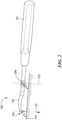
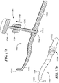
- FIG. 1 depicts an illustrative embodiment of a microfracture pick 100, in accordance with the subject application.
- the microfracture pick 100 has a proximal portion that includes an elongated handle 102, and a distal portion that includes a generally elongated shaft 104, which has a proximal end 110 and a distal end 112.
- the handle 102 is coupled to the proximal end 110 of the shaft 104.
- the microfracture pick 100 further includes a sharp, angled tip 106 located at the distal end 112 of the shaft 104, and an engaging feature 108 disposed at a fixed location on the shaft 104 for engaging a complementary feature 114 of a strike instrument 101.
- the strike instrument 101 can include a shaft 116 that has a proximal end 118 and a distal end 120, and the complementary feature 114 can be located at the distal end 120 of the shaft 116.
- the strike instrument 101 can further include a handle 122 having a proximal end 124 and a distal end 126 coupled to the proximal end 118 of the shaft 116, and an impact surface 128 located at the proximal end 124 of the handle 122.
- the handle 122, the shaft 116, and the impact surface 128 of the strike instrument 101 can be implemented as a single component.
- the handle 102 and the shaft 104 of the microfracture pick 100 can be implemented as a single component.
- the shaft 104 of the microfracture pick 100, as well as the shaft 116 of the strike instrument 101 can be made from machined medical grade material such as hardened stainless steel, or any other suitable material.
- the handle 102 of the microfracture pick 100, as well as the handle 122 of the strike instrument 101 can have a cylindrical shape, or any other suitable shape.
- the tip 106 is bent at an angle of about 20°, 40°, 60°, 90°, or any other suitable angle, relative to the longitudinal axis 142 of the microfracture pick 100.
- the tip 106 can be optionally bent at an angle greater than 90° relative to the longitudinal axis 142 by bending the tip 106 back toward the handle 102.
- the direction 133 of the sharp tip 106 of the microfracture pick 100 can be aligned at an angle ⁇ relative to a surface 130 (see FIG. 1 ), which can correspond to the surface of bone.
- a surface 130 see FIG. 1
- the longitudinal axis 132 the strike instrument 101 can be aligned at about the same angle ⁇ relative to the surface 130. Accordingly, when a user (e.g., a surgeon) strikes the impact surface 128 of the strike instrument 101 with a hammer, mallet, or any other suitable striking implement, a force 134 is produced that is translated via the shaft 104 of the microfracture pick 100 through the tip 106.
- FIG. 2 depicts a perspective view of the microfracture pick 100, including the handle 102, the shaft 104, the sharp, angled tip 106, and the engaging feature (see reference numeral 108; FIG. 1 ), which is configured as a receptacle 208.
- the complementary feature 114 of the strike instrument 101 (see FIG. 1 ) is configured to operatively engage the receptacle 208 of the microfracture pick 100.
- the surgeon can insert the complementary feature 114 of the strike instrument 101 into the receptacle 208 of the microfracture pick 100, and strike the impact surface 128 of the strike instrument 101 one or more times with a hammer or mallet to produce a force, thereby facilitating advancement of the tip 106 through the bone.
- FIG. 3 depicts a perspective view illustrating the microfracture pick 100 and the strike instrument 101, in which the complementary feature (see reference numeral 114; FIG. 1 ) is configured to include an optional nub 317 that can be temporarily or permanently fixated to the receptacle 208 of the microfracture pick 100.
- the optional nub 317, or an end of the shaft 116 without the nub 317 can be temporarily or permanently fixated to the receptacle 208 by way of threading, a press fit, a lever lock, a cam lock, a snap fit, a set screw, a taper fit, a luer lock (with or without taper), or any other suitable mechanism.
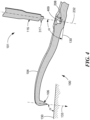
- FIG. 4 depicts a sectional view illustrating the microfracture pick 100 including the receptacle 208, as well as the strike instrument 101 including the optional nub 317.
- the receptacle 208 is illustrated as being substantially internal to the shaft 104 of the microfracture pick 100.
- the nub 317 can be configured as a male connector or as a female connector and the receptacle 208 can be configured as a female connector or as a male connector.
- the microfracture pick 100 can be configured to include a male connector
- the strike instrument 101 can be configured to include a female connector for engaging the male connector of the microfracture pick 100.
- Such male and female connectors can be temporarily or permanently fixated to one another by way of threading, a press fit, a lever lock, a cam lock, a snap fit, a set screw, a taper fit, a luer lock (with or without taper), or any other suitable mechanism.
- the receptacle 208 can be configured to include an external drain hole 409 for sterilization and/or dry time purposes, as well as for avoiding a possible build-up of fluid in the receptacle 208 during use.
- the external drain hole 409 can have a diameter of about 2 mm, or any other suitable diameter.
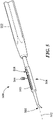
- FIG. 5 depicts an alternative embodiment of a microfracture pick 500 that includes a handle 502, a shaft 504, a sharp, angled tip 506, and an engaging feature 508.
- the shaft 504 is configured to incorporate a channel 540 along at least a portion of its length
- the engaging feature 508 is configured to engage and slide along the channel 540 to a desired location on the shaft 504.
- the channel 540 is substantially parallel to the longitudinal axis 542 of the shaft 504.
- the engaging feature 508 can be configured to include a receptacle like the receptacle 208 of FIG. 2 .
- the engaging feature 508 can be temporarily or permanently fixated at that location on the shaft 504 by at least one stop member 544, which, as shown in FIG. 5 , can be inserted into or otherwise engaged with the channel 540 adjacent the engaging feature 508, or by any other suitable mechanism.
- the engaging feature 508 can be temporarily or permanently fixated at a desired location on the shaft 504.
- the engaging feature 508 can be removed if it is not required to perform the microfracture procedure.
- FIG. 6 depicts another alternative embodiment of a microfracture pick 600 that includes a handle 602, a shaft 604, a sharp, angled tip 606, and a plurality of engaging features 608.1, 608.2, 608.3 disposed at a plurality of fixed locations, respectively, on the shaft 604.
- FIG. 6 depicts three (3) such engaging features on the shaft 604 for purposes of illustration.
- the microfracture pick 600 can include any suitable number of engaging features disposed at respective locations on the shaft 604.
- each of the plurality of engaging features 608.1, 608.2, 608.3 can be configured to include a receptacle like the receptacle 208 of FIG. 2 .
- a strike instrument 601 in which the complementary feature is configured to include an optional nub 617 at an end of a shaft 616 that can be temporarily or permanently fixated to a selected one of the plurality of engaging features 608.1, 608.2, 608.3 on the shaft 604.
- the optional nub 617, or the end of the shaft 616 without the nub 617 can be temporarily or permanently fixated to the selected engaging feature 608.1, 608.2, or 608.3 by way of threading, a press fit, a lever lock, a cam lock, a snap fit, a set screw, a taper fit, a luer lock (with or without taper), or any other suitable mechanism.
- FIG. 7 depicts an alternative embodiment of a strike instrument 701, which includes a complementary feature 714 for engaging an engaging feature 708 of a microfracture pick 700.
- the strike instrument 701 includes a handle 722 having a proximal end 711, a distal end 713, and a hole 719 located near the distal end 713 of the handle 722.
- the strike instrument 701 further includes a strike pin 715 configured to pass snugly through the hole 719, the complementary feature 714 located at one end of the strike pin 715, and an impact surface 728 located at the other end of the strike pin 715.
- the handle 722, the strike pin 715, and the impact surface 728 of the strike instrument 701 can be implemented as a single component.
- the microfracture pick 700 includes a handle 702, a shaft 704, the engaging feature 708 located on the shaft 704, and a sharp, angled tip 706 located at a distal end of the shaft 704. It is noted that the strike pin 715 can be temporarily or permanently fixated in the hole 719 through the handle 722 of the strike instrument 701.
- FIG. 8 depicts the microfracture pick 700 and the strike instrument 701, in which the complementary feature 714 of the strike instrument 701 is configured to include an optional nub 717, and the engaging feature 708 of the microfracture pick 700 is configured to include a receptacle 709.
- the optional nub 717, or an end of the strike pin 715 without the nub 717 can be temporarily or permanently fixated to the receptacle 709 of the microfracture pick 700 by way of threading, a press fit, a lever lock, a cam lock, a snap fit, a set screw, a taper fit, a luer lock (with or without taper), or any other suitable mechanism.
- the handle 722 of the strike instrument 701 can be temporarily or permanently fixated to the handle 702 of the microfracture pick 700 substantially parallel to its longitudinal axis 742, thereby allowing the surgeon to hold both the handle 722 of the strike instrument 701 and the handle 702 of the microfracture pick 700 with the same hand.
- the handle 722 of the strike instrument 701 can be temporarily or permanently fixated to the handle 702 of the microfracture pick 700 by way of threading, a press fit, a lever lock, a cam lock, a snap fit, a set screw, a taper fit, a luer lock (with or without taper), a bayonet mount, or any other suitable mechanism.
- the strike pin 715 can pass through the hole 719 in the handle 722 to engage the nub 717 of the strike instrument 701 with the receptacle 709 of the microfracture pick 700. Accordingly, if the surgeon experiences difficulties advancing the tip 706 of microfracture pick 700 through bone, he or she can strike the impact surface 728 of the strike pin 715 one or more times with a hammer or mallet to produce a force 734, thereby facilitating advancement of the tip 706 through the bone.
- the microfracture pick could include a receptacle on its shaft
- the strike instrument could include an optional nub on its shaft for engaging the receptacle.
- the microfracture pick can include at least one engaging feature configured like a nub at a fixed or movable location on its shaft
- the strike instrument can include at least one complementary feature configured like a receptacle on its shaft.
- such a receptacle on the shaft of the strike instrument can have a forked configuration for cradling the nub on the shaft of the microfracture pick.
- the microfracture pick can alternatively include a nub or receptacle, such as a male or female connector, on its handle for engaging a complementary feature on the strike instrument.
- the strike instrument can alternatively include a nub or receptacle, such as a male or female connector, on its handle for complementarily engaging an engaging feature on the microfracture pick.
- the microfracture pick could include a plurality of engaging features disposed at respective locations on its shaft for engaging a complementary feature of the strike instrument.
- the plurality of engaging features of the microfracture pick can be configured as respective receptacles having parallel or non-parallel axes.
- the plurality of engaging features of the microfracture pick can each be configured to accept a different configuration of the complementary feature of the strike instrument.
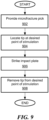
- the method includes providing a microfracture pick having a shaft with a proximal end and a distal end, an angled tip disposed at the distal end of the shaft, a handle coupled to the proximal end of the shaft, and at least one engaging feature disposed at one or more locations on the shaft for engaging a complementary feature of a strike instrument.
- the tip is located at a desired point of stimulation. For example, while locating the tip at the desired point of stimulation, at least a portion of the shaft may be inserted into an arthroscopic cannula.
- an impact surface of the strike instrument is struck by a hammer or mallet to produce a force that is translated via the shaft through the tip at the desired point of stimulation.
- the tip is then removed from the desired point of stimulation.
- FIGS. 10-18 depict further alternative embodiments of the disclosed microfracture pick and strike instrument.
- FIG. 10 depicts a microfracture pick 1000 and a strike instrument 1001 that are configured and arranged as a singular component.
- the microfracture pick 1000 includes a handle 1002, a shaft 1004, and an angled tip 1006 located at a distal end of the shaft 1004.
- the strike instrument 1001 includes a strike pin 1015, and an impact surface 1028 located at one end of the strike pin 1015. Because the microfracture pick 1000 and the strike instrument 1001 are configured and arranged as a singular component, the strike pin 1015 can provide a fixed strike zone for the microfracture pick 1000. It is noted that, in the singular component configuration of FIG.
- the longitudinal axis 1032 of the strike pin 1015 may be parallel or non-parallel with respect to the direction 1033 of the tip 1006.
- one or more strike zones for the microfracture pick 1000 may be provided at various locations and/or angles on either the shaft 1004 or the handle 1002 of the microfracture pick 1000.
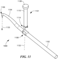
- FIG. 11 depicts a strike instrument 1101 that includes a forked complementary feature 1114 for engaging an engaging feature 1108 of a microfracture pick 1100.
- the microfracture pick 1100 further includes a handle 1102, a shaft 1104, and an angled tip 1106 located at a distal end of the shaft 1104.
- the strike instrument 1101 further includes a strike pin 1115, and an impact surface 1128 located at one end of the strike pin 1115.
- the forked feature 1114 of the strike instrument 1101 may have two prongs, as shown, or any other suitable number of prong(s).
- the strike instrument 1101 may include a complementary feature for engaging a forked engaging feature of the microfracture pick 1100. It is noted that the longitudinal axis 1132 of the strike pin 1115 may be parallel or non-parallel with respect to the direction 1133 of the tip 1106.
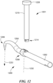
- FIG. 12 depicts a strike instrument 1201 that includes a T-shaped (or other similarly shaped) "male” complementary feature 1214 for engaging a slotted “female” engaging feature 1208 of a microfracture pick 1200.
- the microfracture pick 1200 further includes a handle 1202, a shaft 1204, and an angled tip 1206 located at a distal end of the shaft 1204.
- the strike instrument 1201 further includes a strike pin 1215, and an impact surface 1228 located at one end of the strike pin 1215.
- the strike instrument 1201 may include a slotted "female” complementary feature for engaging a T-shaped (or other similarly shaped) "male” engaging feature of the microfracture pick 1200. It is noted that the longitudinal axis 1232 of the strike pin 1215 may be parallel or non-parallel with respect to the direction 1233 of the tip 1206.
- FIG. 13 depicts a strike instrument 1301 that includes a threaded "male” complementary feature 1314 for engaging a threaded "female” engaging feature 1308 of a microfracture pick 1300.
- the microfracture pick 1300 further includes a handle 1302, a shaft 1304, and an angled tip 1306 located at a distal end of the shaft 1304.
- the strike instrument 1301 further includes a strike pin 1315, and an impact surface 1328 located at one end of the strike pin 1315.
- the strike instrument 1301 may include a threaded "female” complementary feature for engaging a threaded "male” engaging feature of the microfracture pick 1300.
- the threaded "male” complementary feature 1314 and the threaded "female” engaging feature 1308 may be configured to provide a quarter turn, luer lock, or any other suitable engagement. It is noted that the longitudinal axis 1332 of the strike pin 1315 may be parallel or non-parallel with respect to the direction 1333 of the tip 1306.
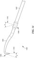
- FIG. 14 depicts a microfracture pick 1400 that includes a handle 1402, a shaft 1404, an angled tip 1406 located at a distal end of the shaft 1404, and an engaging feature 1408 configured to engage a complementary feature (not shown) of a strike instrument.
- the angle of the tip 1406 can vary within any suitable range of an angle ⁇ . In one embodiment, the angle ⁇ can be greater than 90°.
- the strike instrument can engage the engaging feature 1408 at any suitable angle ⁇ .
- the strike instrument can be used to generate a force along its longitudinal axis 1432, within a range of the angle y, either parallel to the direction 1433 of the tip 1406 or non-parallel with respect to the tip 1406, thereby avoiding potential interference with a portion of a patient's anatomy.
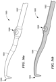
- FIG. 15a depicts a microfracture pick 1500 that includes a handle 1502, a shaft 1504, an angled tip 1506 located at a distal end of the shaft 1504, and an engaging feature 1508 configured to engage a complementary feature (not shown) of a strike instrument.
- the angle of the tip 1506 can vary within any suitable range of an angle ⁇ (see FIG. 15a ), as well as within any suitable range of an angle ⁇ a ( FIG. 15b ).
- the strike instrument can engage the engaging feature 1508 at any suitable angle ⁇ (see FIG. 15a ), as well as any suitable angle ⁇ a (see FIG. 15b ).
- the strike instrument can be used to generate a force along its longitudinal axis 1532, within respective ranges of the angle ⁇ and/or the angle ⁇ a , either parallel to the direction 1533 of the tip 1506 or non-parallel with respect to the tip 1506, thereby allowing improved access to various anatomies.
- FIG. 16a depicts a microfracture pick 1600 that includes a handle 1602, a shaft 1604, an angled tip 1606 located at a distal end of the shaft 1604, and an engaging feature 1608 configured to engage a complementary feature (not shown) of a strike instrument.
- FIG. 16b depicts a sectional view of the microfracture pick 1600 of FIG. 16a .
- the engaging feature 1608 can be configured as a ball type feature that allows the complementary feature of the strike instrument, such as a ball swivel feature, to float or rotate within the ball type feature of the microfracture pick 1600.
- the engaging feature 1608 configured as the ball type feature may not be entirely round, but may be partially rounded to limit the movement of the strike instrument in one or more directions.
- the engaging feature 1608 may be disk shaped, or any other suitable rounded or partially rounded shape.
- the complementary feature of the strike instrument may be configured as a ball type feature
- the engaging feature 1608 of the microfracture pick 1600 may be configured as a ball swivel feature.
- FIG. 17a depicts a sectional view of a strike instrument 1701 that includes a complementary feature 1714 for engaging an engaging feature 1708 of a microfracture pick 1700.
- the microfracture pick 1700 further includes a handle 1702, a shaft 1704, and an angled tip 1706 located at a distal end of the shaft 1704.
- the strike instrument 1701 further includes a strike pin 1715, and an impact surface 1791 located at one end of the strike pin 1715.
- the strike instrument 1701 is configured to engage with the microfracture pick 1700, and to be used in a reverse motion (as indicated by directional arrow 1795) to facilitate perforation of various anatomies. As shown in FIG.
- the strike instrument 1701 can include a slap hammer feature 1790 and/or the impact surface 1791 for striking with a mallet.
- the engaging feature 1708 can be configured to include a C-shaped opening for easy access.
- FIG. 18 depicts a strike instrument 1801 that includes a complementary feature 1814 suitably configured for engaging an engaging feature 1808 of a microfracture pick 1800.
- the microfracture pick 1800 further includes a handle 1802, a shaft 1804, and an angled tip 1806 located at a distal end of the shaft 1804.
- the strike instrument 1801 further includes a handle 1803, a shaft 1805, and a strike zone 1807 located on the shaft 1805 for striking with a mallet.
- the complementary feature 1814 of the strike instrument 1801 can be configured to engage with the engaging feature 1808 of the microfracture pick 1800 at any suitable angle.
- microfracture pick have been described for use in the context of resurfacing cartilage surfaces, they can also be used for perforating the subchondral bone in the subtalar/talus space (ankle) in arthrodesis procedures.
- a surgeon typically removes the cartilage on both the subtalar bone and the talus bone, and uses the microfracture pick to perforate the subtalar and talus bones in multiple places to promote bleeding.
- a screw is then delivered between the subtalar and talus bones to fuse the two bones together.
Landscapes
- Health & Medical Sciences (AREA)
- Surgery (AREA)
- Life Sciences & Earth Sciences (AREA)
- Biomedical Technology (AREA)
- Medical Informatics (AREA)
- Orthopedic Medicine & Surgery (AREA)
- Oral & Maxillofacial Surgery (AREA)
- Engineering & Computer Science (AREA)
- Dentistry (AREA)
- Heart & Thoracic Surgery (AREA)
- Nuclear Medicine, Radiotherapy & Molecular Imaging (AREA)
- Molecular Biology (AREA)
- Animal Behavior & Ethology (AREA)
- General Health & Medical Sciences (AREA)
- Public Health (AREA)
- Veterinary Medicine (AREA)
- Surgical Instruments (AREA)
- Orthopedics, Nursing, And Contraception (AREA)
Applications Claiming Priority (2)
| Application Number | Priority Date | Filing Date | Title |
|---|---|---|---|
| US201361781215P | 2013-03-14 | 2013-03-14 | |
| PCT/US2014/022537 WO2014150193A1 (en) | 2013-03-14 | 2014-03-10 | Microfracture pick |
Publications (2)
| Publication Number | Publication Date |
|---|---|
| EP2967586A1 EP2967586A1 (en) | 2016-01-20 |
| EP2967586B1 true EP2967586B1 (en) | 2023-03-01 |
Family
ID=50382746
Family Applications (1)
| Application Number | Title | Priority Date | Filing Date |
|---|---|---|---|
| EP14713009.0A Active EP2967586B1 (en) | 2013-03-14 | 2014-03-10 | Microfracture pick |
Country Status (10)
| Country | Link |
|---|---|
| EP (1) | EP2967586B1 (ja) |
| JP (2) | JP6473439B2 (ja) |
| CN (1) | CN105025822B (ja) |
| AU (1) | AU2014237438B2 (ja) |
| BR (1) | BR112015022177A2 (ja) |
| CA (1) | CA2903019A1 (ja) |
| MX (1) | MX2015011810A (ja) |
| RU (1) | RU2015142875A (ja) |
| WO (1) | WO2014150193A1 (ja) |
| ZA (1) | ZA201506162B (ja) |
Families Citing this family (4)
| Publication number | Priority date | Publication date | Assignee | Title |
|---|---|---|---|---|
| JP2021529066A (ja) | 2018-07-03 | 2021-10-28 | ボソニック・アクチェンゲゼルシャフトBosonic Ag | 高密度の骨層を穿孔するための装置 |
| JP6781495B1 (ja) * | 2020-05-15 | 2020-11-04 | 株式会社メドメタレックス | 薄刃のみシステム |
| CN112826565A (zh) * | 2020-12-31 | 2021-05-25 | 青岛市市立医院 | 一种穿透更有效的微骨折镐 |
| CN115300039A (zh) * | 2022-08-19 | 2022-11-08 | 浙江天松医疗器械股份有限公司 | 一种微骨折器 |
Family Cites Families (12)
| Publication number | Priority date | Publication date | Assignee | Title |
|---|---|---|---|---|
| US4979574A (en) * | 1985-09-30 | 1990-12-25 | Lalama Craig R | Punch tool apparatus and method |
| US5312413A (en) * | 1991-07-17 | 1994-05-17 | Eaton Alexander M | Instrumentation for ophthalmic surgery and method of using the same |
| JP3297042B1 (ja) * | 2001-08-20 | 2002-07-02 | 輝夫 伊藤 | 口腔インプラント治療用骨のみ |
| US6991633B2 (en) * | 2001-10-10 | 2006-01-31 | Codman & Shurtleff, Inc. | Rongeur with detachable crossbar |
| US6960214B2 (en) * | 2002-10-15 | 2005-11-01 | Zimmer Austin, Inc. | Method for performing automated microfracture |
| JP5154537B2 (ja) * | 2006-03-15 | 2013-02-27 | スミス アンド ネフュー インコーポレーテッド | 微小破壊ピック |
| US20100191195A1 (en) * | 2006-10-08 | 2010-07-29 | Ira Kirschenbaum | Cannulated apparatus and method relating to microfracture and revascularization methodologies |
| WO2009129272A2 (en) * | 2008-04-15 | 2009-10-22 | Lonnie Paulos | Tissue microfracture apparatus and methods of use |
| AU2010278867B2 (en) * | 2009-07-30 | 2015-10-01 | Smith & Nephew, Inc. | Instrument for creating microfractures in a bone |
| US20120071876A1 (en) * | 2010-09-17 | 2012-03-22 | Stoll E Jordan | Microfracture awl |
| US8721648B2 (en) * | 2011-05-13 | 2014-05-13 | Biomet Manufacturing, Llc | Microfracture pick for femoral head |
| EP2806806B1 (en) * | 2012-01-29 | 2019-04-10 | Smith & Nephew, Inc | Microfracture pick |
-
2014
- 2014-03-10 AU AU2014237438A patent/AU2014237438B2/en not_active Expired - Fee Related
- 2014-03-10 MX MX2015011810A patent/MX2015011810A/es unknown
- 2014-03-10 JP JP2016500993A patent/JP6473439B2/ja active Active
- 2014-03-10 WO PCT/US2014/022537 patent/WO2014150193A1/en active Application Filing
- 2014-03-10 CA CA2903019A patent/CA2903019A1/en not_active Abandoned
- 2014-03-10 BR BR112015022177A patent/BR112015022177A2/pt not_active IP Right Cessation
- 2014-03-10 EP EP14713009.0A patent/EP2967586B1/en active Active
- 2014-03-10 RU RU2015142875A patent/RU2015142875A/ru not_active Application Discontinuation
- 2014-03-10 CN CN201480015126.4A patent/CN105025822B/zh active Active
-
2015
- 2015-08-24 ZA ZA2015/06162A patent/ZA201506162B/en unknown
-
2018
- 2018-12-25 JP JP2018240952A patent/JP2019063582A/ja active Pending
Also Published As
| Publication number | Publication date |
|---|---|
| EP2967586A1 (en) | 2016-01-20 |
| JP2019063582A (ja) | 2019-04-25 |
| AU2014237438A1 (en) | 2015-09-17 |
| CN105025822B (zh) | 2018-11-23 |
| WO2014150193A1 (en) | 2014-09-25 |
| BR112015022177A2 (pt) | 2017-07-18 |
| RU2015142875A (ru) | 2017-04-18 |
| JP6473439B2 (ja) | 2019-02-20 |
| AU2014237438B2 (en) | 2018-11-29 |
| JP2016511099A (ja) | 2016-04-14 |
| ZA201506162B (en) | 2017-03-29 |
| CN105025822A (zh) | 2015-11-04 |
| CA2903019A1 (en) | 2014-09-25 |
| MX2015011810A (es) | 2016-08-11 |
Similar Documents
| Publication | Publication Date | Title |
|---|---|---|
| US9259230B2 (en) | Microfracture pick | |
| US9895179B2 (en) | Intramedullary fixation devices | |
| EP2806806B1 (en) | Microfracture pick | |
| US8409250B2 (en) | Meniscal repair system and method | |
| US7942881B2 (en) | Microfracture pick | |
| US7837713B2 (en) | Methods and surgical kits for minimally-invasive facet joint fusion | |
| US9357985B2 (en) | Method for accessing a spinal facet joint | |
| US9655630B2 (en) | Methods and devices for forming holes in bone to stimulate bone growth | |
| JP2019063582A (ja) | マイクロフラクチャーピック |
Legal Events
| Date | Code | Title | Description |
|---|---|---|---|
| PUAI | Public reference made under article 153(3) epc to a published international application that has entered the european phase |
Free format text: ORIGINAL CODE: 0009012 |
|
| 17P | Request for examination filed |
Effective date: 20151014 |
|
| AK | Designated contracting states |
Kind code of ref document: A1 Designated state(s): AL AT BE BG CH CY CZ DE DK EE ES FI FR GB GR HR HU IE IS IT LI LT LU LV MC MK MT NL NO PL PT RO RS SE SI SK SM TR |
|
| AX | Request for extension of the european patent |
Extension state: BA ME |
|
| DAX | Request for extension of the european patent (deleted) | ||
| STAA | Information on the status of an ep patent application or granted ep patent |
Free format text: STATUS: EXAMINATION IS IN PROGRESS |
|
| 17Q | First examination report despatched |
Effective date: 20170208 |
|
| STAA | Information on the status of an ep patent application or granted ep patent |
Free format text: STATUS: EXAMINATION IS IN PROGRESS |
|
| GRAP | Despatch of communication of intention to grant a patent |
Free format text: ORIGINAL CODE: EPIDOSNIGR1 |
|
| STAA | Information on the status of an ep patent application or granted ep patent |
Free format text: STATUS: GRANT OF PATENT IS INTENDED |
|
| INTG | Intention to grant announced |
Effective date: 20220922 |
|
| RAP3 | Party data changed (applicant data changed or rights of an application transferred) |
Owner name: SMITH & NEPHEW, INC. |
|
| GRAS | Grant fee paid |
Free format text: ORIGINAL CODE: EPIDOSNIGR3 |
|
| GRAA | (expected) grant |
Free format text: ORIGINAL CODE: 0009210 |
|
| STAA | Information on the status of an ep patent application or granted ep patent |
Free format text: STATUS: THE PATENT HAS BEEN GRANTED |
|
| AK | Designated contracting states |
Kind code of ref document: B1 Designated state(s): AL AT BE BG CH CY CZ DE DK EE ES FI FR GB GR HR HU IE IS IT LI LT LU LV MC MK MT NL NO PL PT RO RS SE SI SK SM TR |
|
| REG | Reference to a national code |
Ref country code: GB Ref legal event code: FG4D |
|
| REG | Reference to a national code |
Ref country code: CH Ref legal event code: EP Ref country code: AT Ref legal event code: REF Ref document number: 1550474 Country of ref document: AT Kind code of ref document: T Effective date: 20230315 |
|
| REG | Reference to a national code |
Ref country code: DE Ref legal event code: R096 Ref document number: 602014086330 Country of ref document: DE |
|
| REG | Reference to a national code |
Ref country code: IE Ref legal event code: FG4D |
|
| PGFP | Annual fee paid to national office [announced via postgrant information from national office to epo] |
Ref country code: FR Payment date: 20230208 Year of fee payment: 10 |
|
| REG | Reference to a national code |
Ref country code: LT Ref legal event code: MG9D |
|
| P01 | Opt-out of the competence of the unified patent court (upc) registered |
Effective date: 20230526 |
|
| REG | Reference to a national code |
Ref country code: NL Ref legal event code: MP Effective date: 20230301 |
|
| PG25 | Lapsed in a contracting state [announced via postgrant information from national office to epo] |
Ref country code: RS Free format text: LAPSE BECAUSE OF FAILURE TO SUBMIT A TRANSLATION OF THE DESCRIPTION OR TO PAY THE FEE WITHIN THE PRESCRIBED TIME-LIMIT Effective date: 20230301 Ref country code: NO Free format text: LAPSE BECAUSE OF FAILURE TO SUBMIT A TRANSLATION OF THE DESCRIPTION OR TO PAY THE FEE WITHIN THE PRESCRIBED TIME-LIMIT Effective date: 20230601 Ref country code: LV Free format text: LAPSE BECAUSE OF FAILURE TO SUBMIT A TRANSLATION OF THE DESCRIPTION OR TO PAY THE FEE WITHIN THE PRESCRIBED TIME-LIMIT Effective date: 20230301 Ref country code: LT Free format text: LAPSE BECAUSE OF FAILURE TO SUBMIT A TRANSLATION OF THE DESCRIPTION OR TO PAY THE FEE WITHIN THE PRESCRIBED TIME-LIMIT Effective date: 20230301 Ref country code: HR Free format text: LAPSE BECAUSE OF FAILURE TO SUBMIT A TRANSLATION OF THE DESCRIPTION OR TO PAY THE FEE WITHIN THE PRESCRIBED TIME-LIMIT Effective date: 20230301 Ref country code: ES Free format text: LAPSE BECAUSE OF FAILURE TO SUBMIT A TRANSLATION OF THE DESCRIPTION OR TO PAY THE FEE WITHIN THE PRESCRIBED TIME-LIMIT Effective date: 20230301 |
|
| REG | Reference to a national code |
Ref country code: AT Ref legal event code: MK05 Ref document number: 1550474 Country of ref document: AT Kind code of ref document: T Effective date: 20230301 |
|
| PG25 | Lapsed in a contracting state [announced via postgrant information from national office to epo] |
Ref country code: SE Free format text: LAPSE BECAUSE OF FAILURE TO SUBMIT A TRANSLATION OF THE DESCRIPTION OR TO PAY THE FEE WITHIN THE PRESCRIBED TIME-LIMIT Effective date: 20230301 Ref country code: PL Free format text: LAPSE BECAUSE OF FAILURE TO SUBMIT A TRANSLATION OF THE DESCRIPTION OR TO PAY THE FEE WITHIN THE PRESCRIBED TIME-LIMIT Effective date: 20230301 Ref country code: NL Free format text: LAPSE BECAUSE OF FAILURE TO SUBMIT A TRANSLATION OF THE DESCRIPTION OR TO PAY THE FEE WITHIN THE PRESCRIBED TIME-LIMIT Effective date: 20230301 Ref country code: GR Free format text: LAPSE BECAUSE OF FAILURE TO SUBMIT A TRANSLATION OF THE DESCRIPTION OR TO PAY THE FEE WITHIN THE PRESCRIBED TIME-LIMIT Effective date: 20230602 Ref country code: FI Free format text: LAPSE BECAUSE OF FAILURE TO SUBMIT A TRANSLATION OF THE DESCRIPTION OR TO PAY THE FEE WITHIN THE PRESCRIBED TIME-LIMIT Effective date: 20230301 |
|
| PG25 | Lapsed in a contracting state [announced via postgrant information from national office to epo] |
Ref country code: SM Free format text: LAPSE BECAUSE OF FAILURE TO SUBMIT A TRANSLATION OF THE DESCRIPTION OR TO PAY THE FEE WITHIN THE PRESCRIBED TIME-LIMIT Effective date: 20230301 Ref country code: RO Free format text: LAPSE BECAUSE OF FAILURE TO SUBMIT A TRANSLATION OF THE DESCRIPTION OR TO PAY THE FEE WITHIN THE PRESCRIBED TIME-LIMIT Effective date: 20230301 Ref country code: PT Free format text: LAPSE BECAUSE OF FAILURE TO SUBMIT A TRANSLATION OF THE DESCRIPTION OR TO PAY THE FEE WITHIN THE PRESCRIBED TIME-LIMIT Effective date: 20230703 Ref country code: EE Free format text: LAPSE BECAUSE OF FAILURE TO SUBMIT A TRANSLATION OF THE DESCRIPTION OR TO PAY THE FEE WITHIN THE PRESCRIBED TIME-LIMIT Effective date: 20230301 Ref country code: CZ Free format text: LAPSE BECAUSE OF FAILURE TO SUBMIT A TRANSLATION OF THE DESCRIPTION OR TO PAY THE FEE WITHIN THE PRESCRIBED TIME-LIMIT Effective date: 20230301 Ref country code: AT Free format text: LAPSE BECAUSE OF FAILURE TO SUBMIT A TRANSLATION OF THE DESCRIPTION OR TO PAY THE FEE WITHIN THE PRESCRIBED TIME-LIMIT Effective date: 20230301 |
|
| REG | Reference to a national code |
Ref country code: CH Ref legal event code: PL |
|
| PG25 | Lapsed in a contracting state [announced via postgrant information from national office to epo] |
Ref country code: SK Free format text: LAPSE BECAUSE OF FAILURE TO SUBMIT A TRANSLATION OF THE DESCRIPTION OR TO PAY THE FEE WITHIN THE PRESCRIBED TIME-LIMIT Effective date: 20230301 Ref country code: IS Free format text: LAPSE BECAUSE OF FAILURE TO SUBMIT A TRANSLATION OF THE DESCRIPTION OR TO PAY THE FEE WITHIN THE PRESCRIBED TIME-LIMIT Effective date: 20230701 |
|
| REG | Reference to a national code |
Ref country code: BE Ref legal event code: MM Effective date: 20230331 |
|
| REG | Reference to a national code |
Ref country code: DE Ref legal event code: R097 Ref document number: 602014086330 Country of ref document: DE |
|
| PG25 | Lapsed in a contracting state [announced via postgrant information from national office to epo] |
Ref country code: LU Free format text: LAPSE BECAUSE OF NON-PAYMENT OF DUE FEES Effective date: 20230310 |
|
| PLBE | No opposition filed within time limit |
Free format text: ORIGINAL CODE: 0009261 |
|
| STAA | Information on the status of an ep patent application or granted ep patent |
Free format text: STATUS: NO OPPOSITION FILED WITHIN TIME LIMIT |
|
| PG25 | Lapsed in a contracting state [announced via postgrant information from national office to epo] |
Ref country code: MC Free format text: LAPSE BECAUSE OF FAILURE TO SUBMIT A TRANSLATION OF THE DESCRIPTION OR TO PAY THE FEE WITHIN THE PRESCRIBED TIME-LIMIT Effective date: 20230301 |
|
| REG | Reference to a national code |
Ref country code: IE Ref legal event code: MM4A |
|
| PG25 | Lapsed in a contracting state [announced via postgrant information from national office to epo] |
Ref country code: SI Free format text: LAPSE BECAUSE OF FAILURE TO SUBMIT A TRANSLATION OF THE DESCRIPTION OR TO PAY THE FEE WITHIN THE PRESCRIBED TIME-LIMIT Effective date: 20230301 Ref country code: MC Free format text: LAPSE BECAUSE OF FAILURE TO SUBMIT A TRANSLATION OF THE DESCRIPTION OR TO PAY THE FEE WITHIN THE PRESCRIBED TIME-LIMIT Effective date: 20230301 Ref country code: LI Free format text: LAPSE BECAUSE OF NON-PAYMENT OF DUE FEES Effective date: 20230331 Ref country code: IE Free format text: LAPSE BECAUSE OF NON-PAYMENT OF DUE FEES Effective date: 20230310 Ref country code: DK Free format text: LAPSE BECAUSE OF FAILURE TO SUBMIT A TRANSLATION OF THE DESCRIPTION OR TO PAY THE FEE WITHIN THE PRESCRIBED TIME-LIMIT Effective date: 20230301 Ref country code: CH Free format text: LAPSE BECAUSE OF NON-PAYMENT OF DUE FEES Effective date: 20230331 |
|
| 26N | No opposition filed |
Effective date: 20231204 |
|
| PG25 | Lapsed in a contracting state [announced via postgrant information from national office to epo] |
Ref country code: BE Free format text: LAPSE BECAUSE OF NON-PAYMENT OF DUE FEES Effective date: 20230331 |
|
| PGFP | Annual fee paid to national office [announced via postgrant information from national office to epo] |
Ref country code: DE Payment date: 20231229 Year of fee payment: 11 Ref country code: GB Payment date: 20240108 Year of fee payment: 11 |