EP2967412B1 - Auf einem elektromagnetischen feld basierendes tragbares biomessungs- und biobildgebungssystem - Google Patents
Auf einem elektromagnetischen feld basierendes tragbares biomessungs- und biobildgebungssystem Download PDFInfo
- Publication number
- EP2967412B1 EP2967412B1 EP14768372.6A EP14768372A EP2967412B1 EP 2967412 B1 EP2967412 B1 EP 2967412B1 EP 14768372 A EP14768372 A EP 14768372A EP 2967412 B1 EP2967412 B1 EP 2967412B1
- Authority
- EP
- European Patent Office
- Prior art keywords
- probe
- tissue
- biological tissue
- signal
- blood flow
- Prior art date
- Legal status (The legal status is an assumption and is not a legal conclusion. Google has not performed a legal analysis and makes no representation as to the accuracy of the status listed.)
- Active
Links
Images


Classifications
-
- A—HUMAN NECESSITIES
- A61—MEDICAL OR VETERINARY SCIENCE; HYGIENE
- A61B—DIAGNOSIS; SURGERY; IDENTIFICATION
- A61B5/00—Measuring for diagnostic purposes; Identification of persons
- A61B5/0033—Features or image-related aspects of imaging apparatus, e.g. for MRI, optical tomography or impedance tomography apparatus; Arrangements of imaging apparatus in a room
- A61B5/004—Features or image-related aspects of imaging apparatus, e.g. for MRI, optical tomography or impedance tomography apparatus; Arrangements of imaging apparatus in a room adapted for image acquisition of a particular organ or body part
-
- A—HUMAN NECESSITIES
- A61—MEDICAL OR VETERINARY SCIENCE; HYGIENE
- A61B—DIAGNOSIS; SURGERY; IDENTIFICATION
- A61B5/00—Measuring for diagnostic purposes; Identification of persons
- A61B5/02—Detecting, measuring or recording for evaluating the cardiovascular system, e.g. pulse, heart rate, blood pressure or blood flow
- A61B5/026—Measuring blood flow
- A61B5/0261—Measuring blood flow using optical means, e.g. infrared light
-
- A—HUMAN NECESSITIES
- A61—MEDICAL OR VETERINARY SCIENCE; HYGIENE
- A61B—DIAGNOSIS; SURGERY; IDENTIFICATION
- A61B5/00—Measuring for diagnostic purposes; Identification of persons
- A61B5/02—Detecting, measuring or recording for evaluating the cardiovascular system, e.g. pulse, heart rate, blood pressure or blood flow
- A61B5/026—Measuring blood flow
- A61B5/0265—Measuring blood flow using electromagnetic means, e.g. electromagnetic flowmeter
-
- A—HUMAN NECESSITIES
- A61—MEDICAL OR VETERINARY SCIENCE; HYGIENE
- A61B—DIAGNOSIS; SURGERY; IDENTIFICATION
- A61B5/00—Measuring for diagnostic purposes; Identification of persons
- A61B5/02—Detecting, measuring or recording for evaluating the cardiovascular system, e.g. pulse, heart rate, blood pressure or blood flow
- A61B5/026—Measuring blood flow
- A61B5/0295—Measuring blood flow using plethysmography, i.e. measuring the variations in the volume of a body part as modified by the circulation of blood therethrough, e.g. impedance plethysmography
-
- A—HUMAN NECESSITIES
- A61—MEDICAL OR VETERINARY SCIENCE; HYGIENE
- A61B—DIAGNOSIS; SURGERY; IDENTIFICATION
- A61B5/00—Measuring for diagnostic purposes; Identification of persons
- A61B5/05—Detecting, measuring or recording for diagnosis by means of electric currents or magnetic fields; Measuring using microwaves or radio waves
- A61B5/0507—Detecting, measuring or recording for diagnosis by means of electric currents or magnetic fields; Measuring using microwaves or radio waves using microwaves or terahertz waves
-
- A—HUMAN NECESSITIES
- A61—MEDICAL OR VETERINARY SCIENCE; HYGIENE
- A61B—DIAGNOSIS; SURGERY; IDENTIFICATION
- A61B5/00—Measuring for diagnostic purposes; Identification of persons
- A61B5/05—Detecting, measuring or recording for diagnosis by means of electric currents or magnetic fields; Measuring using microwaves or radio waves
- A61B5/053—Measuring electrical impedance or conductance of a portion of the body
-
- A—HUMAN NECESSITIES
- A61—MEDICAL OR VETERINARY SCIENCE; HYGIENE
- A61B—DIAGNOSIS; SURGERY; IDENTIFICATION
- A61B5/00—Measuring for diagnostic purposes; Identification of persons
- A61B5/05—Detecting, measuring or recording for diagnosis by means of electric currents or magnetic fields; Measuring using microwaves or radio waves
- A61B5/055—Detecting, measuring or recording for diagnosis by means of electric currents or magnetic fields; Measuring using microwaves or radio waves involving electronic [EMR] or nuclear [NMR] magnetic resonance, e.g. magnetic resonance imaging
-
- A—HUMAN NECESSITIES
- A61—MEDICAL OR VETERINARY SCIENCE; HYGIENE
- A61B—DIAGNOSIS; SURGERY; IDENTIFICATION
- A61B5/00—Measuring for diagnostic purposes; Identification of persons
- A61B5/72—Signal processing specially adapted for physiological signals or for diagnostic purposes
- A61B5/7235—Details of waveform analysis
- A61B5/7246—Details of waveform analysis using correlation, e.g. template matching or determination of similarity
-
- A—HUMAN NECESSITIES
- A61—MEDICAL OR VETERINARY SCIENCE; HYGIENE
- A61B—DIAGNOSIS; SURGERY; IDENTIFICATION
- A61B5/00—Measuring for diagnostic purposes; Identification of persons
- A61B5/72—Signal processing specially adapted for physiological signals or for diagnostic purposes
- A61B5/7271—Specific aspects of physiological measurement analysis
- A61B5/7278—Artificial waveform generation or derivation, e.g. synthesizing signals from measured signals
-
- A—HUMAN NECESSITIES
- A61—MEDICAL OR VETERINARY SCIENCE; HYGIENE
- A61B—DIAGNOSIS; SURGERY; IDENTIFICATION
- A61B5/00—Measuring for diagnostic purposes; Identification of persons
- A61B5/72—Signal processing specially adapted for physiological signals or for diagnostic purposes
- A61B5/7271—Specific aspects of physiological measurement analysis
- A61B5/7282—Event detection, e.g. detecting unique waveforms indicative of a medical condition
-
- A—HUMAN NECESSITIES
- A61—MEDICAL OR VETERINARY SCIENCE; HYGIENE
- A61B—DIAGNOSIS; SURGERY; IDENTIFICATION
- A61B2560/00—Constructional details of operational features of apparatus; Accessories for medical measuring apparatus
- A61B2560/04—Constructional details of apparatus
- A61B2560/0431—Portable apparatus, e.g. comprising a handle or case
-
- A—HUMAN NECESSITIES
- A61—MEDICAL OR VETERINARY SCIENCE; HYGIENE
- A61B—DIAGNOSIS; SURGERY; IDENTIFICATION
- A61B2576/00—Medical imaging apparatus involving image processing or analysis
- A61B2576/02—Medical imaging apparatus involving image processing or analysis specially adapted for a particular organ or body part
-
- A—HUMAN NECESSITIES
- A61—MEDICAL OR VETERINARY SCIENCE; HYGIENE
- A61B—DIAGNOSIS; SURGERY; IDENTIFICATION
- A61B5/00—Measuring for diagnostic purposes; Identification of persons
- A61B5/24—Detecting, measuring or recording bioelectric or biomagnetic signals of the body or parts thereof
- A61B5/316—Modalities, i.e. specific diagnostic methods
- A61B5/318—Heart-related electrical modalities, e.g. electrocardiography [ECG]
- A61B5/346—Analysis of electrocardiograms
- A61B5/349—Detecting specific parameters of the electrocardiograph cycle
- A61B5/352—Detecting R peaks, e.g. for synchronising diagnostic apparatus; Estimating R-R interval
-
- A—HUMAN NECESSITIES
- A61—MEDICAL OR VETERINARY SCIENCE; HYGIENE
- A61B—DIAGNOSIS; SURGERY; IDENTIFICATION
- A61B5/00—Measuring for diagnostic purposes; Identification of persons
- A61B5/72—Signal processing specially adapted for physiological signals or for diagnostic purposes
- A61B5/7271—Specific aspects of physiological measurement analysis
- A61B5/7285—Specific aspects of physiological measurement analysis for synchronizing or triggering a physiological measurement or image acquisition with a physiological event or waveform, e.g. an ECG signal
- A61B5/7289—Retrospective gating, i.e. associating measured signals or images with a physiological event after the actual measurement or image acquisition, e.g. by simultaneously recording an additional physiological signal during the measurement or image acquisition
Definitions
- the present invention relates generally to electromagnetic field-based bio-sensing and bio-imaging, and in particular, to a handheld probe-based electromagnetic field technology that allows clinicians to assess functional and pathological conditions of biological tissue on-line at the point of care
- the successful management of a fractured bone involves an understanding of the two major components of any limb segment. These two components are the osseous or boney element and the soft tissue elements. Soft tissue elements are the skin, muscle, nerve and vessels while osseous element includes only the bone. The diagnosis and evaluation of the boney component is obvious to the treating physician by radiographic studies. The accurate assessment of the soft tissue component of the injured limb segment remains a major deficiency in management of fractures. To date several methods; such as laser Doppler and transcutaneous oxygen tensions have been attempted but they have been no better than clinical judgment. None of these methods have correlated with outcome. Consequently there is an important need to develop a simple effective method of assessing soft tissue viability.
- soft tissue injury As this component is often the determinant of the final outcome.
- the soft tissues provide the blood supply for the bone to heal, provide the coverage for the bone and the muscles, nerves and vessels provide for a functional outcome following injury.
- the clinical problem exists with closed or open fractures as there is no method at the present to objectively evaluate soft tissue damage prior to surgical treatment.
- the surgical approach causes further damage to the soft tissues leading to necrosis, wound slough and infection. Consequently, surgeons require a method to accurately and objectively establish soft tissue viability so as to minimize the complication rate.
- associated injuries to the muscle such as a compartment syndrome and arterial disruption require soft tissue viability assessment to plan an appropriate management.
- a compartment syndrome occurs after an injury to an extremity when the obligatory muscle swelling becomes excessive. If the involved muscle is contained in an enclosed fascial space, this swelling will compromise arteriolar muscle blood flow leading to what has been called "a heart attack" of skeletal muscle.
- the issue of early diagnosis of compartment syndrome is very important, and is not limited to the management of fractures. The swollen limb without fracture is commonly seen and should be urgently assessed by orthopedic specialists. Undiagnosed compartment syndrome leads to muscle necrosis, contracture and irreversible neurological deficits. Extensive irreversible muscle damage can eventually result in sepsis or amputation. The incidence of complications is related to the speed in diagnosis and timing of fasciotomy.
- EMT electromagnetic tomography
- 3D three-dimensional
- 4D four-dimensional
- a device according to the invention is defined in independent claim 18.
- the handheld probe is a first probe
- the system further includes a second probe, connected to the control unit, that also irradiates an electromagnetic field.
- the second probe may manipulated around the biological object as it irradiates the electromagnetic field; the received electromagnetic field is analyzed in conjunction with other data to create an image, in at least two dimensions, of the biological object around which the probe is manipulated; the second probe is stationary relative to the biological object and to the first probe; and/or the second probe also receives an irradiated electromagnetic field, and wherein the second received electromagnetic field is also analyzed in conjunction with other data to create the image, in at least two dimensions, of the biological object around which the probes are manipulated.
- the probe includes a waveguide.
- the waveguide is a ceramic waveguide; and/or the waveguide is a rectangular waveguide.
- the probe includes a plurality of sensors whose positions are tracked by the tracking unit. In a further feature, the probe includes at least three sensors whose positions are tracked by the tracking unit.
- an electromagnetic signal is generated by a Vector Network Analyzer and travels through a cable to a probe placed on the biological object where the electromagnetic signal is used to generate the electromagnetic field that is irradiated into the biological object.
- the biological object is a human tissue.
- the received electromagnetic field is analyzed in conjunction with other data to create an image, in at least two dimensions, of the biological object around which the probe is manipulated.
- the tracking unit may be external to the handheld control unit.
- the tracking unit may be internal to the handheld control unit.
- an electromagnetic signal is generated by a Vector Network Analyzer and travels through a cable to a first probe where the electromagnetic signal is used to generate the electromagnetic field that is irradiated into the biological object, and wherein the irradiated electromagnetic field is scattered and/or reflected by the biological object and received by a second probe.
- the scattered and/or reflected electromagnetic field is captured by an antenna device within the second probe and analyzed by the handheld control unit to determine functional and/or pathological conditions of the biological object; and/or the scattered and/or reflected electromagnetic field above is captured by an antenna device within the second probe and analyzed by the handheld control unit to determine if there is blood flow reduction.
- the received electromagnetic field is analyzed in conjunction with other data to create an image, in at least two dimensions, of the biological object around which the probe is manipulated.
- the step of processing the combined first and second signals to assess the normalcy of the biological tissue is carried out at the handheld control unit.
- the step of combining at least a portion of the first signal with at least a portion of the second signal is carried out by a Doppler sub-block.
- the step of combining at least a portion of the first signal with at least a portion of the second signal is carried out by a directional coupler within the Doppler sub-block; the directional coupler is a dual direction coupler; the directional coupler includes a first port, a second port, and a third port such that the first signal is received at the first port, at least a portion of the first signal is provided from the first port to, and output from, the second port, the second signal is received at the second port after being scattered/reflected by the biological tissue, and a portion of the second signal that is received at the second port is coupled with the portion of the first signal and output from the third port; and/or the directional coupler further includes a fourth port such that the portion of the first signal is a first portion, and a second portion of the first signal is output from the fourth port
- the method includes a step of determining, via a tracking unit, the position of the handheld probe while the handheld probe is irradiating the first signal into the biological tissue.
- the step of receiving the irradiated signal after the irradiated signal is scattered/reflected by the biological tissue is carried out at an antenna in the handheld probe.
- the handheld probe is a first handheld probe, and wherein the step of receiving the irradiated signal after the irradiated signal is scattered/reflected by the biological tissue is carried out at a second handheld probe.
- the method further includes a step of determining, via a tracking unit, the position of the second handheld probe while the second handheld probe is receiving the irradiated signal after the irradiated signal is scattered/reflected by the biological tissue.
- the step of combining at least a portion of the first signal with at least a portion of the second signal includes generating, via a directional coupler, a forward coupling path and a reverse coupling path.
- the step of combining at least a portion of the first signal with at least a portion of the second signal includes amplifying each of the forward coupling path and the reverse coupling path; the forward coupling path is connected to a first power splitter and the reverse coupling path is connected to a second power splitter; a first output of the first power splitter is connected to a first mixer, wherein a second output of the first power splitter is connected to a second mixer, wherein a first output of the second power splitter is connected to the first mixer, wherein a second output of the second power splitter is connected to the second mixer; an output of the first mixer is connected to a low pass filter, and an output of the second mixer is connected to a low pass filter; an output of the first mixer is connected to an analog-to-digit
- a method of assessing status of a biological tissue includes irradiating an electromagnetic signal, via a probe, into a biological tissue; receiving the irradiated electromagnetic signal after the signal is scattered/reflected by the biological tissue; providing blood flow volume information pertaining to the biological tissue by way of a blood flow analyzer (350) to determine blood volume; analyzing the received signal based at least upon the provided blood flow volume information together with knowledge of electromagnetic signal differences in normal, suspicious, and abnormal tissue; using a dielectric properties reconstruction algorithm, reconstructing dielectric properties of the biological tissue based at least upon results of the analyzing step and upon blood flow information; and using a tissue properties reconstruction algorithm, reconstructing tissue properties of the biological tissue based at least in part upon results of the reconstructing step together with blood flow volume information; and outputting imaging of the dielectric properties of the tissue.
- the method further includes a preliminary step of determining whether the probe is in the vicinity of the biological tissue.
- the method further includes a step of providing an indication, via the probe, as to whether the probe is determined to be in the vicinity of the biological tissue; the step of determining whether the probe is in the vicinity of the biological tissue is based at least in part upon knowledge of electromagnetic signal differences in biological tissue, air, and a gel; the method further includes a preliminary step of obtaining the knowledge of electromagnetic signal differences in biological tissue, air, and a gel via one or more physical/biophysical experiment; and/or the step of determining whether the probe is in the vicinity of the biological tissue includes determining whether the probe is in physical contact with the biological tissue.
- receiving the irradiated electromagnetic signal includes receiving the irradiated electromagnetic signal at a probe.
- the probe via which the electromagnetic signal is irradiated is the same probe as the probe at which the irradiated electromagnetic signal is received; the probe via which the electromagnetic signal is irradiated is a different probe from the probe at which the irradiated electromagnetic signal is received; the method further includes a step of determining whether the probe at which the irradiated electromagnetic signal is received is in the vicinity of the biological tissue; the step of determining whether the probe at which the irradiated electromagnetic signal is received is in the vicinity of the biological tissue includes determining whether such probe is in physical contact with the biological tissue; the method further includes a step of determining, via a tracking unit, the position of the probe that receives the irradiated electromagnetic signal while the step of receiving is being carried out; the step of determining includes determining the position of a sensor disposed in the probe that receives the irradiated electromagnetic signal; the step
- the blood flow information is provided at least partly on the basis of a step of synchronizing the received electromagnetic signal with a signal representing a blood circulation cycle of the biological tissue.
- the blood flow information is provided at least partly on the basis of a step, after the synchronizing step, of processing the synchronized signals using coherent averaging; and/or the step of providing the blood flow information includes providing blood volume information.
- the irradiated electromagnetic signal is a first electromagnetic signal
- the received electromagnetic signal is a second electromagnetic signal
- the method further comprises a step of processing the first and second electromagnetic signals using a Doppler sub-block.
- the blood flow information is provided at least partly on the basis of a step of synchronizing an output of the Doppler sub-block with a signal representing a blood circulation cycle of the biological tissue; and/or the step of providing the blood flow information includes providing blood volume information.
- the step of analyzing the received signal includes a preliminary step of obtaining the knowledge of electromagnetic signal differences in normal, suspicious, and abnormal tissue during clinical procedures.
- the step of obtaining the knowledge of electromagnetic signal differences in normal, suspicious, and abnormal tissue during clinical procedures includes correlating information about a particular electromagnetic signal with information from one or more tissue pathological study.
- the step of reconstructing tissue properties of the biological tissue includes reconstructing cellular volume fraction ( VF cell ) .
- the step of reconstructing tissue properties of the biological tissue includes reconstructing intracellular conductivity ( ⁇ intracell ) .
- the step of reconstructing tissue properties of the biological tissue includes reconstructing extracellular conductivity ( ⁇ extracell ) .
- the method further includes a step, after the step of reconstructing tissue properties of the biological tissue, of conducting visualization, imaging and matching analysis.
- the step of conducting visualization, imaging and matching analysis is based at least in part upon results of the step of reconstructing dielectric properties of the biological tissue; dielectric property information based on frequency is an input to the step of conducting visualization, imaging and matching analysis; dielectric property information based on time is an input to the step of conducting visualization, imaging and matching analysis; the step of conducting visualization, imaging and matching analysis is based at least in part upon results of the step of reconstructing tissue properties of the biological tissue; cellular volume fraction ( VF cell ) is an input to the step of conducting visualization, imaging and matching analysis; intracellular conductivity ( ⁇ intracell ) is an input to the step of conducting visualization, imaging and matching analysis; extracellular conductivity ( ⁇ extracell ) is an input to the step of conducting visualization, imaging and matching analysis; the step of conducting visualization, imaging and matching analysis is based at least in part upon results of the step of analyzing the
- Another aspect is a method of imaging a biological tissue for identifying and locating tissue abnormalities, including: irradiating an electromagnetic signal, via a probe, in the vicinity of a biological tissue, the probe defining a transmitting probe; at a probe, receiving the irradiated electromagnetic signal after the signal is scattered/reflected by the biological tissue, the probe defining a receiving probe; providing blood flow information pertaining to the biological tissue; using a tissue properties reconstruction algorithm and blood flow information, reconstructing tissue properties of the biological tissue; determining, via a tracking unit, the position of at least one of the transmitting probe and the receiving probe while the step of receiving is being carried out, the at least one probe defining a tracked probe; and correlating the reconstructed tissue properties with the determined probe position so that tissue abnormalities can be identified and spatially located.
- the transmitting probe is the same probe as the receiving probe.
- the transmitting probe is a different probe from the receiving probe.
- the tracked probe includes both the transmitting probe and the receiving probe, all while the step of receiving is being carried out.
- the method further includes a preliminary step of determining whether the tracked probe is in the vicinity of the biological tissue.
- the method further includes a step of providing an indication, via the tracked probe, as to whether the tracked probe is determined to be in the vicinity of the biological tissue; the step of determining whether the tracked probe is in the vicinity of the biological tissue is based at least in part upon knowledge of electromagnetic signal differences in biological tissue, air, and a gel; the method further includes a preliminary step of obtaining the knowledge of electromagnetic signal differences in biological tissue, air, and a gel via one or more physical/biophysical experiment; and/or the step of determining whether the tracked probe is in the vicinity of the biological tissue includes determining whether the tracked probe is in physical contact with the biological tissue.
- the step of determining includes determining the position of a sensor disposed in the tracked probe. In further features, the step of determining includes determining the position of at least three sensors disposed within the tracked probe; and/or the at least three sensors are spatially separated within the tracked probe.
- the step of determining includes determining the position of the tracked probe in three dimensions.
- the step of determining includes determining the position of the tracked probe at multiple points in time.
- the method further includes a step of correlating the determined position of the tracked probe to known information about the position and contours of the biological tissue.
- the method further includes a surfacing process, carried out prior to the step of receiving the irradiated electromagnetic signal, wherein the position of the tracked probe, in at least two dimensions, is repeatedly determined as the tracked probe is placed in different locations against the surface of the biological tissue, thereby developing a digital map of the surface of the biological tissue that is subsequently used in the step of correlating the determined position to position and contours of the biological tissue; the method further includes a step of mapping the status of the tissue; the step of mapping the status of the tissue utilizes matching data from a database; the matching data in the database is based on previous experiments with animals and clinical studies with patients; and/or the method further includes a step of imaging the tissue.
- the blood flow information is provided at least partly on the basis of a step of synchronizing the received electromagnetic signal with a signal representing a blood circulation cycle of the biological tissue.
- the blood flow information is provided at least partly on the basis of a step, after the synchronizing step, of processing the synchronized signals using coherent averaging; and/or the step of providing the blood flow information includes providing blood volume information.
- the method further includes a step of analyzing the received signal based at least upon the provided blood flow information and upon knowledge of electromagnetic signal differences in normal, suspicious, and abnormal tissue.
- the method further includes a step of using a dielectric properties reconstruction algorithm, reconstructing dielectric properties of the biological tissue based at least upon results of the analyzing step and upon blood flow information; the step of reconstructing tissue properties is based at least in part upon results of the step of reconstructing dielectric properties and upon blood flow information;
- the step of analyzing the received signal includes a preliminary step of obtaining the knowledge of electromagnetic signal differences in normal, suspicious, and abnormal tissue during clinical procedures; and/or the step of obtaining the knowledge of electromagnetic signal differences in normal, suspicious, and abnormal tissue during clinical procedures includes correlating information about a particular electromagnetic signal with information from one or more tissue pathological study.
- the irradiated electromagnetic signal is a first electromagnetic signal
- the received electromagnetic signal is a second electromagnetic signal
- the method further comprises a step of processing the first and second electromagnetic signals using a Doppler sub-block.
- the blood flow information is provided at least partly on the basis of a step of synchronizing an output of the Doppler sub-block with a signal representing a blood circulation cycle of the biological tissue; the step of providing the blood flow information includes providing blood volume information; the step of providing the blood flow information includes providing blood velocity information; and/or the step of providing the blood flow information includes providing blood direction information.
- the step of reconstructing tissue properties of the biological tissue includes reconstructing cellular volume fraction ( VF cell ) .
- the step of reconstructing tissue properties of the biological tissue includes reconstructing intracellular conductivity ( ⁇ intracell ).
- the step of reconstructing tissue properties of the biological tissue includes reconstructing extracellular conductivity ( ⁇ extracell ).
- the step of correlating the reconstructed tissue properties with the determined probe position includes conducting visualization/imaging and matching analysis.
- dielectric property information based on frequency is an input to the step of conducting visualization/imaging and matching analysis;
- dielectric property information based on time is an input to the step of conducting visualization/imaging and matching analysis;
- cellular volume fraction ( VF cell ) is an input to the step of conducting visualization/imaging and matching analysis;
- intracellular conductivity ( ⁇ intracell ) is an input to the step of conducting visualization/imaging and matching analysis;
- extracellular conductivity ( ⁇ extracell ) is an input to the step of conducting visualization/imaging and matching analysis;
- the step of conducting visualization/imaging and matching analysis is based at least in part upon results of a step of analyzing the received signal based at least upon the provided blood flow information and upon knowledge of electromagnetic signal differences in normal, suspicious, and abnormal tissue;
- the step of conducting visualization/imaging and matching analysis is based at least in part upon results of the step of providing the blood flow information;
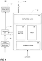
- FIG. 1 is a block diagram of a handheld electromagnetic field-based bio-sensing and bio-imaging (EMFBioSI) system 110 in accordance with a preferred embodiment of the present invention.
- the system 110 includes a handheld control unit 150, a handheld probe 164, an external electromagnetic field generator 112, and an external tracking unit 118.
- a power supply 122 which may include an AC/DC converter and one or more batteries, may be provided for the tracking unit 118.
- FIG. 2 is a perspective view of the handheld control unit 150 and probe 164 of the EMFBioSI system 110
- FIG. 3 is a block diagram of the control unit 150 of FIG. 1 .
- the control unit 150 includes a Doppler sub-block 170, a portable Vector Network Analyzer (VNA) (for example, Agilent FieldFox 2ports portable VNA) 156, a tablet computer 162, and a power sub-block 160.
- VNA Vector Network Analyzer
- the tablet computer 162 provides primary control, including a primary user interface, to a user.
- the tablet computer 162 is communicatively connected to the VNA 156, which generates EM signals having desired parameters, via a first communication link 169, and is likewise communicatively connected to the Doppler sub-block 170, which processes received signals after they have passed through an interrogation region, via a second communication link 171.
- the tablet computer 162 is also communicatively connected to the external tracking unit 118 via a third communication link 173.
- EM signals generated by the VNA 156 pass through the cable to the probe 164 and interrogate the tissue via irradiation.
- the EM signal reflected by or transmitted through the tissue passes back to VNA 156 through the probe and coaxial cable to the same port (or a second port, as described later) and the complex reflected or transmitted EM signal is measured by VNA, for example in form of amplitude and phase or in form of real and imaginary parts of the signal.
- VNA the complex reflected or transmitted EM signal irradiated from the first port, reflected by the sample and measured by the same first port is called S 11 .
- S 21 an EM signal irradiated from the second port, reflected by the sample and measured by the first port.
- S 21 an EM signal irradiated from the second port, reflected by the sample and measured by the first port.
- S ij The overall signal generated by port i and measured in port j after being affected by the sample. All of this is further discussed elsewhere herein.
- controlled EM signals generated by the VNA 156 are also provided to the Doppler sub-block 170 by a fourth communication link 152.
- the EM signal travels via a probe connection 168 to the probe 164.
- the probe connection 168 utilizes a high quality coaxial cable 168.
- the probe 164 both delivers the EM signals and receives them after they pass through or are reflected by the interrogation region. After being received by the VNA, they are processed by the Doppler sub-block 170, with the output being processed by an application on the tablet computer 162.
- FIG. 4 is a block diagram of the Doppler sub-block 170 used in the system 110.
- the Doppler sub-block 170 includes a dual direction coupler 172 having a forward coupling path 174 and a reverse coupling path 175.
- the output of the forward coupling path 174 is connected to a first amplifier 176, whose output is connected to a two-way 90° power splitter 178.
- the output of the reverse coupling path 175 is connected to a second amplifier 196 and then a third amplifier 197, whose output is connected to a two-way 0° power splitter 198.
- the outputs 179,180,199,200 of the power splitters 178,198 are connected to mixers 181,182 whose outputs 183,184 are connected to low pass filters 185,186.
- One device suitable for use as the mixers 181,182 is a Mini-Circuits ZFM.
- the output of each low pass filter 185,186 is connected to a respective amplifier and then to an analog-to-digital converter (ADC) 210, and the outputs 212,214 of the ADC 210 are connected to a digital signal processor 220.
- ADC analog-to-digital converter
- the EM signal from the VNA 156 is directed to the probe 164 through a dual direction coupler 172.
- the same EM signal passes through a forward coupling path 174, goes through an amplifier 176, and then passes through a two-way 90° power splitter 178 to obtain an in-phase signal on one output 179 and a quadrature phase signal on its other output 180.
- the EM signal from the VNA 156 is provided at a level of 0dBm (0.001W)
- the EM signal passing through the forward coupling path 174 is with power of -20 dBm (0.01 mW)
- the resulting signal is amplified by 30 dB to +10dBm(10 mW).
- FIG. 5 is a perspective view of the probe 164, of FIG. 1 used in the EMFBioSI system 110, being placed on a human arm 163.
- the EM signal 152 from the VNA 156 is received directly by the probe 164 through the coaxial cable 168.
- the probe 164 sends the signal into the tissue of the arm 163.
- a resulting signal is reflected and scattered by the tissue of the arm 163 back to the probe 164, where it is received and sent back to the control unit 150 via the coaxial cable 168.
- each received signal is sometimes referred to hereinafter as S jk , where the index j refers to the jth port of VNA 156, which has a probe connected to the port.
- the jth port generates the original electromagnetic signal and transmits it to a probe toward the interrogation zone.
- the index k refers to the kth port of the VNA 156 which in some embodiments has a probe connected to the port.
- the kth port via an antenna in the probe, receives or collects the reflected/scattered EM signal.
- Other embodiments may utilize more than one probe.
- two probes are utilized.
- other received signals may, for example, be designated as S 22 , S 21 , and S 12 .
- part of a reflected EM signal or field passes through the probe 164 and the cable into the dual direction coupler 172 where it is directed through the reverse coupling path 175.
- the output is passed through two amplifiers 196,197 and then through a two-way 0° power splitter 198 to obtain an in-phase signal on one output 199 and a quadrature phase signal on its other output 200.
- the reflected EM signal is received at the dual direction coupler 172 with power -50 dBm, and is amplified by 60dB and then +10dBm by the two amplifiers 196,197.
- the four signals carried by the respective outputs 179,180,199,200 from the power splitters 178,198 are now combined for analysis.
- the in-phase signal on the first output 179 of the two-way 90° power splitter 178, whose original source was the VNA 156, and the signal on the first output 199 of the two-way 0° power splitter 198, whose original source was the EM signal reflected and scattered by the tissue, are sent through a first mixer 181 (Mini-Circuits ZFM-2000) to produce an in-phase signal I _ out at its output 183.
- the quadrature signal on the second output 180 of the two-way 90° power splitter 178 whose original source was the VNA 156
- the signal on the second output 200 of the two-way 0° power splitter 198 whose original source was the EM signal reflected and scattered by the tissue
- I-Out and Q-Out are each routed through a respective low pass filter 185,186 and into the ADC 210, and the digitized signals on the ADC outputs 212,214 are provided to the DSP 220 or directly to a computer 162 for further signal analysis and processing.
- FIG. 6A is a perspective view of the probe 164 of FIG. 1 .
- FIG. 6B is an exploded perspective view of the probe of FIG. 6A , showing three position tracking sensors 166 and a waveguide 167.
- the waveguide is a rectangular waveguide.
- the spatial positions (x(t),y(t),z(t)) of each of the position tracking sensors 166 over time are tracked by the tracking unit 118.
- a suitable example of such a unit is the Aurora system by NDI, available at http://www.ndigital.com/medical.
- the probe 164 illustrated and described herein includes three sensors 166, it will be appreciated that other embodiments may use more than three sensors.
- the three position tracking sensors 166 are spatially separated within the probe 164 to allow for tracking the position (x(t),y(t),z(t)) of the probe head 165 during clinical study in relation to the surface of biological tissue 163.
- the position tracking sensors 166 are also used to track the angle at which the EM signal irradiated from the probe 164 interrogates the tissue. The information from these sensors 166 is needed in order to provide two-dimensional tissue surface mapping/imaging, as the signal location and angle should be known for both surfacing and proper image reconstruction.
- the core of the probe 164 includes a waveguide 167.
- a waveguide might be rectangular.
- the rectangular waveguide 167 is filled with a matching material that may be selected or designed such that its dielectric properties match the dielectric properties of biological tissues and to minimize the dimensions of the probe 164.
- a suitable matching material is a ceramic with ⁇ ⁇ 60 and low attenuation
- one suitable ceramic waveguide 167 may thus be constructed having dimensions of, for example, 21 x 7.5 x 53mm, which result in corresponding probe dimensions that are within a clinically acceptable range.
- Useful dielectric property information may be found in Gabriel S, Lau RW and Gabriel G 1996, "The dielectric properties of biological tissues: II. Measurements in the frequency range 10Hz to 20 GHz," Phys. Med. Biol. 41 2251-69 ("Gabriel").
- the lowest critical (cutoff) frequency is in dominant H 10 mode.
- Suitable ceramic waveguides may be made using a conventional three step manufacturing process. In a first step, a ceramic plate (in our exemplary case, with dimensions 53 x 21 x 7.5mm with desired hole) is made. This may be done using a proper furnace or the like to sinter a powder of so called parent compounds.
- the second step is the metallization of all surface of the ceramic plate except the one that is an EM irradiation surface and excitation hole. This might be done by applying a highly conductive (usually silver) paste and then heating.
- the third step is to connect the outer conductor of coaxial cable with one metallized surface and inner conductor with the opposite metallized surface through an excitation hole.
- the increased permeability of an EM waveguide is achieved at the first step of the manufacturing by mixing a powder of conventional parent compound (for example, a barium titanate (BaTi 4 O 9 or Ba 2 Ti 9 O 20 )) with a powder of magnetic materials of high permeability and small losses at microwave frequencies.
- a powder of conventional parent compound for example, a barium titanate (BaTi 4 O 9 or Ba 2 Ti 9 O 20 )
- Conventional ferrites for example, NiZn or MnZn
- the frequencies of our interest are near 1GHz. This frequency region is of great interest for various industrial applications of materials with high magnetic permeability, for example wireless communications and data storage.
- potential useful magnetic materials might include 1) nanocrystaline Fe-Co-Ni-B based material with effective magnetic permeability of about 500-600 at 1GHz region [4], Co-Fe-Zr-B or Co-Fe-Si-B; and/or 2) novel hexa-ferrites (with formula M(Fe 12 O 19 ), where M is usually barium Ba, strontium, Calcium Ca or Lead Pb) with complex permittivity and permeability that can vary with composition of materials and frequency.
- FIG. 7 is a flow diagram of the operational process 300 of the EMFBioSI system 110 of FIG. 1 in accordance with one or more preferred embodiments of the present invention.
- this process 300 utilizes a number of input signals, including S 11 , introduced in FIG. 4 ; an internal clock 314; the output of the Doppler sub-block 170, introduced in FIG. 4 ; sensor signals 318, and an electrocardiography (ECG) or plethysmography signal 116.
- ECG electrocardiography
- plethysmography signal 116 an electrocardiography
- the process 300 also utilizes additional data and other information, obtained or derived prior to operation and stored in a database or elsewhere in the system 110.
- Such information which serves as control data, includes material type information (control data) 310 pertaining to the how the characteristics of S 11 vary based on whether S 11 passes through tissue, air, or a gel, and tissue status information (control data) 312 pertaining to "normal,” “suspicious,” and “abnormal” characteristics of S 11 .
- material type information or control data 310 may be obtained via physical/biophysical experiments, while the tissue status information or control data 312 may be obtained during previous clinical procedures when a particular EM signal S 11 is correlated with tissue pathological studies.
- the material type control data 310 is used in a decision block 316 where it is determined whether the probe 164 is on biologic tissue 163 or not. In order to facilitate ease of use by the operator, an indication of whether the probe 164 is properly on the tissue 163 or not. Such an indication might include a green light, a beep, or the like. A corresponding indication when the probe 164 is not on the tissue, such as a red light, a buzzer, or the like, may also be provided.
- the material type control data 310 is also provided as an input to a filter 320. Once it is determined the probe is on tissue 163 and the signal is within a valid range to pass the filter 320, the signal is ready for complex S 11 signal analysis at block 326.
- This block 326 also requires input from the tissue status control data 312 and a blood flow analyzer 350.
- the tissue status control data which corresponds to the differences in the value of S 11 resulting from normal, suspicious, or abnormal tissue, is stored in a computer database and is compared on-line with a received EM signal S 11 . Correlation and cross-correlation analysis as well as pattern recognition methods may be used.
- the blood flow analyzer 350 is based on the use of a Doppler signal that has been processed using R-wave synchronization at block 340 and coherent averaging at block 342. This is explained as follows.
- a signal at Doppler frequency is small and comparable to noise.
- a coherent averaging process is used to detect a signal with amplitude, which is comparable or less than the amplitude of noise.
- the amplitude of random noise is decreased by a factor of N.
- the condition of coherent signals is achieved in at least some embodiments of the system 110 through synchronization 340, sometimes referred to herein as R-Wave synchronization (based on use of the "R" component of the QRS complex seen in a typical electrocardiogram), of the realizations of the Doppler signal 171 and blood circulation cycles as represented by electrocardiography (ECG) or plethysmography input signal 116.
- ECG electrocardiography
- the received Doppler signals 171, coherently averaged with respect to the circulation cycle are signals x(t) in the above equation example.
- Coherent averaging is possible as a result of the synchronization with the circulatory cycles (R-wave synchronization) that are provided by independently measured ECG or R-pulses or plethysmography, or by other means of synchronization with circulatory activity.
- the complex S 11 signal analysis is now performed at block 326 using the input from the tissue status control data 312, the filter 320, and the blood flow analyzer 350.
- the excitation frequency higher than the dominant mode
- different Transverse Electric (TE) and Transverse Magnetic (TM) modes will be excited. This also will change the polarization of the irradiated EM field.
- Blood flow volume information received from "Blood flow analyzer" block 350, is used in the "Complex S 11 Signal Analysis” 326 to assess the tissue related changes in S 11 .
- the frequency shift of the received Doppler signal 171 is proportional to the velocity/direction of the arterial blood flow, and the strength (or amplitude) of the signal is proportional to the volume of the flowing arterial blood.
- tissue dielectric properties reconstruction is performed at block 330.
- This reconstruction utilizes the measured EM signal S 11 information and results of the complex S 11 signal analysis 326, output from block 326; information about the volume of blood received from the blood flow analyzer 350; and a dielectric properties reconstruction algorithm 332.
- Blood volume with tabulated dielectric properties discussed in the Gabriel reference, is taken into account when assessing a tissue volume and its dielectric properties using multi-component dielectric mixture theory. See Landau L.D. and E.M. Lifshitz, Electrodynamics of Continuous Media, 2nd edition, Pergamon Press, Oxford, 1984 (“Landau”) for details on multi-component dielectric mixture theory.
- tissue properties such as cellular volume fraction ( VF cell ), intracellular conductivity ( ⁇ intracell ) , and extracellular conductivity ( ⁇ extracell ), are reconstructed in the dielectric properties analyzer 336.
- the tissue property reconstruction carried out by the dielectric properties analyzer 336 utilizes the bulk dielectric properties of tissue over frequency and time, obtained from tissue dielectric properties reconstruction at block 330; information received from the blood flow analyzer 350 about the volume of blood; and a tissue properties reconstruction algorithm 338. Again, blood volume with tabulated dielectric properties is taken into account when assessing a tissue volume and its dielectric properties using multi-component dielectric mixture theory.
- tissue properties reconstruction algorithms are found in Semenov S.Y., Simonova G.I., Starostin A.N., Taran M.G., Souvorov A.E., Bulyshev A.E., Svenson R.H., Nazarov A.G., Sizov Y.E., Posukh V.G., Pavlovsky A., Tatsis G.P., "Modeling of dielectrical properties of cellular structures in the radiofrequency and microwave spectrum/Electrically interacting vs non-interacting cells," Annals of Biomedical Engineering, 2001, 29, 5, 427-435 , and in Semenov S.Y., Svenson R.H., Bulyshev A.E., Souvorov A.E., Nazarov A.G., Sizov Y.E., Posukh V.G., Pavlovsky A., Tatsis G.P., "Microwave spectroscopy of myocardial ischemia and infarction
- a biological area of interest As a 3D surface in order to make space-time correlations between the actual position of the diagnostic probe at a particular time of the procedure and particular portions of a biological sample under the study. In at least some embodiments, this is achieved using a "surfacing" procedure 346 that is conducted during an initial phase of the clinical study of a biological area of interest.
- An operator may move the probe 164 in various ways along an area of assumed clinical interest while position determinations are conducted. For example, an operator may first move the probe along the assumed boundary of an area of clinical interest and second move the probe along two non-parallel lines inside an area of assumed clinical interest. Other movement patterns are likewise possible, such as by making continual lines or by placing the probe at different points.
- multiple position tracking sensors 166 may be physically attached directly to biological tissue in a similar manner, for example, the way that disposable ECG electrodes are conventionally attached to biological tissue.
- the positions of the sensors 166 are tracked or determined in three dimensions in the sensor tracking block 354 and analyzed so that the location and contours of the surface of biological tissue of clinical interest are known in two, or preferably three, dimensions and supplied in digital form into the "probe on tissue tracking" block 352.
- the positions of the sensors 166 continue to be tracked and compared to the known data regarding the surface of the tissue itself 163 so as to determine the position of the probe 164 on the tissue 163.
- the operational process 300 culminates at block 370 with visualization of the position of the probe on the object under study, imaging of dielectric and other properties (such as those described below and/or elsewhere herein) of the tissue, and matching analysis.
- multi-modal S 11 characteristics such as frequency, amplitude, and phase of S 11 signal, and polarization of E-field for each mode
- dielectric property information based on frequency and time from the tissue dielectric properties reconstruction at block 330
- tissue property information (such as VF cell , ⁇ intracell , and ⁇ extrace // ) from the dielectric properties analyzer 336
- blood flow information such as volume, velocity, and direction of blood flow from the blood flow analyzer 350
- probe position information from the probe/tissue position tracker 352 and matching data from a matching database 360 are utilized to provide visualization of the probe position on the object under study and imaging of dielectric properties of the tissue 163 , and to match characteristics of the EM signal S 11 to tissue properties in order to provide an indication 380 of tissue status
- FIG. 8 is a block diagram of an electromagnetic field bio-sensing and bio-imaging (EMFBioSI) system 210 .
- the system 210 is similar to that of FIG. 1 , but has an internal tracking unit 218.
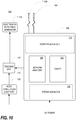
- FIG. 9 is a block diagram of the handheld control unit 250 of FIG. 8 .
- the block diagram shows the internal tracking unit 218 and its connections to the AC/DC Converters and Battery in the Power Block 260 and to the Tablet 162.
- FIG. 10 is a block diagram of an electromagnetic field bio-sensing and bio-imaging (EMFBioSI) system 410 .
- the system 410 is similar to that of FIG. 1 , but having two probes 164 .
- FIG. 11 is a perspective view of the handheld control unit 450 and two probes 164, 464 of the EMFBioSI system 410
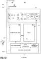
- FIG. 12 is a block diagram of the control unit 450 of FIG. 10
- the control unit 450 is similar to that of FIG. 3 , but having a second probe connection 468 to the second port of the VNA 156 for a second probe 464.
- the probe connection 468 utilizes a high quality coaxial cable 468.
- probe 1 164 and probe 2 464 both deliver and collect or receive EM signals after they pass through the interrogation region. After being received, they are processed by the Doppler sub-block 170, with the output being processed by an application on the tablet computer 162.
- each received signal is sometimes referred to hereinafter as S jk , where the index j refers to the jth port of the VNS that transmits the original electromagnetic signal from the VNA 156 via a cable and antenna in the probe 164 toward the interrogation zone, and the index k refers to the kth port of the VNA 156 that receives the reflected/scattered signal.
- S jk the index j refers to the jth port of the VNS that transmits the original electromagnetic signal from the VNA 156 via a cable and antenna in the probe 164 toward the interrogation zone
- the index k refers to the kth port of the VNA 156 that receives the reflected/scattered signal.
- probe 1 164 irradiates an EM signal which is scattered by the tissue and then received by probe 1 164.
- the signal received by probe 1 is referred to as S 11 .
- the EM signal irradiated by probe 1 164 may also be received by probe 2 464; if used, this signal is referred to as S 12 .
- probe 2 464 may also irradiate an EM signal which is scattered by the tissue and then received by probe 1 164, probe 2 464, or both.
- a signal irradiated by probe 2 464 and received by probe 1 164 may be referred to as S 21 ; a signal both irradiated and received by probe 2 464 may be referred to as S 22 .
- probe 1 164 receives the reflected and scattered signals S 11 and S 21 from the arm tissue and returns a signal to the Doppler Sub-block 170 where processing continues through just as it does in system 110 and then the digitized signals on the ADC outputs 212,214 are provided to the DSP 220 or directly to a computer 162 for further signal analysis and processing.
- S 12 is received by the VNA 156 and passed through a connection to the tablet 162 for further analysis and processing.
- FIG. 13 is a perspective view of the two probes 164,464 used in the EMFBioSI system 410, placed on an arm.
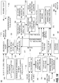
- FIG. 14 is a flow diagram of the operational process 500 of the EMFBioSI system 410 of FIG. 10 and is similar to the flow diagram of the operational process 300 with the differences detailed hereinbelow.
- ECG electrocardiography
- the process 500 also utilizes additional data and other information, obtained or derived prior to operation and stored in a database or elsewhere in the system 410.
- Such information which serves as control data, includes material type information (control data) 510 pertaining to the how the characteristics of S jk vary based on whether S jk pass through tissue, air, or a gel, and tissue status information (control data) 512 pertaining to "normal,” “suspicious,” and "abnormal" characteristics of S jk .
- material type information or control data 510 may be obtained via physical/biophysical experiments, while the tissue status information or control data 512 may be obtained during previous clinical procedures when a particular EM signal S jk is correlated with tissue pathological studies.
- the material type control data 510 is used in a decision block 516 where it is determined whether both probes 164, 464 are on biologic tissue 163 or not. In order to facilitate ease of use by the operator, an indication of whether the probes 164, 464 are properly on the tissue 163 or not. Such an indication might include a green light, a beep, or the like. A corresponding indication when the probes 164, 464 are not on the tissue, such as a red light, a buzzer, or the like, may also be provided.
- the material type control data 510 is also provided as an input to a filter 320. Once it is determined the probes are on tissue 163 and the signal is within a valid range to pass the filter 320, the signal is ready for complex S jk signal analysis at block 526.
- This block 526 also requires input from the tissue status control data 512 and a blood flow analyzer 350.
- the tissue status control data which corresponds to the differences in the value of S jk resulting from normal, suspicious, or abnormal tissue, is stored in a computer database and is compared on-line with the received EM signal S jk . Correlation and cross-correlation analysis as well as pattern recognition methods may be used.
- the operational process 500 of the EMFBioSI system 410 of FIG. 10 receives input from position tracking sensors 166 located in probe 1 164 and probe 2 464.
- the information from these sensors 166 is needed in order to provide two dimensional and three-dimensional tissue surface mapping or tissue imaging, as the signal location and angle should be known for proper image reconstruction.
- the operational process 300 culminates with visualization and imaging and matching analysis at block 370.
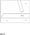
- FIG. 15 is a perspective view of a probe combination and FIG. 16 is a perspective view of the probe of FIG. 15 , being placed on a human arm.
- a stationary probe built into a stable base surface, such as a tabletop, serves as a second probe, thereby leaving the operator with a free hand while manipulating the first probe with his or her other hand.
- the position of the stationary probe relative to the stable base surface is thus defined.
- operation of this system is similar to the two probe implementation described previously.
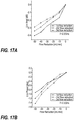
- FIG. 17A is a graph showing the changes in amplitude of Electromagnetic signals passed through a swine extremity due to a reduction in femoral blood flow.
- FIG. 17B is a graph showing the changes in phase of Electromagnetic signals passed through a swine extremity due to a reduction in femoral blood flow.
- FIG. 18A is a graph showing the changes in amplitude and phase of electromagnetic signals passed through a swine extremity due to elevated compartmental pressure.
- FIG. 18B is a graph showing the decrease in femoral blood flow due to elevated compartmental pressure in FIG. 18A . Excess of a fluid in the compartment, depending on the degree of extra-pressure, compromises arterial blood flow up to the point of a total occlusion, creating tissue ischemia/infarction. The frequency was 2.5GHz.
Landscapes
- Health & Medical Sciences (AREA)
- Life Sciences & Earth Sciences (AREA)
- Engineering & Computer Science (AREA)
- Physics & Mathematics (AREA)
- General Health & Medical Sciences (AREA)
- Public Health (AREA)
- Pathology (AREA)
- Veterinary Medicine (AREA)
- Biomedical Technology (AREA)
- Heart & Thoracic Surgery (AREA)
- Medical Informatics (AREA)
- Molecular Biology (AREA)
- Surgery (AREA)
- Animal Behavior & Ethology (AREA)
- Biophysics (AREA)
- Nuclear Medicine, Radiotherapy & Molecular Imaging (AREA)
- Radiology & Medical Imaging (AREA)
- Physiology (AREA)
- Hematology (AREA)
- Cardiology (AREA)
- Computer Vision & Pattern Recognition (AREA)
- Signal Processing (AREA)
- Psychiatry (AREA)
- Artificial Intelligence (AREA)
- Electromagnetism (AREA)
- High Energy & Nuclear Physics (AREA)
- Measuring Pulse, Heart Rate, Blood Pressure Or Blood Flow (AREA)
- Measurement And Recording Of Electrical Phenomena And Electrical Characteristics Of The Living Body (AREA)
Claims (18)
- Verfahren zum Bewerten des Zustands eines biologischen Gewebes (163), umfassend:Einstrahlen eines elektromagnetischen Signals (152) über eine Sonde (164) in ein biologisches Gewebe;Empfangen des eingestrahlten elektromagnetischen Signals, nachdem das Signal von dem biologischen Gewebe gestreut/reflektiert wurde;Bereitstellen von Blutflussvolumeninformationen über das biologische Gewebe mithilfe eines Blutflussanalysators (350), um das Blutvolumen zu bestimmen;Analysieren (326) des empfangenen Signals basierend zumindest auf den bereitgestellten Blutflussvolumeninformationen zusammen mit der Kenntnis elektromagnetischer Signaldifferenzen in normalem, verdächtigem und abnormalem Gewebe;Verwenden (330) eines Algorithmus zur Rekonstruktion dielektrischer Eigenschaften (332), der die dielektrischen Eigenschaften des biologischen Gewebes basierend zumindest auf den Ergebnissen des Analyseschritts zusammen mit den Blutflussvolumeninformationen rekonstruiert;Verwenden (336) eines Algorithmus zur Rekonstruktion der Gewebeeigenschaften (338), der die Gewebeeigenschaften des biologischen Gewebes basierend zumindest teilweise auf den Ergebnissen des Rekonstruktionsschrittes zusammen mit den Blutflussvolumeninformationen rekonstruiert; undAusgeben der Abbildung (370) der dielektrischen Eigenschaften des Gewebes.
- Verfahren nach Anspruch 1, ferner umfassend einen vorhergehenden Schritt des Bestimmens (316), ob sich die Sonde in der Nähe des biologischen Gewebes befindet, ferner umfassend einen Schritt des Bereitstellens über die Sonde eines Hinweises dazu, ob die Sonde als in der Nähe des biologischen Gewebes befindlich bestimmt wurde, und wobei der Schritt des Bestimmens, ob sich die Sonde in der Nähe des biologischen Gewebes befindet, mindestens teilweise auf der Kenntnis der elektromagnetischen Signaldifferenzen in biologischem Gewebe, Luft und einem Gel basiert.
- Verfahren nach Anspruch 1, wobei das Empfangen des eingestrahlten elektromagnetischen Signals das Empfangen des eingestrahlten elektromagnetischen Signals an einer Sonde umfasst.
- Verfahren nach Anspruch 3, ferner umfassend einen Schritt des Bestimmens der Position der Sonde, die das eingestrahlte elektromagnetische Signal empfängt, über eine Verfolgungseinheit, während der Empfangsschritt ausgeführt wird.
- Verfahren nach Anspruch 4, ferner umfassend einen Schritt des Korrelierens der bestimmten Position der Sonde mit bekannten Informationen über die Position und die Kontouren des biologischen Gewebes und ferner umfassend einen Oberflächenbehandlungsprozess, der vor dem Schritt des Empfangen des eingestrahlten elektromagnetischen Signals ausgeführt wird, wobei die Position der Sonde, in mindestens zwei Dimensionen, wiederholt bestimmt wird, wenn die Sonde an verschiedenen Stellen gegen die Oberfläche des biologischen Gewebes platziert wird, wodurch eine digitale Karte der Oberfläche des biologischen Gewebes entsteht, die anschließend in dem Korrelationsschritt verwendet wird.
- Verfahren nach Anspruch 1, wobei die Blutflussinformationen mindestens teilweise auf der Basis eines Schrittes des Synchronisierens des empfangenen elektromagnetischen Signals mit einem Signal bereitgestellt wird, das einen Blutkreislauf des biologischen Gewebes darstellt.
- Verfahren nach Anspruch 6, wobei die Blutflussinformationen nach dem Synchronisierschritt mindestens teilweise auf der Basis eines Schrittes des Verarbeitens des synchronisierten Signals mittels kohärenter Mittelung bereitgestellt werden.
- Verfahren nach Anspruch 6, wobei der Schritt des Bereitstellens der Blutflussinformationen das Bereitstellen von Blutvolumeninformationen umfasst.
- Verfahren nach Anspruch 1, wobei das eingestrahlte elektromagnetische Signal ein erstes elektromagnetisches Signal ist, wobei das empfangene elektromagnetische Signal ein zweites elektromagnetisches Signal ist und wobei das Verfahren ferner einen Schritt zum Verarbeiten des ersten und des zweiten elektromagnetischen Signals mittels einem Doppler-Teilblock umfasst.
- Verfahren nach Anspruch 9, wobei die Blutflussinformationen mindestens teilweise auf der Basis eines Schrittes des Synchronisierens einer Ausgabe des Doppler-Teilblocks mit einem Signal bereitgestellt werden, das einen Blutkreislauf des biologischen Gewebes darstellt.
- Verfahren nach Anspruch 1, wobei der Schritt des Analysierens des empfangenen Signals einen vorhergehenden Schritt des Erhaltens der Kenntnis der elektromagnetischen Signaldifferenzen in normalem, verdächtigem und abnormalem Gewebe während klinischer Verfahren umfasst.
- Verfahren nach Anspruch 1, wobei der Schritt des Rekonstruierens von Gewebeeigenschaften des biologischen Gewebes das Rekonstruieren von mindestens einem des zellulären Volumenanteils (VFcell), der intrazellulären Leitfähigkeit (σintracell) und der extrazellulären Leitfähigkeit (σextracell) umfasst.
- Verfahren nach Anspruch 1, ferner umfassend nach dem Schritt des Rekonstruierens von Gewebeeigenschaften des biologischen Gewebes einen Schritt des Durchführens von Visualisierung, Bildgebung und Matching-Analyse.
- Schritt nach Anspruch 13, wobei der Schritt des Durchführens der Visualisierung, Bildgebung und Matching-Analyse zumindest teilweise auf Ergebnissen des Schrittes des Rekonstruierens dielektrischer Eigenschaften des biologischen Gewebes basiert.
- Verfahren nach Anspruch 14, wobei dielektrische Eigenschaftsinformationen basierend auf der Frequenz eine Eingabe in den Schritt des Durchführens der Visualisierung, Bildgebung und Matching-Analyse sind, oder wobei dielektrische Eigenschaftsinformationen basierend auf der Zeit eine Eingabe in den Schritt des Durchführens der Visualisierung, Bildgebung und Matching-Analyse sind.
- Verfahren nach Anspruch 13, wobei der Schritt des Durchführens der Visualisierung, Bildgebung und Matching-Analyse zumindest teilweise auf Ergebnissen des Schrittes des Bereitstellens der Blutflussinformationen basiert.
- Verfahren zum Abbilden eines biologischen Gewebes (163) zum Identifizieren und Lokalisieren von Gewebeabnormalitäten, umfassend:Einstrahlen eines elektromagnetischen Signals (152) über eine Sonde (164) in die Nähe eines biologischen Gewebes, wobei die Sonde eine Sendesonde definiert;an einer Sonde Empfangen des eingestrahlten elektromagnetischen Signals (152), nachdem das Signal von dem biologischen Gewebe gestreut/reflektiert wurde, wobei die Sonde eine Empfangssonde definiert;Bereitstellen von Blutflussvolumeninformationen über das biologische Gewebe mithilfe eines Blutflussanalysators (350), um das Blutvolumen zu bestimmen;Verwenden (336) eines Algorithmus zum Rekonstruieren von Gewebeeigenschaften (338) und Blutflussvolumeninformationen, der die Gewebeeigenschaften des biologischen Gewebes rekonstruiert;Bestimmen (352) über eine Verfolgungseinheit (118) der Position von mindestens einer der Sendesonde und der Empfangssonde, während der Schritt des Empfangens ausgeführt wird, wobei die mindestens eine Sonde eine verfolgte Sonde definiert; undKorrelieren (370) der rekonstruierten Gewebeeigenschaften mit der bestimmten Sondenposition, sodass der Gewebezustand wie Abnormalitäten identifiziert und räumlich lokalisiert werden kann; undAusgeben eines Hinweises (380) auf den Gewebezustand.
- Auf einem elektromagnetischen Feld basierendes tragbares Biomessungs- und Biobildgebungssystem (100), das dazu ausgelegt ist, einen der Ansprüche 1 bis 17 zu implementieren, wobei das System umfasst: eine tragbare Steuereinheit (150), eine tragbare Sonde (164), einen externen Elektromagnetfeldgenerator (112), eine externe Verfolgungseinheit (118), einen Blutflussanalysator (350) und eine Bildgebungseinheit (370), die die Abbildung der dielektrischen Eigenschaften des Gewebes ausgibt.
Applications Claiming Priority (3)
| Application Number | Priority Date | Filing Date | Title |
|---|---|---|---|
| US201361802339P | 2013-03-15 | 2013-03-15 | |
| US13/894,401 US20140275944A1 (en) | 2013-03-15 | 2013-05-14 | Handheld electromagnetic field-based bio-sensing and bio-imaging system |
| PCT/US2014/023793 WO2014150616A2 (en) | 2013-03-15 | 2014-03-11 | Handheld electromagnetic field-based bio-sensing and bio-imaging system |
Publications (3)
| Publication Number | Publication Date |
|---|---|
| EP2967412A2 EP2967412A2 (de) | 2016-01-20 |
| EP2967412A4 EP2967412A4 (de) | 2016-10-19 |
| EP2967412B1 true EP2967412B1 (de) | 2020-06-17 |
Family
ID=51530390
Family Applications (1)
| Application Number | Title | Priority Date | Filing Date |
|---|---|---|---|
| EP14768372.6A Active EP2967412B1 (de) | 2013-03-15 | 2014-03-11 | Auf einem elektromagnetischen feld basierendes tragbares biomessungs- und biobildgebungssystem |
Country Status (5)
| Country | Link |
|---|---|
| US (7) | US20140275944A1 (de) |
| EP (1) | EP2967412B1 (de) |
| ES (1) | ES2808662T3 (de) |
| RU (1) | RU2665189C2 (de) |
| WO (1) | WO2014150616A2 (de) |
Cited By (2)
| Publication number | Priority date | Publication date | Assignee | Title |
|---|---|---|---|---|
| US11806121B2 (en) | 2013-03-15 | 2023-11-07 | Emtensor Gmbh | Methods of identifying and locating tissue abnormalities in a biological tissue |
| US12290347B2 (en) | 2016-11-23 | 2025-05-06 | Emtensor Gmbh | Use of electromagnetic field for tomographic imaging of head |
Families Citing this family (17)
| Publication number | Priority date | Publication date | Assignee | Title |
|---|---|---|---|---|
| US9724010B2 (en) | 2010-07-08 | 2017-08-08 | Emtensor Gmbh | Systems and methods of 4D electromagnetic tomographic (EMT) differential (dynamic) fused imaging |
| WO2014081992A2 (en) | 2012-11-21 | 2014-05-30 | Emtensor Gmbh | Electromagnetic tomography solutions for scanning head |
| US9072449B2 (en) | 2013-03-15 | 2015-07-07 | Emtensor Gmbh | Wearable/man-portable electromagnetic tomographic imaging |
| RU2711205C2 (ru) * | 2015-08-26 | 2020-01-15 | Кимберли-Кларк Ворлдвайд, Инк. | Портативные устройства для магнитоиндукционной томографии |
| WO2017066731A1 (en) | 2015-10-16 | 2017-04-20 | Emtensor Gmbh | Electromagnetic interference pattern recognition tomography |
| CN110177498B (zh) | 2016-12-06 | 2024-03-15 | 麦德菲尔德诊断有限公司 | 用于检测主体中的不对称定位的内部对象的系统和方法 |
| WO2018127434A1 (en) | 2017-01-09 | 2018-07-12 | Medfield Diagnostics Ab | Method and system for ensuring antenna contact and system function in applications of detecting internal dielectric properties in a body |
| US11723579B2 (en) | 2017-09-19 | 2023-08-15 | Neuroenhancement Lab, LLC | Method and apparatus for neuroenhancement |
| US11717686B2 (en) | 2017-12-04 | 2023-08-08 | Neuroenhancement Lab, LLC | Method and apparatus for neuroenhancement to facilitate learning and performance |
| US12280219B2 (en) | 2017-12-31 | 2025-04-22 | NeuroLight, Inc. | Method and apparatus for neuroenhancement to enhance emotional response |
| US11273283B2 (en) | 2017-12-31 | 2022-03-15 | Neuroenhancement Lab, LLC | Method and apparatus for neuroenhancement to enhance emotional response |
| US11364361B2 (en) | 2018-04-20 | 2022-06-21 | Neuroenhancement Lab, LLC | System and method for inducing sleep by transplanting mental states |
| WO2020056418A1 (en) | 2018-09-14 | 2020-03-19 | Neuroenhancement Lab, LLC | System and method of improving sleep |
| SG11202108602VA (en) * | 2019-02-18 | 2021-09-29 | Univ Iowa State Res Found Inc | Resonant sensors for wireless monitoring of cell concentration |
| SE2050674A1 (en) | 2020-06-09 | 2021-12-10 | Medfield Diagnostics Ab | Classification of radio frequency scattering data |
| US12048518B2 (en) * | 2020-09-22 | 2024-07-30 | Serguei Semenov | Individually wearable electromagnetic sensing (iwEMS) system and method for non-invasive assessment of tissue blood and oxygen content |
| US20240011925A1 (en) * | 2022-07-05 | 2024-01-11 | Southern Methodist University | Noninvasive water content sensor |
Family Cites Families (95)
| Publication number | Priority date | Publication date | Assignee | Title |
|---|---|---|---|---|
| US4157472A (en) | 1976-09-16 | 1979-06-05 | General Electric Company | X-ray body scanner for computerized tomography |
| US4135131A (en) | 1977-10-14 | 1979-01-16 | The United States Of America As Represented By The Secretary Of The Army | Microwave time delay spectroscopic methods and apparatus for remote interrogation of biological targets |
| US4247815A (en) | 1979-05-22 | 1981-01-27 | The United States Of America As Represented By The Secretary Of The Army | Method and apparatus for physiologic facsimile imaging of biologic targets based on complex permittivity measurements using remote microwave interrogation |
| US4257278A (en) * | 1979-08-24 | 1981-03-24 | General Electric Company | Quantitative volume blood flow measurement by an ultrasound imaging system featuring a Doppler modality |
| US4638813A (en) * | 1980-04-02 | 1987-01-27 | Bsd Medical Corporation | Electric field probe |
| US4662222A (en) | 1984-12-21 | 1987-05-05 | Johnson Steven A | Apparatus and method for acoustic imaging using inverse scattering techniques |
| US4662722A (en) | 1985-05-23 | 1987-05-05 | Ford Aerospace & Communications Corp. | Polarization insensitive mirror |
| DE3531893A1 (de) | 1985-09-06 | 1987-03-19 | Siemens Ag | Verfahren zur bestimmung der verteilung der dielektrizitaetskonstanten in einem untersuchungskoerper sowie messanordnung zur durchfuehrung des verfahrens |
| DE3601983A1 (de) | 1986-01-23 | 1987-07-30 | Siemens Ag | Verfahren und vorrichtung zur beruehrungslosen bestimmung der temperaturverteilung in einem untersuchungsobjekt |
| US4926868A (en) | 1987-04-15 | 1990-05-22 | Larsen Lawrence E | Method and apparatus for cardiac hemodynamic monitor |
| US5069223A (en) | 1990-02-14 | 1991-12-03 | Georgetown University | Method of evaluating tissue changes resulting from therapeutic hyperthermia |
| US5363050A (en) | 1990-08-31 | 1994-11-08 | Guo Wendy W | Quantitative dielectric imaging system |
| US5233713A (en) | 1991-03-27 | 1993-08-10 | General Electric Company | Head holder for nuclear imaging |
| US5222501A (en) | 1992-01-31 | 1993-06-29 | Duke University | Methods for the diagnosis and ablation treatment of ventricular tachycardia |
| US5305748A (en) | 1992-06-05 | 1994-04-26 | Wilk Peter J | Medical diagnostic system and related method |
| US5263050A (en) | 1992-09-09 | 1993-11-16 | Echelon Corporation | Adaptive threshold in a spread spectrum communications system |
| US5405346A (en) | 1993-05-14 | 1995-04-11 | Fidus Medical Technology Corporation | Tunable microwave ablation catheter |
| ZA948393B (en) * | 1993-11-01 | 1995-06-26 | Polartechnics Ltd | Method and apparatus for tissue type recognition |
| US5715819A (en) | 1994-05-26 | 1998-02-10 | The Carolinas Heart Institute | Microwave tomographic spectroscopy system and method |
| AUPM851694A0 (en) | 1994-09-30 | 1994-10-27 | Barsamian, Sergei T | New methods for diagnosis, detection of cell abnormalities and morphology of living systems |
| US6026173A (en) | 1997-07-05 | 2000-02-15 | Svenson; Robert H. | Electromagnetic imaging and therapeutic (EMIT) systems |
| JP2001527456A (ja) * | 1997-05-23 | 2001-12-25 | ザ・カロライナス・ハート・インスティテュート | 電磁式画像処理装置及び診断装置 |
| US6522910B1 (en) | 1997-09-11 | 2003-02-18 | Wisys Technology Foundation | Electrical property enhanced tomography (EPET) apparatus and method |
| US6697660B1 (en) | 1998-01-23 | 2004-02-24 | Ctf Systems, Inc. | Method for functional brain imaging from magnetoencephalographic data by estimation of source signal-to-noise ratio |
| US6703838B2 (en) | 1998-04-13 | 2004-03-09 | Schlumberger Technology Corporation | Method and apparatus for measuring characteristics of geological formations |
| US6333087B1 (en) | 1998-08-27 | 2001-12-25 | Chevron Chemical Company Llc | Oxygen scavenging packaging |
| US6233479B1 (en) * | 1998-09-15 | 2001-05-15 | The Regents Of The University Of California | Microwave hematoma detector |
| US6454711B1 (en) | 1999-04-23 | 2002-09-24 | The Regents Of The University Of California | Microwave hemorrhagic stroke detector |
| US7373197B2 (en) * | 2000-03-03 | 2008-05-13 | Intramedical Imaging, Llc | Methods and devices to expand applications of intraoperative radiation probes |
| US6511427B1 (en) * | 2000-03-10 | 2003-01-28 | Acuson Corporation | System and method for assessing body-tissue properties using a medical ultrasound transducer probe with a body-tissue parameter measurement mechanism |
| US6481887B1 (en) | 2000-04-12 | 2002-11-19 | Ge Medical Systems Global Technology Company, Llc | Emergency vehicle with medical image scanner and teleradiology system and method of operation |
| US6503203B1 (en) | 2001-01-16 | 2003-01-07 | Koninklijke Philips Electronics N.V. | Automated ultrasound system for performing imaging studies utilizing ultrasound contrast agents |
| US6965661B2 (en) | 2001-06-19 | 2005-11-15 | Hitachi, Ltd. | Radiological imaging apparatus and radiological imaging method |
| CA2451404C (en) * | 2001-07-06 | 2011-04-19 | Wisconsin Alumni Research Foundation | Space-time microwave imaging for cancer detection |
| CA2462341C (en) * | 2001-10-12 | 2010-12-14 | Wisconsin Alumni Research Foundation | Microwave dielectric spectroscopy method and apparatus for assays of proteins and other biological molecules |
| WO2003051197A1 (en) | 2001-12-18 | 2003-06-26 | Mri Devices Corporation | Method and apparatus for noise tomography |
| US7164105B2 (en) | 2002-04-05 | 2007-01-16 | Microwave Imaging Systems Technologies, Inc. | Non-invasive microwave analysis systems |
| US8892189B2 (en) * | 2002-05-30 | 2014-11-18 | Alcatel Lucent | Apparatus and method for heart size measurement using microwave doppler radar |
| EP1538972B1 (de) | 2002-08-01 | 2013-11-13 | California Institute Of Technology | Fernmessmethode und vorrichtung |
| WO2004052169A2 (en) | 2002-09-27 | 2004-06-24 | The Trustees Of Dartmouth College | Imaging by magnetic resonance adsorption, elastography and tomography |
| US7239731B1 (en) | 2002-11-26 | 2007-07-03 | Emimaging Ltd | System and method for non-destructive functional imaging and mapping of electrical excitation of biological tissues using electromagnetic field tomography and spectroscopy |
| AU2003300052A1 (en) * | 2002-12-31 | 2004-08-10 | John Herbert Cafarella | Multi-sensor breast tumor detection |
| WO2004073618A2 (en) * | 2003-02-14 | 2004-09-02 | University Of Florida | Breast cancer detection system |
| JP4263579B2 (ja) * | 2003-10-22 | 2009-05-13 | アロカ株式会社 | 超音波診断装置 |
| US20050135560A1 (en) | 2003-12-17 | 2005-06-23 | Ehud Dafni | Portable computed tomography scanner and methods thereof |
| WO2005115235A1 (en) * | 2004-05-26 | 2005-12-08 | Medical Device Innovations Limited | Tissue detection and ablation apparatus and apparatus and method for actuating a tuner |
| US7782998B2 (en) | 2004-12-21 | 2010-08-24 | General Electric Company | Method and apparatus for correcting motion in image reconstruction |
| US8253619B2 (en) | 2005-02-15 | 2012-08-28 | Techtronic Power Tools Technology Limited | Electromagnetic scanning imager |
| US7962198B2 (en) | 2005-04-27 | 2011-06-14 | The Trustees Of Dartmouth College | System and method for spectral-encoded high-rate hemodynamic tomography |
| DE102005026940A1 (de) | 2005-06-06 | 2006-12-14 | Schering Ag | Röntgenanordnung zur Bilddarstellung eines Untersuchungsobjektes und Verwendung der Röntgenanordnung |
| US20070025514A1 (en) | 2005-06-06 | 2007-02-01 | Ruediger Lawaczeck | X-ray arrangement for graphic display of an object under examination and use of the x-ray arrangement |
| US7387607B2 (en) | 2005-06-06 | 2008-06-17 | Intel Corporation | Wireless medical sensor system |
| ATE500778T1 (de) | 2005-12-22 | 2011-03-15 | Visen Medical Inc | Kombiniertes röntgen- und optisches tomographie- bildgebungssystem |
| US9084556B2 (en) * | 2006-01-19 | 2015-07-21 | Toshiba Medical Systems Corporation | Apparatus for indicating locus of an ultrasonic probe, ultrasonic diagnostic apparatus |
| US8724864B2 (en) | 2006-05-22 | 2014-05-13 | Medfield Diagnostics Ab | System and method relating to examination of an object |
| ES2496148T3 (es) | 2006-06-29 | 2014-09-18 | Medfields Diagnostics Ab | Solución para la vigilancia interna del organismo |
| US9709733B2 (en) * | 2006-09-28 | 2017-07-18 | The Florida International University Board Of Trustees | Hand-held optical probe based imaging system with 3D tracking facilities |
| US8423152B2 (en) | 2007-05-14 | 2013-04-16 | Bsd Medical Corporation | Apparatus and method for selectively heating a deposit in fatty tissue in a body |
| US8089417B2 (en) * | 2007-06-01 | 2012-01-03 | The Royal Institution For The Advancement Of Learning/Mcgill University | Microwave scanning system and miniaturized microwave antenna |
| US7876114B2 (en) * | 2007-08-08 | 2011-01-25 | Cascade Microtech, Inc. | Differential waveguide probe |
| ES2664239T3 (es) * | 2007-09-05 | 2018-04-18 | Sensible Medical Innovations Ltd. | Método y aparato para usar radiación electromagnética para supervisar un tejido de un usuario |
| GB0721694D0 (en) | 2007-11-05 | 2007-12-12 | Univ Bristol | Methods and apparatus for measuring the contents of a search volume |
| GB0721693D0 (en) | 2007-11-05 | 2007-12-12 | Univ Bristol | Antenna for investigating structure of human or animal |
| US9672471B2 (en) | 2007-12-18 | 2017-06-06 | Gearbox Llc | Systems, devices, and methods for detecting occlusions in a biological subject including spectral learning |
| US8708919B1 (en) | 2008-01-25 | 2014-04-29 | Raytheon Company | System and method for remotely sensing vital signs |
| EP2403401B1 (de) * | 2009-03-04 | 2017-05-10 | Sensible Medical Innovations Ltd. | System zur überwachung von geweben im körper |
| JP5605783B2 (ja) * | 2009-06-10 | 2014-10-15 | 国立大学法人静岡大学 | 診断装置 |
| PL2457195T3 (pl) | 2009-07-23 | 2018-03-30 | Medfield Diagnostics Ab | Klasyfikacja danych dotyczących rozpraszania mikrofalowego |
| WO2011141915A2 (en) * | 2010-05-13 | 2011-11-17 | Sensible Medical Innovations Ltd. | Method and system for using distributed electromagnetic (em) tissue(s) monitoring |
| KR20130136907A (ko) | 2010-06-01 | 2013-12-13 | 어뎁턴스, 엘엘씨 | 네트워크 연결된 착용가능한 의료용 센서를 위한 시스템 및 방법 |
| US9635349B2 (en) * | 2010-06-11 | 2017-04-25 | The Florida International University Board Of Trustees | Second generation hand held optical imager |
| US9724010B2 (en) | 2010-07-08 | 2017-08-08 | Emtensor Gmbh | Systems and methods of 4D electromagnetic tomographic (EMT) differential (dynamic) fused imaging |
| RU2596984C2 (ru) | 2010-07-08 | 2016-09-10 | ИМИмиджинг Лтд | Системы и способы четырехмерного электромагнитного томографического (эмт) дифференциального (динамического) смешанного построения изображений |
| WO2012047841A2 (en) | 2010-10-04 | 2012-04-12 | Nuovoprobe Ltd. | System and method for electromagnetic imaging and therapeutics using specialized nanoparticles |
| US9079011B2 (en) | 2011-01-03 | 2015-07-14 | Wisconsin Alumni Research Foundation | Microwave hyperthermia treatment system |
| US9649091B2 (en) * | 2011-01-07 | 2017-05-16 | General Electric Company | Wireless ultrasound imaging system and method for wireless communication in an ultrasound imaging system |
| US8376948B2 (en) | 2011-02-17 | 2013-02-19 | Vivant Medical, Inc. | Energy-delivery device including ultrasound transducer array and phased antenna array |
| US9448187B2 (en) * | 2011-07-01 | 2016-09-20 | University Of Manitoba | Imaging using probes |
| DE102011106405B4 (de) | 2011-07-02 | 2021-08-12 | Drägerwerk AG & Co. KGaA | Elektroimpedanztomographie-Gerät |
| WO2013093923A2 (en) | 2011-12-20 | 2013-06-27 | Sensible Medical Innovations Ltd. | Thoracic garment of positioning electromagnetic (em) transducers and methods of using such thoracic garment |
| US10743815B2 (en) | 2012-01-19 | 2020-08-18 | Cerebrotech Medical Systems, Inc. | Detection and analysis of spatially varying fluid levels using magnetic signals |
| CA2863449C (en) | 2012-01-19 | 2019-07-02 | Cerebrotech Medical Systems, Inc. | Diagnostic system for detection of fluid changes |
| DE102012205294B3 (de) | 2012-03-30 | 2013-06-27 | Siemens Aktiengesellschaft | Verfahren und Steuereinrichtung zur Ansteuerung eines Magnetresonanzsystems |
| US9445729B2 (en) | 2012-07-20 | 2016-09-20 | Resmed Sensor Technologies Limited | Range gated radio frequency physiology sensor |
| WO2014081992A2 (en) | 2012-11-21 | 2014-05-30 | Emtensor Gmbh | Electromagnetic tomography solutions for scanning head |
| US20140275944A1 (en) | 2013-03-15 | 2014-09-18 | Emtensor Gmbh | Handheld electromagnetic field-based bio-sensing and bio-imaging system |
| US9072449B2 (en) | 2013-03-15 | 2015-07-07 | Emtensor Gmbh | Wearable/man-portable electromagnetic tomographic imaging |
| US9420977B2 (en) | 2014-03-19 | 2016-08-23 | Tribogenics, Inc. | Portable head CT scanner |
| EP3188653B1 (de) | 2014-09-03 | 2021-06-23 | Cerebrotech Medical Systems, Inc. | Vorrichtung zum nachweis und analyse von räumlich variierenden flüssigkeitspegeln unter verwendung von magnetischen signalen |
| WO2017066731A1 (en) | 2015-10-16 | 2017-04-20 | Emtensor Gmbh | Electromagnetic interference pattern recognition tomography |
| CN110177498B (zh) | 2016-12-06 | 2024-03-15 | 麦德菲尔德诊断有限公司 | 用于检测主体中的不对称定位的内部对象的系统和方法 |
| WO2018127434A1 (en) | 2017-01-09 | 2018-07-12 | Medfield Diagnostics Ab | Method and system for ensuring antenna contact and system function in applications of detecting internal dielectric properties in a body |
| WO2018223178A1 (en) | 2017-06-08 | 2018-12-13 | The University Of Queensland | A tomographic imaging system and process |
| CA3082344A1 (en) | 2017-11-13 | 2019-05-16 | Cerebrotech Medical Systems, Inc. | Continuous autoregulation system |
| CN112154570A (zh) | 2018-05-23 | 2020-12-29 | 麦德菲尔德诊断有限公司 | 用于微波吸收的方案 |
-
2013
- 2013-05-14 US US13/894,401 patent/US20140275944A1/en not_active Abandoned
-
2014
- 2014-03-11 EP EP14768372.6A patent/EP2967412B1/de active Active
- 2014-03-11 RU RU2015144025A patent/RU2665189C2/ru active
- 2014-03-11 ES ES14768372T patent/ES2808662T3/es active Active
- 2014-03-11 WO PCT/US2014/023793 patent/WO2014150616A2/en not_active Ceased
-
2015
- 2015-06-30 US US14/788,042 patent/US10492700B2/en active Active
-
2018
- 2018-04-25 US US15/962,738 patent/US10980435B2/en active Active
-
2021
- 2021-04-19 US US17/233,848 patent/US11517214B2/en active Active
-
2022
- 2022-12-05 US US18/075,224 patent/US11806121B2/en active Active
-
2023
- 2023-11-06 US US18/387,299 patent/US20240065569A1/en not_active Abandoned
-
2025
- 2025-01-17 US US19/030,092 patent/US20250261868A1/en active Pending
Non-Patent Citations (1)
| Title |
|---|
| None * |
Cited By (2)
| Publication number | Priority date | Publication date | Assignee | Title |
|---|---|---|---|---|
| US11806121B2 (en) | 2013-03-15 | 2023-11-07 | Emtensor Gmbh | Methods of identifying and locating tissue abnormalities in a biological tissue |
| US12290347B2 (en) | 2016-11-23 | 2025-05-06 | Emtensor Gmbh | Use of electromagnetic field for tomographic imaging of head |
Also Published As
| Publication number | Publication date |
|---|---|
| US20180235486A1 (en) | 2018-08-23 |
| US20240065569A1 (en) | 2024-02-29 |
| EP2967412A2 (de) | 2016-01-20 |
| US20210236008A1 (en) | 2021-08-05 |
| RU2015144025A3 (de) | 2018-03-07 |
| RU2015144025A (ru) | 2017-04-28 |
| ES2808662T3 (es) | 2021-03-01 |
| US20140275944A1 (en) | 2014-09-18 |
| US10492700B2 (en) | 2019-12-03 |
| RU2665189C2 (ru) | 2018-08-28 |
| US11517214B2 (en) | 2022-12-06 |
| WO2014150616A3 (en) | 2014-12-31 |
| US10980435B2 (en) | 2021-04-20 |
| US20250261868A1 (en) | 2025-08-21 |
| US20150342472A1 (en) | 2015-12-03 |
| US20230116876A1 (en) | 2023-04-13 |
| EP2967412A4 (de) | 2016-10-19 |
| WO2014150616A2 (en) | 2014-09-25 |
| US11806121B2 (en) | 2023-11-07 |
Similar Documents
| Publication | Publication Date | Title |
|---|---|---|
| US11806121B2 (en) | Methods of identifying and locating tissue abnormalities in a biological tissue | |
| EP3181045B1 (de) | Verfahren und systeme zur überwachung von intrakorporalem gewebe | |
| US20080200802A1 (en) | Platform for detection of tissue content and/or structural changes with closed-loop control in mammalian organisms | |
| US20100324415A1 (en) | Platform for detection of tissue structure change | |
| US20100022900A1 (en) | Non-Invasive Method And Device For Measuring Cardiac Output | |
| CN103068302A (zh) | 使用分布式电磁(em)组织监测的方法及系统 | |
| JP7036712B2 (ja) | 患者の健康状態の診断用の血行動態パラメータ(hdp)監視システム | |
| Pedersen et al. | An investigation of the use of microwave radiation for pulmonary diagnostics | |
| Gaddam et al. | On the Non-invasive Sensing of Arterial Waveform and Hematocrit using Microwaves | |
| US20230277079A1 (en) | Methods and systems for monitoring intrabody tissues | |
| Hanna et al. | Body-Responsive Electromagnetic Sensing for Future Health-Care Diagnostics: Toward new frontiers of noninvasive biomarker monitoring [Bioelectromagnetics] | |
| Shah et al. | Penetration depth evaluation of split ring resonator sensor using in-vivo microwave reflectivity and ultrasound measurements | |
| Libove et al. | Wearable brain imager/BMI technology for structural, vascular and functional extraction | |
| RU2730988C1 (ru) | Способ измерения частоты сердечных сокращений и частоты дыхательных движений и радиолокационный измеритель частоты сердечных сокращений и частоты дыхательных движений | |
| Bouchaala et al. | Medical Applications | |
| Alruwaili | Cardiac stroke volume measurement using a non-invasive wearable electromagnetic resonator | |
| IL239240A (en) | Methods and systems for internal tissue monitoring |
Legal Events
| Date | Code | Title | Description |
|---|---|---|---|
| PUAI | Public reference made under article 153(3) epc to a published international application that has entered the european phase |
Free format text: ORIGINAL CODE: 0009012 |
|
| 17P | Request for examination filed |
Effective date: 20150930 |
|
| AK | Designated contracting states |
Kind code of ref document: A2 Designated state(s): AL AT BE BG CH CY CZ DE DK EE ES FI FR GB GR HR HU IE IS IT LI LT LU LV MC MK MT NL NO PL PT RO RS SE SI SK SM TR |
|
| AX | Request for extension of the european patent |
Extension state: BA ME |
|
| DAX | Request for extension of the european patent (deleted) | ||
| A4 | Supplementary search report drawn up and despatched |
Effective date: 20160916 |
|
| RIC1 | Information provided on ipc code assigned before grant |
Ipc: A61B 5/05 20060101AFI20160912BHEP |
|
| STAA | Information on the status of an ep patent application or granted ep patent |
Free format text: STATUS: EXAMINATION IS IN PROGRESS |
|
| 17Q | First examination report despatched |
Effective date: 20180212 |
|
| GRAP | Despatch of communication of intention to grant a patent |
Free format text: ORIGINAL CODE: EPIDOSNIGR1 |
|
| STAA | Information on the status of an ep patent application or granted ep patent |
Free format text: STATUS: GRANT OF PATENT IS INTENDED |
|
| INTG | Intention to grant announced |
Effective date: 20191220 |
|
| GRAS | Grant fee paid |
Free format text: ORIGINAL CODE: EPIDOSNIGR3 |
|
| GRAA | (expected) grant |
Free format text: ORIGINAL CODE: 0009210 |
|
| STAA | Information on the status of an ep patent application or granted ep patent |
Free format text: STATUS: THE PATENT HAS BEEN GRANTED |
|
| AK | Designated contracting states |
Kind code of ref document: B1 Designated state(s): AL AT BE BG CH CY CZ DE DK EE ES FI FR GB GR HR HU IE IS IT LI LT LU LV MC MK MT NL NO PL PT RO RS SE SI SK SM TR |
|
| RAP1 | Party data changed (applicant data changed or rights of an application transferred) |
Owner name: SEMENOV, SERGUEI Y. Owner name: EMTENSOR GMBH |
|
| REG | Reference to a national code |
Ref country code: GB Ref legal event code: FG4D |
|
| REG | Reference to a national code |
Ref country code: CH Ref legal event code: EP |
|
| REG | Reference to a national code |
Ref country code: IE Ref legal event code: FG4D |
|
| REG | Reference to a national code |
Ref country code: DE Ref legal event code: R096 Ref document number: 602014066720 Country of ref document: DE |
|
| REG | Reference to a national code |
Ref country code: AT Ref legal event code: REF Ref document number: 1280364 Country of ref document: AT Kind code of ref document: T Effective date: 20200715 |
|
| REG | Reference to a national code |
Ref country code: DE Ref legal event code: R082 Ref document number: 602014066720 Country of ref document: DE Representative=s name: NOVAGRAAF BREVETS, FR Ref country code: DE Ref legal event code: R081 Ref document number: 602014066720 Country of ref document: DE Owner name: EMTENSOR GMBH, AT Free format text: FORMER OWNERS: EMTENSOR GMBH, VIENNA, AT; SEMENOV, SERGUEI Y., VIENNA, AT |
|
| RAP2 | Party data changed (patent owner data changed or rights of a patent transferred) |
Owner name: EMTENSOR GMBH |
|
| REG | Reference to a national code |
Ref country code: CH Ref legal event code: PK Free format text: BERICHTIGUNGEN |
|
| RIN2 | Information on inventor provided after grant (corrected) |
Inventor name: SEMENOV, SERGUEI Y. |
|
| PG25 | Lapsed in a contracting state [announced via postgrant information from national office to epo] |
Ref country code: LT Free format text: LAPSE BECAUSE OF FAILURE TO SUBMIT A TRANSLATION OF THE DESCRIPTION OR TO PAY THE FEE WITHIN THE PRESCRIBED TIME-LIMIT Effective date: 20200617 Ref country code: GR Free format text: LAPSE BECAUSE OF FAILURE TO SUBMIT A TRANSLATION OF THE DESCRIPTION OR TO PAY THE FEE WITHIN THE PRESCRIBED TIME-LIMIT Effective date: 20200918 Ref country code: FI Free format text: LAPSE BECAUSE OF FAILURE TO SUBMIT A TRANSLATION OF THE DESCRIPTION OR TO PAY THE FEE WITHIN THE PRESCRIBED TIME-LIMIT Effective date: 20200617 Ref country code: SE Free format text: LAPSE BECAUSE OF FAILURE TO SUBMIT A TRANSLATION OF THE DESCRIPTION OR TO PAY THE FEE WITHIN THE PRESCRIBED TIME-LIMIT Effective date: 20200617 Ref country code: NO Free format text: LAPSE BECAUSE OF FAILURE TO SUBMIT A TRANSLATION OF THE DESCRIPTION OR TO PAY THE FEE WITHIN THE PRESCRIBED TIME-LIMIT Effective date: 20200917 |
|
| REG | Reference to a national code |
Ref country code: LT Ref legal event code: MG4D |
|
| REG | Reference to a national code |
Ref country code: AT Ref legal event code: PC Ref document number: 1280364 Country of ref document: AT Kind code of ref document: T Owner name: EMTENSOR GMBH, AT Effective date: 20200917 |
|
| REG | Reference to a national code |
Ref country code: NL Ref legal event code: MP Effective date: 20200617 |
|
| PG25 | Lapsed in a contracting state [announced via postgrant information from national office to epo] |
Ref country code: BG Free format text: LAPSE BECAUSE OF FAILURE TO SUBMIT A TRANSLATION OF THE DESCRIPTION OR TO PAY THE FEE WITHIN THE PRESCRIBED TIME-LIMIT Effective date: 20200917 Ref country code: LV Free format text: LAPSE BECAUSE OF FAILURE TO SUBMIT A TRANSLATION OF THE DESCRIPTION OR TO PAY THE FEE WITHIN THE PRESCRIBED TIME-LIMIT Effective date: 20200617 Ref country code: RS Free format text: LAPSE BECAUSE OF FAILURE TO SUBMIT A TRANSLATION OF THE DESCRIPTION OR TO PAY THE FEE WITHIN THE PRESCRIBED TIME-LIMIT Effective date: 20200617 Ref country code: HR Free format text: LAPSE BECAUSE OF FAILURE TO SUBMIT A TRANSLATION OF THE DESCRIPTION OR TO PAY THE FEE WITHIN THE PRESCRIBED TIME-LIMIT Effective date: 20200617 |
|
| PG25 | Lapsed in a contracting state [announced via postgrant information from national office to epo] |
Ref country code: AL Free format text: LAPSE BECAUSE OF FAILURE TO SUBMIT A TRANSLATION OF THE DESCRIPTION OR TO PAY THE FEE WITHIN THE PRESCRIBED TIME-LIMIT Effective date: 20200617 Ref country code: NL Free format text: LAPSE BECAUSE OF FAILURE TO SUBMIT A TRANSLATION OF THE DESCRIPTION OR TO PAY THE FEE WITHIN THE PRESCRIBED TIME-LIMIT Effective date: 20200617 |
|
| PG25 | Lapsed in a contracting state [announced via postgrant information from national office to epo] |
Ref country code: EE Free format text: LAPSE BECAUSE OF FAILURE TO SUBMIT A TRANSLATION OF THE DESCRIPTION OR TO PAY THE FEE WITHIN THE PRESCRIBED TIME-LIMIT Effective date: 20200617 Ref country code: SM Free format text: LAPSE BECAUSE OF FAILURE TO SUBMIT A TRANSLATION OF THE DESCRIPTION OR TO PAY THE FEE WITHIN THE PRESCRIBED TIME-LIMIT Effective date: 20200617 Ref country code: RO Free format text: LAPSE BECAUSE OF FAILURE TO SUBMIT A TRANSLATION OF THE DESCRIPTION OR TO PAY THE FEE WITHIN THE PRESCRIBED TIME-LIMIT Effective date: 20200617 Ref country code: CZ Free format text: LAPSE BECAUSE OF FAILURE TO SUBMIT A TRANSLATION OF THE DESCRIPTION OR TO PAY THE FEE WITHIN THE PRESCRIBED TIME-LIMIT Effective date: 20200617 Ref country code: PT Free format text: LAPSE BECAUSE OF FAILURE TO SUBMIT A TRANSLATION OF THE DESCRIPTION OR TO PAY THE FEE WITHIN THE PRESCRIBED TIME-LIMIT Effective date: 20201019 |
|
| PG25 | Lapsed in a contracting state [announced via postgrant information from national office to epo] |
Ref country code: SK Free format text: LAPSE BECAUSE OF FAILURE TO SUBMIT A TRANSLATION OF THE DESCRIPTION OR TO PAY THE FEE WITHIN THE PRESCRIBED TIME-LIMIT Effective date: 20200617 Ref country code: PL Free format text: LAPSE BECAUSE OF FAILURE TO SUBMIT A TRANSLATION OF THE DESCRIPTION OR TO PAY THE FEE WITHIN THE PRESCRIBED TIME-LIMIT Effective date: 20200617 Ref country code: IS Free format text: LAPSE BECAUSE OF FAILURE TO SUBMIT A TRANSLATION OF THE DESCRIPTION OR TO PAY THE FEE WITHIN THE PRESCRIBED TIME-LIMIT Effective date: 20201017 |
|
| REG | Reference to a national code |
Ref country code: ES Ref legal event code: FG2A Ref document number: 2808662 Country of ref document: ES Kind code of ref document: T3 Effective date: 20210301 |
|
| REG | Reference to a national code |
Ref country code: DE Ref legal event code: R097 Ref document number: 602014066720 Country of ref document: DE |
|
| PLBE | No opposition filed within time limit |
Free format text: ORIGINAL CODE: 0009261 |
|
| STAA | Information on the status of an ep patent application or granted ep patent |
Free format text: STATUS: NO OPPOSITION FILED WITHIN TIME LIMIT |
|
| PG25 | Lapsed in a contracting state [announced via postgrant information from national office to epo] |
Ref country code: DK Free format text: LAPSE BECAUSE OF FAILURE TO SUBMIT A TRANSLATION OF THE DESCRIPTION OR TO PAY THE FEE WITHIN THE PRESCRIBED TIME-LIMIT Effective date: 20200617 |
|
| 26N | No opposition filed |
Effective date: 20210318 |
|
| PG25 | Lapsed in a contracting state [announced via postgrant information from national office to epo] |
Ref country code: SI Free format text: LAPSE BECAUSE OF FAILURE TO SUBMIT A TRANSLATION OF THE DESCRIPTION OR TO PAY THE FEE WITHIN THE PRESCRIBED TIME-LIMIT Effective date: 20200617 |
|
| PG25 | Lapsed in a contracting state [announced via postgrant information from national office to epo] |
Ref country code: MC Free format text: LAPSE BECAUSE OF FAILURE TO SUBMIT A TRANSLATION OF THE DESCRIPTION OR TO PAY THE FEE WITHIN THE PRESCRIBED TIME-LIMIT Effective date: 20200617 |
|
| REG | Reference to a national code |
Ref country code: CH Ref legal event code: PL |
|
| REG | Reference to a national code |
Ref country code: BE Ref legal event code: MM Effective date: 20210331 |
|
| PG25 | Lapsed in a contracting state [announced via postgrant information from national office to epo] |
Ref country code: IE Free format text: LAPSE BECAUSE OF NON-PAYMENT OF DUE FEES Effective date: 20210311 Ref country code: LI Free format text: LAPSE BECAUSE OF NON-PAYMENT OF DUE FEES Effective date: 20210331 Ref country code: LU Free format text: LAPSE BECAUSE OF NON-PAYMENT OF DUE FEES Effective date: 20210311 Ref country code: CH Free format text: LAPSE BECAUSE OF NON-PAYMENT OF DUE FEES Effective date: 20210331 |
|
| REG | Reference to a national code |
Ref country code: AT Ref legal event code: UEP Ref document number: 1280364 Country of ref document: AT Kind code of ref document: T Effective date: 20200617 |
|
| PG25 | Lapsed in a contracting state [announced via postgrant information from national office to epo] |
Ref country code: BE Free format text: LAPSE BECAUSE OF NON-PAYMENT OF DUE FEES Effective date: 20210331 |
|
| REG | Reference to a national code |
Ref country code: FR Ref legal event code: PLFP Year of fee payment: 10 |
|
| PG25 | Lapsed in a contracting state [announced via postgrant information from national office to epo] |
Ref country code: HU Free format text: LAPSE BECAUSE OF FAILURE TO SUBMIT A TRANSLATION OF THE DESCRIPTION OR TO PAY THE FEE WITHIN THE PRESCRIBED TIME-LIMIT; INVALID AB INITIO Effective date: 20140311 |
|
| PG25 | Lapsed in a contracting state [announced via postgrant information from national office to epo] |
Ref country code: CY Free format text: LAPSE BECAUSE OF FAILURE TO SUBMIT A TRANSLATION OF THE DESCRIPTION OR TO PAY THE FEE WITHIN THE PRESCRIBED TIME-LIMIT Effective date: 20200617 |
|
| PG25 | Lapsed in a contracting state [announced via postgrant information from national office to epo] |
Ref country code: MK Free format text: LAPSE BECAUSE OF FAILURE TO SUBMIT A TRANSLATION OF THE DESCRIPTION OR TO PAY THE FEE WITHIN THE PRESCRIBED TIME-LIMIT Effective date: 20200617 |
|
| PG25 | Lapsed in a contracting state [announced via postgrant information from national office to epo] |
Ref country code: MT Free format text: LAPSE BECAUSE OF FAILURE TO SUBMIT A TRANSLATION OF THE DESCRIPTION OR TO PAY THE FEE WITHIN THE PRESCRIBED TIME-LIMIT Effective date: 20200617 |
|
| PGFP | Annual fee paid to national office [announced via postgrant information from national office to epo] |
Ref country code: DE Payment date: 20250327 Year of fee payment: 12 |
|
| PGFP | Annual fee paid to national office [announced via postgrant information from national office to epo] |
Ref country code: AT Payment date: 20250318 Year of fee payment: 12 |
|
| PGFP | Annual fee paid to national office [announced via postgrant information from national office to epo] |
Ref country code: FR Payment date: 20250324 Year of fee payment: 12 |
|
| PGFP | Annual fee paid to national office [announced via postgrant information from national office to epo] |
Ref country code: IT Payment date: 20250321 Year of fee payment: 12 Ref country code: GB Payment date: 20250204 Year of fee payment: 12 |
|
| PGFP | Annual fee paid to national office [announced via postgrant information from national office to epo] |
Ref country code: ES Payment date: 20250417 Year of fee payment: 12 |
|
| PG25 | Lapsed in a contracting state [announced via postgrant information from national office to epo] |
Ref country code: TR Free format text: LAPSE BECAUSE OF FAILURE TO SUBMIT A TRANSLATION OF THE DESCRIPTION OR TO PAY THE FEE WITHIN THE PRESCRIBED TIME-LIMIT Effective date: 20200617 |