EP2965930B1 - Appareil de commande pour une installation a air comprime d'un vehicule utilitaire - Google Patents
Appareil de commande pour une installation a air comprime d'un vehicule utilitaire Download PDFInfo
- Publication number
- EP2965930B1 EP2965930B1 EP15175995.8A EP15175995A EP2965930B1 EP 2965930 B1 EP2965930 B1 EP 2965930B1 EP 15175995 A EP15175995 A EP 15175995A EP 2965930 B1 EP2965930 B1 EP 2965930B1
- Authority
- EP
- European Patent Office
- Prior art keywords
- air suspension
- suspension system
- cabin
- control
- control device
- Prior art date
- Legal status (The legal status is an assumption and is not a legal conclusion. Google has not performed a legal analysis and makes no representation as to the accuracy of the status listed.)
- Active
Links
- 239000000725 suspension Substances 0.000 claims description 240
- 230000008859 change Effects 0.000 claims description 51
- 238000013016 damping Methods 0.000 claims description 22
- 230000033001 locomotion Effects 0.000 claims description 22
- 238000000034 method Methods 0.000 claims description 20
- 230000001133 acceleration Effects 0.000 claims description 13
- 230000000694 effects Effects 0.000 claims description 9
- 238000005096 rolling process Methods 0.000 claims description 7
- 238000012545 processing Methods 0.000 claims description 6
- 230000003068 static effect Effects 0.000 claims description 6
- 230000008569 process Effects 0.000 claims description 3
- 238000012546 transfer Methods 0.000 claims description 3
- 230000033228 biological regulation Effects 0.000 description 56
- 238000009423 ventilation Methods 0.000 description 25
- 238000011068 loading method Methods 0.000 description 14
- 230000001105 regulatory effect Effects 0.000 description 13
- 230000001276 controlling effect Effects 0.000 description 9
- 230000010355 oscillation Effects 0.000 description 6
- 230000009471 action Effects 0.000 description 4
- 230000000903 blocking effect Effects 0.000 description 4
- 238000006073 displacement reaction Methods 0.000 description 4
- 238000012549 training Methods 0.000 description 4
- 230000001052 transient effect Effects 0.000 description 4
- 238000013459 approach Methods 0.000 description 3
- 230000005540 biological transmission Effects 0.000 description 3
- 230000015572 biosynthetic process Effects 0.000 description 3
- 230000009849 deactivation Effects 0.000 description 3
- 230000007423 decrease Effects 0.000 description 3
- 230000001419 dependent effect Effects 0.000 description 3
- 238000013461 design Methods 0.000 description 3
- 230000010354 integration Effects 0.000 description 3
- 238000005259 measurement Methods 0.000 description 3
- 230000009467 reduction Effects 0.000 description 3
- 210000002023 somite Anatomy 0.000 description 3
- 241000282414 Homo sapiens Species 0.000 description 2
- 230000008901 benefit Effects 0.000 description 2
- 238000002485 combustion reaction Methods 0.000 description 2
- 238000004891 communication Methods 0.000 description 2
- 230000008878 coupling Effects 0.000 description 2
- 238000010168 coupling process Methods 0.000 description 2
- 238000005859 coupling reaction Methods 0.000 description 2
- 238000001514 detection method Methods 0.000 description 2
- 238000011161 development Methods 0.000 description 2
- 230000018109 developmental process Effects 0.000 description 2
- 238000011156 evaluation Methods 0.000 description 2
- 238000011049 filling Methods 0.000 description 2
- 230000006870 function Effects 0.000 description 2
- 230000004044 response Effects 0.000 description 2
- 239000006096 absorbing agent Substances 0.000 description 1
- 230000006978 adaptation Effects 0.000 description 1
- 238000007605 air drying Methods 0.000 description 1
- 230000003466 anti-cipated effect Effects 0.000 description 1
- 238000004364 calculation method Methods 0.000 description 1
- 238000010276 construction Methods 0.000 description 1
- 238000000151 deposition Methods 0.000 description 1
- 238000001035 drying Methods 0.000 description 1
- 230000005284 excitation Effects 0.000 description 1
- 230000006872 improvement Effects 0.000 description 1
- 230000000977 initiatory effect Effects 0.000 description 1
- 239000012212 insulator Substances 0.000 description 1
- 230000003993 interaction Effects 0.000 description 1
- 230000007774 longterm Effects 0.000 description 1
- 230000008929 regeneration Effects 0.000 description 1
- 238000011069 regeneration method Methods 0.000 description 1
- 244000037459 secondary consumers Species 0.000 description 1
- 230000035939 shock Effects 0.000 description 1
- 230000006641 stabilisation Effects 0.000 description 1
- 238000011105 stabilization Methods 0.000 description 1
- 239000003381 stabilizer Substances 0.000 description 1
- 238000013022 venting Methods 0.000 description 1
Images


Classifications
-
- B—PERFORMING OPERATIONS; TRANSPORTING
- B60—VEHICLES IN GENERAL
- B60G—VEHICLE SUSPENSION ARRANGEMENTS
- B60G99/00—Subject matter not provided for in other groups of this subclass
- B60G99/002—Suspension details of the suspension of the vehicle body on the vehicle chassis
-
- B—PERFORMING OPERATIONS; TRANSPORTING
- B60—VEHICLES IN GENERAL
- B60G—VEHICLE SUSPENSION ARRANGEMENTS
- B60G17/00—Resilient suspensions having means for adjusting the spring or vibration-damper characteristics, for regulating the distance between a supporting surface and a sprung part of vehicle or for locking suspension during use to meet varying vehicular or surface conditions, e.g. due to speed or load
- B60G17/015—Resilient suspensions having means for adjusting the spring or vibration-damper characteristics, for regulating the distance between a supporting surface and a sprung part of vehicle or for locking suspension during use to meet varying vehicular or surface conditions, e.g. due to speed or load the regulating means comprising electric or electronic elements
- B60G17/016—Resilient suspensions having means for adjusting the spring or vibration-damper characteristics, for regulating the distance between a supporting surface and a sprung part of vehicle or for locking suspension during use to meet varying vehicular or surface conditions, e.g. due to speed or load the regulating means comprising electric or electronic elements characterised by their responsiveness, when the vehicle is travelling, to specific motion, a specific condition, or driver input
-
- B—PERFORMING OPERATIONS; TRANSPORTING
- B60—VEHICLES IN GENERAL
- B60G—VEHICLE SUSPENSION ARRANGEMENTS
- B60G17/00—Resilient suspensions having means for adjusting the spring or vibration-damper characteristics, for regulating the distance between a supporting surface and a sprung part of vehicle or for locking suspension during use to meet varying vehicular or surface conditions, e.g. due to speed or load
- B60G17/015—Resilient suspensions having means for adjusting the spring or vibration-damper characteristics, for regulating the distance between a supporting surface and a sprung part of vehicle or for locking suspension during use to meet varying vehicular or surface conditions, e.g. due to speed or load the regulating means comprising electric or electronic elements
- B60G17/017—Resilient suspensions having means for adjusting the spring or vibration-damper characteristics, for regulating the distance between a supporting surface and a sprung part of vehicle or for locking suspension during use to meet varying vehicular or surface conditions, e.g. due to speed or load the regulating means comprising electric or electronic elements characterised by their use when the vehicle is stationary, e.g. during loading, engine start-up or switch-off
-
- B—PERFORMING OPERATIONS; TRANSPORTING
- B60—VEHICLES IN GENERAL
- B60G—VEHICLE SUSPENSION ARRANGEMENTS
- B60G17/00—Resilient suspensions having means for adjusting the spring or vibration-damper characteristics, for regulating the distance between a supporting surface and a sprung part of vehicle or for locking suspension during use to meet varying vehicular or surface conditions, e.g. due to speed or load
- B60G17/015—Resilient suspensions having means for adjusting the spring or vibration-damper characteristics, for regulating the distance between a supporting surface and a sprung part of vehicle or for locking suspension during use to meet varying vehicular or surface conditions, e.g. due to speed or load the regulating means comprising electric or electronic elements
- B60G17/018—Resilient suspensions having means for adjusting the spring or vibration-damper characteristics, for regulating the distance between a supporting surface and a sprung part of vehicle or for locking suspension during use to meet varying vehicular or surface conditions, e.g. due to speed or load the regulating means comprising electric or electronic elements characterised by the use of a specific signal treatment or control method
-
- B—PERFORMING OPERATIONS; TRANSPORTING
- B60—VEHICLES IN GENERAL
- B60G—VEHICLE SUSPENSION ARRANGEMENTS
- B60G17/00—Resilient suspensions having means for adjusting the spring or vibration-damper characteristics, for regulating the distance between a supporting surface and a sprung part of vehicle or for locking suspension during use to meet varying vehicular or surface conditions, e.g. due to speed or load
- B60G17/02—Spring characteristics, e.g. mechanical springs and mechanical adjusting means
- B60G17/04—Spring characteristics, e.g. mechanical springs and mechanical adjusting means fluid spring characteristics
- B60G17/052—Pneumatic spring characteristics
-
- B—PERFORMING OPERATIONS; TRANSPORTING
- B60—VEHICLES IN GENERAL
- B60G—VEHICLE SUSPENSION ARRANGEMENTS
- B60G17/00—Resilient suspensions having means for adjusting the spring or vibration-damper characteristics, for regulating the distance between a supporting surface and a sprung part of vehicle or for locking suspension during use to meet varying vehicular or surface conditions, e.g. due to speed or load
- B60G17/06—Characteristics of dampers, e.g. mechanical dampers
- B60G17/08—Characteristics of fluid dampers
-
- B—PERFORMING OPERATIONS; TRANSPORTING
- B60—VEHICLES IN GENERAL
- B60G—VEHICLE SUSPENSION ARRANGEMENTS
- B60G2202/00—Indexing codes relating to the type of spring, damper or actuator
- B60G2202/10—Type of spring
- B60G2202/15—Fluid spring
- B60G2202/152—Pneumatic spring
-
- B—PERFORMING OPERATIONS; TRANSPORTING
- B60—VEHICLES IN GENERAL
- B60G—VEHICLE SUSPENSION ARRANGEMENTS
- B60G2202/00—Indexing codes relating to the type of spring, damper or actuator
- B60G2202/20—Type of damper
- B60G2202/24—Fluid damper
-
- B—PERFORMING OPERATIONS; TRANSPORTING
- B60—VEHICLES IN GENERAL
- B60G—VEHICLE SUSPENSION ARRANGEMENTS
- B60G2204/00—Indexing codes related to suspensions per se or to auxiliary parts
- B60G2204/10—Mounting of suspension elements
- B60G2204/16—Mounting of vehicle body on chassis
- B60G2204/162—Cabins, e.g. for trucks, tractors
-
- B—PERFORMING OPERATIONS; TRANSPORTING
- B60—VEHICLES IN GENERAL
- B60G—VEHICLE SUSPENSION ARRANGEMENTS
- B60G2400/00—Indexing codes relating to detected, measured or calculated conditions or factors
- B60G2400/05—Attitude
- B60G2400/053—Angular acceleration
- B60G2400/0531—Roll acceleration
-
- B—PERFORMING OPERATIONS; TRANSPORTING
- B60—VEHICLES IN GENERAL
- B60G—VEHICLE SUSPENSION ARRANGEMENTS
- B60G2400/00—Indexing codes relating to detected, measured or calculated conditions or factors
- B60G2400/05—Attitude
- B60G2400/053—Angular acceleration
- B60G2400/0532—Pitch acceleration
-
- B—PERFORMING OPERATIONS; TRANSPORTING
- B60—VEHICLES IN GENERAL
- B60G—VEHICLE SUSPENSION ARRANGEMENTS
- B60G2400/00—Indexing codes relating to detected, measured or calculated conditions or factors
- B60G2400/05—Attitude
- B60G2400/053—Angular acceleration
- B60G2400/0533—Yaw acceleration
-
- B—PERFORMING OPERATIONS; TRANSPORTING
- B60—VEHICLES IN GENERAL
- B60G—VEHICLE SUSPENSION ARRANGEMENTS
- B60G2400/00—Indexing codes relating to detected, measured or calculated conditions or factors
- B60G2400/20—Speed
- B60G2400/204—Vehicle speed
-
- B—PERFORMING OPERATIONS; TRANSPORTING
- B60—VEHICLES IN GENERAL
- B60G—VEHICLE SUSPENSION ARRANGEMENTS
- B60G2400/00—Indexing codes relating to detected, measured or calculated conditions or factors
- B60G2400/25—Stroke; Height; Displacement
- B60G2400/252—Stroke; Height; Displacement vertical
-
- B—PERFORMING OPERATIONS; TRANSPORTING
- B60—VEHICLES IN GENERAL
- B60G—VEHICLE SUSPENSION ARRANGEMENTS
- B60G2400/00—Indexing codes relating to detected, measured or calculated conditions or factors
- B60G2400/30—Propulsion unit conditions
- B60G2400/39—Brake pedal position
-
- B—PERFORMING OPERATIONS; TRANSPORTING
- B60—VEHICLES IN GENERAL
- B60G—VEHICLE SUSPENSION ARRANGEMENTS
- B60G2400/00—Indexing codes relating to detected, measured or calculated conditions or factors
- B60G2400/40—Steering conditions
- B60G2400/41—Steering angle
-
- B—PERFORMING OPERATIONS; TRANSPORTING
- B60—VEHICLES IN GENERAL
- B60G—VEHICLE SUSPENSION ARRANGEMENTS
- B60G2400/00—Indexing codes relating to detected, measured or calculated conditions or factors
- B60G2400/50—Pressure
- B60G2400/51—Pressure in suspension unit
- B60G2400/512—Pressure in suspension unit in spring
- B60G2400/5122—Fluid spring
- B60G2400/51222—Pneumatic
-
- B—PERFORMING OPERATIONS; TRANSPORTING
- B60—VEHICLES IN GENERAL
- B60G—VEHICLE SUSPENSION ARRANGEMENTS
- B60G2400/00—Indexing codes relating to detected, measured or calculated conditions or factors
- B60G2400/50—Pressure
- B60G2400/52—Pressure in tyre
-
- B—PERFORMING OPERATIONS; TRANSPORTING
- B60—VEHICLES IN GENERAL
- B60G—VEHICLE SUSPENSION ARRANGEMENTS
- B60G2400/00—Indexing codes relating to detected, measured or calculated conditions or factors
- B60G2400/90—Other conditions or factors
-
- B—PERFORMING OPERATIONS; TRANSPORTING
- B60—VEHICLES IN GENERAL
- B60G—VEHICLE SUSPENSION ARRANGEMENTS
- B60G2500/00—Indexing codes relating to the regulated action or device
- B60G2500/10—Damping action or damper
-
- B—PERFORMING OPERATIONS; TRANSPORTING
- B60—VEHICLES IN GENERAL
- B60G—VEHICLE SUSPENSION ARRANGEMENTS
- B60G2500/00—Indexing codes relating to the regulated action or device
- B60G2500/20—Spring action or springs
-
- B—PERFORMING OPERATIONS; TRANSPORTING
- B60—VEHICLES IN GENERAL
- B60G—VEHICLE SUSPENSION ARRANGEMENTS
- B60G2800/00—Indexing codes relating to the type of movement or to the condition of the vehicle and to the end result to be achieved by the control action
- B60G2800/70—Estimating or calculating vehicle parameters or state variables
Definitions
- the invention relates to a control device for a compressed air system of a commercial vehicle, a compressed air system of a commercial vehicle with such a control device and a method for operating a compressed air system of a commercial vehicle.
- Modern commercial vehicles on the one hand have a chassis air suspension system and on the other hand via a cabin air suspension system, which may be pneumatically interconnected or pneumatically decoupled in a compressed air system.
- the chassis air suspension system is used to control or regulate a constant or varying level of the chassis relative to the roadway, which is quasi-stationary, for example for loading and unloading, and / or dynamically while the commercial vehicle is driving when accelerating, braking and cornering to avoid unwanted Rolling, pitching or yawing the chassis may be the case.
- the control or regulation of the chassis air suspension system via the change in the application of air spring bellows, which are arranged between an axis of the utility vehicle and / or wheels of the utility vehicle and the chassis, and / or adjustment of dampers, which between wheels and chassis or axle and Chassis act.
- control of a chassis air suspension system is required to adapt the level to a loading and unloading ramp, which may be automatic or by manual control by the driver.
- the cabin air suspension system By means of the cabin air suspension system, the cabin of the commercial vehicle is supported with air bellows and dampers against the chassis.
- the control or regulation of the cabin air suspension system takes place, for example, with the aim of lowering the car for getting in and out, to make the level of the car independent of the loading and the weight of the people arranged in the cabin and dynamic movements of the cabin, in particular a pitching motion, a rolling motion and a yawing motion of the car, at least to reduce.
- EP 0 520 148 B1 discloses a chassis air suspension system in which a compressed air source configured as a reservoir is pneumatically connected to airfoil bellows supporting the chassis via a level control valve assembly and a lift / lower valve assembly.
- the level control valve assembly is automatically controlled by mechanical actuation according to a change in the level of the chassis to a vent position, a locked position, or a vent position.
- the level control valve assembly is used to specify and maintain a desired level height during driving.
- the lift / lower valve assembly allows the dormant vehicle operator to arbitrarily change the level, ie, raise or lower the chassis, for example, to accommodate a ramp for loading and unloading operations.
- the lifting-lowering valve assembly has a selector lever, which can be pivoted about a rotation axis with a switching shaft between pivoting positions lifting, lowering and stop.
- the switching shaft carries cams, via which, depending on the rotation angle of the switching shaft and the selector lever ram can be actuated, which in turn actuate inlet and outlet valves.
- an inlet valve is opened which connects a port of the lift / lower valve assembly connected to the compressed air source bypassing the level control valve assembly to an exit to the air bellows.
- an outlet valve is opened, which vents the outlet leading to the air bellows.
- the lifting-lowering valve assembly In the stop position between the lift and lower positions, the aforementioned intake and exhaust valves are closed, so that the pressure at the air suspension bellows is kept constant.
- a so-called dead man's spring is used, which is designed as a torsion spring.
- the dead man's pen leads the Selector lever with selector shaft from a manually raised or lowered position back to the Stop position when the driver stops applying power to the selector lever.
- the lifting-lowering valve assembly also has a pneumatic control port, which opens into a pressure chamber.
- the pressure chamber is limited by a control piston which is formed by an end face of the switching shaft.
- an axial displacement of the switching shaft with selector lever can be brought about, which has the consequence that a connecting valve is opened when the inlet valve is closed and the outlet valve is closed.
- the level control valve assembly is connected to the air bellows via the lift / lower valve assembly so that the level in the air bellows can be automatically controlled by the level control valve assembly.
- the induced by pneumatic pressurization of the pressure chamber position corresponds to a position ride, which is automatically taken over a control unit with appropriate control of a solenoid valve and thus controlled control pressure when the vehicle is in motion and, for example, a speed limit is exceeded.
- This air suspension system is based on a pneumatic series connection of the lift / lower valve assembly, the level control valve assembly and the air suspension bellows (with the said bypass options).
- a purely mechanical level control with manual intervention options via the lifting-lowering valve assembly is based on a pneumatic series connection of the lift / lower valve assembly, the level control valve assembly and the air suspension bellows (with the said bypass options).
- EP 1 382 469 A2 are between a compressed air source and the chassis supporting air spring bellows a 2/2-way valve in training as a check valve and a 3/2-way valve in training as a ventilation valve interposed.
- the two valves mentioned can be actuated both directly via associated electromagnets by a control unit for electrical level control as well as manually operated directly via a valve associated with the plunger to manually cause a lifting or lowering.
- DE 199 44 873 C1 discloses a chassis air suspension system in which a mechanically controlled level control valve assembly is arranged in parallel leg in a first line branch and in a second line branch, a purely electrically controlled level control valve assembly is arranged.
- the mechanical Level control valve assembly in the first leg has a level sensor whose output signal is fed to a control unit which, based also on this level signal, controls the purely electrically controlled level control valve assembly in the other leg.
- the control unit also controls a in the first line branch controlled shut-off valve, via which this first line branch can be shut off when the purely electronic level control is carried out in the second leg.
- a compressed air source via a mechanical level control valve assembly, a lifting-lowering valve assembly, a shuttle valve and a purely electrically controlled level control valve assembly is connected in series with bellows.
- the driver can manually influence the level of the chassis air suspension system both via the lift / lower valve assembly and via an electrical selector switch, which can also be used to manually raise and lower with proper voltage supply via the purely electronic level control valve assembly.
- the publication DE 199 16 040 B4 discloses a chassis air suspension system in which between the compressed air source and the here two-circuit, the chassis supporting air spring bellows a level control valve assembly is interposed.
- the level control valves of the level control valve assembly are electrically and pneumatically controllable via a manually operated lifting-lowering valve assembly.
- the control units of the level control valves generate according to the DIN symbol used for this purpose, a control pressure for a control piston of the level control valve using an electrically controlled electro-pneumatic pilot valve from a pressure which is supplied to the control unit of the lifting-lowering valve assembly.
- EP 1 687 159 B1 discloses the parallel arrangement of a solely by a control unit electrically operated line branch with a level control valve assembly with a vent valve in the form of a 3/2-way solenoid valve and a check valve in the form of a 2/2-way solenoid valve and a line branch with a lifting-lowering Valve assembly with two manually operable valves, namely a vent valve in training as a 3/2-way valve and a check valve in training as a 2/2-way valve.
- valves of the level control valve assembly are controlled purely pneumatically, wherein the control pressure is set by a series circuit of a controlled by the control unit 3/2-solenoid valve and a purely manually controlled 3/2-way valve, so that both an electrical and manual influencing one and the same control pressure is possible.
- Compressed air passes from a reservoir via the manually operated 3/2-way valves exclusively via the electrically operated 3/2-way solenoid valves to the respective control connection of the level control valves.
- EP 1 687 160 B1 discloses (in addition to embodiments accordingly EP 1 687 159 B1 ) An embodiment in which a reservoir is connected in pneumatic series connection via a check valve and a ventilation valve with air bellows. Both the check valve and the ventilation valve are alternatively controlled manually via actuating tappet and purely electrically actuated by a control unit electrically actuated solenoid actuators.
- EP 2 070 741 B1 discloses a lifting-lowering valve assembly, which is in addition to the manual operation and electro-pneumatically controlled by a passage position in a blocking position can be transferred. While the level control is activated for the moving vehicle and lifting / lowering valve assembly in the passage position and thus a raising, keeping constant and lowering the level depending on the level control valve is transferred to a ventilation position, blocking position and ventilation position, by automated switching of the lifting-lowering Valve assembly in the locked position the automatic level control disabled.
- This deactivation of the level control is used selectively according to an acceleration of the trailer. For example, the level control may be deactivated when there is a pitching of the vehicle in a braking operation or deflections due to a lateral acceleration when cornering. If no deactivation of the level control by the control unit would occur, caused by the respective acceleration and rebound operations of the bellows would lead to unnecessary level control actions with increased compressed air consumption.
- DE 10 2011 051 503 A1 discloses a chassis air suspension system in which the air suspension bellows supporting the chassis can be vented, shut off and vented by level control valves, the level control valves being pneumatically pilot operated are.
- the pneumatic pilot control takes place here via two alternative Vor Kunststoffpfade, namely a electronically controlled or regulated by a control unit Vor Kunststoffpfad in which the control unit controls or controls vor Kunststoffnde solenoid valves, and a manual Vor Kunststoffpfad, via which the driver by means of manually operated pilot valves lifting and lowering the chassis can bring about.
- WO 2014/046601 A1 discloses the integration of a chassis air suspension system, which may also include a lift axle here, into a compressed air conditioner which permits drying of compressed air supplied by a compressor, pressure control, distribution of compressed air to various consumer circuits, allowing regeneration of the air drying cartridge, control a filling order of the consumer circuits, the pressure relief over multi-circuit protection valves and the provision of a cross-feed between individual consumer circuits is used.
- WO 2014/046601 A1 discloses a chassis air suspension system.
- DE 10 2009 046 290 B3 describes a cabin air spring module interposed between a chassis and a cab of a commercial vehicle.
- the cabin air spring module forms an air spring bellows.
- a valve device is integrated, which causes depending on the rebound and rebound of the air spring bellows based on a mechanical path control a ventilation of the air spring bellows to ensure a constant level of the bellows and thus the cabin above the chassis.
- Out US 6,000,703A is a chassis air suspension system of a work vehicle such as a tractor known.
- an air suspension for a within the Cab be arranged arranged seat.
- each bellows a combination of a hydraulic actuator and an isolator for damping high-frequency vibrations is connected in parallel.
- the air bags carry a static proportion of the weight of the cabin, while on the combination of the actuator and the insulator a dynamic proportion of the weight of the cab should be supported.
- an electrically controlled solenoid valve is provided for each air spring bellows. The control is carried out by means of a control unit, taking into account the detected, acting on the bellows static load and possibly a detected at the bellows pressure.
- the actuation of the actuator is also controlled by a controlled electrically by the control unit solenoid valve, wherein the control in dependence Uneven ground, a deflection of the cab, a tilt and / or acceleration can be done.
- a cabin air suspension system in which also takes place a control of the air suspension of a seat in response to the control of the air suspension between the cabin and chassis.
- a control unit for controlling the ventilation of the bellows, a control unit is provided which controls in response to signals from position sensors and acceleration signals solenoid valves to forward additional volume from additional volume tanks in the air spring bellows.
- EP 1 584 545 B1 deals with the support of a cab of a commercial vehicle, which includes a rest room for rest or overnight breaks of the driver.
- the cabin In a parking situation of the commercial vehicle, the cabin should be oriented approximately horizontally, independently of any inclination of the roadway, in order to allow the driver to rest or sleep. Variations of the cabin, in particular due to the movement of the driver in the cabin, due to the wind and / or due to the wind of passing vehicles, should be avoided.
- an electronically controlled chassis air suspension system so-called " Electronically Controlled Air Suspension ", short ECAS
- ECAS Electronically Controlled Air Suspension
- the admission of air spring bellows of the cabin air suspension system is controlled by a further control unit and controlled by this solenoid valves.
- a mechanical stabilizer and shock absorbers with adjustable damping characteristics especially so-called CDC damper, use.
- CDC damper By means of the control unit of the cabin-air suspension system also a vibration control of the cabin should be made in order to avoid pitching oscillations in the acceleration and deceleration of the commercial vehicle, rolling or rolling movements u.
- the horizontal alignment of the car is accomplished, on the one hand, by the chassis of the ECAS system being oriented horizontally about the transverse axis by controlling the loading of a rear suspension and / or front suspension while shifting horizontally a vehicle longitudinal axis by means of an adjustment of the air spring bellows of the cabin air suspension system under control by the control unit of the cabin air suspension system takes place.
- the chassis air suspension system or ECAS system control unit and the cabin air suspension system control unit communicate with each other via a CAN bus. It is also proposed to reduce the chassis air suspension system by fully venting the air spring bellows on an axle stop to improve roll stabilization. Furthermore, it is proposed to maximize the damping of a damper in the parking situation in order to minimize movements of the cabin.
- the cabin air suspension system can evaluate the signal of an acceleration signal and based on the evaluation change the damping of the cabin air suspension system damper. Also possible is the consideration of a yaw rate sensor and / or a tilt sensor. For a simplified control, a control of the air spring bellows of the cabin air suspension system based on the signals of a speed sensor and / or a steering angle sensor is made taking into account a map.
- DE 103 60 875 B4 relates to the integration of air suspension electronics in an electronic braking system.
- the control programs of the air suspension system on the one hand and the electronic brake system on the other hand be equipped with a logic structure that are decoupled from each other so that the two control programs (for example, a software update) can be changed for themselves, bringing the air suspension system on the one hand and the electronic brake system On the other hand, the software should be largely self-sufficient.
- This patent does not deal with a cabin air suspension system.
- DE 10 2005 012 673 A1 relates to a commercial vehicle in which a vehicle frame via a chassis air suspension system is supported against the vehicle axles, while a cab is supported via a cabin air suspension system relative to the vehicle frame.
- a control or regulation of the two air suspension systems should be made, for example, for the purpose of aligning the cab horizontally at a standstill of the commercial vehicle on a sloped surface for a rest or overnight break or to avoid swaying the driver's cabin in gusts or wind influences passing vehicles.
- By means of separate displacement sensors and / or inclination sensors level and / or inclination changes on the one hand of the vehicle frame and on the other hand the driver's cab are detected.
- the independent control or regulation of the cabin air suspension system on the one hand and the chassis air suspension system on the other hand with the goal for the two air suspension systems each bring about a desired level and / or a desired inclination.
- a common control of both Luftfederbälgen (and damping elements) between the cab and vehicle frame and Heilfederbälgen (and damping elements) between the vehicle frame and vehicle axles done by means of a central control device, depending on the desired embodiment, all these elements or even parts thereof are controlled variably ,
- the non-generic document DE 10 2007 050 170 A1 relates to a motor vehicle in which over conventional suspension springs a structure is supported against vehicle wheels or axles. On the structure, again supported by conventional cab springs, a driver's cab.
- the suspension springs and the driver's cab springs each have suspension damping elements and driver's cab damping elements connected in parallel, the effective damping of which can be changed by common control electronics.
- the control electronics are the vehicle level descriptive level variables, additional level data of the brake system as a brake pedal actuation signal, the braking torque or a brake pressure, the drive torque of the vehicle engine, the vehicle longitudinal speed, wheel speeds of the vehicle wheels, a switching state of the clutch or the vehicle transmission and / or a steering angle supplied as measurement data.
- State variables such as a pitch variable describing the pitch movement, a roll size describing the roll motion, a stroke size describing the lift movement, and a transverse dynamics variable describing the lateral dynamics, such as the lateral acceleration, can be read by a state observer or the yaw rate and / or the vehicle longitudinal acceleration are estimated. On this basis, then carried by the control electronics, a vote of the suspension damping elements and the cab suspension elements. In this case, manipulated variables for the driver's cab damping elements can be determined from vehicle data for the chassis damping elements.
- the present invention has for its object to propose a control unit for a compressed air system of a commercial vehicle, a compressed air system and a method for operating a compressed air system, which or which more advanced intervention options for the control or regulation of the static and / or dynamic level of the chassis and / or the cabin of the commercial vehicle has.
- the invention proposes a control unit which is equipped both with control logic for controlling or regulating a chassis air suspension system for supporting a chassis of the commercial vehicle and with control logic for controlling or regulating a cabin air suspension system for supporting a driver's cab of the utility vehicle ,
- the said control logics can be part of a single software. It is also possible that the said control logics are parallelized on the control unit or executed on sub-processors of the control unit. It is possible that through the use of a multifunctional controller components such as a power supply, communication driver, Sensorauswertescharien u. ⁇ . Used both for the control or regulation of the chassis air suspension system as well as the control or regulation of the cabin air suspension system.
- control logics are decoupled from each other so that the two control logics can be changed for themselves, which is advantageous for any software update.
- the two control logics can be made largely self-sufficient by software.
- the chassis air suspension system and the cabin air suspension system are coordinated with each other so that the control or regulatory measures of the chassis air suspension system on the one hand and the cabin air suspension system on the other hand are not determined independently, but rather mutually dependent or to influence each other. It is possible that by the two control logics in the control unit, the chassis sub-vibration system and the cabin sub-vibration system are considered together as a total vibration system with the two intervention possibilities by the control logic at the Chassis air suspension system and the cabin air suspension system, then in the overall vibration system and the previously discussed interactions between the partial vibration systems can be considered. This will be explained with reference to the following, simplistic and non-limiting example:
- the controls or regulations exclusively control or regulate the ventilation of the involved air suspension bellows of the chassis air suspension system and the cabin air suspension system.
- the control unit is additionally equipped with control logic via which at least one damper of the chassis (or the cab) is controlled or regulated.
- the control or regulation of the at least one damper of the chassis (and / or the cabin) is coordinated with the controls or regulations of the chassis air suspension system and the cabin air suspension system.
- example can call, in the event that the control or regulation of the chassis air suspension system and / or the cabin air suspension system requires a large rate of change of a level, at the same time a damping of a parallel to the respective air spring bellows damper can be reduced, so that the loading or Ventilation of the air spring bellows must not take place against the force of a damper, whereby the speed of the control or regulation would be reduced.
- control unit is equipped with control logic, via which a control or regulation of a support arranged in the cabin seat takes place.
- control or regulation of a spring in particular an air spring bellows, and / or a damper, with which the seat is supported relative to the cabin, with respect to the height of the seat, the spring stiffness and / or the damping take place.
- the control of the seat support is coordinated with the controls or controls of the chassis air suspension system and the cabin air suspension system. In this way u. U. despite the control or regulation of the chassis air suspension system and the cabin air suspension system remaining vibration of the cabin are at least partially kept away from the driver.
- the control or regulation of the chassis air suspension system and / or cabin air suspension system takes place under direct control or regulation of ventilation and under pilot control of ventilation and exhaust valves by means of the control unit via electrical control signals controlled solenoid valves, which at any point in the Can be arranged commercial vehicle. It is possible that such solenoid valves may be combined in an electropneumatic cab control unit or an electropneumatic chassis control unit. In this case, the said control units can also form modules, which can also be combined with other control units to form a complete unit.
- control unit together with an electropneumatic cabin control unit and / or an electropneumatic chassis control unit, a structural unit, wherein it is also possible that sensors used in this unit for the control or regulation are integrated, via which for example a controlled or regulated pressure is monitored.
- control unit has at least one controlling or regulating output for a cabin air suspension system and / or a chassis air suspension system.
- control logic of the controller can then be carried out by the processing of at least one of these input signals, the control or chassis Luftfederungsstrom, the cabin Vietnamesefederungsstrom, a Heilfederbalges for the seat and / or a damper of the chassis, the cabin and / or the seat.
- control device is equipped with control logic, by means of which an automatic change of a static or average level height of the chassis takes place.
- the (average) level height of the chassis can be adjusted via the control unit.
- the automatic change consists of a change in the level height in the region of a ramp.
- the automatic change of the level height of the chassis may also be made to prepare the coupling with a trailer via a fifth wheel or to prepare for receiving a container.
- Another aspect of the invention is dedicated to a parking situation.
- This can for example be automatically detected by reaching a predetermined location, which is stored for example in a navigation system, in particular a rest and parking or a depot.
- a parking situation is detected with permanent speed of zero, actuation of the parking brake, deactivation of the internal combustion engine o. ⁇ .
- the driver informs the controller via a switch that a parking situation exists. In such a parking situation, a horizontal orientation of the car is desirable. This is done according to the invention by coordinated operation of the controls or regulations of the chassis air suspension system on the one hand and the cabin air suspension system on the other.
- the control or regulation for a direction in space by the chassis air suspension system and for another spatial direction by the cabin air suspension system takes place.
- the horizontal orientation of the car is brought about by the coordinated control or regulation of both the chassis air suspension system and the cabin air suspension system, so that a desired increase or decrease of the car from the sum of the increase or decrease of the Chassis and the raising or lowering of the car relative to the chassis results in u.
- the commercial vehicle with the chassis and the cabin forms a complex vibration system, which, as explained above, is at least a vibration system with two degrees of freedom, as explained above.
- the individual resiliently supported components of the commercial vehicle have a variety of degrees of freedom in all spatial directions. In order to take account of the mutual influences for the control or regulation in the control unit and u.
- the control logic of the controller a mechanical replacement model of the masses, springs and dampers to take into account the mechanical characteristics, in particular the tires, the tire support on the chassis and / or the support an axle on the chassis, the support of the driver's cab relative to the chassis and / or the support of the seat relative to the driver's cab is taken into account.
- the mechanical replacement model should be as simple as possible, but as complex as required to map the desired effects can be selected.
- the control logic of the controller a be taken into account from such a mechanical replacement model resulting transmission behavior.
- the controller for both the control and / or regulation of an electropneumatic chassis control unit and an electropneumatic Cabin control unit in charge.
- Another solution of the problem underlying the invention relates to a method for operating a compressed air system of a commercial vehicle.
- a single control unit controls or regulates both the chassis air suspension system and the cabin-Luftfederungsstrom, wherein the controls or regulations of the chassis air suspension system and the cabin air suspension system are coordinated by control logic of the controller such that the control or regulatory measures the chassis air suspension system on the one hand and the cabin air suspension system on the other hand are not determined independently, but they are mutually interdependent or mutually influence each other.
- the controls or regulations of the chassis air suspension system and the cabin air suspension system are coordinated with each other by using the control logic an effect of controlling or regulating the chassis air suspension system on the future movement behavior of the cabin without control or regulation of the cabin air suspension system is forecasted.
- a transient oscillation of the car may result as predicted future movement behavior.
- the control or regulation of the cabin-air suspension system then takes place in such a way that instead of the predicted movement behavior of the car, a desired movement behavior is brought about (or at least approximated).
- the control or regulation of the cabin-air suspension system can be carried out in such a way that the ventilation of the air suspension bellows of the cabin air suspension system just counteracts the formation of said transient oscillation.
- the chassis air suspension system is controlled or regulated in opposite directions to the cabin air suspension system. If ventilation is thus carried out, for example, in the case of the chassis air suspension system, the air suspension bellows of the cabin air suspension system are vented to the same extent or to a predetermined extent over a characteristic curve (and vice versa).
- the controls or arrangements of the chassis air suspension system and the cabin air suspension system are coordinated by the control logic in an automatically detected parking situation or manually indexed by the driver parking situation a horizontal orientation of the cabin both by changing the loading of the chassis Air suspension system and the cabin air suspension system is brought about.
- a damper of the chassis air suspension system on the control logic in a parking situation, a vibration of the cabin, especially when the driver in the cabin, wind or wind of a passing vehicle and / or the cabin air suspension system.
- the controls or regulations of the chassis air suspension system and the cabin air suspension system take into account a pressure in a container via which the chassis air suspension system and / or the cabin air suspension system are supplied with compressed air.
- This embodiment is based on the finding that a rate of change in the pressurization of the chassis air suspension system and / or the cabin air suspension system changes with a change in pressure in a container - for a large pressure in the container results in a large rate of change, while this a reduction in pressure decreases.
- This influencing variable can be taken into account by the embodiment according to the invention.
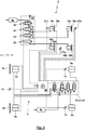
- electrical signal lines are dashed lines, modules or units dot-dashed lines and pneumatic lines shown by solid lines.
- Fig. 1 schematically shows a compressed air system 1 of a commercial vehicle, which has a chassis air suspension system 2 and a cabin air suspension system 3.
- the chassis air suspension system 2 and the cabin air suspension system are pneumatically coupled to each other by these are supplied from the same pressure medium source, here the same container 4, with compressed air.
- a level of the air spring bellows 5a, 5b and / or a level change speed in the area of the air spring bellows 5a, 5b or the dampers 6a, 6b can be detected via sensors 7a, 7b.
- a sensor 7c collectively detects a level in the region of the rear axle for the air spring bellows 5c, 5d and the dampers 6c, 6d. Accordingly, the pressure in an air spring bellows 5 a, 5 b can be detected via a pressure sensor 8 a, 8 b, while the pressure in the air spring bellows 5 c of the rear axle can be detected via a pressure sensor 8 c.
- the solenoid valve 9 is formed here as a 3/2-way valve which connects a non-electrically actuated position, a central line 12 with a vent 13, while with electrical loading of the solenoid valve 9 in the other switching position, the central line 12 via a supply line 14 to the container 4 is connectable.
- the central line 12 is vented and vented.
- the central line 12 branches via a branch to a central line part 12-1 and a central line part 12-2.
- the central pipe part 12-1 is connected to the air spring bellows 5b via the solenoid valve 10, while the central pipe part 12-2 is connected to the air spring bellows 5a via the solenoid valve 11.
- the solenoid valves 10, 11 are each formed as 2/2-way valves. In the in Fig. 1 effective, spring-loaded switching position without electrical control of the solenoid valves 10, 11 block these the associated air spring bellows 5a, 5b. If, however, a solenoid valve 10, 11 switched by electrical control in the passage position, the associated air spring bellows 5 a, 5 b depending on the switching position of the solenoid valve 9 be vented or vented. If both air spring bellows 5a, 5b are to be aerated or vented together, the two solenoid valves 9, 10 can be transferred simultaneously into their passage position.
- the solenoid valve 11 is transferred to its open position, the solenoid valve 10 is transferred to its blocking position and then the solenoid valve 9 is transferred to the ventilation position, whereby the air bag 5a is vented , Meanwhile, the solenoid valve 10 remains in its locked position.
- the solenoid valve 11 is transferred to its blocking position with subsequent transfer of the solenoid valve 10 in the passage position. Now the solenoid valve 9 can be transferred to the vent position, whereby the air bag 5b is vented.
- a rear axle 15 From the central line part 12-2 branches off a rear axle 15. This is connected to an input of a solenoid valve 16, which is designed here as a 3/2-way valve.
- the two outputs of the solenoid valve 16 are each connected to an air spring bellows 5c, 5d.
- the solenoid valve 16 locks in the in Fig. 1 effective switching position without electrical control of the input from the outputs, so that no connection of the rear axle 15 with the bellows 5c, 5d consists. Instead, in this switching position via the solenoid valve 16, the two air spring bellows 5c, 5d are pneumatically coupled to each other via a throttle 17 integrated in the solenoid valve 16.
- the solenoid valve 16 connects the input to the two outputs, so that the Schuachs effet 15 is connected to the air bags 5c, 5d.
- this switching position of the solenoid valve 16 depending on the switching position of the solenoid valve 9, a ventilation of the air spring bellows 5c, 5d done. If at least one of the solenoid valves 10, 11 is open, this can be done together with at least one of the bellows 5a, 5b, while on the other hand when transferring the solenoid valves 10, 11 in the locked position, the sole ventilation of the bellows 5c, 5d can be done.
- the cabin is supported via air spring bellows 18a, 18b, 18c, 18d and dampers 19a, 19b, 19c, 19d with respect to the chassis.
- the dampers 19 are integrated with the formation of an air spring-damper module 20 in the air spring bellows 18.
- the bellows 18b, 18d are directly pneumatically interconnected so that they have substantially equal pressures.
- the air suspension bellows 18a, 18c are each associated with sensors 21a, 21c, by means of which a relative level of the car relative to the chassis or a level change speed can be detected.
- a joint detection of an (averaged) relative level or a level change speed takes place via a sensor 21b.
- the solenoid valve 25 is designed as a 3/2-way valve.
- the solenoid valve 25 connects in the in Fig. 1 effective switching position without electrical loading a central line 26 with a vent 27, while the solenoid valve 25, in the other, can be brought by electrical control switch position, the central line 26 via a supply line 28 to the container 4.
- the central line 26 branches into central line parts 26-1, 26-2 and 26-3, which are each connected to a solenoid valve 22, 23, 24.
- central line parts 26-1, 26-2 and 26-3 which are each connected to a solenoid valve 22, 23, 24.
- control unit 30 In the compressed air system 1, the control or regulation of both the chassis air suspension system 2 and the cabin air suspension system 3 by a single, central control unit 30.
- the control unit 30 are for this purpose measurement signals, in particular measurement signals of the sensors 21 and the pressure sensors 29 of the cabin air suspension system 3 and the sensors 7 and pressure sensors 8 of the chassis air suspension system 2, supplied on the basis of which a control or regulation can take place.
- Control signals generated by control unit 30 (which are also understood to mean control signals) are controlled or regulation of the solenoid valves 9, 10, 11 and 16 of the chassis air suspension system 2 and the solenoid valves 22, 23, 24, 25 of the cabin air suspension system 3. It is possible that the control unit 30, for example via a bus system 31, with another control unit 32, for example, an ABS or EBS control unit, is networked and is in signal exchange.
- solenoid valves 22, 23, 24, 25 are summarized, here together with the pressure sensors 29a, 29b, 29c, to a cabin control unit 33.
- the solenoid valves 9, 10, 11 are combined to form a chassis control unit 34, here a front axle control unit 35.
- the solenoid valve 16 is part of a further chassis control unit 36, which here is a rear axle control unit 37.
- the cabin control unit 33 and the control unit 30 form a structural unit 38, with which a control unit 39 is formed, which can also assume electropneumatic functions.
- control unit 30 and the cabin control unit 33 are not combined to form a unit 38, but formed separately from each other, so that the control of the cabin control unit 33 is carried out by the control unit 30 via a control line 40.
- control unit 30 different from Fig. 1 no integration of the pressure sensors 29 in the cabin control unit 33 takes place - but these are outside the cabin control unit 33, for example, immediately adjacent to the air spring bellows 18, respectively.
- Fig. 2 finds another pressure sensor 41 use whose pressure signal is supplied to the control unit 30. About the pressure sensor 41, the pressure in the container 4, here the pressure in the supply line 28, detected.
- the pressure signal of the pressure sensor 41 can be determined in the control unit 30, which rate of change in a ventilation of an air spring bellows 18, 5 results in transfer of the associated solenoid valves in the ventilation position.
- the air spring bellows 18 and damper 19 are not combined to air spring damper modules 20, but formed separately from each other.
- Fig. 3 shows a compressed air system 1, in which the chassis air suspension system 2 and the cabin air suspension system 3 are pneumatically decoupled from each other by these two separate containers 4a, 4b are supplied with compressed air. Quite possible, however, that the two containers 4a, 4b in in Fig. 3 not shown in common, in particular by a compressed air treatment device with a multi-circuit protection valve for the compressed air supply to multiple consumer circuits to be supplied with compressed air.
- the cabin air suspension system 3 is basically according to the cabin air suspension system 3 according to Fig. 2 formed, but here the pressure sensors 29 are omitted.
- the front axle control unit 35 and the rear axle control unit 37 are combined with the same contained pneumatic components and wiring to a chassis control unit 42, in which in this case, the control unit 30 is integrated. Again, the pressure sensors 8 are omitted. Furthermore, no dampers 6a, 6b are associated with the air suspension bellows 5a, 5b of the front axle.
- units are formed in the figures, they may be formed with a one-piece or multi-part housing. Quite possible but also that these units are modular.
- the control unit 30 form a module
- the chassis control unit 42 forms another module, u. U. with sub-modules, which are formed by the front axle control unit 35 and the rear axle control unit 37.
- the modules are then coupled together, flanged to each other o. ⁇ .
- a cabin control unit 33 if necessary according to Fig. 1 together with the control unit 30, can be arranged in the region of the cabin or below it, so that it is not necessary that lines must be led into the cabin.
- the compressed air system according to the invention can be used and further developed suitable for a vehicle of any type and any axis design.
- the compressed air system as shown use for a two-axle vehicle, although quite a lift axle, a leading axle, a trailing axle o. ⁇ . May be present.
- U a preferred change of the admission of the air spring bellows done if a long-term change is to be brought about.
- UU can be prevented by means of an adjustment of the damping of a hydraulic damper, a rapid change in level.
- control units 33, 34, 35, 36, 37, 42 form pure electropneumatic units, in which case the sensors can integrated or can be arranged externally.
- a different pressure level for the air suspension systems 2, 3 find use.
- the cabin air suspension system 3 with the associated container 4a as a secondary consumer circuit or circuit with a reduced pressure, for example 8-10 bar be formed while the cabin air suspension system 3 with the associated container 4b as a high pressure circuit, for example with an operating pressure of 12 , 5 bar, can be trained.
- the control unit 30 is equipped with control logic, which is a control of both the chassis air suspension system 2 (with the control or regulation of the pressurization of the bellows 5 and / or the damper 6) and a control of the cabin air suspension system 3 (with a control of Pressurization of the bellows 18 and the damper 19) allows in a coordinated manner.
- a standard level during parking and a u Different default levels during driving, in some cases depending on speed, may be caused automatically or as a result of manual request.
- a dynamic control of the suspension and damping can be done. This can be done while driving the adjustment of a dynamic ride height. It is also possible that while driving, u. U. also speed-dependent, specifically an inclination of the driver's cab is changed, which can be done for example to influence the CW value by, for example, the driver's cab is tilted with recording the driving or exceeding a threshold speed.
- the damping can be influenced by at least one sensor, which may be a displacement sensor for the chassis, a displacement sensor for the cabin, a pressure sensor for the air spring bellows, an acceleration sensor or a steering angle sensor. Also possible is a dynamic, fast control while driving, to avoid oscillations of the chassis and / or cabin during accelerations, shifts, braking or steering operations. Automatically, a control can take place in a level height for a driving operation when it is detected that a gear is engaged, a minimum speed is exceeded, an internal combustion engine is started and / or a release of a parking brake takes place. It is entirely possible that signals from an EBS control unit, an ASR control unit, an ESP control unit are included in the control algorithm by the control unit 30, wherein these signals can be transmitted, for example, via a CAN or LIN.
- a level 43 of the cabin is shown as a function of time 44 while driving through a depression.
- the solid line 45 indicates an ideal level change of the level of the car for which the car would not change its absolute height despite entering into the subsidence. It can be seen that the level must rise to compensate for the lowering of the roadway in the area of the depression.
- the dashed line 46 the change in the level of the chassis is shown, which can be brought about with simultaneous ventilation of all bellows 5. Due to the throttle effects in the solenoid valves and the lines, the rate of change of the level is finite. In Fig. 4 It can be seen that line 46 can not follow line 45 due to these throttling effects.
- the ventilation of the air spring bellows 18 is thereby dimensioned just so that the sum of the level changes according to the lines 46, 47 just corresponds to the total required level change according to line 45. It can be seen in Fig. 4 in that the auxiliary loading of the air spring bellows 18 of the cabin air suspension system 3 is reduced over time, while with increasing pressurization of the cabin air suspension system 3, the level of the chassis corresponding to the line 46 continues to increase. At a point in time 48, the relative level between the cabin and the driver's cab can then again correspond to the initial relative level, since then the level of the chassis according to line 46 corresponds to the required level change 45.
Landscapes
- Engineering & Computer Science (AREA)
- Mechanical Engineering (AREA)
- Vehicle Body Suspensions (AREA)
Claims (17)
- Appareil de commande (30) pour une installation d'air comprimé (1) d'un véhicule utilitaire aveca) une logique de commande pour la commande ou la régulation d'une installation d'amortissement pneumatique d'un châssis (2) pour l'appui d'un châssis du véhicule utilitaire etb) une logique de commande pour la commande ou la régulation d'une installation d'amortissement pneumatique d'une cabine (3) pour l'appui d'une cabine du véhicule utilitaire par rapport au châssis,
caractérisé en ce quec) les commandes ou régulation de l'installation d'amortissement pneumatique du châssis (2) et de l'installation d'amortissement pneumatique de la cabine (3) sont coordonnées entre elles de façon à ce que les mesures de commande ou de régulation de l'installation d'amortissement pneumatique d'un châssis (2) d'une part et de l'installation d'amortissement pneumatique de la cabine (3) d'autre part ne soient pas déterminées indépendamment entre elles mais de façon à ce que les mesures de commande ou de régulation de l'installation d'amortissement pneumatique d'un châssis (2) d'une part et de l'installation d'amortissement pneumatique de la cabine (3) d'autre part soient dépendantes entre elles ou s'influencent mutuellement. - Appareil de commande (30) selon la revendication 1, caractérisé en ce que l'appareil de commande (30) est muni d'une logique de commande pour la commande ou la régulation d'au moins un amortisseur (6) du châssis, la commande ou la régulation de l'au moins un amortisseur (6) du châssis étant coordonnée avec les commandes ou régulations de l'installation d'amortissement pneumatique du châssis (2) et de l'installation d'amortissement pneumatique de la cabine (3).
- Appareil de commande (30) selon la revendication 1 ou 2, caractérisé en ce que l'appareil de commande (30) est muni d'une logique de commande pour la commande ou la régulation d'au moins un amortisseur (19) de la cabine, la commande ou la régulation de l'au moins un amortisseur (19) de la cabine étant coordonnée avec les commandes ou régulations de l'installation d'amortissement pneumatique du châssis (2) et de l'installation d'amortissement pneumatique de la cabine (3).
- Appareil de commande (30) selon l'une des revendications précédentes, caractérisé en ce que l'appareil de commande (30) est muni d'une logique de commande pour la commande ou la régulation d'un appui d'un siège disposé dans la cabine, la commande de l'appui du siège étant coordonnée avec les commandes ou régulations de l'installation d'amortissement pneumatique du châssis (2) et de l'installation d'amortissement pneumatique de la cabine (3).
- Appareil de commande (30) selon l'une des revendications précédentes, caractérisé en ce que l'appareil de commande (30) constitue, aveca) une unité de commande électropneumatique de cabine (33) et/oub) une unité de commande électropneumatique de châssis (34),
une unité modulaire (38). - Appareil de commande (30) selon l'une des revendications précédentes, caractérisé en ce que l'appareil de commande (30) comprend au moins une sortie de commande ou de régulation pour une installation d'amortissement pneumatique de cabine (3) et/ou une installation d'amortissement pneumatique de châssis (2).
- Appareil de commande (30) selon l'une des revendications précédentes, caractérisé en ce que l'appareil de commande (30) est muni d'une logique de commande pour le traitement d'au moins un signal d'entréea) pour un niveau ou une vitesse de variation de niveau du châssis,b) pour une pression ou une vitesse de variation de pression d'un soufflet d'amortissement pneumatique (5) de l'installation d'amortissement pneumatique du châssis (2),c) pour un paramètre de fonctionnement d'un amortisseur (6) du châssis,d) pour un niveau ou une vitesse de variation de niveau de la cabine,e) pour une pression ou une vitesse de variation de pression d'un soufflet d'amortissement pneumatique (18) de l'installation d'amortissement pneumatique de la cabine (3),f) pour un paramètre de fonctionnement d'un amortisseur (19) de la cabine,g) pour un signal d'un autre appareil de commande (32),h) pour un signal d'un système de bus,i) pour une pression des pneus,j) pour une force de freinage ou un signal de freinage,k) d'un système de navigation ou d'un système de localisation,l) pour une vitesse du véhicule utilitaire,m) pour un angle de direction,n) pour une inclinaison actuelle ou future de la trajectoire,o) pour une charge du véhicule utilitaire,p) pour un signal de fonctionnement d'une remorque ou d'une semi-remorque,q) d'un capteur d'accélération, d'un capteur de lacet, d'un capteur de roulis et/ou d'un capteur de tangage,r) pour un poids du conducteur,s) concernant un processus de commutation,t) concernant une position de la pédale de freinage ou une vitesse de variation de la position de la pédale de freinage et/ou une position de la pédale d'accélération ou une vitesse de variation de la position de la pédale d'accélération et/ouu) concernant un retardateur.
- Appareil de commande (30) selon l'une des revendications précédentes, caractérisé en ce que l'appareil de commande (30) est muni d'une logique de commande pour la modification automatique d'un niveau statique ou moyen du châssis.
- Appareil de commande (30) selon l'une des revendications précédentes, caractérisé en ce que l'appareil de commande (30) est muni d'une logique de commande pour l'orientation globalement horizontale de la cabine dans une situation de stationnement.
- Appareil de commande (30) selon l'une des revendications précédentes, caractérisé en ce que, dans la logique de commande de l'appareil de commande (30), un modèle de remplacement mécanique des masses, ressorts, et amortisseurs, pour la prise en compte des grandeurs mécaniques caractéristiquesa) des pneus,b) de l'appui des pneus contre le châssis et/ou de l'appui d'un essieu contre le châssis,c) de l'appui de la cabine du conducteur par rapport au châssis et/oud) de l'appui du siège par rapport à la cabine du conducteur ou un comportement de transmission permettant d'obtenir un tel modèle de remplacement mécanique est pris en compte.
- Installation d'air comprimé (1) d'un véhicule utilitaire aveca) une installation d'amortissement pneumatique de châssis (2), qui comprend une unité de commande électropneumatique de châssis (34),b) une installation d'amortissement pneumatique de cabine (3) qui comprend une unité de commande électropneumatique de cabine (33) etc) un appareil de commande (30) selon l'une des revendications précédentes, qui commande et/ou régule aussi bien l'unité de commande électropneumatique de châssis (34) que l'unité de commande électropneumatique de cabine (33).
- Procédé d'exploitation d'une installation d'air comprimé (1) d'un véhicule utilitaire qui disposé d'une installation d'amortissement pneumatique de châssis (2) pour un appui d'un châssis du véhicule utilitaire et d'une installation d'amortissement pneumatique de cabine (3) pour un appui d'une cabine du véhicule utilitaire par rapport au châssis, un seul appareil de commande (30) commandant ou régulant aussi bien l'installation d'amortissement pneumatique de châssis (2) que l'installation d'amortissement pneumatique de cabine (3), caractérisé en ce que la logique de commande de l'appareil de commande (30) coordonne les commandes ou régulations de l'installation d'amortissement pneumatique de châssis (2) et de l'installation d'amortissement pneumatique de cabine (3) entre elles de façon à ce que les mesures de commande ou de régulation de l'installation d'amortissement pneumatique de châssis (2) d'une part et de l'installation d'amortissement pneumatique de cabine (3) d'autre part ne soient pas déterminées indépendamment entre elles mais de façon à ce que les mesures de commande ou de régulation de l'installation d'amortissement pneumatique d'un châssis (2) d'une part et de l'installation d'amortissement pneumatique de la cabine (3) d'autre part soient dépendantes entre elles ou s'influencent mutuellement.
- Procédé selon la revendication 12, caractérisé en ce que les commande ou régulations de l'installation d'amortissement pneumatique de châssis (2) et de l'installation d'amortissement pneumatique de cabine (3) sont coordonnées entre elles grâce au fait que la logique de commandea) permet de pronostiquer l'effet de la commande ou de la régulation de l'installation d'amortissement pneumatique de châssis (2) sur le comportement de mouvement futur de la cabine sans commande ou régulation de l'installation d'amortissement pneumatique de cabine (3) etb) permet de faire en sorte qu'une commande ou régulation de l'installation d'amortissement pneumatique de cabine (3) ait lieu de façon à ce que, au lieu du comportement de mouvement pronostiqué de la cabine, un comportement de mouvement de consigne soit déduit ou approximé.
- Procédé selon la revendication 12 ou 13, caractérisé en ce que les commandes ou régulations de l'installation d'amortissement pneumatique de châssis (2) et de l'installation d'amortissement pneumatique de cabine (3) sont coordonnées entre elles grâce au fait que la logique de commande permet la commande ou la régulation de l'installation d'amortissement pneumatique de châssis (2) à contre-sens de la commande ou la régulation de l'installation d'amortissement pneumatique de cabine (3).
- Procédé selon l'une des revendications 12 à 14, caractérisé en ce que les commandes ou régulations de l'installation d'amortissement pneumatique de châssis (2) et de l'installation d'amortissement pneumatique de cabine (3) sont coordonnées entre elles grâce au fait que la logique de commande permet, dans une situation de stationnement, une orientation horizontale de la cabine par la modification aussi bien de l'alimentation de l'installation d'amortissement pneumatique de châssis (2) que de celle de l'installation d'amortissement pneumatique de cabine (3).
- Procédé selon l'une des revendications 12 à 15, caractérisé en ce que les commandes ou régulations de l'installation d'amortissement pneumatique de châssis (2) et de l'installation d'amortissement pneumatique de cabine (3) sont coordonnées entre elles grâce au fait que la logique de commande permet, dans une situation de stationnement, après la réalisation d'une orientation parallèle de la cabine, d'augmenter ou de maximiser un amortissement d'un amortisseur (6; 19) de l'installation d'amortissement pneumatique de châssis (2) et/ou de l'installation d'amortissement pneumatique de cabine (3).
- Procédé selon l'une des revendications 12 à 16, caractérisé en ce que les commandes ou régulations de l'installation d'amortissement pneumatique de châssis (2) et de l'installation d'amortissement pneumatique de cabine (3) prennent en compte une pression dans un réservoir (4), par l'intermédiaire de laquelle l'installation d'amortissement pneumatique de châssis (2) et/ou l'installation d'amortissement pneumatique de cabine (3) sont alimentées en air comprimé.
Priority Applications (1)
| Application Number | Priority Date | Filing Date | Title |
|---|---|---|---|
| PL15175995T PL2965930T3 (pl) | 2014-07-09 | 2015-07-09 | Urządzenie sterujące dla instalacji pneumatycznej pojazdu użytkowego |
Applications Claiming Priority (1)
| Application Number | Priority Date | Filing Date | Title |
|---|---|---|---|
| DE102014109593.6A DE102014109593B4 (de) | 2014-07-09 | 2014-07-09 | Steuergerät für eine Druckluftanlage eines Nutzfahrzeugs |
Publications (2)
| Publication Number | Publication Date |
|---|---|
| EP2965930A1 EP2965930A1 (fr) | 2016-01-13 |
| EP2965930B1 true EP2965930B1 (fr) | 2018-11-21 |
Family
ID=53785415
Family Applications (1)
| Application Number | Title | Priority Date | Filing Date |
|---|---|---|---|
| EP15175995.8A Active EP2965930B1 (fr) | 2014-07-09 | 2015-07-09 | Appareil de commande pour une installation a air comprime d'un vehicule utilitaire |
Country Status (4)
| Country | Link |
|---|---|
| EP (1) | EP2965930B1 (fr) |
| DE (1) | DE102014109593B4 (fr) |
| HU (1) | HUE043523T2 (fr) |
| PL (1) | PL2965930T3 (fr) |
Cited By (1)
| Publication number | Priority date | Publication date | Assignee | Title |
|---|---|---|---|---|
| DE102019209176A1 (de) * | 2019-06-25 | 2020-12-31 | Continental Automotive Gmbh | Fahrzeug umfassend einen Fahrzeugaufbau und Verfahren zum Betreiben des Fahrzeugs |
Families Citing this family (3)
| Publication number | Priority date | Publication date | Assignee | Title |
|---|---|---|---|---|
| PL3495176T3 (pl) | 2015-03-27 | 2020-08-10 | Haldex Brake Products Aktiebolag | Urządzenie sterujące i instalacja sprężonego powietrza do pojazdów użytkowych |
| DE102016013703A1 (de) * | 2016-11-17 | 2018-05-17 | Man Truck & Bus Ag | Verfahren und Vorrichtung zur Steuerung oder Regelung einer Fahrerhauslagerung eines Kraftfahrzeugs |
| DE102020002124A1 (de) | 2020-04-02 | 2021-10-07 | Hydac Mobilhydraulik Gmbh | Hydropneumatisches Federungssystem für Fahrzeuge |
Citations (27)
| Publication number | Priority date | Publication date | Assignee | Title |
|---|---|---|---|---|
| EP0089794A2 (fr) | 1982-03-19 | 1983-09-28 | LUCAS INDUSTRIES public limited company | Systèmes de suspension pour véhicule |
| EP0520148A1 (fr) | 1991-06-24 | 1992-12-30 | Grau Gmbh | Soupape pneumatique de commutation pour dispositfs de soulèvement ou d'abaissement de la carrosserie de véhicules à suspension pneumatique |
| US5623410A (en) | 1993-12-09 | 1997-04-22 | Isuzu Motors Ltd. | Hydraulic suspension system for a vehicle cab |
| US6000703A (en) | 1997-11-12 | 1999-12-14 | Case Corporation | Active suspension system for a work vehicle having adjustable performance parameters |
| US6029764A (en) | 1997-11-12 | 2000-02-29 | Case Corporation | Coordinated control of an active suspension system for a work vehicle |
| DE19944873C1 (de) | 1999-09-18 | 2001-01-04 | Haldex Brake Prod Gmbh | Steueranlage zum Heben und Senken des Fahrzeugaufbaus von luftgefederten Fahrzeugen mit Niveauregelung |
| EP1382469A2 (fr) | 2002-07-18 | 2004-01-21 | Haldex Brake Products GmbH | Electrovanne pour véhicule utilitaire à suspension pneumatique |
| DE10333610A1 (de) | 2003-07-24 | 2005-02-24 | Haldex Brake Products Gmbh | Druckluftaufbereitungseinrichtung für Kraftfahrzeug-Druckluftanlagen |
| EP1584545A2 (fr) | 2004-04-06 | 2005-10-12 | MAN Nutzfahrzeuge Aktiengesellschaft | Suspension pour une cabine de véhicule utilitaire et procédé de commande de cette dernière |
| EP1687160A1 (fr) | 2003-11-19 | 2006-08-09 | WABCO GmbH & CO. OHG | Systeme de suspension pneumatique pour vehicule |
| EP1687159A1 (fr) | 2003-11-19 | 2006-08-09 | WABCO GmbH & Co. OHG | Systeme de soupapes destine a un systeme de suspension pneumatique d'un vehicule |
| DE102005005723A1 (de) | 2005-02-09 | 2006-08-10 | Daimlerchrysler Ag | Vorrichtung und Verfahren zur Stabilisierung eines Fahrzeugaufbaus |
| DE102005012673A1 (de) | 2005-03-18 | 2006-10-05 | Man Nutzfahrzeuge Ag | Anordnung und Verfahren zur Niveausteuerung bzw. -regelung eines Fahrzeugaufbaus |
| DE19916040B4 (de) | 1999-04-09 | 2007-10-31 | Knorr-Bremse Systeme für Nutzfahrzeuge GmbH | Ventilvorrichtung zum Heben und Senken von luftgefederten Anhänger-Fahrzeugen |
| DE10360875B4 (de) | 2003-12-23 | 2008-03-27 | Knorr-Bremse Systeme für Nutzfahrzeuge GmbH | Integration einer Luftfederungselektronik in ein elektronisches Bremssystem |
| EP1987970A2 (fr) | 2007-05-04 | 2008-11-05 | Deere & Company | Système de déplacement actif pour véhicule agricole ou industriel |
| DE102007048194A1 (de) | 2007-10-08 | 2009-04-09 | Grammer Ag | Fahrzeug mit gefedertem Fahrzeugsitz und gefederter Fahrzeugkabine sowie Federungsverfahren |
| DE102007050170A1 (de) | 2007-10-20 | 2009-04-23 | Daimler Ag | Dämpfungsvorrichtung |
| EP2070741A1 (fr) | 2007-11-30 | 2009-06-17 | Haldex Brake Products GmbH | Système de suspension pneumatique d'un véhicule |
| DE102008022045B3 (de) | 2008-05-03 | 2009-07-30 | Grammer Ag | Fahrzeugsitz mit einer Einrichtung zur Steuerung eines pneumatisch geregelten Federungssystems |
| DE102009005381A1 (de) | 2009-01-21 | 2010-07-22 | Grammer Ag | Vorrichtung zum Federn einer Masse und Verfahren zum Einstellen und/oder Betreiben einer Fluidfeder |
| DE102009046290B3 (de) | 2009-11-02 | 2011-07-14 | Haldex Brake Products GmbH, 69123 | Kabinenluftfedermodul |
| DE102011000668B4 (de) | 2011-02-11 | 2012-10-18 | Haldex Brake Products Gmbh | Verfahren zur Fahrerunterstützung bei einem Andock-Vorgang eines Nutzfahrzeugs an einer Rampe |
| DE102011051503A1 (de) | 2011-07-01 | 2013-01-03 | Haldex Brake Products Gmbh | Luftfederungsanlage für ein Nutzfahrzeug |
| EP2657111A2 (fr) | 2012-04-24 | 2013-10-30 | MAN Truck & Bus AG | Suspension de cabine |
| EP2688756A1 (fr) | 2011-03-25 | 2014-01-29 | Daf Trucks N.V. | Suspension destinée au poste de conduite d'un véhicule |
| WO2014046601A1 (fr) | 2012-09-20 | 2014-03-27 | Scania Cv Ab | Procédé et système de réglage d'une configuration de véhicule |
-
2014
- 2014-07-09 DE DE102014109593.6A patent/DE102014109593B4/de active Active
-
2015
- 2015-07-09 EP EP15175995.8A patent/EP2965930B1/fr active Active
- 2015-07-09 PL PL15175995T patent/PL2965930T3/pl unknown
- 2015-07-09 HU HUE15175995A patent/HUE043523T2/hu unknown
Patent Citations (28)
| Publication number | Priority date | Publication date | Assignee | Title |
|---|---|---|---|---|
| EP0089794A2 (fr) | 1982-03-19 | 1983-09-28 | LUCAS INDUSTRIES public limited company | Systèmes de suspension pour véhicule |
| EP0520148A1 (fr) | 1991-06-24 | 1992-12-30 | Grau Gmbh | Soupape pneumatique de commutation pour dispositfs de soulèvement ou d'abaissement de la carrosserie de véhicules à suspension pneumatique |
| US5623410A (en) | 1993-12-09 | 1997-04-22 | Isuzu Motors Ltd. | Hydraulic suspension system for a vehicle cab |
| US6000703A (en) | 1997-11-12 | 1999-12-14 | Case Corporation | Active suspension system for a work vehicle having adjustable performance parameters |
| US6029764A (en) | 1997-11-12 | 2000-02-29 | Case Corporation | Coordinated control of an active suspension system for a work vehicle |
| DE19916040B4 (de) | 1999-04-09 | 2007-10-31 | Knorr-Bremse Systeme für Nutzfahrzeuge GmbH | Ventilvorrichtung zum Heben und Senken von luftgefederten Anhänger-Fahrzeugen |
| DE19944873C1 (de) | 1999-09-18 | 2001-01-04 | Haldex Brake Prod Gmbh | Steueranlage zum Heben und Senken des Fahrzeugaufbaus von luftgefederten Fahrzeugen mit Niveauregelung |
| EP1382469A2 (fr) | 2002-07-18 | 2004-01-21 | Haldex Brake Products GmbH | Electrovanne pour véhicule utilitaire à suspension pneumatique |
| DE10333610A1 (de) | 2003-07-24 | 2005-02-24 | Haldex Brake Products Gmbh | Druckluftaufbereitungseinrichtung für Kraftfahrzeug-Druckluftanlagen |
| EP1687160A1 (fr) | 2003-11-19 | 2006-08-09 | WABCO GmbH & CO. OHG | Systeme de suspension pneumatique pour vehicule |
| EP1687159A1 (fr) | 2003-11-19 | 2006-08-09 | WABCO GmbH & Co. OHG | Systeme de soupapes destine a un systeme de suspension pneumatique d'un vehicule |
| DE10360875B4 (de) | 2003-12-23 | 2008-03-27 | Knorr-Bremse Systeme für Nutzfahrzeuge GmbH | Integration einer Luftfederungselektronik in ein elektronisches Bremssystem |
| EP1584545A2 (fr) | 2004-04-06 | 2005-10-12 | MAN Nutzfahrzeuge Aktiengesellschaft | Suspension pour une cabine de véhicule utilitaire et procédé de commande de cette dernière |
| DE102005005723A1 (de) | 2005-02-09 | 2006-08-10 | Daimlerchrysler Ag | Vorrichtung und Verfahren zur Stabilisierung eines Fahrzeugaufbaus |
| DE102005012673A1 (de) | 2005-03-18 | 2006-10-05 | Man Nutzfahrzeuge Ag | Anordnung und Verfahren zur Niveausteuerung bzw. -regelung eines Fahrzeugaufbaus |
| EP1987970A2 (fr) | 2007-05-04 | 2008-11-05 | Deere & Company | Système de déplacement actif pour véhicule agricole ou industriel |
| DE102007048194A1 (de) | 2007-10-08 | 2009-04-09 | Grammer Ag | Fahrzeug mit gefedertem Fahrzeugsitz und gefederter Fahrzeugkabine sowie Federungsverfahren |
| EP2048008A1 (fr) | 2007-10-08 | 2009-04-15 | Grammer Ag | Véhicule doté d'un siège de véhicule monté sur ressort et cabine de véhicule montée sur ressort ainsi que procédé de suspension à ressort |
| DE102007050170A1 (de) | 2007-10-20 | 2009-04-23 | Daimler Ag | Dämpfungsvorrichtung |
| EP2070741A1 (fr) | 2007-11-30 | 2009-06-17 | Haldex Brake Products GmbH | Système de suspension pneumatique d'un véhicule |
| DE102008022045B3 (de) | 2008-05-03 | 2009-07-30 | Grammer Ag | Fahrzeugsitz mit einer Einrichtung zur Steuerung eines pneumatisch geregelten Federungssystems |
| DE102009005381A1 (de) | 2009-01-21 | 2010-07-22 | Grammer Ag | Vorrichtung zum Federn einer Masse und Verfahren zum Einstellen und/oder Betreiben einer Fluidfeder |
| DE102009046290B3 (de) | 2009-11-02 | 2011-07-14 | Haldex Brake Products GmbH, 69123 | Kabinenluftfedermodul |
| DE102011000668B4 (de) | 2011-02-11 | 2012-10-18 | Haldex Brake Products Gmbh | Verfahren zur Fahrerunterstützung bei einem Andock-Vorgang eines Nutzfahrzeugs an einer Rampe |
| EP2688756A1 (fr) | 2011-03-25 | 2014-01-29 | Daf Trucks N.V. | Suspension destinée au poste de conduite d'un véhicule |
| DE102011051503A1 (de) | 2011-07-01 | 2013-01-03 | Haldex Brake Products Gmbh | Luftfederungsanlage für ein Nutzfahrzeug |
| EP2657111A2 (fr) | 2012-04-24 | 2013-10-30 | MAN Truck & Bus AG | Suspension de cabine |
| WO2014046601A1 (fr) | 2012-09-20 | 2014-03-27 | Scania Cv Ab | Procédé et système de réglage d'une configuration de véhicule |
Cited By (1)
| Publication number | Priority date | Publication date | Assignee | Title |
|---|---|---|---|---|
| DE102019209176A1 (de) * | 2019-06-25 | 2020-12-31 | Continental Automotive Gmbh | Fahrzeug umfassend einen Fahrzeugaufbau und Verfahren zum Betreiben des Fahrzeugs |
Also Published As
| Publication number | Publication date |
|---|---|
| HUE043523T2 (hu) | 2019-08-28 |
| DE102014109593B4 (de) | 2017-11-16 |
| PL2965930T3 (pl) | 2019-04-30 |
| EP2965930A1 (fr) | 2016-01-13 |
| DE102014109593A1 (de) | 2016-01-14 |
Similar Documents
| Publication | Publication Date | Title |
|---|---|---|
| EP1197409B1 (fr) | Procédé pour le réglage de la dynamique de marche d'un véhicule automobile | |
| DE102014218760A1 (de) | Suspension system | |
| DE19914647C2 (de) | Federungssystem für Landfahrzeuge, insbesondere Kraftfahrzeuge | |
| EP2070741B1 (fr) | Système de suspension pneumatique d'un véhicule | |
| DE102017106682B4 (de) | Steuerung eines Fahrwerks mit variabler Bodenfreiheit | |
| EP2062758A1 (fr) | Dispositif doté d'un système de ressort et procédé de réglage d'un système de ressort | |
| EP2965930B1 (fr) | Appareil de commande pour une installation a air comprime d'un vehicule utilitaire | |
| EP2987694B1 (fr) | Procede de commande de freins dans un vehicule automobile et vehicule automobile avec une unite de commande dans laquelle le procede est execute | |
| DE102016203637A1 (de) | System und Verfahren zum Verwenden einer erfassten Last für ein Fahrzeughandling | |
| DE102008053008A1 (de) | Verfahren und System zur Beeinflussung der Bewegung eines in seinen Bewegungsabläufen steuerbaren oder regelbaren Fahrzeugaufbaus eines Kraftfahrzeuges und Fahrzeug | |
| WO2015176731A1 (fr) | Procédé de réglage du niveau d'un véhicule automobile à suspension pneumatique | |
| EP0502846A1 (fr) | Systeme de regulation combinee pour vehicules automobiles. | |
| DE102017112290A1 (de) | Dynamisches echtzeitsystem zur stabilitätskontrolle durch den fahrer | |
| DE102009002339B4 (de) | Ventileinrichtung für eine Luftfederungsanlage | |
| EP3390178B1 (fr) | Systeme pour commander un système de frein de stationnement électropneumatique d'un véhicule pendant la conduite en tant que frein de secours | |
| EP3256356B1 (fr) | Dispositif de frein de service électropneumatique d'un véhicule à réduction du bruit lors du relâchement du frein ainsi que son procédé de commande | |
| DE102004008265A1 (de) | Verfahren zur Antriebsschlupfregelung eines Kraftfahrzeugs | |
| DE19821036A1 (de) | Einrichtung und Verfahren zur Steuerung von Betriebsfunktionen eines Fahrzeuges | |
| DE102015010400A1 (de) | Bremsvorrichtung mit aktiver Niveauregelung für ein Fahrzeug, sowie Verfahren für eine Bremsvorrichtung mit aktiver Niveauregelung | |
| DE102015112491B4 (de) | Elektronische Einrichtung eines Fahrzeugs | |
| EP2679458A2 (fr) | Dispositif de commande électronique d'un frein de service d'un véhicule | |
| DE102013008655A1 (de) | Verfahren zur Niveauregelung eines luftgefederten Kraftfahrzeugs | |
| DE102020205702B3 (de) | Fahrdynamikregelung eines Fahrzeugs mittels Dämpfern | |
| DE102015016266A1 (de) | Ventileinrichtung | |
| DE4305958A1 (de) | System mit wenigstens zwei unterschiedlichen Systemfunktionen |
Legal Events
| Date | Code | Title | Description |
|---|---|---|---|
| PUAI | Public reference made under article 153(3) epc to a published international application that has entered the european phase |
Free format text: ORIGINAL CODE: 0009012 |
|
| AK | Designated contracting states |
Kind code of ref document: A1 Designated state(s): AL AT BE BG CH CY CZ DE DK EE ES FI FR GB GR HR HU IE IS IT LI LT LU LV MC MK MT NL NO PL PT RO RS SE SI SK SM TR |
|
| AX | Request for extension of the european patent |
Extension state: BA ME |
|
| 17P | Request for examination filed |
Effective date: 20160621 |
|
| RBV | Designated contracting states (corrected) |
Designated state(s): AL AT BE BG CH CY CZ DE DK EE ES FI FR GB GR HR HU IE IS IT LI LT LU LV MC MK MT NL NO PL PT RO RS SE SI SK SM TR |
|
| RAP1 | Party data changed (applicant data changed or rights of an application transferred) |
Owner name: HALDEX BRAKE PRODUCTS AKTIEBOLAG |
|
| RIC1 | Information provided on ipc code assigned before grant |
Ipc: B62D 33/06 20060101ALI20180524BHEP Ipc: B60G 17/08 20060101ALI20180524BHEP Ipc: B60G 17/016 20060101ALI20180524BHEP Ipc: B60G 17/018 20060101ALI20180524BHEP Ipc: B60G 17/052 20060101ALI20180524BHEP Ipc: B60G 17/017 20060101ALI20180524BHEP Ipc: B60G 99/00 20100101AFI20180524BHEP |
|
| INTG | Intention to grant announced |
Effective date: 20180611 |
|
| GRAP | Despatch of communication of intention to grant a patent |
Free format text: ORIGINAL CODE: EPIDOSNIGR1 |
|
| STAA | Information on the status of an ep patent application or granted ep patent |
Free format text: STATUS: GRANT OF PATENT IS INTENDED |
|
| GRAS | Grant fee paid |
Free format text: ORIGINAL CODE: EPIDOSNIGR3 |
|
| GRAA | (expected) grant |
Free format text: ORIGINAL CODE: 0009210 |
|
| STAA | Information on the status of an ep patent application or granted ep patent |
Free format text: STATUS: THE PATENT HAS BEEN GRANTED |
|
| AK | Designated contracting states |
Kind code of ref document: B1 Designated state(s): AL AT BE BG CH CY CZ DE DK EE ES FI FR GB GR HR HU IE IS IT LI LT LU LV MC MK MT NL NO PL PT RO RS SE SI SK SM TR |
|
| REG | Reference to a national code |
Ref country code: CH Ref legal event code: EP |
|
| REG | Reference to a national code |
Ref country code: IE Ref legal event code: FG4D Free format text: LANGUAGE OF EP DOCUMENT: GERMAN |
|
| REG | Reference to a national code |
Ref country code: DE Ref legal event code: R096 Ref document number: 502015006910 Country of ref document: DE |
|
| REG | Reference to a national code |
Ref country code: AT Ref legal event code: REF Ref document number: 1067125 Country of ref document: AT Kind code of ref document: T Effective date: 20181215 |
|
| REG | Reference to a national code |
Ref country code: SE Ref legal event code: TRGR |
|
| REG | Reference to a national code |
Ref country code: NL Ref legal event code: MP Effective date: 20181121 |
|
| PG25 | Lapsed in a contracting state [announced via postgrant information from national office to epo] |
Ref country code: LV Free format text: LAPSE BECAUSE OF FAILURE TO SUBMIT A TRANSLATION OF THE DESCRIPTION OR TO PAY THE FEE WITHIN THE PRESCRIBED TIME-LIMIT Effective date: 20181121 Ref country code: FI Free format text: LAPSE BECAUSE OF FAILURE TO SUBMIT A TRANSLATION OF THE DESCRIPTION OR TO PAY THE FEE WITHIN THE PRESCRIBED TIME-LIMIT Effective date: 20181121 Ref country code: NO Free format text: LAPSE BECAUSE OF FAILURE TO SUBMIT A TRANSLATION OF THE DESCRIPTION OR TO PAY THE FEE WITHIN THE PRESCRIBED TIME-LIMIT Effective date: 20190221 Ref country code: BG Free format text: LAPSE BECAUSE OF FAILURE TO SUBMIT A TRANSLATION OF THE DESCRIPTION OR TO PAY THE FEE WITHIN THE PRESCRIBED TIME-LIMIT Effective date: 20190221 Ref country code: HR Free format text: LAPSE BECAUSE OF FAILURE TO SUBMIT A TRANSLATION OF THE DESCRIPTION OR TO PAY THE FEE WITHIN THE PRESCRIBED TIME-LIMIT Effective date: 20181121 Ref country code: IS Free format text: LAPSE BECAUSE OF FAILURE TO SUBMIT A TRANSLATION OF THE DESCRIPTION OR TO PAY THE FEE WITHIN THE PRESCRIBED TIME-LIMIT Effective date: 20190321 Ref country code: ES Free format text: LAPSE BECAUSE OF FAILURE TO SUBMIT A TRANSLATION OF THE DESCRIPTION OR TO PAY THE FEE WITHIN THE PRESCRIBED TIME-LIMIT Effective date: 20181121 Ref country code: LT Free format text: LAPSE BECAUSE OF FAILURE TO SUBMIT A TRANSLATION OF THE DESCRIPTION OR TO PAY THE FEE WITHIN THE PRESCRIBED TIME-LIMIT Effective date: 20181121 |
|
| PG25 | Lapsed in a contracting state [announced via postgrant information from national office to epo] |
Ref country code: GR Free format text: LAPSE BECAUSE OF FAILURE TO SUBMIT A TRANSLATION OF THE DESCRIPTION OR TO PAY THE FEE WITHIN THE PRESCRIBED TIME-LIMIT Effective date: 20190222 Ref country code: PT Free format text: LAPSE BECAUSE OF FAILURE TO SUBMIT A TRANSLATION OF THE DESCRIPTION OR TO PAY THE FEE WITHIN THE PRESCRIBED TIME-LIMIT Effective date: 20190321 Ref country code: NL Free format text: LAPSE BECAUSE OF FAILURE TO SUBMIT A TRANSLATION OF THE DESCRIPTION OR TO PAY THE FEE WITHIN THE PRESCRIBED TIME-LIMIT Effective date: 20181121 Ref country code: RS Free format text: LAPSE BECAUSE OF FAILURE TO SUBMIT A TRANSLATION OF THE DESCRIPTION OR TO PAY THE FEE WITHIN THE PRESCRIBED TIME-LIMIT Effective date: 20181121 Ref country code: AL Free format text: LAPSE BECAUSE OF FAILURE TO SUBMIT A TRANSLATION OF THE DESCRIPTION OR TO PAY THE FEE WITHIN THE PRESCRIBED TIME-LIMIT Effective date: 20181121 |
|
| REG | Reference to a national code |
Ref country code: DE Ref legal event code: R026 Ref document number: 502015006910 Country of ref document: DE |
|
| PG25 | Lapsed in a contracting state [announced via postgrant information from national office to epo] |
Ref country code: CZ Free format text: LAPSE BECAUSE OF FAILURE TO SUBMIT A TRANSLATION OF THE DESCRIPTION OR TO PAY THE FEE WITHIN THE PRESCRIBED TIME-LIMIT Effective date: 20181121 Ref country code: IT Free format text: LAPSE BECAUSE OF FAILURE TO SUBMIT A TRANSLATION OF THE DESCRIPTION OR TO PAY THE FEE WITHIN THE PRESCRIBED TIME-LIMIT Effective date: 20181121 Ref country code: DK Free format text: LAPSE BECAUSE OF FAILURE TO SUBMIT A TRANSLATION OF THE DESCRIPTION OR TO PAY THE FEE WITHIN THE PRESCRIBED TIME-LIMIT Effective date: 20181121 |
|
| PLBI | Opposition filed |
Free format text: ORIGINAL CODE: 0009260 |
|
| REG | Reference to a national code |
Ref country code: HU Ref legal event code: AG4A Ref document number: E043523 Country of ref document: HU |
|
| PG25 | Lapsed in a contracting state [announced via postgrant information from national office to epo] |
Ref country code: SM Free format text: LAPSE BECAUSE OF FAILURE TO SUBMIT A TRANSLATION OF THE DESCRIPTION OR TO PAY THE FEE WITHIN THE PRESCRIBED TIME-LIMIT Effective date: 20181121 Ref country code: EE Free format text: LAPSE BECAUSE OF FAILURE TO SUBMIT A TRANSLATION OF THE DESCRIPTION OR TO PAY THE FEE WITHIN THE PRESCRIBED TIME-LIMIT Effective date: 20181121 Ref country code: SK Free format text: LAPSE BECAUSE OF FAILURE TO SUBMIT A TRANSLATION OF THE DESCRIPTION OR TO PAY THE FEE WITHIN THE PRESCRIBED TIME-LIMIT Effective date: 20181121 Ref country code: RO Free format text: LAPSE BECAUSE OF FAILURE TO SUBMIT A TRANSLATION OF THE DESCRIPTION OR TO PAY THE FEE WITHIN THE PRESCRIBED TIME-LIMIT Effective date: 20181121 |
|
| PLAX | Notice of opposition and request to file observation + time limit sent |
Free format text: ORIGINAL CODE: EPIDOSNOBS2 |
|
| 26 | Opposition filed |
Opponent name: WABCO EUROPE BVBA Effective date: 20190724 |
|
| PG25 | Lapsed in a contracting state [announced via postgrant information from national office to epo] |
Ref country code: SI Free format text: LAPSE BECAUSE OF FAILURE TO SUBMIT A TRANSLATION OF THE DESCRIPTION OR TO PAY THE FEE WITHIN THE PRESCRIBED TIME-LIMIT Effective date: 20181121 |
|
| PLBB | Reply of patent proprietor to notice(s) of opposition received |
Free format text: ORIGINAL CODE: EPIDOSNOBS3 |
|
| PG25 | Lapsed in a contracting state [announced via postgrant information from national office to epo] |
Ref country code: MC Free format text: LAPSE BECAUSE OF FAILURE TO SUBMIT A TRANSLATION OF THE DESCRIPTION OR TO PAY THE FEE WITHIN THE PRESCRIBED TIME-LIMIT Effective date: 20181121 |
|
| REG | Reference to a national code |
Ref country code: CH Ref legal event code: PL |
|
| GBPC | Gb: european patent ceased through non-payment of renewal fee |
Effective date: 20190709 |
|
| PG25 | Lapsed in a contracting state [announced via postgrant information from national office to epo] |
Ref country code: TR Free format text: LAPSE BECAUSE OF FAILURE TO SUBMIT A TRANSLATION OF THE DESCRIPTION OR TO PAY THE FEE WITHIN THE PRESCRIBED TIME-LIMIT Effective date: 20181121 |
|
| REG | Reference to a national code |
Ref country code: BE Ref legal event code: MM Effective date: 20190731 |
|
| PG25 | Lapsed in a contracting state [announced via postgrant information from national office to epo] |
Ref country code: GB Free format text: LAPSE BECAUSE OF NON-PAYMENT OF DUE FEES Effective date: 20190709 |
|
| PG25 | Lapsed in a contracting state [announced via postgrant information from national office to epo] |
Ref country code: BE Free format text: LAPSE BECAUSE OF NON-PAYMENT OF DUE FEES Effective date: 20190731 Ref country code: LU Free format text: LAPSE BECAUSE OF NON-PAYMENT OF DUE FEES Effective date: 20190709 Ref country code: CH Free format text: LAPSE BECAUSE OF NON-PAYMENT OF DUE FEES Effective date: 20190731 Ref country code: LI Free format text: LAPSE BECAUSE OF NON-PAYMENT OF DUE FEES Effective date: 20190731 |
|
| PG25 | Lapsed in a contracting state [announced via postgrant information from national office to epo] |
Ref country code: IE Free format text: LAPSE BECAUSE OF NON-PAYMENT OF DUE FEES Effective date: 20190709 |
|
| PG25 | Lapsed in a contracting state [announced via postgrant information from national office to epo] |
Ref country code: CY Free format text: LAPSE BECAUSE OF FAILURE TO SUBMIT A TRANSLATION OF THE DESCRIPTION OR TO PAY THE FEE WITHIN THE PRESCRIBED TIME-LIMIT Effective date: 20181121 |
|
| PLAB | Opposition data, opponent's data or that of the opponent's representative modified |
Free format text: ORIGINAL CODE: 0009299OPPO |
|
| PG25 | Lapsed in a contracting state [announced via postgrant information from national office to epo] |
Ref country code: MT Free format text: LAPSE BECAUSE OF FAILURE TO SUBMIT A TRANSLATION OF THE DESCRIPTION OR TO PAY THE FEE WITHIN THE PRESCRIBED TIME-LIMIT Effective date: 20181121 |
|
| R26 | Opposition filed (corrected) |
Opponent name: ZF CV SYSTEMS EUROPE BV Effective date: 20190724 |
|
| PGFP | Annual fee paid to national office [announced via postgrant information from national office to epo] |
Ref country code: PL Payment date: 20210630 Year of fee payment: 7 |
|
| REG | Reference to a national code |
Ref country code: AT Ref legal event code: MM01 Ref document number: 1067125 Country of ref document: AT Kind code of ref document: T Effective date: 20200709 |
|
| PG25 | Lapsed in a contracting state [announced via postgrant information from national office to epo] |
Ref country code: AT Free format text: LAPSE BECAUSE OF NON-PAYMENT OF DUE FEES Effective date: 20200709 |
|
| PGFP | Annual fee paid to national office [announced via postgrant information from national office to epo] |
Ref country code: HU Payment date: 20210628 Year of fee payment: 7 |
|
| PG25 | Lapsed in a contracting state [announced via postgrant information from national office to epo] |
Ref country code: MK Free format text: LAPSE BECAUSE OF FAILURE TO SUBMIT A TRANSLATION OF THE DESCRIPTION OR TO PAY THE FEE WITHIN THE PRESCRIBED TIME-LIMIT Effective date: 20181121 |
|
| REG | Reference to a national code |
Ref country code: FR Ref legal event code: PLFP Year of fee payment: 8 |
|
| PLCK | Communication despatched that opposition was rejected |
Free format text: ORIGINAL CODE: EPIDOSNREJ1 |
|
| REG | Reference to a national code |
Ref country code: DE Ref legal event code: R100 Ref document number: 502015006910 Country of ref document: DE |
|
| PLBN | Opposition rejected |
Free format text: ORIGINAL CODE: 0009273 |
|
| STAA | Information on the status of an ep patent application or granted ep patent |
Free format text: STATUS: OPPOSITION REJECTED |
|
| 27O | Opposition rejected |
Effective date: 20230101 |
|
| PG25 | Lapsed in a contracting state [announced via postgrant information from national office to epo] |
Ref country code: HU Free format text: LAPSE BECAUSE OF NON-PAYMENT OF DUE FEES Effective date: 20220710 |
|
| PG25 | Lapsed in a contracting state [announced via postgrant information from national office to epo] |
Ref country code: PL Free format text: LAPSE BECAUSE OF NON-PAYMENT OF DUE FEES Effective date: 20220709 |
|
| PGFP | Annual fee paid to national office [announced via postgrant information from national office to epo] |
Ref country code: SE Payment date: 20230724 Year of fee payment: 9 Ref country code: FR Payment date: 20230724 Year of fee payment: 9 Ref country code: DE Payment date: 20230525 Year of fee payment: 9 |
|
| REG | Reference to a national code |
Ref country code: DE Ref legal event code: R082 Ref document number: 502015006910 Country of ref document: DE Representative=s name: MUELLER SCHUPFNER & PARTNER PATENT- UND RECHTS, DE |