EP2965926A1 - Motorcycle tire for rough terrain - Google Patents
Motorcycle tire for rough terrain Download PDFInfo
- Publication number
- EP2965926A1 EP2965926A1 EP15169583.0A EP15169583A EP2965926A1 EP 2965926 A1 EP2965926 A1 EP 2965926A1 EP 15169583 A EP15169583 A EP 15169583A EP 2965926 A1 EP2965926 A1 EP 2965926A1
- Authority
- EP
- European Patent Office
- Prior art keywords
- groove
- rough terrain
- tire
- motorcycle tire
- width
- Prior art date
- Legal status (The legal status is an assumption and is not a legal conclusion. Google has not performed a legal analysis and makes no representation as to the accuracy of the status listed.)
- Granted
Links
Images


Classifications
-
- B—PERFORMING OPERATIONS; TRANSPORTING
- B60—VEHICLES IN GENERAL
- B60C—VEHICLE TYRES; TYRE INFLATION; TYRE CHANGING; CONNECTING VALVES TO INFLATABLE ELASTIC BODIES IN GENERAL; DEVICES OR ARRANGEMENTS RELATED TO TYRES
- B60C11/00—Tyre tread bands; Tread patterns; Anti-skid inserts
- B60C11/03—Tread patterns
- B60C11/12—Tread patterns characterised by the use of narrow slits or incisions, e.g. sipes
- B60C11/1236—Tread patterns characterised by the use of narrow slits or incisions, e.g. sipes with special arrangements in the tread pattern
-
- B—PERFORMING OPERATIONS; TRANSPORTING
- B60—VEHICLES IN GENERAL
- B60C—VEHICLE TYRES; TYRE INFLATION; TYRE CHANGING; CONNECTING VALVES TO INFLATABLE ELASTIC BODIES IN GENERAL; DEVICES OR ARRANGEMENTS RELATED TO TYRES
- B60C11/00—Tyre tread bands; Tread patterns; Anti-skid inserts
- B60C11/03—Tread patterns
- B60C11/032—Patterns comprising isolated recesses
-
- B—PERFORMING OPERATIONS; TRANSPORTING
- B60—VEHICLES IN GENERAL
- B60C—VEHICLE TYRES; TYRE INFLATION; TYRE CHANGING; CONNECTING VALVES TO INFLATABLE ELASTIC BODIES IN GENERAL; DEVICES OR ARRANGEMENTS RELATED TO TYRES
- B60C11/00—Tyre tread bands; Tread patterns; Anti-skid inserts
- B60C11/03—Tread patterns
- B60C11/11—Tread patterns in which the raised area of the pattern consists only of isolated elements, e.g. blocks
-
- B—PERFORMING OPERATIONS; TRANSPORTING
- B60—VEHICLES IN GENERAL
- B60C—VEHICLE TYRES; TYRE INFLATION; TYRE CHANGING; CONNECTING VALVES TO INFLATABLE ELASTIC BODIES IN GENERAL; DEVICES OR ARRANGEMENTS RELATED TO TYRES
- B60C11/00—Tyre tread bands; Tread patterns; Anti-skid inserts
- B60C11/03—Tread patterns
- B60C11/13—Tread patterns characterised by the groove cross-section, e.g. for buttressing or preventing stone-trapping
- B60C11/1369—Tie bars for linking block elements and bridging the groove
-
- B—PERFORMING OPERATIONS; TRANSPORTING
- B60—VEHICLES IN GENERAL
- B60C—VEHICLE TYRES; TYRE INFLATION; TYRE CHANGING; CONNECTING VALVES TO INFLATABLE ELASTIC BODIES IN GENERAL; DEVICES OR ARRANGEMENTS RELATED TO TYRES
- B60C11/00—Tyre tread bands; Tread patterns; Anti-skid inserts
- B60C11/03—Tread patterns
- B60C2011/0337—Tread patterns characterised by particular design features of the pattern
- B60C2011/0339—Grooves
- B60C2011/0341—Circumferential grooves
- B60C2011/0344—Circumferential grooves provided at the equatorial plane
-
- B—PERFORMING OPERATIONS; TRANSPORTING
- B60—VEHICLES IN GENERAL
- B60C—VEHICLE TYRES; TYRE INFLATION; TYRE CHANGING; CONNECTING VALVES TO INFLATABLE ELASTIC BODIES IN GENERAL; DEVICES OR ARRANGEMENTS RELATED TO TYRES
- B60C11/00—Tyre tread bands; Tread patterns; Anti-skid inserts
- B60C11/03—Tread patterns
- B60C2011/0337—Tread patterns characterised by particular design features of the pattern
- B60C2011/0339—Grooves
- B60C2011/0341—Circumferential grooves
- B60C2011/0351—Shallow grooves, i.e. having a depth of less than 50% of other grooves
-
- B—PERFORMING OPERATIONS; TRANSPORTING
- B60—VEHICLES IN GENERAL
- B60C—VEHICLE TYRES; TYRE INFLATION; TYRE CHANGING; CONNECTING VALVES TO INFLATABLE ELASTIC BODIES IN GENERAL; DEVICES OR ARRANGEMENTS RELATED TO TYRES
- B60C11/00—Tyre tread bands; Tread patterns; Anti-skid inserts
- B60C11/03—Tread patterns
- B60C2011/0337—Tread patterns characterised by particular design features of the pattern
- B60C2011/0339—Grooves
- B60C2011/0381—Blind or isolated grooves
-
- B—PERFORMING OPERATIONS; TRANSPORTING
- B60—VEHICLES IN GENERAL
- B60C—VEHICLE TYRES; TYRE INFLATION; TYRE CHANGING; CONNECTING VALVES TO INFLATABLE ELASTIC BODIES IN GENERAL; DEVICES OR ARRANGEMENTS RELATED TO TYRES
- B60C2200/00—Tyres specially adapted for particular applications
- B60C2200/10—Tyres specially adapted for particular applications for motorcycles, scooters or the like
-
- B—PERFORMING OPERATIONS; TRANSPORTING
- B60—VEHICLES IN GENERAL
- B60C—VEHICLE TYRES; TYRE INFLATION; TYRE CHANGING; CONNECTING VALVES TO INFLATABLE ELASTIC BODIES IN GENERAL; DEVICES OR ARRANGEMENTS RELATED TO TYRES
- B60C2200/00—Tyres specially adapted for particular applications
- B60C2200/14—Tyres specially adapted for particular applications for off-road use
Definitions
- the present invention relates to a motorcycle tire for rough terrain, more particularly to a tread pattern comprising blocks capable of improving cornering performance.
- Japanese Patent Application Publication No. 2012-25307 discloses a motorcycle tire for rough terrain whose tread crown region is provided with sparsely-arranged crown blocks in order to improve the cornering performance when running on rough terrain without sacrificing the traction performance during straight running.
- a motorcycle is largely leaned during cornering or turning and the camber angle of the tire is increased, and the tread portion mainly contacts with the ground in a tread middle region between the tread crown region and a tread shoulder region.
- an object of the present invention to provide a motorcycle tire, in which middle blocks disposed in tread middle regions are improved in their arrangement and configurations to improve the cornering performance when running on rough terrain.
- a motorcycle tire for rough terrain comprises a tread portion which is, when an axial developed width of the tread portion from the tire equator to each tread edge is trisected into an axially inner crown region, an axially outer shoulder region and a middle region therebetween, provided with middle blocks in the middle regions, wherein each middle block provided in its ground contacting top surface with an auxiliary groove extending in the tire circumferential direction.
- each auxiliary groove is in a range of from 15 % to 35 % of the height of the middle block.
- the auxiliary grooves include those having both circumferential ends opened.
- each auxiliary groove is disposed in a central region of the ground contacting top surface so that a center line of the auxiliary groove in its widthwise direction is positioned within the central region which is defined as having a constant axial width and extending between 1/3 and 2/3 of the maximum axial width of the ground contacting top surface.
- each auxiliary groove is 15 % to 35 % of the maximum axial width of the ground contacting top surface.
- the maximum axial width of the ground contacting top surface of each middle block is 10 % to 25 % of a developed tread width of the tread portion between the tread edges.
- the auxiliary groove has, in its cross section, a pair of groove walls extending straight radially inwardly from the ground contacting top surface, a groove bottom in which the maximum groove depth occurs, and an arc part smoothly connecting between each groove wall and the groove bottom.
- the arc parts has a radius of curvature of 1 to 6 mm.
- the auxiliary grooves include those having a constant groove width.
- the auxiliary grooves include those extending straight in parallel with the tire circumferential direction.
- the edges of the middle blocks and the auxiliary grooves dig into the ground to generate large frictional force, and as a result, the cornering performance can be improved.
- auxiliary grooves facilitate deformation of the middle blocks during cornering, and increase the digging-into-ground of the edges on the tire equator side, of the middle blocks, therefore, the frictional force during cornering is further increased. Furthermore, owing to the auxiliary groove, the lateral stiffness of the middle block is reduced so as to prevent the occurrence of sudden side skid during cornering.
- various dimensions, positions and the like of the tire refer to those under a normally inflated unloaded condition of the tire unless otherwise noted.
- the normally inflated unloaded condition is such that the tire is mounted on a standard wheel rim and inflate to a standard pressure but loaded with no tire load.
- the standard wheel rim is a wheel rim officially approved or recommended for the tire by standards organizations, i.e. JATMA (Japan and Asia), T&RA (North America), ETRTO (Europe), TRAA (Australia),STRO (Scandinavia), ALAPA (Latin America), ITTAC (India) and the like which are effective in the area where the tire is manufactured, sold or used.
- the standard pressure and the standard tire load are the maximum air pressure and the maximum tire load for the tire specified by the same organization in the Air-pressure/Maximum-load Table or similar list.
- the standard wheel rim is the "standard rim” specified in JATMA, the “Measuring Rim” in ETRTO, the “Design Rim” in TRA or the like.
- the standard pressure is the "maximum air pressure” in JATMA, the “Inflation Pressure” in ETRTO, the maximum pressure given in the "Tire Load Limits at various cold Inflation Pressures” table in TRA or the like.
- the standard load is the "maximum load capacity" in JATMA, the “Load Capacity” in ETRTO, the maximum value given in the above-mentioned table in TRA or the like.
- a motorcycle tire 1 for rough terrain comprises a tread portion 2, a pair of sidewall portions 3, a pair of axially spaced bead portions 4 each with a bead core 5 therein, a carcass 6 extending between the bead portions 4 through the tread portion 2 and the sidewall portions 3, and a tread reinforcing layer 7 disposed radially outside the carcass 6 in the tread portion 2.
- the tread portion 2 is convexly curved so that the tread face 2a between the tread edges 2t is curved like an arc swelling radially outwardly, and the maximum cross sectional width of the tire 1 occurs between the tread edges 2t.
- the developed tread width TW is defined.
- the carcass 6 in this example is composed of a single ply 6A of carcass cords arranged radially at an angle in a range of from 75 to 90 degrees, preferably 80 to 90 degrees with respect to the tire equator C, and the ply 6A extends between the bead portions 4 through the tread portion 2 and sidewall portions 3 and is turned up around the bead core 5 in each bead portion to form a pair of turned up portions 6b and a main portion 6a therebetween.
- organic fiber cords for example, nylon, polyester, rayon and the like are suitably used.
- Each bead portion 4 is provided between the main portion 6a and the turned up portion 6b with a bead apex rubber 8 made of hard rubber.
- the tread reinforcing layer 7 is composed of at least one ply, in this example, only one ply 7A of reinforcing cords laid at an angle in a range of from 5 to 40 degrees with respect to the tire equator C.
- the reinforce cords for example, steel cords, aramid cords, rayon cords and the like are suitably used.
- the tread portion 2 is imaginary axially divided into a crown region Ca which is centered on the tire equator C and has a developed axial width of 1/3 of the developed tread width TW, a pair of shoulder regions Sa each of which extends axially inwardly from one of the tread edges 2t and has a developed axial width of 1/6 of the developed tread width TW, and a pair of middle regions Ma between the crown region Ca and the respective shoulder regions Sa each having a developed axial width of 1/6 of the developed tread width TW.
- the tread portion contacts with the ground mainly in the crown region Ca during straight running and during cornering at small camber angles.
- the shoulder region Sa contacts with the ground during cornering at large camber angles.
- the middle region Ma contacts with the ground during cornering at small camber angles and large camber angles.
- the tread portion 2 is provided with blocks 10, 11 and 12. According to the axial position of the centroid of a contour shape of the ground contacting top surface 16 of a block, a block 10 whose centroid is positioned within a middle region Ma is called “middle block”, a block 11 whose centroid is positioned within the crown region Ca is called “crown block”, and a block 12 whose centroid is positioned within a shoulder region Sa is called “shoulder block”.
- the tread portion 2 may be provided with so called tie bar connecting between the adjacent blocks (10, 11, 12).
- tie bar connecting between the adjacent blocks (10, 11, 12).
- a tie bar has a height of less than 50 % of the height of the connected blocks the tie bar is considered as a separate part from the blocks.
- a tie bar has a height of 50 % or more of the height of the connected blocks, the tie bar is considered as a part of the connected blocks. In other words, the tie bar and the connected blocks are considered as one block
- the ground contacting top surface 16 of each middle block 10 has a maximum width Wa in the tire axial direction which is preferably in a range of from 10 % to 25 % of the developed tread width TW. If the maximum width Wa is less than 10 % of the developed tread width TW, the rigidity of the middle block 10 is decreased and it becomes difficult to improve the cornering performance. If the maximum width Wa is more than 25 % of the developed tread width TW, the groove volume among the blocks is decreased, and further digging of the blocks into the ground surface in rough terrain decreases, therefore, there is a possibility that the running performance in rough terrain is deteriorated.
- each middle block 10 is provided in a central region with an auxiliary groove 13 extending in the tire circumferential direction.
- auxiliary groove 13 extending in the tire circumferential direction.
- the middle block 10 is subjected to a centrifugal force cf toward the tire equator. Therefore, the middle block 10 is deformed so that the block edge 10e and the edge 13e of the auxiliary groove 13 dig into the ground R to generate a large frictional force. As a result, the cornering performance can be improved. Further, the lateral stiffness of the middle block 10 is reduced by the auxiliary groove 13, side skid suddenly occurred during cornering can be prevented.
- the auxiliary groove 13 is disposed such that a center line 13c of the auxiliary groove 13 in its widthwise direction is positioned within a central region Cp defined as extending in the tire axial direction between 1/3 and 2/3 of the maximum axial width Wa of the middle block 10.
- the auxiliary groove 13 is disposed within the central region Cp in substance, and no groove is formed outside the central region Cp in order to prevent the rigidity of the middle block 10 from becoming unbalanced between the block parts 10a and 10b.
- the width W of the auxiliary groove 13 is preferably in a range of from 15 % to 35 % of the maximum width Wa of the middle block 10.
- the groove depth D of the auxiliary groove 13 is preferably in a range of from 15 % to 35 % of the height H of the middle block 10.
- the depth D is more than 35 % of the height H, the rigidity of both block parts 10a and 10b of the middle block 10 becomes decreased, and the deformation of the block parts 10a and 10b during cornering is increased. Thus, there is a possibility that side skid suddenly occurred during cornering can not be effectively prevented. If the depth D is less than 15% of the height H, gripping power of the edges 13e of the auxiliary groove 13 becomes decreased, and there is a possibility that the frictional force is decreased.
- the auxiliary grooves 13 include long auxiliary grooves 14 having a longer circumferential length and short auxiliary grooves 15 having a shorter circumferential length. Since each middle block 10 is provided with only one auxiliary groove 13, the middle blocks 10 include first middle blocks 10A each provided with a long auxiliary groove 14, and second middle blocks 10B each provided with a short auxiliary groove 15.
- Each of the long auxiliary grooves 14 has circumferential ends 14t, at least one of which is opened at the sidewall of the first middle block 10A.
- both circumferential ends 14t are opened so that the deformation of each of the block parts 10a and 10b leaning toward the other during cornering is facilitated, and the occurrence of sudden side skid during cornering at larger camber angles can be effectively prevented.
- the long auxiliary groove 14 in this example has a constant groove width w1 so that the block parts 10a and 10b maintain circumferential rigidity, and also the gripping power of the edges 14e is maintained to generate a large frictional force. Further, the long auxiliary groove 14 in this example extends straight in parallel with the tire circumferential direction so that mud, small objects and the like entered in the long auxiliary groove 14 are easily self ejected during running and the auxiliary groove 14 can effectively exert its edge effect.
- the long auxiliary groove 14 has a pair of opposite groove walls 18, a groove bottom 17 in which the maximum groove depth occurs, and an arc part 19 smoothly connecting between each groove wall 18 and the groove bottom 17.
- each groove wall 18 is straight, and each arc part 19 is a circular arc.
- the arc parts 19 has a radius of curvature r1 of 1 to 6 mm in order to avoid a stress concentration.
- the groove bottom 17 extends along the entire length of the groove, but it has substantially no extent in the groove's widthwise direction. Accordingly, the groove bottom 17 is a deepest point in the cross section, and the two arc parts 19 form a single circular arc. It is also possible that the groove bottom 17 has a certain extent in the groove's widthwise direction.
- both ends in the tire circumferential direction of the short auxiliary groove 15 are closed so that the deformation of the block parts 10a and 10b is reduced and the second middle block 10B is provided with high rigidity. Further, the groove can grip the ground during cornering at small camber angles.
- the short auxiliary groove 15 has groove edges 15e substantially parallel with block edges 20 of the second middle block 10B.
- the contour shape of the short auxiliary groove 15 in the ground contacting top surface 16 is similar to the contour shape of the ground contacting top surface 16 in order to maintain the rigidity of the second middle block 10B.
- the short auxiliary groove 15 has a groove depth D2 less than the groove depth D1 of the long auxiliary groove 14 in order to maintain the high rigidity of the second middle block 10B and improve the grip during cornering at small camber angles.
- the groove depth D2 is set in a range of from 40 % to 60 % of the groove depth D1.
- an angled corner 15c is formed between its groove bottom 15b and groove wall 15a, namely, an arc part smoothly connecting therebetween is not formed although an arc part may be formed similarly to the long auxiliary groove 14.
- the number N2 of the second middle blocks 10B is more than the number N1 of the first middle blocks 10A.
- the number N2 is 1.5 to 2.5 times (in this example, 2 times) the number N1 in order that the cornering performance is not largely altered if the camber angle is widely changed.
- each auxiliary groove 25 is disposed along the tire equator C so that a motorcycle rider can smoothly stably initiate a cornering or turning operation during straight running.
- the crown blocks 11 include large crown blocks 11A whose maximum axial width wb is largest, small crown blocks 11B whose maximum axial width wb is smallest, and middle crown blocks 11C whose maximum width wb is less than the largest width and more than the smallest width.
- the large crown blocks 11A and the middle crown blocks 11C are each provided with a wider auxiliary groove 25 whose both ends are opened, and the small crown blocks 11B are each provided with a narrow auxiliary groove 25 whose both ends are opened.
- each auxiliary groove 28 is not opened at the block sidewall and has edges 28e substantially parallel with block edges 12e of the shoulder block 12 on which the concerned auxiliary groove 28 is formed.
- the auxiliary groove 28 can grip the ground during cornering at larger camber angles, while maintaining the rigidity of the shoulder block 12, therefore, the cornering performance on rough terrain can be further improved.
- Each test tire (tire pressure 80 kPa) was mounted on a rear wheel of a 450cc motocross bike, and during running in a motocross course, a test rider evaluated cornering performance into ten ranks based on the handle response, rigid feeling and grip. The results are shown in Table 1, wherein the larger the rank number, the better the performance.
- Table 1 Tire Ref.1 Ex.1 Ex.2 Ex.3 Ex.4 Ex.5 Ex.6 Ex.7 Ex.8 Ex.9 Ex.10 Ex.11 Ex.12 Ex.13 Ex.14 Ex.15 tread pattern (Fig.
Abstract
Description
- The present invention relates to a motorcycle tire for rough terrain, more particularly to a tread pattern comprising blocks capable of improving cornering performance.
- Japanese Patent Application Publication No.
2012-25307 - In general, a motorcycle is largely leaned during cornering or turning and the camber angle of the tire is increased, and the tread portion mainly contacts with the ground in a tread middle region between the tread crown region and a tread shoulder region.
- In the motorcycle tire disclosed in the above-mentioned patent document, although an arrangement of the crown blocks in the tread crown region are contrived, it is not enough to improve the cornering performance when running on rough terrain.
- It is therefore, an object of the present invention to provide a motorcycle tire, in which middle blocks disposed in tread middle regions are improved in their arrangement and configurations to improve the cornering performance when running on rough terrain.
- According to the present invention, a motorcycle tire for rough terrain comprises a tread portion which is,
when an axial developed width of the tread portion from the tire equator to each tread edge is trisected into an axially inner crown region, an axially outer shoulder region and a middle region therebetween,
provided with middle blocks in the middle regions, wherein each middle block provided in its ground contacting top surface with an auxiliary groove extending in the tire circumferential direction. - Preferably, the depth of each auxiliary groove is in a range of from 15 % to 35 % of the height of the middle block.
- Preferably, the auxiliary grooves include those having both circumferential ends opened.
- Preferably, each auxiliary groove is disposed in a central region of the ground contacting top surface so that a center line of the auxiliary groove in its widthwise direction is positioned within the central region which is defined as having a constant axial width and extending between 1/3 and 2/3 of the maximum axial width of the ground contacting top surface.
- Preferably, the groove width of each auxiliary groove is 15 % to 35 % of the maximum axial width of the ground contacting top surface.
- Preferably, the maximum axial width of the ground contacting top surface of each middle block is 10 % to 25 % of a developed tread width of the tread portion between the tread edges.
- Preferably, the auxiliary groove has, in its cross section,
a pair of groove walls extending straight radially inwardly from the ground contacting top surface,
a groove bottom in which the maximum groove depth occurs, and an arc part smoothly connecting between each groove wall and the groove bottom. - Preferably, the arc parts has a radius of curvature of 1 to 6 mm.
- Preferably, the auxiliary grooves include those having a constant groove width.
- Preferably, the auxiliary grooves include those extending straight in parallel with the tire circumferential direction.
- Therefore, during cornering, the edges of the middle blocks and the auxiliary grooves dig into the ground to generate large frictional force, and as a result, the cornering performance can be improved.
- Further, the auxiliary grooves facilitate deformation of the middle blocks during cornering, and increase the digging-into-ground of the edges on the tire equator side, of the middle blocks, therefore, the frictional force during cornering is further increased.
Furthermore, owing to the auxiliary groove, the lateral stiffness of the middle block is reduced so as to prevent the occurrence of sudden side skid during cornering. - In this application, various dimensions, positions and the like of the tire refer to those under a normally inflated unloaded condition of the tire unless otherwise noted. The normally inflated unloaded condition is such that the tire is mounted on a standard wheel rim and inflate to a standard pressure but loaded with no tire load.
The standard wheel rim is a wheel rim officially approved or recommended for the tire by standards organizations, i.e. JATMA (Japan and Asia), T&RA (North America), ETRTO (Europe), TRAA (Australia),STRO (Scandinavia), ALAPA (Latin America), ITTAC (India) and the like which are effective in the area where the tire is manufactured, sold or used.
The standard pressure and the standard tire load are the maximum air pressure and the maximum tire load for the tire specified by the same organization in the Air-pressure/Maximum-load Table or similar list.
For example, the standard wheel rim is the "standard rim" specified in JATMA, the "Measuring Rim" in ETRTO, the "Design Rim" in TRA or the like. The standard pressure is the "maximum air pressure" in JATMA, the "Inflation Pressure" in ETRTO, the maximum pressure given in the "Tire Load Limits at various cold Inflation Pressures" table in TRA or the like. The standard load is the "maximum load capacity" in JATMA, the "Load Capacity" in ETRTO, the maximum value given in the above-mentioned table in TRA or the like. -
-
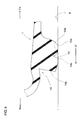
Fig. 1 is a cross sectional view of a motorcycle tire as an embodiment of the present invention. -
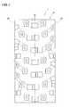
Fig. 2 is a developed partial view of the tread portion of the motorcycle tire showing a tread pattern. -
Fig. 3 is a closeup of a right-hand part of the tread portion shown inFig. 2 . -
Fig. 4 is a cross sectional view of a middle block taken along line X-X ofFig. 2 schematically showing its deformed state during cornering. -
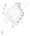
Fig. 5 is a perspective view of a first middle block provided with a long auxiliary groove. -
Fig. 6 is a perspective view of a second middle block provided with a short auxiliary groove. -
Fig. 7 is a developed partial view of a tread portion of a motorcycle tire as another embodiment of the present invention. -
Fig. 8 is a developed partial view of a tread portion of a motorcycle tire as still another embodiment of the present invention. -
Fig. 9 is a developed partial view of a tread portion of a motorcycle tire as a comparative example. - Embodiments of the present invention will now be described in detail in conjunction with the accompanying drawings.
- As shown in
Fig. 1 , amotorcycle tire 1 for rough terrain according to the present invention comprises atread portion 2, a pair ofsidewall portions 3, a pair of axially spacedbead portions 4 each with abead core 5 therein, acarcass 6 extending between thebead portions 4 through thetread portion 2 and thesidewall portions 3, and atread reinforcing layer 7 disposed radially outside thecarcass 6 in thetread portion 2. - As a characteristic of a motorcycle tire, the
tread portion 2 is convexly curved so that thetread face 2a between thetread edges 2t is curved like an arc swelling radially outwardly, and the maximum cross sectional width of thetire 1 occurs between thetread edges 2t. - Between the
tread edges 2t of thedeveloped tread surface 2a, the developed tread width TW is defined. - The
carcass 6 in this example is composed of asingle ply 6A of carcass cords arranged radially at an angle in a range of from 75 to 90 degrees, preferably 80 to 90 degrees with respect to the tire equator C, and theply 6A extends between thebead portions 4 through thetread portion 2 andsidewall portions 3 and is turned up around thebead core 5 in each bead portion to form a pair of turned upportions 6b and amain portion 6a therebetween. For the carcass cords, organic fiber cords, for example, nylon, polyester, rayon and the like are suitably used. - Each
bead portion 4 is provided between themain portion 6a and the turned upportion 6b with abead apex rubber 8 made of hard rubber. - The
tread reinforcing layer 7 is composed of at least one ply, in this example, only oneply 7A of reinforcing cords laid at an angle in a range of from 5 to 40 degrees with respect to the tire equator C. For the reinforce cords, for example, steel cords, aramid cords, rayon cords and the like are suitably used. - As shown in
Fig. 2 , thetread portion 2 is imaginary axially divided into
a crown region Ca which is centered on the tire equator C and has a developed axial width of 1/3 of the developed tread width TW,
a pair of shoulder regions Sa each of which extends axially inwardly from one of thetread edges 2t and has a developed axial width of 1/6 of the developed tread width TW, and
a pair of middle regions Ma between the crown region Ca and the respective shoulder regions Sa each having a developed axial width of 1/6 of the developed tread width TW. - The tread portion contacts with the ground mainly in the crown region Ca during straight running and during cornering at small camber angles. The shoulder region Sa contacts with the ground during cornering at large camber angles. The middle region Ma contacts with the ground during cornering at small camber angles and large camber angles.
- The
tread portion 2 is provided withblocks top surface 16 of a block, ablock 10 whose centroid is positioned within a middle region Ma is called "middle block", ablock 11 whose centroid is positioned within the crown region Ca is called "crown block", and ablock 12 whose centroid is positioned within a shoulder region Sa is called "shoulder block". - The
tread portion 2 may be provided with so called tie bar connecting between the adjacent blocks (10, 11, 12). In such case, if a tie bar has a height of less than 50 % of the height of the connected blocks the tie bar is considered as a separate part from the blocks. If a tie bar has a height of 50 % or more of the height of the connected blocks, the tie bar is considered as a part of the connected blocks. In other words, the tie bar and the connected blocks are considered as one block - As shown in
Fig. 3 , the ground contactingtop surface 16 of eachmiddle block 10 has a maximum width Wa in the tire axial direction which is preferably in a range of from 10 % to 25 % of the developed tread width TW.
If the maximum width Wa is less than 10 % of the developed tread width TW, the rigidity of themiddle block 10 is decreased and it becomes difficult to improve the cornering performance. If the maximum width Wa is more than 25 % of the developed tread width TW, the groove volume among the blocks is decreased, and further digging of the blocks into the ground surface in rough terrain decreases, therefore, there is a possibility that the running performance in rough terrain is deteriorated. - The ground contacting
top surface 16 of eachmiddle block 10 is provided in a central region with anauxiliary groove 13 extending in the tire circumferential direction. There is no void (groove) in the axiallyinner block part 10a defined as being axially inside theauxiliary groove 13 and the axiallyouter block part 10b defined as being axially outside theauxiliary groove 13. - As show in
Fig. 4 , during cornering, themiddle block 10 is subjected to a centrifugal force cf toward the tire equator. Therefore, themiddle block 10 is deformed so that theblock edge 10e and theedge 13e of theauxiliary groove 13 dig into the ground R to generate a large frictional force. As a result, the cornering performance can be improved. Further, the lateral stiffness of themiddle block 10 is reduced by theauxiliary groove 13, side skid suddenly occurred during cornering can be prevented. - As shown in
Fig. 3 , theauxiliary groove 13 is disposed such that acenter line 13c of theauxiliary groove 13 in its widthwise direction is positioned within a central region Cp defined as extending in the tire axial direction between 1/3 and 2/3 of the maximum axial width Wa of themiddle block 10. In this embodiment, theauxiliary groove 13 is disposed within the central region Cp in substance, and no groove is formed outside the central region Cp in order to prevent the rigidity of themiddle block 10 from becoming unbalanced between theblock parts - Therefore, the width W of the
auxiliary groove 13 is preferably in a range of from 15 % to 35 % of the maximum width Wa of themiddle block 10. - As shown in
Fig. 1 , the groove depth D of theauxiliary groove 13 is preferably in a range of from 15 % to 35 % of the height H of themiddle block 10. - If the depth D is more than 35 % of the height H, the rigidity of both
block parts middle block 10 becomes decreased, and the deformation of theblock parts edges 13e of theauxiliary groove 13 becomes decreased, and there is a possibility that the frictional force is decreased. - In this embodiment, the
auxiliary grooves 13 include longauxiliary grooves 14 having a longer circumferential length and shortauxiliary grooves 15 having a shorter circumferential length.
Since eachmiddle block 10 is provided with only oneauxiliary groove 13, the middle blocks 10 include firstmiddle blocks 10A each provided with a longauxiliary groove 14, and second middle blocks 10B each provided with a shortauxiliary groove 15. - Each of the long
auxiliary grooves 14 has circumferential ends 14t, at least one of which is opened at the sidewall of the firstmiddle block 10A.
In this example, both circumferential ends 14t are opened so that the deformation of each of theblock parts - The long
auxiliary groove 14 in this example has a constant groove width w1 so that theblock parts edges 14e is maintained to generate a large frictional force.
Further, the longauxiliary groove 14 in this example extends straight in parallel with the tire circumferential direction so that mud, small objects and the like entered in the longauxiliary groove 14 are easily self ejected during running and theauxiliary groove 14 can effectively exert its edge effect. - As shown in
Fig. 5 , the longauxiliary groove 14 has a pair ofopposite groove walls 18, a groove bottom 17 in which the maximum groove depth occurs, and anarc part 19 smoothly connecting between eachgroove wall 18 and thegroove bottom 17. In the cross section of the longauxiliary groove 14, eachgroove wall 18 is straight, and eacharc part 19 is a circular arc. Preferably, thearc parts 19 has a radius of curvature r1 of 1 to 6 mm in order to avoid a stress concentration. In this example, the groove bottom 17 extends along the entire length of the groove, but it has substantially no extent in the groove's widthwise direction. Accordingly, the groove bottom 17 is a deepest point in the cross section, and the twoarc parts 19 form a single circular arc.
It is also possible that the groove bottom 17 has a certain extent in the groove's widthwise direction. - As shown in
Fig. 3 , both ends in the tire circumferential direction of the shortauxiliary groove 15 are closed so that the deformation of theblock parts middle block 10B is provided with high rigidity. Further, the groove can grip the ground during cornering at small camber angles. - In this example, the short
auxiliary groove 15 hasgroove edges 15e substantially parallel withblock edges 20 of the secondmiddle block 10B. In other words, the contour shape of the shortauxiliary groove 15 in the ground contactingtop surface 16 is similar to the contour shape of the ground contactingtop surface 16 in order to maintain the rigidity of the secondmiddle block 10B. - It is preferable that, as shown in
Fig. 6 , the shortauxiliary groove 15 has a groove depth D2 less than the groove depth D1 of the longauxiliary groove 14 in order to maintain the high rigidity of the secondmiddle block 10B and improve the grip during cornering at small camber angles.
Preferably, the groove depth D2 is set in a range of from 40 % to 60 % of the groove depth D1. - In the short
auxiliary groove 15 in this example, in order to further improve the grip, anangled corner 15c is formed between itsgroove bottom 15b andgroove wall 15a, namely, an arc part smoothly connecting therebetween is not formed although an arc part may be formed similarly to the longauxiliary groove 14. - In this embodiment, as shown in
Fig. 2 , the number N2 of the secondmiddle blocks 10B is more than the number N1 of the first middle blocks 10A. Preferably, the number N2 is 1.5 to 2.5 times (in this example, 2 times) the number N1 in order that the cornering performance is not largely altered if the camber angle is widely changed. - As shown in
Fig. 2 , the above-mentioned crown blocks 11 are provided in their ground contactingtop surfaces 11a withauxiliary grooves 25 extending in the tire circumferential direction so that mud, small objects and the like entered in the longauxiliary groove 14 are easily self ejected during running. In this embodiment, eachauxiliary groove 25 is disposed along the tire equator C so that a motorcycle rider can smoothly stably initiate a cornering or turning operation during straight running. - In this embodiment, the crown blocks 11 include
large crown blocks 11A whose maximum axial width wb is largest, small crown blocks 11B whose maximum axial width wb is smallest, and middle crown blocks 11C whose maximum width wb is less than the largest width and more than the smallest width. Thelarge crown blocks 11A and the middle crown blocks 11C are each provided with a widerauxiliary groove 25 whose both ends are opened, and the small crown blocks 11B are each provided with a narrowauxiliary groove 25 whose both ends are opened. - The above-mentioned
shoulder blocks 12 are provided in their ground contactingtop surfaces 12a withauxiliary grooves 28.
In this embodiment, eachauxiliary groove 28 is not opened at the block sidewall and hasedges 28e substantially parallel withblock edges 12e of theshoulder block 12 on which the concernedauxiliary groove 28 is formed.
Theauxiliary groove 28 can grip the ground during cornering at larger camber angles, while maintaining the rigidity of theshoulder block 12, therefore, the cornering performance on rough terrain can be further improved. - Motorcycle tires having the internal structure shown in
Fig. 1 were experimentally manufactured and tested the cornering performance.
Specifications of the test tires are shown in Table 1.
Other specifications were identical.
tire size: 120/80-19 (rim: 2.15X19)
developed tread width TW: 172 mm
middle blocks' height H: 16.0 mm - Each test tire (tire pressure 80 kPa) was mounted on a rear wheel of a 450cc motocross bike, and
during running in a motocross course, a test rider evaluated cornering performance into ten ranks based on the handle response, rigid feeling and grip.
The results are shown in Table 1, wherein the larger the rank number, the better the performance.Table 1 Tire Ref.1 Ex.1 Ex.2 Ex.3 Ex.4 Ex.5 Ex.6 Ex.7 Ex.8 Ex.9 Ex.10 Ex.11 Ex.12 Ex.13 Ex.14 Ex.15 tread pattern (Fig. no.) 9 1 1 1 1 1 1 1 1 1 1 1 1 1 7 8 long auxiliary groove depth D1/H (%) -- 25 10 15 35 40 25 25 25 25 25 25 25 25 25 25 short auxiliary groove depth D2/H (%) 20 auxiliary groove width W/TW (%) -- 25 25 25 25 25 10 15 35 40 25 25 25 25 25 25 groove number ratio N2/N1 -- 2.0 2.0 2.0 2.0 2.0 2.0 2.0 2.0 2.0 1.0 1.5 2.5 3.0 -- -- cornering performance @ small camber angle 5 9 9 9 9 9 9 9 9 9 8 8 9 9 8 7 @ middle camber angle 5 9 8 9 9 8 8 9 9 8 8 9 9 8 7 7 @ large camber angle 5 9 8 9 9 8 8 9 9 8 9 9 8 8 7 7
Claims (10)
- A motorcycle tire for rough terrain comprising
a tread portion which is,
when an axial developed width of the tread portion from the tire equator to each tread edge is trisected into an axially inner crown region, an axially outer shoulder region and a middle region therebetween,
provided with middle blocks in the middle regions,
wherein each middle block provided in its ground contacting top surface with an auxiliary groove extending in the tire circumferential direction. - The motorcycle tire for rough terrain according to claim 1, wherein the depth of each auxiliary groove is in a range of from 15 % to 35 % of the height of the middle block.
- The motorcycle tire for rough terrain according to claim 1 or 2, wherein the auxiliary grooves include those having both circumferential ends opened.
- The motorcycle tire for rough terrain according to any one of claims 1-3, wherein each auxiliary groove is disposed in a central region of the ground contacting top surface so that a center line of the auxiliary groove in its widthwise direction is positioned within the central region which is defined as having a constant axial width and extending between 1/3 and 2/3 of the maximum axial width of the ground contacting top surface.
- The motorcycle tire for rough terrain according to any one of claims 1-4, wherein the groove width of each auxiliary groove is 15 % to 35 % of the maximum axial width of the ground contacting top surface.
- The motorcycle tire for rough terrain according to any one of claims 1-5, wherein the maximum axial width of the ground contacting top surface of each middle block is 10 % to 25 % of a developed tread width of the tread portion between the tread edges.
- The motorcycle tire for rough terrain according to any one of claims 1-6, wherein the auxiliary groove has, in its cross section,
a pair of groove walls extending straight radially inwardly from the ground contacting top surface,
a groove bottom in which the maximum groove depth occurs, and
an arc part smoothly connecting between each groove wall and the groove bottom. - The motorcycle tire for rough terrain according to claim 7, wherein the arc parts has a radius of curvature of 1 to 6 mm.
- The motorcycle tire for rough terrain according to any one of claims 1-8, wherein the auxiliary grooves include those having a constant groove width.
- The motorcycle tire for rough terrain according to any one of claims 1-9, wherein the auxiliary grooves include those extending straight in parallel with the tire circumferential direction.
Applications Claiming Priority (1)
| Application Number | Priority Date | Filing Date | Title |
|---|---|---|---|
| JP2014124616A JP5986601B2 (en) | 2014-06-17 | 2014-06-17 | Motorcycle tires for running on rough terrain |
Publications (2)
| Publication Number | Publication Date |
|---|---|
| EP2965926A1 true EP2965926A1 (en) | 2016-01-13 |
| EP2965926B1 EP2965926B1 (en) | 2019-10-02 |
Family
ID=53365782
Family Applications (1)
| Application Number | Title | Priority Date | Filing Date |
|---|---|---|---|
| EP15169583.0A Active EP2965926B1 (en) | 2014-06-17 | 2015-05-28 | Motorcycle tire for rough terrain |
Country Status (4)
| Country | Link |
|---|---|
| US (1) | US9975384B2 (en) |
| EP (1) | EP2965926B1 (en) |
| JP (1) | JP5986601B2 (en) |
| CN (1) | CN105270098B (en) |
Cited By (3)
| Publication number | Priority date | Publication date | Assignee | Title |
|---|---|---|---|---|
| EP3047982A1 (en) * | 2015-01-26 | 2016-07-27 | Sumitomo Rubber Industries Limited | Motorcycle tire for running on rough terrain |
| CN110789277A (en) * | 2018-08-01 | 2020-02-14 | 住友橡胶工业株式会社 | Tire for running on rough terrain |
| EP3611037A1 (en) * | 2018-08-17 | 2020-02-19 | Sumitomo Rubber Industries, Ltd. | Tyre for running on rough terrain |
Families Citing this family (9)
| Publication number | Priority date | Publication date | Assignee | Title |
|---|---|---|---|---|
| US10065457B2 (en) | 2016-07-05 | 2018-09-04 | Shinji Marui | Tire with offset beveled knobs |
| CN106739839B (en) * | 2016-12-01 | 2018-11-02 | 厦门正新橡胶工业有限公司 | A kind of mountain bike pattern structure on tire tread |
| JP7087427B2 (en) * | 2018-02-08 | 2022-06-21 | 住友ゴム工業株式会社 | Motorcycle tires |
| JP7056392B2 (en) * | 2018-06-13 | 2022-04-19 | 住友ゴム工業株式会社 | tire |
| JP7110784B2 (en) * | 2018-07-19 | 2022-08-02 | 住友ゴム工業株式会社 | tire |
| USD856903S1 (en) * | 2018-07-30 | 2019-08-20 | Sumitomo Rubber Industries, Ltd. | Tire for motorcycle |
| JP7135599B2 (en) * | 2018-08-29 | 2022-09-13 | 住友ゴム工業株式会社 | Motorcycle tires for rough terrain |
| JP7163784B2 (en) * | 2019-01-16 | 2022-11-01 | 住友ゴム工業株式会社 | tires for rough terrain |
| USD981941S1 (en) * | 2021-02-19 | 2023-03-28 | Sumitomo Rubber Industries, Ltd. | Tire for motorcycle |
Citations (4)
| Publication number | Priority date | Publication date | Assignee | Title |
|---|---|---|---|---|
| EP2374636A1 (en) * | 2008-12-18 | 2011-10-12 | Bridgestone Corporation | Tire for motorcycle |
| JP2012025307A (en) | 2010-07-26 | 2012-02-09 | Sumitomo Rubber Ind Ltd | Motorcycle tire for running on rough terrain |
| EP2529954A1 (en) * | 2011-05-30 | 2012-12-05 | Sumitomo Rubber Industries, Ltd. | Tread pattern of an off-road motorcycle tire |
| EP2657048A1 (en) * | 2012-04-27 | 2013-10-30 | Sumitomo Rubber Industries, Ltd. | Pneumatic tire for running on rough terrain |
Family Cites Families (14)
| Publication number | Priority date | Publication date | Assignee | Title |
|---|---|---|---|---|
| JPS5572404A (en) * | 1978-11-27 | 1980-05-31 | Bridgestone Corp | Moto-cross tire for motor-cycle |
| JPS60199702A (en) * | 1984-03-26 | 1985-10-09 | Sumitomo Rubber Ind Ltd | Tire for motorcycle |
| JPS60236808A (en) * | 1984-05-09 | 1985-11-25 | Sumitomo Rubber Ind Ltd | Tyre for light vehicle |
| JPS6367304U (en) * | 1986-10-22 | 1988-05-06 | ||
| JP3021723B2 (en) * | 1991-03-25 | 2000-03-15 | 株式会社ブリヂストン | Off-road tires for motorcycles |
| JP2009179109A (en) * | 2008-01-29 | 2009-08-13 | Bridgestone Corp | Pneumatic tire |
| JP5154972B2 (en) * | 2008-02-19 | 2013-02-27 | 株式会社ブリヂストン | Pneumatic tires for motorcycles |
| JP4510906B2 (en) * | 2008-05-08 | 2010-07-28 | 住友ゴム工業株式会社 | Pneumatic tire |
| JP5346600B2 (en) * | 2009-01-19 | 2013-11-20 | 株式会社ブリヂストン | Tires for motorcycles |
| JP5081264B2 (en) * | 2010-03-01 | 2012-11-28 | 住友ゴム工業株式会社 | Pneumatic tire |
| JP5237986B2 (en) * | 2010-05-28 | 2013-07-17 | 住友ゴム工業株式会社 | Motorcycle tires for running on rough terrain |
| JP5161933B2 (en) * | 2010-07-28 | 2013-03-13 | 住友ゴム工業株式会社 | Motorcycle tires for running on rough terrain |
| JP5647642B2 (en) * | 2012-04-09 | 2015-01-07 | 住友ゴム工業株式会社 | Pneumatic tire for running on rough terrain |
| CN203485682U (en) * | 2013-08-26 | 2014-03-19 | 厦门正新橡胶工业有限公司 | Tread pattern structure of motorcycle pneumatic tyre for desert racing motocross |
-
2014
- 2014-06-17 JP JP2014124616A patent/JP5986601B2/en active Active
-
2015
- 2015-05-28 EP EP15169583.0A patent/EP2965926B1/en active Active
- 2015-06-04 US US14/730,515 patent/US9975384B2/en active Active
- 2015-06-10 CN CN201510315493.2A patent/CN105270098B/en active Active
Patent Citations (4)
| Publication number | Priority date | Publication date | Assignee | Title |
|---|---|---|---|---|
| EP2374636A1 (en) * | 2008-12-18 | 2011-10-12 | Bridgestone Corporation | Tire for motorcycle |
| JP2012025307A (en) | 2010-07-26 | 2012-02-09 | Sumitomo Rubber Ind Ltd | Motorcycle tire for running on rough terrain |
| EP2529954A1 (en) * | 2011-05-30 | 2012-12-05 | Sumitomo Rubber Industries, Ltd. | Tread pattern of an off-road motorcycle tire |
| EP2657048A1 (en) * | 2012-04-27 | 2013-10-30 | Sumitomo Rubber Industries, Ltd. | Pneumatic tire for running on rough terrain |
Cited By (5)
| Publication number | Priority date | Publication date | Assignee | Title |
|---|---|---|---|---|
| EP3047982A1 (en) * | 2015-01-26 | 2016-07-27 | Sumitomo Rubber Industries Limited | Motorcycle tire for running on rough terrain |
| US10562354B2 (en) | 2015-01-26 | 2020-02-18 | Sumitomo Rubber Industries, Ltd. | Motorcycle tire for running on rough terrain |
| CN110789277A (en) * | 2018-08-01 | 2020-02-14 | 住友橡胶工业株式会社 | Tire for running on rough terrain |
| EP3611037A1 (en) * | 2018-08-17 | 2020-02-19 | Sumitomo Rubber Industries, Ltd. | Tyre for running on rough terrain |
| US11458773B2 (en) | 2018-08-17 | 2022-10-04 | Sumitomo Rubber Industries, Ltd. | Tyre for running on rough terrain |
Also Published As
| Publication number | Publication date |
|---|---|
| US20150360517A1 (en) | 2015-12-17 |
| EP2965926B1 (en) | 2019-10-02 |
| JP2016002885A (en) | 2016-01-12 |
| CN105270098B (en) | 2019-04-19 |
| US9975384B2 (en) | 2018-05-22 |
| CN105270098A (en) | 2016-01-27 |
| JP5986601B2 (en) | 2016-09-06 |
Similar Documents
| Publication | Publication Date | Title |
|---|---|---|
| EP2965926B1 (en) | Motorcycle tire for rough terrain | |
| EP3000621B1 (en) | Pneumatic tire | |
| EP2952362B1 (en) | Pneumatic tire | |
| EP3015287B1 (en) | Pneumatic tire | |
| EP2695750B1 (en) | Pneumatic tire for running on rough terrain | |
| EP2732982B1 (en) | Pneumatic tire | |
| EP2998129B1 (en) | Pneumatic tire for off-road motorcycle | |
| EP2423006B1 (en) | Motorcycle tire for running on rough terrain | |
| EP2762334B1 (en) | Motorcycle tire for running on rough terrain | |
| EP3088211B1 (en) | Motorcycle pneumatic tire | |
| EP2634014A1 (en) | Motorcycle tire | |
| EP2664465B1 (en) | Pneumatic tire for running on rough terrain | |
| EP2546079B1 (en) | Motorcycle tire for running on rough terrain | |
| EP3050720B1 (en) | Pneumatic motorcycle tire | |
| US9630455B2 (en) | Pneumatic tire for running on rough terrain | |
| US11654720B2 (en) | Tire | |
| EP3028876B1 (en) | Tire for motorbike | |
| US10173473B2 (en) | Pneumatic motorcycle tire | |
| EP3318419A1 (en) | Tire and three-wheeled vehicle with the same | |
| EP3199378B1 (en) | Pneumatic tire | |
| EP3597451B1 (en) | Tyre |
Legal Events
| Date | Code | Title | Description |
|---|---|---|---|
| PUAI | Public reference made under article 153(3) epc to a published international application that has entered the european phase |
Free format text: ORIGINAL CODE: 0009012 |
|
| AK | Designated contracting states |
Kind code of ref document: A1 Designated state(s): AL AT BE BG CH CY CZ DE DK EE ES FI FR GB GR HR HU IE IS IT LI LT LU LV MC MK MT NL NO PL PT RO RS SE SI SK SM TR |
|
| AX | Request for extension of the european patent |
Extension state: BA ME |
|
| 17P | Request for examination filed |
Effective date: 20160314 |
|
| RBV | Designated contracting states (corrected) |
Designated state(s): AL AT BE BG CH CY CZ DE DK EE ES FI FR GB GR HR HU IE IS IT LI LT LU LV MC MK MT NL NO PL PT RO RS SE SI SK SM TR |
|
| STAA | Information on the status of an ep patent application or granted ep patent |
Free format text: STATUS: EXAMINATION IS IN PROGRESS |
|
| 17Q | First examination report despatched |
Effective date: 20181122 |
|
| RIC1 | Information provided on ipc code assigned before grant |
Ipc: B60C 11/03 20060101AFI20190508BHEP Ipc: B60C 11/11 20060101ALI20190508BHEP |
|
| GRAP | Despatch of communication of intention to grant a patent |
Free format text: ORIGINAL CODE: EPIDOSNIGR1 |
|
| STAA | Information on the status of an ep patent application or granted ep patent |
Free format text: STATUS: GRANT OF PATENT IS INTENDED |
|
| INTG | Intention to grant announced |
Effective date: 20190716 |
|
| GRAS | Grant fee paid |
Free format text: ORIGINAL CODE: EPIDOSNIGR3 |
|
| GRAA | (expected) grant |
Free format text: ORIGINAL CODE: 0009210 |
|
| STAA | Information on the status of an ep patent application or granted ep patent |
Free format text: STATUS: THE PATENT HAS BEEN GRANTED |
|
| AK | Designated contracting states |
Kind code of ref document: B1 Designated state(s): AL AT BE BG CH CY CZ DE DK EE ES FI FR GB GR HR HU IE IS IT LI LT LU LV MC MK MT NL NO PL PT RO RS SE SI SK SM TR |
|
| REG | Reference to a national code |
Ref country code: GB Ref legal event code: FG4D |
|
| REG | Reference to a national code |
Ref country code: CH Ref legal event code: EP Ref country code: AT Ref legal event code: REF Ref document number: 1185775 Country of ref document: AT Kind code of ref document: T Effective date: 20191015 |
|
| REG | Reference to a national code |
Ref country code: IE Ref legal event code: FG4D |
|
| REG | Reference to a national code |
Ref country code: DE Ref legal event code: R096 Ref document number: 602015038938 Country of ref document: DE |
|
| REG | Reference to a national code |
Ref country code: NL Ref legal event code: MP Effective date: 20191002 |
|
| REG | Reference to a national code |
Ref country code: LT Ref legal event code: MG4D |
|
| REG | Reference to a national code |
Ref country code: AT Ref legal event code: MK05 Ref document number: 1185775 Country of ref document: AT Kind code of ref document: T Effective date: 20191002 |
|
| PG25 | Lapsed in a contracting state [announced via postgrant information from national office to epo] |
Ref country code: AT Free format text: LAPSE BECAUSE OF FAILURE TO SUBMIT A TRANSLATION OF THE DESCRIPTION OR TO PAY THE FEE WITHIN THE PRESCRIBED TIME-LIMIT Effective date: 20191002 Ref country code: SE Free format text: LAPSE BECAUSE OF FAILURE TO SUBMIT A TRANSLATION OF THE DESCRIPTION OR TO PAY THE FEE WITHIN THE PRESCRIBED TIME-LIMIT Effective date: 20191002 Ref country code: NL Free format text: LAPSE BECAUSE OF FAILURE TO SUBMIT A TRANSLATION OF THE DESCRIPTION OR TO PAY THE FEE WITHIN THE PRESCRIBED TIME-LIMIT Effective date: 20191002 Ref country code: PL Free format text: LAPSE BECAUSE OF FAILURE TO SUBMIT A TRANSLATION OF THE DESCRIPTION OR TO PAY THE FEE WITHIN THE PRESCRIBED TIME-LIMIT Effective date: 20191002 Ref country code: LT Free format text: LAPSE BECAUSE OF FAILURE TO SUBMIT A TRANSLATION OF THE DESCRIPTION OR TO PAY THE FEE WITHIN THE PRESCRIBED TIME-LIMIT Effective date: 20191002 Ref country code: ES Free format text: LAPSE BECAUSE OF FAILURE TO SUBMIT A TRANSLATION OF THE DESCRIPTION OR TO PAY THE FEE WITHIN THE PRESCRIBED TIME-LIMIT Effective date: 20191002 Ref country code: PT Free format text: LAPSE BECAUSE OF FAILURE TO SUBMIT A TRANSLATION OF THE DESCRIPTION OR TO PAY THE FEE WITHIN THE PRESCRIBED TIME-LIMIT Effective date: 20200203 Ref country code: FI Free format text: LAPSE BECAUSE OF FAILURE TO SUBMIT A TRANSLATION OF THE DESCRIPTION OR TO PAY THE FEE WITHIN THE PRESCRIBED TIME-LIMIT Effective date: 20191002 Ref country code: GR Free format text: LAPSE BECAUSE OF FAILURE TO SUBMIT A TRANSLATION OF THE DESCRIPTION OR TO PAY THE FEE WITHIN THE PRESCRIBED TIME-LIMIT Effective date: 20200103 Ref country code: NO Free format text: LAPSE BECAUSE OF FAILURE TO SUBMIT A TRANSLATION OF THE DESCRIPTION OR TO PAY THE FEE WITHIN THE PRESCRIBED TIME-LIMIT Effective date: 20200102 Ref country code: BG Free format text: LAPSE BECAUSE OF FAILURE TO SUBMIT A TRANSLATION OF THE DESCRIPTION OR TO PAY THE FEE WITHIN THE PRESCRIBED TIME-LIMIT Effective date: 20200102 Ref country code: LV Free format text: LAPSE BECAUSE OF FAILURE TO SUBMIT A TRANSLATION OF THE DESCRIPTION OR TO PAY THE FEE WITHIN THE PRESCRIBED TIME-LIMIT Effective date: 20191002 |
|
| PG25 | Lapsed in a contracting state [announced via postgrant information from national office to epo] |
Ref country code: RS Free format text: LAPSE BECAUSE OF FAILURE TO SUBMIT A TRANSLATION OF THE DESCRIPTION OR TO PAY THE FEE WITHIN THE PRESCRIBED TIME-LIMIT Effective date: 20191002 Ref country code: HR Free format text: LAPSE BECAUSE OF FAILURE TO SUBMIT A TRANSLATION OF THE DESCRIPTION OR TO PAY THE FEE WITHIN THE PRESCRIBED TIME-LIMIT Effective date: 20191002 Ref country code: IS Free format text: LAPSE BECAUSE OF FAILURE TO SUBMIT A TRANSLATION OF THE DESCRIPTION OR TO PAY THE FEE WITHIN THE PRESCRIBED TIME-LIMIT Effective date: 20200224 Ref country code: CZ Free format text: LAPSE BECAUSE OF FAILURE TO SUBMIT A TRANSLATION OF THE DESCRIPTION OR TO PAY THE FEE WITHIN THE PRESCRIBED TIME-LIMIT Effective date: 20191002 |
|
| PG25 | Lapsed in a contracting state [announced via postgrant information from national office to epo] |
Ref country code: AL Free format text: LAPSE BECAUSE OF FAILURE TO SUBMIT A TRANSLATION OF THE DESCRIPTION OR TO PAY THE FEE WITHIN THE PRESCRIBED TIME-LIMIT Effective date: 20191002 |
|
| REG | Reference to a national code |
Ref country code: DE Ref legal event code: R097 Ref document number: 602015038938 Country of ref document: DE |
|
| PG2D | Information on lapse in contracting state deleted |
Ref country code: IS |
|
| PG25 | Lapsed in a contracting state [announced via postgrant information from national office to epo] |
Ref country code: RO Free format text: LAPSE BECAUSE OF FAILURE TO SUBMIT A TRANSLATION OF THE DESCRIPTION OR TO PAY THE FEE WITHIN THE PRESCRIBED TIME-LIMIT Effective date: 20191002 Ref country code: DK Free format text: LAPSE BECAUSE OF FAILURE TO SUBMIT A TRANSLATION OF THE DESCRIPTION OR TO PAY THE FEE WITHIN THE PRESCRIBED TIME-LIMIT Effective date: 20191002 Ref country code: EE Free format text: LAPSE BECAUSE OF FAILURE TO SUBMIT A TRANSLATION OF THE DESCRIPTION OR TO PAY THE FEE WITHIN THE PRESCRIBED TIME-LIMIT Effective date: 20191002 Ref country code: IS Free format text: LAPSE BECAUSE OF FAILURE TO SUBMIT A TRANSLATION OF THE DESCRIPTION OR TO PAY THE FEE WITHIN THE PRESCRIBED TIME-LIMIT Effective date: 20200202 |
|
| PLBE | No opposition filed within time limit |
Free format text: ORIGINAL CODE: 0009261 |
|
| STAA | Information on the status of an ep patent application or granted ep patent |
Free format text: STATUS: NO OPPOSITION FILED WITHIN TIME LIMIT |
|
| PG25 | Lapsed in a contracting state [announced via postgrant information from national office to epo] |
Ref country code: IT Free format text: LAPSE BECAUSE OF FAILURE TO SUBMIT A TRANSLATION OF THE DESCRIPTION OR TO PAY THE FEE WITHIN THE PRESCRIBED TIME-LIMIT Effective date: 20191002 Ref country code: SK Free format text: LAPSE BECAUSE OF FAILURE TO SUBMIT A TRANSLATION OF THE DESCRIPTION OR TO PAY THE FEE WITHIN THE PRESCRIBED TIME-LIMIT Effective date: 20191002 Ref country code: SM Free format text: LAPSE BECAUSE OF FAILURE TO SUBMIT A TRANSLATION OF THE DESCRIPTION OR TO PAY THE FEE WITHIN THE PRESCRIBED TIME-LIMIT Effective date: 20191002 |
|
| 26N | No opposition filed |
Effective date: 20200703 |
|
| PG25 | Lapsed in a contracting state [announced via postgrant information from national office to epo] |
Ref country code: SI Free format text: LAPSE BECAUSE OF FAILURE TO SUBMIT A TRANSLATION OF THE DESCRIPTION OR TO PAY THE FEE WITHIN THE PRESCRIBED TIME-LIMIT Effective date: 20191002 |
|
| PG25 | Lapsed in a contracting state [announced via postgrant information from national office to epo] |
Ref country code: CH Free format text: LAPSE BECAUSE OF NON-PAYMENT OF DUE FEES Effective date: 20200531 Ref country code: MC Free format text: LAPSE BECAUSE OF FAILURE TO SUBMIT A TRANSLATION OF THE DESCRIPTION OR TO PAY THE FEE WITHIN THE PRESCRIBED TIME-LIMIT Effective date: 20191002 Ref country code: LI Free format text: LAPSE BECAUSE OF NON-PAYMENT OF DUE FEES Effective date: 20200531 |
|
| REG | Reference to a national code |
Ref country code: BE Ref legal event code: MM Effective date: 20200531 |
|
| GBPC | Gb: european patent ceased through non-payment of renewal fee |
Effective date: 20200528 |
|
| PG25 | Lapsed in a contracting state [announced via postgrant information from national office to epo] |
Ref country code: LU Free format text: LAPSE BECAUSE OF NON-PAYMENT OF DUE FEES Effective date: 20200528 |
|
| PG25 | Lapsed in a contracting state [announced via postgrant information from national office to epo] |
Ref country code: IE Free format text: LAPSE BECAUSE OF NON-PAYMENT OF DUE FEES Effective date: 20200528 Ref country code: GB Free format text: LAPSE BECAUSE OF NON-PAYMENT OF DUE FEES Effective date: 20200528 |
|
| PG25 | Lapsed in a contracting state [announced via postgrant information from national office to epo] |
Ref country code: BE Free format text: LAPSE BECAUSE OF NON-PAYMENT OF DUE FEES Effective date: 20200531 |
|
| PG25 | Lapsed in a contracting state [announced via postgrant information from national office to epo] |
Ref country code: TR Free format text: LAPSE BECAUSE OF FAILURE TO SUBMIT A TRANSLATION OF THE DESCRIPTION OR TO PAY THE FEE WITHIN THE PRESCRIBED TIME-LIMIT Effective date: 20191002 Ref country code: MT Free format text: LAPSE BECAUSE OF FAILURE TO SUBMIT A TRANSLATION OF THE DESCRIPTION OR TO PAY THE FEE WITHIN THE PRESCRIBED TIME-LIMIT Effective date: 20191002 Ref country code: CY Free format text: LAPSE BECAUSE OF FAILURE TO SUBMIT A TRANSLATION OF THE DESCRIPTION OR TO PAY THE FEE WITHIN THE PRESCRIBED TIME-LIMIT Effective date: 20191002 |
|
| PG25 | Lapsed in a contracting state [announced via postgrant information from national office to epo] |
Ref country code: MK Free format text: LAPSE BECAUSE OF FAILURE TO SUBMIT A TRANSLATION OF THE DESCRIPTION OR TO PAY THE FEE WITHIN THE PRESCRIBED TIME-LIMIT Effective date: 20191002 |
|
| REG | Reference to a national code |
Ref country code: FR Ref legal event code: PLFP Year of fee payment: 9 |
|
| P01 | Opt-out of the competence of the unified patent court (upc) registered |
Effective date: 20230510 |
|
| PGFP | Annual fee paid to national office [announced via postgrant information from national office to epo] |
Ref country code: FR Payment date: 20230411 Year of fee payment: 9 Ref country code: DE Payment date: 20230404 Year of fee payment: 9 |