EP2965594B1 - Verfahren zur erzeugung eines elektrischen lichtbogens mit direkter räumlicher, thermischer und mechanischer wirkung auf material und vorrichtung zur erzeugung eines elektrischen lichtbogens dazu - Google Patents
Verfahren zur erzeugung eines elektrischen lichtbogens mit direkter räumlicher, thermischer und mechanischer wirkung auf material und vorrichtung zur erzeugung eines elektrischen lichtbogens dazu Download PDFInfo
- Publication number
- EP2965594B1 EP2965594B1 EP14718791.8A EP14718791A EP2965594B1 EP 2965594 B1 EP2965594 B1 EP 2965594B1 EP 14718791 A EP14718791 A EP 14718791A EP 2965594 B1 EP2965594 B1 EP 2965594B1
- Authority
- EP
- European Patent Office
- Prior art keywords
- electric arc
- generating
- magnetic field
- arc
- electrodes
- Prior art date
- Legal status (The legal status is an assumption and is not a legal conclusion. Google has not performed a legal analysis and makes no representation as to the accuracy of the status listed.)
- Active
Links
Images


Classifications
-
- E—FIXED CONSTRUCTIONS
- E21—EARTH OR ROCK DRILLING; MINING
- E21B—EARTH OR ROCK DRILLING; OBTAINING OIL, GAS, WATER, SOLUBLE OR MELTABLE MATERIALS OR A SLURRY OF MINERALS FROM WELLS
- E21B7/00—Special methods or apparatus for drilling
- E21B7/14—Drilling by use of heat, e.g. flame drilling
- E21B7/15—Drilling by use of heat, e.g. flame drilling of electrically generated heat
-
- H—ELECTRICITY
- H05—ELECTRIC TECHNIQUES NOT OTHERWISE PROVIDED FOR
- H05H—PLASMA TECHNIQUE; PRODUCTION OF ACCELERATED ELECTRICALLY-CHARGED PARTICLES OR OF NEUTRONS; PRODUCTION OR ACCELERATION OF NEUTRAL MOLECULAR OR ATOMIC BEAMS
- H05H1/00—Generating plasma; Handling plasma
- H05H1/24—Generating plasma
- H05H1/26—Plasma torches
- H05H1/32—Plasma torches using an arc
- H05H1/34—Details, e.g. electrodes, nozzles
- H05H1/40—Details, e.g. electrodes, nozzles using applied magnetic fields, e.g. for focusing or rotating the arc
-
- H—ELECTRICITY
- H05—ELECTRIC TECHNIQUES NOT OTHERWISE PROVIDED FOR
- H05H—PLASMA TECHNIQUE; PRODUCTION OF ACCELERATED ELECTRICALLY-CHARGED PARTICLES OR OF NEUTRONS; PRODUCTION OR ACCELERATION OF NEUTRAL MOLECULAR OR ATOMIC BEAMS
- H05H1/00—Generating plasma; Handling plasma
- H05H1/24—Generating plasma
- H05H1/48—Generating plasma using an arc
- H05H1/50—Generating plasma using an arc and using applied magnetic fields, e.g. for focusing or rotating the arc
Definitions
- the invention concerns generating an electric arc which acts directly areally thermally and mechanically on the material and the device for generating the electric arc, intended for use mainly in material disintegration and drilling in geological formations.
- thermal plasma generators have been known since the 40s in their non-transferred as well as transferred arc form (melting furnaces in metallurgy). State of the art is comprehensively treated in the monograph Thermal plasma torches Design, Characteristics, Applications edited by M.F. Zukov and I.M. Zasypkin with extensive theoretical background.
- Thermal action of an electric arc on the material can be divided into four categories:
- Plasmatrons with non-transferred arc generate heat flow in the plasma (torch) with temperatures about 5-6000 K.
- the transferred arc reaches temperatures up to 15-20 thousand K, at high pressure (up to 1000 bar) 50-60 thousand K, with a significantly higher radiating (radiation) performance.
- Heat treatment of materials by an electric arc has a long history, from the mid-19th century, when this phenomenon was discovered. The possibility of generating high temperatures of up to several-fold 10 thousand °K has been examined.
- the first application of plasma was melting metal in electric arc furnaces, which represented a revolutionary change compared to hydrocarbon fuel furnaces.
- the implementation method for the plasma reactor in the U.S. Pat.7727460 uses two electrodes, independent of the processed material, to implement the transferred arc that vaporizes the material.
- the closest in nature to the present patent is material vaporization by a transferred arc in order to create micro or nano particles.
- Described systems share one common feature, which is also their drawback, that is the evaporated material forms the material of the anode consumed, where one of the transferred arc roots is located.
- the principal value of innovation in such power sources lies in time transforming of the power storage (set of capacitors or inductances) charging process. Charging takes time several orders longer than discharging the energy stored. For example, charging for one second by 1 kW source and discharging of the stored energy for 1 millisecond leads to electric discharge with instantaneous power of 1 MW. Discharging during shorter time interval, for example 1 microsecond, allows to focus the energy into instantaneous power of 1 GW.
- This principle can be used also for generating high power by electro-hydraulic phenomenon or when generating electromagnetic fields of high intensity.
- Existing conventional plasmatrons do not allow for the use of such extreme power outputs.
- the laser beam is essentially a point source of heat and to cover the whole area of the borehole it is necessary to blur the beam, which significantly decreases its power density (W/m2), or to scan the beam across the whole surface with, and thereby decrease the power supplied per unit area by 2-3 orders.
- important reference source is the use of milimeter electromagnetic waves to melt or vaporize the rocks for purposes of drilling, disclosed in the article: "(1) Annual Report 2009, Millimeter Wave Deep Drilling For Geothermal Energy, Natural Gas and Oil MITEI Seed Fund Program, Paul Woskov and Daniel Cohn, MIT Plasma Science and Fusion Center 167 Albany Street, NW16-110, Cambridge, MA 02139.
- Electro-hydraulic phenomenon based on electrical discharge in an aqueous medium with the subsequent pressure shock wave, acts with an extreme pressure action on close objects. Applications of this phenomenon in rock breaking or, respectively, forming sheet metal as alternatives to hydraulic pressing process are known. Electro-hydraulic phenomenon has high efficiency in an aquatic environment and its effectiveness decreases in gas environment for the reason of differences in viscosity of environments on the order of magnitude. Conventional plasmatrons do not allow for utilization of this phenomenon.
- thermal plasma A special category of thermal plasma are plasmatrons, where the plasma gas is a water vapour, in certain cases even water that turns to steam in the device.
- the first experiments with an electric arc and water were done by H. Gerdien, A. Lotz Wiss. Vero Stammungen Siemenswerk 2, 489, 1922 , and later H. Maecker. Zeitschrift fuer Physik 129, 108-122, 1951 and particularly Hrabovsk ⁇ et al., IEEE Trans. on Plasma Science 3, 1993 .
- the study discloses the creation of magnetic nozzle for plasma stream with power in Gigawatt and supersonic speeds.
- the research used cumulative source with a single pulse of 1.6 MJ to generate large currents up to 3.10 exp5 A.
- the magnetic nozzle concept has been successfully applied in demanding aerospace applications.
- This solution forms the heat source shape with necessary properties of homogeneity and sufficient surface cover for heat flow generation.
- This work also presents replacement of the arc model with a cylindrical solid body, to be used in simulation modelling of the arc movement in a viscous environment.
- Sweep movement of arc roots on the circular electrode surface contributes significantly to lengthening their life.
- Electric field between the electrodes is an insignificant component of the forces acting on the arc when compared to the forces induced by an external magnetic field.
- the present solution focuses mainly on improving the transfer efficiency from electric power up to transfer of heat energy into the rock.
- the properties of electric arc have not yet been employed in direct areal material disintegration in close proximity to the electric arc.
- the present invention eliminates the deficiencies and disadvantages of the processes described in the prior art and is the basis to the use of transferred electric arcs for the purposes of drilling in geological formations.
- Transferred electrical arc creates a homogeneous heat flow and acts directly on the material so that at least part of the electric arc is pressed by action of forces against the surface of the material to be disrupted.
- the electric arc is produced in a spark gap and formed into the desired shape between the electrodes of the diffuser.
- the direct action of an electric arc means action with minimizing intermediating plasma medium, which provides the heat transfer between arc and the material to be disrupted.
- Plasma medium is contained in the working medium which is fed into the device to fulfil following purposes: cooling the device, acting with force on the electric arc and being the source of plasma medium necessary for arc burning.
- energy in the electric arc passes into the medium which itself acts on the material to be disrupted.
- Solution according to the present invention lies in taking and shaping the arc and its direct action on the material to be disrupted.
- the electric arc is formed and guided in such manner that a substantial part of the electric arc is pushed out and moving outside the space of the generator.
- Part of the conducting electric arc channel is by shaping and guiding placed near the surface of material to be disrupted. This part of the conductive channel is in a moving state. It is preferred that at least part of the transferred electric arc is shaped such that at least part the conductive channel of the electric arc has the shape of a spiral which rotates in a specified disc-shaped space, and is movable in an axial direction.
- the conductive channel's spiral shape is formed by the action of magnetic forces and/or fluid flow forces.
- Hydro-mechanical forces are created by the interaction of smoothly expanding working medium with an electric arc and by their action guide the electric arc.
- the magnetic fields and hydrodynamic forces acting on the electric arc, and also the electrode geometry preferably interact in such manner that they increase the heat-exposed surface of the electrodes on which the roots of the electric arc move.
- the electrode has the shape of the diffuser, because this shape increases the area through which working medium flows.
- Magnetic field located before the region where the cathode narrows by curving, resp. its axial part, has an orientation opposite to the axial part of the magnetic field in the diffuser.
- High magnetic field intensity in the spark gap protects the spark gap area by spinning intensely and pushing the electric arc out of the spark gap and protecting it against melting.
- the magnetic field acts on the electric arc in such manner that the arc root on the electrodes moves in a circular path.
- the concurrent actions of the magnetic field and the hydrodynamic forces on the electric arc has to be such that the direction of the resulting force points towards the material to be disrupted and this resulting force presses the formed electric arc into close proximity of the material to be disrupted.
- the electric arc can be moved along the surface shaped as a circular ring, wherein circular ring's symmetry axis is identical to the symmetry axis of the whole device.
- a power pulse can be fed into the electric arc in working mode and working in gaseous or aqueous medium to generate pressure shock wave.
- Electric arc prior to the introduction of power pulse can be induced into contraction to amplify the pressure shock wave.
- radiation component of the electric arc's heat flow directed into the device is reflected by reflecting surfaces towards the material to be disrupted, that is in the direction in which the electric arc is transferred.
- the part of electric arc that is situated near the cathode is stabilized in such way that the axis of symmetry of the part of the electric arc is parallel to the axis of the device, so as to widen to maximum the active, spiral part of the electric arc.
- An electric arc shaped as a spiral rotating under the influence of magnetic field and hydrodynamic forces acts by centrifugal forces on the material located in the space between the device and material to be disrupted, and thus material is removed from this area. Cooling medium supplied to the surface of electrodes protects the parts of electrodes exposed to heat.
- cathode's own magnetic field force action amplifies force effect of magnetic field on the electric arc.
- Increasing the magnetic field intensity can be achieved by increasing the speed of rotation of the electric arc spiral, which will increase the centrifugal forces and action on the material in the space defined by the spiral motion.
- the primary attributes of generator used to generate the electric arc acting areally on the treated material:
- the system allows to use pressure shock waves and pumping caused by rotating spiral of the electric arc to transport rocks away from the place of disintegration. This eliminates removal of rocks by means of water jet (hydromagmatic phenomenon), which cools down and slows the drilling process.
- Transferring the major part an electric arc outside the electric arc generating device's space substantially reduces demands on thermal resistance of the used construction materials and the device space stays cooler, which increases longevity of the device.
- the device for generating an electric arc contains the following essential elements: axially symmetrical electrodes, that is an anode and an cathode, a spark gap, nozzles for the working medium flow, cooling media inlet and outlet, electric power supply, ring-shaped magnets whose section has the shape of a triangle and the anode has the shape of the diffuser with an angular span from 5 ° into 130°.
- the anode in the shape of the diffuser performs the following purposes:
- the arc root uniformly moves along the inner side of the anode ensuring so even thermal load on the significant part of the electrode.
- Radii of the electrodes' curvature are not less than 2 mm in order to maintain the correct geometry of lines of force of electric field and limit local electric field amplification.
- the shape of the anode also enables effective interaction of the arc column with the fluid medium flow.
- the electrode surface also reflects the radiative heat flow directed into the device back into the area with material to be disrupted.
- the cathode may for example be in the shape of a truncated cone. This electrode is used for arc discharge.
- the distinctive shape of the electrode ensures the stabilization of arc discharge's root in such manner that close to the electrode flow causes a negative pressure, which stabilizes arc's root in the area of reduced pressure.
- Ring-shaped magnets with triangular cross-section ensure with their distinctive shape presence of magnetic field needed to rotate the arc discharge roots and at the same time causing movement in the axial direction.
- Nozzles for the flow of working medium have two main functions: the interaction of the flow of working medium with the arc intensifies motion effects caused by the magnetic field acting on the arc discharge (an increase in the speed of rotation and more intense movement in the axial direction). They supply the necessary amount of plasma medium into the arc channel.
- a spark gap is used to initialize the electrical discharge and is positioned as shown in Fig. 1 , 2 . Electric discharge is immediately after its formation pushed out by the fluid flow against the action of the local magnetic field into the device's working area.
- the spark gap also serves as the nozzle for plasma medium entry.
- Diffuser is bounded by the anode itself and the treated rock, to which at least a part of the electric arc is approaching.
- the primary function of the diffuser is to homogenize the temperature field on the boundary between the device and the treated rock.
- the device for generating an electric arc further contains electromagnets designed to create time-variable component of the magnetic field.
- the device may contain functional elements providing protection to exposed body parts of the generator, especially electrodes, from thermal overload.
- Surface of the electrodes is made of porous ceramics which by coolant supply performs protective function by creating a protective water film on the surface of the electrodes.
- Electrode surface also contains shape and design features that create reflective surfaces of the electrodes that reflect and direct the heat flow towards the material to be disrupted. It is preferred that at least a part of the anode and/or cathode is covered with a layer of reflective material. Because of the heat resistance and directed thermal conductivity when cooling the electrodes, the electrodes are made of composite materials (Cu-W, etc.), which is advantageous in terms of their service life.
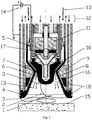
- Example of embodiment is shown in Fig. 1
- Electric discharge is initiated in the spark gap 7 , with the ignition voltage on the power supply 14 ranging from 0 to 10 kV.
- a spark gap 7 is positioned so that it is possible by means of working medium 13 to overcome the magnetic forces and push out the discharge 1 , 2 into the device diffuser chamber.
- Electric arc 1 , 2 consisting of the spiral active part 1 and an axial part 2 , is stabilized in the device diffuser by two dominant forces. Lorentz force, due to presence of magnetic field generated by the permanent magnets 9, 11 .
- the size and direction of the magnetic field generated by permanent magnets causes movement of the arc in tangential direction, while also stabilizing electric arc roots 3 on the edge of the anode 4 as well as the cathode 6 .
- Force induced by the fluid flow 13 amplifies the tangential movement that induced by Lorentz force, but mainly causes movement of the electric arc 1 , 2 in an axial direction.
- Geometry of the cathode 6 is designed such that the fluid flow 13 consisting of the working medium causes reduction in pressure at the edge of the cathode 6 , whereby like the magnetic field it stabilizes the root 3 of the electric arc 1 , 2 , which is thus moving in a circle at the edge of the cathode 6 .
- Axial part of the electric arc 2 is stabilized near the axis of the device in the vicinity of the cathode 6 .
- the anode geometry 4 allows the flowing medium to achieve relatively high speeds near the surface 10 of the anode 4 .
- the arc discharge is pushed out to the edge of the anode 4 towards the treated material 15 .
- the root 3 of the electric arc moves in a circle along the extended part of the anode 4 .
- Stabilized electric arc 1 shaped as a spiral, rotates in close proximity to the material to be disrupted 15 . But the heat transfers from the electric arc into components of the device are because of significantly larger distances smaller on the order of magnitude than the heat transfers into the material to be disrupted.
- the arc spiral 1 works at the same time as a centrifugal pump and removes the evaporated and melted fragments of the disrupted rock in the radial direction out of the device working area.
- the entire device is cooled with a layered structure of the anode 4 and the cathode 6 and the device casing with parallel supply of cooling media 12 .
- Plasma medium 13 is supplied centrally into the spark gap 7 using nozzles 5 .
- FIG. 2 This example realization is shown in Fig. 2 .
- An electric discharge is initiated in a spark gap 7 , with the ignition voltage on the power supply 14 ranging from 0 to 10 kV.
- the spark gap 7 is positioned so that it is possible by means of working medium 13 to overcome the magnetic forces and push out the electric arc 1 , 2 into the device diffuser chamber. Both parts of the electric arc 1 , 2 , are stabilized in the device diffuser by two dominant forces.
- the Lorentz force induced by the presence of a magnetic field generated by permanent magnets 9 , 11 and electromagnets 16 , 17 .
- the size and direction of the magnetic field generated by the permanent magnets causes movement of the arc in tangential direction, while stabilizing the electric arc roots 3 on the edge of the anode 4 as well as the cathode 6 .
- Force induced by the fluid flow 13 amplifies the tangential movement induced by the Lorentz force, but mainly moves the electric arc 2 in an axial direction.
- the geometry of the cathode 6 is designed such that the fluid flow of the working medium 13 causes a reduction in pressure at the edge of the cathode 6 , whereby like the magnetic field it stabilizes the electric arc root 3 , which thus moves in a circle at the edge of cathode 6 .
- the anode 4 geometry allows the flowing medium to achieve relatively high speeds near the surface 10 of the anode 4 .
- the electric arc 1 is pushed out to the edge of the anode 4 towards the treated material 15 .
- the electric arc's root 3 moves in a circle along the widened part of the anode 4 .
- the arc 1 , 2 can be moved in an axial direction by action of the magnetic field generated by electromagnets 16 , 17 .
- Components of the magnetic field generated by electromagnets 16 , 17 are not constant over time and the fed in power pulses allow relatively rapid changes in direction and size of the total magnetic field intensity.
- Disclosed changes in the magnetic field cause rapid changes in the movement of the electric arc 2 and thus contribute to the formation of pressure shock wave through electro-hydraulic phenomenon and thereby contribute to the process of disintegration and removal of disrupted rock outside the device space.
- the electric arc is brought into contraction prior to the introduction of power pulse.
- the passage of pressure shock wave initiated by electro-hydraulic phenomenon causes in the vicinity of electric arc reduction in density of the working medium, but its presence at the original density is then renewed by feeding in the new working medium 13 .
- Stabilized electric arc 1 shaped as a spiral, rotates in close proximity to the material to be disrupted 15. But the heat transfers from the electric arc into components of the device are because of the significantly larger distances smaller on the order of magnitude than the heat transfers into the material to be disrupted.
- the arc spiral 1 works at the same time as a centrifugal pump and removes the evaporated and melted fragments of the disrupted rock in the radial direction from the device working area.
- the entire device is cooled with a layered structure with parallel power supply 12 .
- Plasma medium 13 is supplied centrally using nozzles 5 .
- Both electrodes of the generator are made of porous ceramics which performs a protective function by supplying coolant supply and creating protective water film on the surface of the electrodes 8 . Electrode surface also contains shape and design features that create reflective surfaces that reflect and direct the heat flow towards material to be disrupted 15 .
- the anode 4 and the cathode 6 are at the edges where the root 3 of the electric arc 1 , 2 moves and is stabilized, and the electrodes are made of a Cu-W composite for better heat resistance and directed thermal conductivity during their cooling, which helps to prolong their life.
Landscapes
- Engineering & Computer Science (AREA)
- Physics & Mathematics (AREA)
- Plasma & Fusion (AREA)
- Spectroscopy & Molecular Physics (AREA)
- Life Sciences & Earth Sciences (AREA)
- Geology (AREA)
- Mining & Mineral Resources (AREA)
- Environmental & Geological Engineering (AREA)
- Fluid Mechanics (AREA)
- General Life Sciences & Earth Sciences (AREA)
- Geochemistry & Mineralogy (AREA)
- Plasma Technology (AREA)
Claims (21)
- Verfahren zur Erzeugung eines Lichtbogens durch thermische und mechanische Einwirkungen auf das Material, wobei der Bogen zwischen zwei eine axialsymmetrische Elektrodenanordnung bildenden Elektroden (4, 6) gebildet wird, wobei die Anode (4) in die Form eines Diffusors mit einer Winkelspanne von 5° bis 130° konfiguriert ist, und der Bogen in einer Funkenstrecke (7) im verengten Teil des Diffusors erzeugt wird, wobei der Lichtbogen durch die Wirkung eines Magnetfeldes geformt und gerichtet wird, das aus einem externen Magnetfeld, das durch ringförmige, Dreieckquerschnittform aufweisende Magnete erzeugt wird, und aus elektrischem Feld des Bogens selbst und aus hydromechanischen Kräften, die durch Zusammenwirken eines kontinuierlich expandierenden Arbeitsmediums mit dem Lichtbogen entstehen, besteht in solcher Weise, dass:- der wesentliche Teil des Lichtbogens direkt und flächig auf das zu zerstörende leitfähige und / oder nicht leitfähige Material wirkt,- der wesentliche Teil des Wärmestroms aus dem Lichtbogen in das zu zerstörende Material gerichtet wird,- zumindest ein Teil des Lichtbogens in eine Spiralform geformt wird,wobei sich die beiden Lichtbogenwurzeln (3) über die Oberflächen der genannten Elektroden (4, 6) bewegen.
- Verfahren zur Erzeugung eines Lichtbogens nach Anspruch 1, dadurch gekennzeichnet, dass der Lichtbogen auch so geformt und gerichtet wird, dass sich durch Wechselwirkung vom Magnetfeld und von hydromechanischen Kräften das wesentliche Teil des Lichtbogens bewegt und außerhalb des Raumes der Elektrodenanordnung in die Richtung des zu zerstörenden Materials gerichtet und gedrückt wird.
- Verfahren zur Erzeugung eines Lichtbogens nach einem der Ansprüche 1 bis 2, dadurch gekennzeichnet, dass die Elektrodenanordnung die Form eines Diffusors aufweist, sodass sie eine Vergrößerung der von dem Arbeitsmedium durchgeströmten Fläche gewährleistet, und die genannte Elektrodenanordnung mit dem Magnetfeld und den hydromechanischen Kräften zusammenwirkt, und damit die wärmeexponierte Elektrodenoberfläche vergrößert wird, über die sich die Lichtbogenwurzeln bewegen.
- Verfahren zur Erzeugung eines Lichtbogens nach einem der Ansprüche 1 bis 3, dadurch gekennzeichnet, dass das Magnetfeld und die hydrodynamischen Kräfte durch ihre charakteristische Parameter derart eingestellt werden, dass durch ihre Wirkung auf den Lichtbogen ein Teil des Lichtbogens in der Nähe der Vorrichtungsachse in der Kathodenumgebung stabilisiert wird, und ein anderer Teil des Lichtbogens parallel zur Vorrichtungsachse ist, um so den aktiven, spiralförmigen Teil des Lichtbogens über die zu zerstörende Oberfläche auf ein Maximum zu erweitern.
- Verfahren zur Erzeugung eines Lichtbogens nach einem der Ansprüche 1 bis 4, dadurch gekennzeichnet, dass die Verteilung des Magnetfeldes und seine Ausrichtung so konfiguriert sind, dass der Effekt der Kräftewirkung auf den Lichtbogen im verengten Elektrodenteil durch Lokalisierung des Magnetfeldes vor dem Bereich, in dem die Kathode durch Abrunden verengt wird, oder durch Einstellen einer gegenüber der Orientierung des axialen Teils des Magnetfeldes im Diffusor entgegengesetzten Orientierung des axialen Teils des Magnetfeldes, verstärkt wird.
- Verfahren zur Erzeugung eines Lichtbogens nach einem der Ansprüche 1 bis 5, dadurch gekennzeichnet, dass das Intensitätsniveau des Magnetfeldes in Zusammenwirkung mit hydrodynamischen Kräften so erhöht wird, dass eine intensive Kraftwirkung in der Funkenstrecke (7) erzeugt wird, und damit der Lichtbogen gedreht und aus der Funkenstrecke (7) herausgedrückt wird, und somit die Funkenstrecke (7) gegen Schmelzen geschützt wird.
- Verfahren zur Erzeugung eines Lichtbogens nach einem der Ansprüche 1 bis 6, dadurch gekennzeichnet, dass das Magnetfeld auf den Lichtbogen derart einwirkt, dass sich die Bogenwurzel auf den Elektroden kreisförmig bewegt.
- Verfahren zur Erzeugung eines Lichtbogens nach einem der Ansprüche 1 bis 7, dadurch gekennzeichnet, dass ein Teil des als Spirale geformten Lichtbogens in einem scheibenförmigen Raum rotiert und in axialer Richtung bewegbar ist.
- Verfahren zur Erzeugung eines Lichtbogens nach einem der Ansprüche 1 bis 8, dadurch gekennzeichnet, dass sich der Lichtbogen entlang einer kreisringförmigen Fläche bewegt, wobei die Symmetrieachse des Kreisrings mit der Symmetrieachse der Elektrodenanordnung identisch ist.
- Verfahren zur Erzeugung eines Lichtbogens nach einem der Ansprüche 1 bis 9, dadurch gekennzeichnet, dass ein Leistungsimpuls in den in der Betriebsart im gasförmigen oder wässrigen Medium arbeitenden Lichtbogen zwecks Druckstoßwellenerzeugung zugeführt wird, wobei das Lichtbogen vorzugsweise vor der Einführung des genannten Leistungsimpulses in eine Kontraktion eingeleitet wird.
- Verfahren zur Erzeugung eines Lichtbogens nach einem der Ansprüche 1 bis 10, dadurch gekennzeichnet, dass nach dem Durchgang der durch das elektrohydraulische Phänomen eingeleiteten Druckstoßwelle, wobei in der Nähe des Lichtbogens zur Reduktion der Dichte des Arbeitsmediums kommt, die ursprüngliche Dichte des Arbeitsmediums durch Zuführen von weiterem Arbeitsmedium wiederhergestellt wird.
- Verfahren zur Erzeugung eines Lichtbogens nach einem der Ansprüche 1 bis 11, dadurch gekennzeichnet, dass die in die Elektrodenanordnung gerichtete Strahlungskomponente des Wärmestroms des Lichtbogens durch die Reflexionsflächen der Anordnung mit hohem Reflexionsgrad und Wärmebeständigkeit reflektiert wird, und damit der Energiefluss zu dem zu zerstörenden Material in der Richtung erhöht wird, in der der Lichtbogen übertragen wird.
- Verfahren zur Erzeugung eines Lichtbogens nach einem der Ansprüche 1 bis 12, dadurch gekennzeichnet, dass durch Zusammenwirkung des Magnetfeldes und der hydrodynamischen Kräfte die Bogenwurzel bei der Anodenelektrode zu der Außenkante der Anode gedrückt wird, um den aktiven Teil des Lichtbogens möglichst zu erweitern.
- Verfahren zur Erzeugung eines Lichtbogens nach einem der Ansprüche 1 bis 13, dadurch gekennzeichnet, dass der Lichtbogen in Form von einer unter dem Einfluss des Magnetfeldes und der hydrodynamischen Kräfte rotierenden Spirale auf das in dem Bereich zwischen der Elektrodenanordnung und dem zu zerstörenden Material vorliegende Material durch Zentrifugalkräfte einwirkt, und somit das Material aus diesem Bereich entfernt wird.
- Verfahren zur Erzeugung eines Lichtbogens nach einem der Ansprüche 1 bis 14, dadurch gekennzeichnet, dass das an die Oberfläche der Elektroden zugeführte Kühlmedium die thermisch exponierten Teile der Elektroden schützt.
- Verfahren zur Erzeugung eines Lichtbogens nach einem der Ansprüche 1 bis 15, dadurch gekennzeichnet, dass die Rotationsgeschwindigkeit der Lichtbogenspirale durch Erhöhung der Magnetfeldintensität erhöht wird, und hiermit die Zentrifugalkräfte und die Einwirkung auf das Material im durch die Spiralbewegung begrenzten Bereich erhöht werden, durch Platzieren eines Magneten in den Bereich der Kathodenelektrode.
- Vorrichtung zur Erzeugung eines Lichtbogens durch thermische und mechanische Einwirkungen auf das Material, wobei die genannte Vorrichtung eine axialsymmetrische Elektrodenanordnung umfasst, d.h. eine Anode (4) und eine Kathode (6), Düsen (5) für den Arbeitsmediumstrom, Zu- und Ableitung (12) der Kühlmedien, elektrische Stromversorgung (14), dadurch gekennzeichnet, dass die Anode (4) in die Form eines Diffusors mit einer Winkelspanne von 5° bis 130° konfiguriert ist, und die Vorrichtung weiter eine Funkenstrecke (7) im verengten Teil des Diffusors und ringförmige Dreieckquerschnittform aufweisende Magnete (9) aufweist.
- Vorrichtung zur Erzeugung des Lichtbogens nach Anspruch 17, dadurch gekennzeichnet, dass sie weiter Permanentmagnete (11) umfasst, wobei die Magnete (9) und die Permanentmagnete (11) innerhalb der Elektrodenanordnung (4, 6) angeordnet sind.
- Vorrichtung zur Erzeugung des Lichtbogens nach einem der Ansprüche 17 und 18, dadurch gekennzeichnet, dass sie weiter Elektromagneten (16, 17) umfasst, die dazu bestimmt sind, eine zeitvariable Komponente des Magnetfeldes zu erzeugen.
- Vorrichtung zur Erzeugung des Lichtbogens nach einem der Ansprüche 17 bis 19, dadurch gekennzeichnet, dass zumindest ein Teil der Innenfläche (8) der Anode (4) und / oder der Kathode (6) mit einer Schicht eines reflektierenden Materials bedeckt ist.
- Vorrichtung zur Erzeugung des Lichtbogens nach einem der Ansprüche 17 bis 20, dadurch gekennzeichnet, dass die Teile der Elektroden (4, 6) aus Verbundwerkstoffen, beispielsweise Cu-W, und die thermisch exponierte Teile (8) der Elektroden (4, 6) aus poröser Keramik bestehen.
Applications Claiming Priority (2)
| Application Number | Priority Date | Filing Date | Title |
|---|---|---|---|
| SK50006-2013A SK500062013A3 (sk) | 2013-03-05 | 2013-03-05 | Generovanie elektrického oblúka, ktorý priamo plošne tepelne a mechanicky pôsobí na materiál a zariadenie na generovanie elektrického oblúka |
| PCT/SK2014/050006 WO2014137299A1 (en) | 2013-03-05 | 2014-03-04 | Generating electric arc, which directly areally thermally and mechanically acts on material, and device for generating electric arc |
Publications (2)
| Publication Number | Publication Date |
|---|---|
| EP2965594A1 EP2965594A1 (de) | 2016-01-13 |
| EP2965594B1 true EP2965594B1 (de) | 2018-01-10 |
Family
ID=51491697
Family Applications (1)
| Application Number | Title | Priority Date | Filing Date |
|---|---|---|---|
| EP14718791.8A Active EP2965594B1 (de) | 2013-03-05 | 2014-03-04 | Verfahren zur erzeugung eines elektrischen lichtbogens mit direkter räumlicher, thermischer und mechanischer wirkung auf material und vorrichtung zur erzeugung eines elektrischen lichtbogens dazu |
Country Status (6)
| Country | Link |
|---|---|
| US (2) | US10094171B2 (de) |
| EP (1) | EP2965594B1 (de) |
| DK (1) | DK2965594T3 (de) |
| ES (1) | ES2667523T3 (de) |
| SK (1) | SK500062013A3 (de) |
| WO (1) | WO2014137299A1 (de) |
Families Citing this family (22)
| Publication number | Priority date | Publication date | Assignee | Title |
|---|---|---|---|---|
| US9779915B2 (en) * | 2013-12-11 | 2017-10-03 | Applied Plasma Inc Co., Ltd. | Plasma generating device comprising a rotating body |
| WO2015116343A1 (en) * | 2014-01-31 | 2015-08-06 | Harry Bailey Curlett | Method and system for subsurface resource production |
| US9713243B2 (en) * | 2014-10-31 | 2017-07-18 | California Institute Of Technology | Toroidal plasma systems |
| SK500792014A3 (sk) | 2014-12-23 | 2016-09-05 | Ga Drilling, A. S. | Spôsob odstraňovania materiálov ich dezintegráciou pôsobením elektrickej plazmy |
| WO2017127659A1 (en) | 2016-01-20 | 2017-07-27 | Baker Hughes Incorporated | Electrical pulse drill bit having spiral electrodes |
| US10584585B2 (en) | 2016-11-15 | 2020-03-10 | Arcbyt, Inc. | Tunneling for underground power and pipelines |
| US10731441B2 (en) * | 2016-12-14 | 2020-08-04 | Saudi Arabian Oil Company | Induced cavitation to prevent scaling on wellbore pumps |
| KR102646623B1 (ko) * | 2017-01-23 | 2024-03-11 | 에드워드 코리아 주식회사 | 플라즈마 발생 장치 및 가스 처리 장치 |
| KR102686242B1 (ko) | 2017-01-23 | 2024-07-17 | 에드워드 코리아 주식회사 | 질소 산화물 감소 장치 및 가스 처리 장치 |
| CN107072028A (zh) * | 2017-06-28 | 2017-08-18 | 衢州昀睿工业设计有限公司 | 利用冷却水力旋转电极的装置 |
| WO2019245545A1 (en) * | 2018-06-20 | 2019-12-26 | Halliburton Energy Services, Inc. | System and method for determining formation characteristics using electrical arc modeling |
| AU2018438150A1 (en) * | 2018-11-14 | 2020-05-28 | Arcbyt, Inc. | Tunneling for Underground Power and Pipelines |
| CN110856329A (zh) * | 2019-12-11 | 2020-02-28 | 西安空天能源动力智能制造研究院有限公司 | 一种耐烧蚀的高热效率等离子体炬及其使用方法 |
| US12188353B2 (en) * | 2020-08-28 | 2025-01-07 | Halliburton Energy Services, Inc. | Plasma chemistry derived relation between arc and spark for pulse power drilling |
| US11591909B2 (en) | 2021-01-12 | 2023-02-28 | EarthGrid PBC | Tunnel boring system |
| US11136886B1 (en) | 2021-01-12 | 2021-10-05 | EarthGrid PBC | Tunnel boring system |
| US11994016B2 (en) | 2021-12-09 | 2024-05-28 | Saudi Arabian Oil Company | Downhole phase separation in deviated wells |
| CN115007974B (zh) * | 2022-04-19 | 2024-03-08 | 上海工程技术大学 | 电弧负压力约束的钨极氩弧焊接方法 |
| CN114713942B (zh) * | 2022-04-19 | 2024-03-08 | 上海工程技术大学 | 电弧负压力约束的钨极氩弧增材制造方法 |
| CN116001033A (zh) * | 2022-12-28 | 2023-04-25 | 江苏康迅数控装备科技有限公司 | 一种六面钻机头作业用微观应力改善装置 |
| CN116608735B (zh) * | 2023-07-20 | 2023-09-22 | 吉林市双林射孔器材有限责任公司 | 一种扩孔射孔弹 |
| CN119466590B (zh) * | 2025-01-15 | 2025-03-21 | 中国石油大学(华东) | 一种具有集束冲击喷嘴的等离子体钻头及钻井方法 |
Citations (1)
| Publication number | Priority date | Publication date | Assignee | Title |
|---|---|---|---|---|
| WO2014098776A2 (en) * | 2012-12-17 | 2014-06-26 | Ga Drilling, A. S. | Multimodal rock disintegration by thermal effect and system for performing the method |
Family Cites Families (25)
| Publication number | Priority date | Publication date | Assignee | Title |
|---|---|---|---|---|
| US1898926A (en) | 1931-02-02 | 1933-02-21 | Walter Franciscus Cornelis Baa | Method of making bore holes |
| US2868950A (en) | 1956-11-13 | 1959-01-13 | Union Carbide Corp | Electric metal-arc process and apparatus |
| US2979449A (en) | 1958-12-05 | 1961-04-11 | Sheer Korman Associates | Carbothermic reduction of metal oxides |
| US3082314A (en) | 1959-04-20 | 1963-03-19 | Shin Meiwa Kogyo Kabushiki Kai | Plasma arc torch |
| US3396806A (en) | 1964-07-28 | 1968-08-13 | Physics Internat Company | Thermal underground penetrator |
| US3453488A (en) * | 1965-05-20 | 1969-07-01 | Xerox Corp | Plasma arc electrodes |
| US3467206A (en) | 1967-07-07 | 1969-09-16 | Gulf Research Development Co | Plasma drilling |
| US3693731A (en) | 1971-01-08 | 1972-09-26 | Atomic Energy Commission | Method and apparatus for tunneling by melting |
| US3944778A (en) | 1974-05-14 | 1976-03-16 | David Grigorievich Bykhovsky | Electrode assembly of plasmatron |
| US4055741A (en) | 1975-12-08 | 1977-10-25 | David Grigorievich Bykhovsky | Plasma arc torch |
| US4391339A (en) | 1978-08-04 | 1983-07-05 | Hydronautics, Incorporated | Cavitating liquid jet assisted drill bit and method for deep-hole drilling |
| US4626648A (en) * | 1985-07-03 | 1986-12-02 | Browning James A | Hybrid non-transferred-arc plasma torch system and method of operating same |
| JP2659807B2 (ja) | 1989-01-26 | 1997-09-30 | 万鎔工業株式会社 | 直接製錬方法 |
| DE3914617A1 (de) | 1989-05-03 | 1990-11-08 | Werner Foppe | Vorrichtungen und verfahren zur gewaehrleistung kontinuierlich ablaufender schmelzbohrprozesse fuer tiefbohrungen |
| US5220150A (en) * | 1991-05-03 | 1993-06-15 | Regents Of The University Of Minnesota | Plasma spray torch with hot anode and gas shroud |
| RU2038475C1 (ru) | 1992-04-03 | 1995-06-27 | Санкт-Петербургский государственный горный институт им.Г.В.Плеханова (технический университет) | Способ электротермомеханического бурения и устройство для его осуществления |
| US5771984A (en) | 1995-05-19 | 1998-06-30 | Massachusetts Institute Of Technology | Continuous drilling of vertical boreholes by thermal processes: including rock spallation and fusion |
| US5801489A (en) | 1996-02-07 | 1998-09-01 | Paul E. Chism, Jr. | Three-phase alternating current plasma generator |
| TW469757B (en) * | 1999-12-13 | 2001-12-21 | Nippon Steel Corp | A transferred plasma heating anode |
| JP2003522299A (ja) | 2000-02-10 | 2003-07-22 | テトロニクス リミテッド | 微細粉末を製造するためのプラズマアーク反応器 |
| CA2405743C (en) | 2000-04-10 | 2009-09-15 | Tetronics Limited | Twin plasma torch apparatus |
| NO322323B2 (no) | 2003-12-01 | 2016-09-13 | Unodrill As | Fremgangsmåte og anordning for grunnboring |
| JP4373252B2 (ja) * | 2004-03-16 | 2009-11-25 | 浩史 滝川 | プラズマ生成装置 |
| NO326571B1 (no) * | 2005-06-16 | 2009-01-12 | Sinvent As | Fremgangsmate og reaktor for fremstilling av karbon nanoror |
| DE102011053106B4 (de) * | 2011-02-25 | 2016-03-24 | Industrieanlagen-Betriebsgesellschaft Mbh | Plasmabrenner und Verfahren zum Bearbeiten von Werkstücken |
-
2013
- 2013-03-05 SK SK50006-2013A patent/SK500062013A3/sk unknown
-
2014
- 2014-03-04 ES ES14718791.8T patent/ES2667523T3/es active Active
- 2014-03-04 WO PCT/SK2014/050006 patent/WO2014137299A1/en not_active Ceased
- 2014-03-04 EP EP14718791.8A patent/EP2965594B1/de active Active
- 2014-03-04 DK DK14718791.8T patent/DK2965594T3/en active
- 2014-03-04 US US14/773,178 patent/US10094171B2/en not_active Expired - Fee Related
-
2018
- 2018-09-06 US US16/123,689 patent/US20190010761A1/en not_active Abandoned
Patent Citations (1)
| Publication number | Priority date | Publication date | Assignee | Title |
|---|---|---|---|---|
| WO2014098776A2 (en) * | 2012-12-17 | 2014-06-26 | Ga Drilling, A. S. | Multimodal rock disintegration by thermal effect and system for performing the method |
Also Published As
| Publication number | Publication date |
|---|---|
| US20160024849A1 (en) | 2016-01-28 |
| US10094171B2 (en) | 2018-10-09 |
| DK2965594T3 (en) | 2018-03-19 |
| ES2667523T3 (es) | 2018-05-11 |
| WO2014137299A1 (en) | 2014-09-12 |
| SK500062013A3 (sk) | 2014-10-03 |
| US20190010761A1 (en) | 2019-01-10 |
| EP2965594A1 (de) | 2016-01-13 |
Similar Documents
| Publication | Publication Date | Title |
|---|---|---|
| EP2965594B1 (de) | Verfahren zur erzeugung eines elektrischen lichtbogens mit direkter räumlicher, thermischer und mechanischer wirkung auf material und vorrichtung zur erzeugung eines elektrischen lichtbogens dazu | |
| EP2941522B1 (de) | Multimodale gesteinszertrümmerung anhand eines thermischen effekts und vorrichtung zur ausführung der methode | |
| Kalra et al. | Gliding arc in tornado using a reverse vortex flow | |
| Hantzsche | Mysteries of the arc cathode spot: A retrospective glance | |
| US6472632B1 (en) | Method and apparatus for direct electrothermal-physical conversion of ceramic into nanopowder | |
| Kosareva et al. | Remote triggering of air-gap discharge by a femtosecond laser filament and postfilament at distances up to 80 m | |
| Nominé et al. | Synthesis of nanomaterials by electrode erosion using discharges in liquids | |
| Felber et al. | Methods for producing ultrahigh magnetic fields | |
| Cao et al. | Influence of the laminar plasma torch construction on the jet characteristics | |
| US3388291A (en) | Annular magnetic hall current accelerator | |
| SK50622009A3 (sk) | Spôsob rozrušovania materiálov a zariadenie na vykonávanie tohto spôsobu | |
| Winterberg | Lasers for inertial confinement fusion driven by high explosives | |
| Kong et al. | Study on the machining characteristics of high-efficiency mixed gas atomized discharge ablation process of titanium alloy | |
| Anshakov et al. | Electric-arc steam plasma generator | |
| Liu et al. | Underwater electrical wire array explosion: fundamentals, design, and applications | |
| Essiptchouk et al. | Thermal and power characteristics of plasma torch with reverse vortex | |
| Han et al. | Research on the physical characteristics and rock-breaking effect of high-energy plasma drill bit | |
| Yu | Studying the mechanism of electric explosion of metal conductors | |
| Basiev et al. | High-speed ablation of ultradeep channels by a phase-conjugate dynamically controlled passively Q-switched Nd: YAG laser | |
| Peterson | Design and operation of the electrogun, an electrothermal gun for producing metal and carbon plasma jets | |
| Wu et al. | Numerical simulation of the metal bridge foil explosion plasma ignition of B/KNO3 | |
| CN106304594A (zh) | 一种层流等离子发生器 | |
| Boulos et al. | Thermal Arcs | |
| Li et al. | Experimental research on short electric arc milling machining based on the mechanical-fluid coupling effect | |
| Chittenden et al. | Indirect-drive inertial confinement fusion using highly supersonic, radiatively cooled, plasma slugs |
Legal Events
| Date | Code | Title | Description |
|---|---|---|---|
| PUAI | Public reference made under article 153(3) epc to a published international application that has entered the european phase |
Free format text: ORIGINAL CODE: 0009012 |
|
| 17P | Request for examination filed |
Effective date: 20151001 |
|
| AK | Designated contracting states |
Kind code of ref document: A1 Designated state(s): AL AT BE BG CH CY CZ DE DK EE ES FI FR GB GR HR HU IE IS IT LI LT LU LV MC MK MT NL NO PL PT RO RS SE SI SK SM TR |
|
| AX | Request for extension of the european patent |
Extension state: BA ME |
|
| DAX | Request for extension of the european patent (deleted) | ||
| REG | Reference to a national code |
Ref country code: DE Ref legal event code: R079 Ref document number: 602014019822 Country of ref document: DE Free format text: PREVIOUS MAIN CLASS: H05H0001500000 Ipc: E21B0007150000 |
|
| RIC1 | Information provided on ipc code assigned before grant |
Ipc: H05H 1/50 20060101ALI20170301BHEP Ipc: E21B 7/15 20060101AFI20170301BHEP |
|
| GRAP | Despatch of communication of intention to grant a patent |
Free format text: ORIGINAL CODE: EPIDOSNIGR1 |
|
| INTG | Intention to grant announced |
Effective date: 20170418 |
|
| GRAJ | Information related to disapproval of communication of intention to grant by the applicant or resumption of examination proceedings by the epo deleted |
Free format text: ORIGINAL CODE: EPIDOSDIGR1 |
|
| GRAP | Despatch of communication of intention to grant a patent |
Free format text: ORIGINAL CODE: EPIDOSNIGR1 |
|
| INTC | Intention to grant announced (deleted) | ||
| INTG | Intention to grant announced |
Effective date: 20170725 |
|
| GRAS | Grant fee paid |
Free format text: ORIGINAL CODE: EPIDOSNIGR3 |
|
| RIN1 | Information on inventor provided before grant (corrected) |
Inventor name: DVONC, LUKAS Inventor name: HORVATH, GABRIEL Inventor name: KOCIS, IVAN |
|
| GRAA | (expected) grant |
Free format text: ORIGINAL CODE: 0009210 |
|
| AK | Designated contracting states |
Kind code of ref document: B1 Designated state(s): AL AT BE BG CH CY CZ DE DK EE ES FI FR GB GR HR HU IE IS IT LI LT LU LV MC MK MT NL NO PL PT RO RS SE SI SK SM TR |
|
| REG | Reference to a national code |
Ref country code: CH Ref legal event code: EP Ref country code: AT Ref legal event code: REF Ref document number: 962624 Country of ref document: AT Kind code of ref document: T Effective date: 20180115 |
|
| REG | Reference to a national code |
Ref country code: FR Ref legal event code: PLFP Year of fee payment: 5 |
|
| REG | Reference to a national code |
Ref country code: IE Ref legal event code: FG4D |
|
| REG | Reference to a national code |
Ref country code: DE Ref legal event code: R096 Ref document number: 602014019822 Country of ref document: DE |
|
| REG | Reference to a national code |
Ref country code: DK Ref legal event code: T3 Effective date: 20180314 |
|
| REG | Reference to a national code |
Ref country code: NL Ref legal event code: FP |
|
| REG | Reference to a national code |
Ref country code: ES Ref legal event code: FG2A Ref document number: 2667523 Country of ref document: ES Kind code of ref document: T3 Effective date: 20180511 |
|
| REG | Reference to a national code |
Ref country code: SK Ref legal event code: T3 Ref document number: E 26673 Country of ref document: SK |
|
| REG | Reference to a national code |
Ref country code: AT Ref legal event code: MK05 Ref document number: 962624 Country of ref document: AT Kind code of ref document: T Effective date: 20180110 |
|
| REG | Reference to a national code |
Ref country code: NO Ref legal event code: T2 Effective date: 20180110 |
|
| PG25 | Lapsed in a contracting state [announced via postgrant information from national office to epo] |
Ref country code: FI Free format text: LAPSE BECAUSE OF FAILURE TO SUBMIT A TRANSLATION OF THE DESCRIPTION OR TO PAY THE FEE WITHIN THE PRESCRIBED TIME-LIMIT Effective date: 20180110 Ref country code: CY Free format text: LAPSE BECAUSE OF FAILURE TO SUBMIT A TRANSLATION OF THE DESCRIPTION OR TO PAY THE FEE WITHIN THE PRESCRIBED TIME-LIMIT Effective date: 20180110 Ref country code: HR Free format text: LAPSE BECAUSE OF FAILURE TO SUBMIT A TRANSLATION OF THE DESCRIPTION OR TO PAY THE FEE WITHIN THE PRESCRIBED TIME-LIMIT Effective date: 20180110 Ref country code: LT Free format text: LAPSE BECAUSE OF FAILURE TO SUBMIT A TRANSLATION OF THE DESCRIPTION OR TO PAY THE FEE WITHIN THE PRESCRIBED TIME-LIMIT Effective date: 20180110 |
|
| PG25 | Lapsed in a contracting state [announced via postgrant information from national office to epo] |
Ref country code: PL Free format text: LAPSE BECAUSE OF FAILURE TO SUBMIT A TRANSLATION OF THE DESCRIPTION OR TO PAY THE FEE WITHIN THE PRESCRIBED TIME-LIMIT Effective date: 20180110 Ref country code: GR Free format text: LAPSE BECAUSE OF FAILURE TO SUBMIT A TRANSLATION OF THE DESCRIPTION OR TO PAY THE FEE WITHIN THE PRESCRIBED TIME-LIMIT Effective date: 20180411 Ref country code: SE Free format text: LAPSE BECAUSE OF FAILURE TO SUBMIT A TRANSLATION OF THE DESCRIPTION OR TO PAY THE FEE WITHIN THE PRESCRIBED TIME-LIMIT Effective date: 20180110 Ref country code: LV Free format text: LAPSE BECAUSE OF FAILURE TO SUBMIT A TRANSLATION OF THE DESCRIPTION OR TO PAY THE FEE WITHIN THE PRESCRIBED TIME-LIMIT Effective date: 20180110 Ref country code: IS Free format text: LAPSE BECAUSE OF FAILURE TO SUBMIT A TRANSLATION OF THE DESCRIPTION OR TO PAY THE FEE WITHIN THE PRESCRIBED TIME-LIMIT Effective date: 20180510 Ref country code: AT Free format text: LAPSE BECAUSE OF FAILURE TO SUBMIT A TRANSLATION OF THE DESCRIPTION OR TO PAY THE FEE WITHIN THE PRESCRIBED TIME-LIMIT Effective date: 20180110 Ref country code: RS Free format text: LAPSE BECAUSE OF FAILURE TO SUBMIT A TRANSLATION OF THE DESCRIPTION OR TO PAY THE FEE WITHIN THE PRESCRIBED TIME-LIMIT Effective date: 20180110 Ref country code: BG Free format text: LAPSE BECAUSE OF FAILURE TO SUBMIT A TRANSLATION OF THE DESCRIPTION OR TO PAY THE FEE WITHIN THE PRESCRIBED TIME-LIMIT Effective date: 20180410 |
|
| REG | Reference to a national code |
Ref country code: DE Ref legal event code: R097 Ref document number: 602014019822 Country of ref document: DE |
|
| PG25 | Lapsed in a contracting state [announced via postgrant information from national office to epo] |
Ref country code: AL Free format text: LAPSE BECAUSE OF FAILURE TO SUBMIT A TRANSLATION OF THE DESCRIPTION OR TO PAY THE FEE WITHIN THE PRESCRIBED TIME-LIMIT Effective date: 20180110 Ref country code: RO Free format text: LAPSE BECAUSE OF FAILURE TO SUBMIT A TRANSLATION OF THE DESCRIPTION OR TO PAY THE FEE WITHIN THE PRESCRIBED TIME-LIMIT Effective date: 20180110 Ref country code: EE Free format text: LAPSE BECAUSE OF FAILURE TO SUBMIT A TRANSLATION OF THE DESCRIPTION OR TO PAY THE FEE WITHIN THE PRESCRIBED TIME-LIMIT Effective date: 20180110 |
|
| RAP2 | Party data changed (patent owner data changed or rights of a patent transferred) |
Owner name: GA DRILLING, A. S. |
|
| REG | Reference to a national code |
Ref country code: CH Ref legal event code: PL |
|
| PLBE | No opposition filed within time limit |
Free format text: ORIGINAL CODE: 0009261 |
|
| STAA | Information on the status of an ep patent application or granted ep patent |
Free format text: STATUS: NO OPPOSITION FILED WITHIN TIME LIMIT |
|
| PG25 | Lapsed in a contracting state [announced via postgrant information from national office to epo] |
Ref country code: CZ Free format text: LAPSE BECAUSE OF FAILURE TO SUBMIT A TRANSLATION OF THE DESCRIPTION OR TO PAY THE FEE WITHIN THE PRESCRIBED TIME-LIMIT Effective date: 20180110 Ref country code: SM Free format text: LAPSE BECAUSE OF FAILURE TO SUBMIT A TRANSLATION OF THE DESCRIPTION OR TO PAY THE FEE WITHIN THE PRESCRIBED TIME-LIMIT Effective date: 20180110 Ref country code: MC Free format text: LAPSE BECAUSE OF FAILURE TO SUBMIT A TRANSLATION OF THE DESCRIPTION OR TO PAY THE FEE WITHIN THE PRESCRIBED TIME-LIMIT Effective date: 20180110 |
|
| REG | Reference to a national code |
Ref country code: BE Ref legal event code: MM Effective date: 20180331 |
|
| 26N | No opposition filed |
Effective date: 20181011 |
|
| REG | Reference to a national code |
Ref country code: IE Ref legal event code: MM4A |
|
| PG25 | Lapsed in a contracting state [announced via postgrant information from national office to epo] |
Ref country code: LU Free format text: LAPSE BECAUSE OF NON-PAYMENT OF DUE FEES Effective date: 20180304 |
|
| PG25 | Lapsed in a contracting state [announced via postgrant information from national office to epo] |
Ref country code: IE Free format text: LAPSE BECAUSE OF NON-PAYMENT OF DUE FEES Effective date: 20180304 |
|
| PG25 | Lapsed in a contracting state [announced via postgrant information from national office to epo] |
Ref country code: BE Free format text: LAPSE BECAUSE OF NON-PAYMENT OF DUE FEES Effective date: 20180331 Ref country code: CH Free format text: LAPSE BECAUSE OF NON-PAYMENT OF DUE FEES Effective date: 20180331 Ref country code: LI Free format text: LAPSE BECAUSE OF NON-PAYMENT OF DUE FEES Effective date: 20180331 Ref country code: SI Free format text: LAPSE BECAUSE OF FAILURE TO SUBMIT A TRANSLATION OF THE DESCRIPTION OR TO PAY THE FEE WITHIN THE PRESCRIBED TIME-LIMIT Effective date: 20180110 |
|
| PGFP | Annual fee paid to national office [announced via postgrant information from national office to epo] |
Ref country code: NO Payment date: 20190226 Year of fee payment: 6 Ref country code: IT Payment date: 20190225 Year of fee payment: 6 Ref country code: DE Payment date: 20190227 Year of fee payment: 6 |
|
| PGFP | Annual fee paid to national office [announced via postgrant information from national office to epo] |
Ref country code: FR Payment date: 20190226 Year of fee payment: 6 Ref country code: NL Payment date: 20190227 Year of fee payment: 6 Ref country code: DK Payment date: 20190226 Year of fee payment: 6 |
|
| PGFP | Annual fee paid to national office [announced via postgrant information from national office to epo] |
Ref country code: ES Payment date: 20190410 Year of fee payment: 6 |
|
| PG25 | Lapsed in a contracting state [announced via postgrant information from national office to epo] |
Ref country code: MT Free format text: LAPSE BECAUSE OF NON-PAYMENT OF DUE FEES Effective date: 20180304 |
|
| PG25 | Lapsed in a contracting state [announced via postgrant information from national office to epo] |
Ref country code: TR Free format text: LAPSE BECAUSE OF FAILURE TO SUBMIT A TRANSLATION OF THE DESCRIPTION OR TO PAY THE FEE WITHIN THE PRESCRIBED TIME-LIMIT Effective date: 20180110 |
|
| PGFP | Annual fee paid to national office [announced via postgrant information from national office to epo] |
Ref country code: GB Payment date: 20200129 Year of fee payment: 7 |
|
| PG25 | Lapsed in a contracting state [announced via postgrant information from national office to epo] |
Ref country code: PT Free format text: LAPSE BECAUSE OF FAILURE TO SUBMIT A TRANSLATION OF THE DESCRIPTION OR TO PAY THE FEE WITHIN THE PRESCRIBED TIME-LIMIT Effective date: 20180110 |
|
| PG25 | Lapsed in a contracting state [announced via postgrant information from national office to epo] |
Ref country code: HU Free format text: LAPSE BECAUSE OF FAILURE TO SUBMIT A TRANSLATION OF THE DESCRIPTION OR TO PAY THE FEE WITHIN THE PRESCRIBED TIME-LIMIT; INVALID AB INITIO Effective date: 20140304 Ref country code: MK Free format text: LAPSE BECAUSE OF NON-PAYMENT OF DUE FEES Effective date: 20180110 |
|
| REG | Reference to a national code |
Ref country code: DE Ref legal event code: R119 Ref document number: 602014019822 Country of ref document: DE |
|
| REG | Reference to a national code |
Ref country code: NO Ref legal event code: MMEP |
|
| REG | Reference to a national code |
Ref country code: DK Ref legal event code: EBP Effective date: 20200331 |
|
| REG | Reference to a national code |
Ref country code: NL Ref legal event code: MM Effective date: 20200401 |
|
| PG25 | Lapsed in a contracting state [announced via postgrant information from national office to epo] |
Ref country code: NL Free format text: LAPSE BECAUSE OF NON-PAYMENT OF DUE FEES Effective date: 20200401 |
|
| PG25 | Lapsed in a contracting state [announced via postgrant information from national office to epo] |
Ref country code: FR Free format text: LAPSE BECAUSE OF NON-PAYMENT OF DUE FEES Effective date: 20200331 Ref country code: NO Free format text: LAPSE BECAUSE OF NON-PAYMENT OF DUE FEES Effective date: 20200331 Ref country code: DE Free format text: LAPSE BECAUSE OF NON-PAYMENT OF DUE FEES Effective date: 20201001 |
|
| PG25 | Lapsed in a contracting state [announced via postgrant information from national office to epo] |
Ref country code: DK Free format text: LAPSE BECAUSE OF NON-PAYMENT OF DUE FEES Effective date: 20200331 |
|
| REG | Reference to a national code |
Ref country code: ES Ref legal event code: FD2A Effective date: 20210727 |
|
| PG25 | Lapsed in a contracting state [announced via postgrant information from national office to epo] |
Ref country code: IT Free format text: LAPSE BECAUSE OF NON-PAYMENT OF DUE FEES Effective date: 20200304 |
|
| GBPC | Gb: european patent ceased through non-payment of renewal fee |
Effective date: 20210304 |
|
| PG25 | Lapsed in a contracting state [announced via postgrant information from national office to epo] |
Ref country code: ES Free format text: LAPSE BECAUSE OF NON-PAYMENT OF DUE FEES Effective date: 20200305 |
|
| PG25 | Lapsed in a contracting state [announced via postgrant information from national office to epo] |
Ref country code: GB Free format text: LAPSE BECAUSE OF NON-PAYMENT OF DUE FEES Effective date: 20210304 |
|
| PGFP | Annual fee paid to national office [announced via postgrant information from national office to epo] |
Ref country code: SK Payment date: 20250909 Year of fee payment: 12 |