EP2964996B1 - Thermally insulated corrugated conduit - Google Patents
Thermally insulated corrugated conduit Download PDFInfo
- Publication number
- EP2964996B1 EP2964996B1 EP14708188.9A EP14708188A EP2964996B1 EP 2964996 B1 EP2964996 B1 EP 2964996B1 EP 14708188 A EP14708188 A EP 14708188A EP 2964996 B1 EP2964996 B1 EP 2964996B1
- Authority
- EP
- European Patent Office
- Prior art keywords
- range
- conduit
- troughs
- radius
- produced
- Prior art date
- Legal status (The legal status is an assumption and is not a legal conclusion. Google has not performed a legal analysis and makes no representation as to the accuracy of the status listed.)
- Active
Links
- 229920003023 plastic Polymers 0.000 claims description 16
- 239000004033 plastic Substances 0.000 claims description 16
- 238000009413 insulation Methods 0.000 claims description 13
- 238000004519 manufacturing process Methods 0.000 claims description 11
- 238000000034 method Methods 0.000 claims description 9
- 239000002184 metal Substances 0.000 claims description 4
- 229920005830 Polyurethane Foam Polymers 0.000 claims description 3
- 239000011496 polyurethane foam Substances 0.000 claims description 3
- 239000011257 shell material Substances 0.000 description 11
- 239000000463 material Substances 0.000 description 7
- 239000004698 Polyethylene Substances 0.000 description 6
- 239000012720 thermal barrier coating Substances 0.000 description 5
- -1 polyethylene Polymers 0.000 description 4
- 229920000573 polyethylene Polymers 0.000 description 4
- 238000007493 shaping process Methods 0.000 description 4
- 239000012530 fluid Substances 0.000 description 3
- 239000002985 plastic film Substances 0.000 description 3
- 229920006255 plastic film Polymers 0.000 description 3
- 238000001125 extrusion Methods 0.000 description 2
- 238000005187 foaming Methods 0.000 description 2
- 229910000831 Steel Inorganic materials 0.000 description 1
- 230000035508 accumulation Effects 0.000 description 1
- 238000009825 accumulation Methods 0.000 description 1
- 230000006978 adaptation Effects 0.000 description 1
- 230000002411 adverse Effects 0.000 description 1
- 238000005452 bending Methods 0.000 description 1
- 229920003020 cross-linked polyethylene Polymers 0.000 description 1
- 239000004703 cross-linked polyethylene Substances 0.000 description 1
- 230000001419 dependent effect Effects 0.000 description 1
- 238000009826 distribution Methods 0.000 description 1
- 230000000694 effects Effects 0.000 description 1
- 239000006260 foam Substances 0.000 description 1
- 238000009434 installation Methods 0.000 description 1
- 229920001684 low density polyethylene Polymers 0.000 description 1
- 230000001617 migratory effect Effects 0.000 description 1
- 239000000203 mixture Substances 0.000 description 1
- 229920002635 polyurethane Polymers 0.000 description 1
- 239000004814 polyurethane Substances 0.000 description 1
- 230000008092 positive effect Effects 0.000 description 1
- 238000002360 preparation method Methods 0.000 description 1
- 238000005096 rolling process Methods 0.000 description 1
- 239000010959 steel Substances 0.000 description 1
- 238000003860 storage Methods 0.000 description 1
Images
Classifications
-
- B—PERFORMING OPERATIONS; TRANSPORTING
- B29—WORKING OF PLASTICS; WORKING OF SUBSTANCES IN A PLASTIC STATE IN GENERAL
- B29C—SHAPING OR JOINING OF PLASTICS; SHAPING OF MATERIAL IN A PLASTIC STATE, NOT OTHERWISE PROVIDED FOR; AFTER-TREATMENT OF THE SHAPED PRODUCTS, e.g. REPAIRING
- B29C44/00—Shaping by internal pressure generated in the material, e.g. swelling or foaming ; Producing porous or cellular expanded plastics articles
- B29C44/20—Shaping by internal pressure generated in the material, e.g. swelling or foaming ; Producing porous or cellular expanded plastics articles for articles of indefinite length
- B29C44/30—Expanding the moulding material between endless belts or rollers
- B29C44/306—Longitudinally shaping, e.g. the belt
-
- F—MECHANICAL ENGINEERING; LIGHTING; HEATING; WEAPONS; BLASTING
- F16—ENGINEERING ELEMENTS AND UNITS; GENERAL MEASURES FOR PRODUCING AND MAINTAINING EFFECTIVE FUNCTIONING OF MACHINES OR INSTALLATIONS; THERMAL INSULATION IN GENERAL
- F16L—PIPES; JOINTS OR FITTINGS FOR PIPES; SUPPORTS FOR PIPES, CABLES OR PROTECTIVE TUBING; MEANS FOR THERMAL INSULATION IN GENERAL
- F16L59/00—Thermal insulation in general
- F16L59/14—Arrangements for the insulation of pipes or pipe systems
- F16L59/153—Arrangements for the insulation of pipes or pipe systems for flexible pipes
-
- B—PERFORMING OPERATIONS; TRANSPORTING
- B29—WORKING OF PLASTICS; WORKING OF SUBSTANCES IN A PLASTIC STATE IN GENERAL
- B29C—SHAPING OR JOINING OF PLASTICS; SHAPING OF MATERIAL IN A PLASTIC STATE, NOT OTHERWISE PROVIDED FOR; AFTER-TREATMENT OF THE SHAPED PRODUCTS, e.g. REPAIRING
- B29C44/00—Shaping by internal pressure generated in the material, e.g. swelling or foaming ; Producing porous or cellular expanded plastics articles
- B29C44/20—Shaping by internal pressure generated in the material, e.g. swelling or foaming ; Producing porous or cellular expanded plastics articles for articles of indefinite length
- B29C44/32—Incorporating or moulding on preformed parts, e.g. linings, inserts or reinforcements
- B29C44/322—Incorporating or moulding on preformed parts, e.g. linings, inserts or reinforcements the preformed parts being elongated inserts, e.g. cables
- B29C44/324—Incorporating or moulding on preformed parts, e.g. linings, inserts or reinforcements the preformed parts being elongated inserts, e.g. cables the preformed parts being tubular or folded to a tubular shape
-
- B—PERFORMING OPERATIONS; TRANSPORTING
- B29—WORKING OF PLASTICS; WORKING OF SUBSTANCES IN A PLASTIC STATE IN GENERAL
- B29C—SHAPING OR JOINING OF PLASTICS; SHAPING OF MATERIAL IN A PLASTIC STATE, NOT OTHERWISE PROVIDED FOR; AFTER-TREATMENT OF THE SHAPED PRODUCTS, e.g. REPAIRING
- B29C44/00—Shaping by internal pressure generated in the material, e.g. swelling or foaming ; Producing porous or cellular expanded plastics articles
- B29C44/20—Shaping by internal pressure generated in the material, e.g. swelling or foaming ; Producing porous or cellular expanded plastics articles for articles of indefinite length
- B29C44/32—Incorporating or moulding on preformed parts, e.g. linings, inserts or reinforcements
- B29C44/328—Incorporating or moulding on preformed parts, e.g. linings, inserts or reinforcements the foamable components being mixed in the nip between the preformed parts
-
- B—PERFORMING OPERATIONS; TRANSPORTING
- B29—WORKING OF PLASTICS; WORKING OF SUBSTANCES IN A PLASTIC STATE IN GENERAL
- B29C—SHAPING OR JOINING OF PLASTICS; SHAPING OF MATERIAL IN A PLASTIC STATE, NOT OTHERWISE PROVIDED FOR; AFTER-TREATMENT OF THE SHAPED PRODUCTS, e.g. REPAIRING
- B29C44/00—Shaping by internal pressure generated in the material, e.g. swelling or foaming ; Producing porous or cellular expanded plastics articles
- B29C44/34—Auxiliary operations
- B29C44/56—After-treatment of articles, e.g. for altering the shape
-
- F—MECHANICAL ENGINEERING; LIGHTING; HEATING; WEAPONS; BLASTING
- F16—ENGINEERING ELEMENTS AND UNITS; GENERAL MEASURES FOR PRODUCING AND MAINTAINING EFFECTIVE FUNCTIONING OF MACHINES OR INSTALLATIONS; THERMAL INSULATION IN GENERAL
- F16L—PIPES; JOINTS OR FITTINGS FOR PIPES; SUPPORTS FOR PIPES, CABLES OR PROTECTIVE TUBING; MEANS FOR THERMAL INSULATION IN GENERAL
- F16L59/00—Thermal insulation in general
- F16L59/14—Arrangements for the insulation of pipes or pipe systems
- F16L59/143—Pre-insulated pipes
-
- B—PERFORMING OPERATIONS; TRANSPORTING
- B29—WORKING OF PLASTICS; WORKING OF SUBSTANCES IN A PLASTIC STATE IN GENERAL
- B29K—INDEXING SCHEME ASSOCIATED WITH SUBCLASSES B29B, B29C OR B29D, RELATING TO MOULDING MATERIALS OR TO MATERIALS FOR MOULDS, REINFORCEMENTS, FILLERS OR PREFORMED PARTS, e.g. INSERTS
- B29K2075/00—Use of PU, i.e. polyureas or polyurethanes or derivatives thereof, as moulding material
-
- B—PERFORMING OPERATIONS; TRANSPORTING
- B29—WORKING OF PLASTICS; WORKING OF SUBSTANCES IN A PLASTIC STATE IN GENERAL
- B29K—INDEXING SCHEME ASSOCIATED WITH SUBCLASSES B29B, B29C OR B29D, RELATING TO MOULDING MATERIALS OR TO MATERIALS FOR MOULDS, REINFORCEMENTS, FILLERS OR PREFORMED PARTS, e.g. INSERTS
- B29K2995/00—Properties of moulding materials, reinforcements, fillers, preformed parts or moulds
- B29K2995/0037—Other properties
- B29K2995/0094—Geometrical properties
-
- B—PERFORMING OPERATIONS; TRANSPORTING
- B29—WORKING OF PLASTICS; WORKING OF SUBSTANCES IN A PLASTIC STATE IN GENERAL
- B29L—INDEXING SCHEME ASSOCIATED WITH SUBCLASS B29C, RELATING TO PARTICULAR ARTICLES
- B29L2023/00—Tubular articles
- B29L2023/22—Tubes or pipes, i.e. rigid
- B29L2023/225—Insulated
Definitions
- the invention relates to a thermally insulated, corrugated conduit having at least one inner plastic or metal fluid conduit, a plastic thermal barrier coating surrounding the fluid conduit and an outer shell of plastic surrounding the thermal barrier coating, the corrugation extending into the thermal barrier coating according to the preamble of claim 1
- the invention further relates to a method of manufacturing such a thermally insulated corrugated conduit.
- EP-A 0 897 788 describes a method of forming a corrugated and thermally insulated conduit. According to this method produced pipes of the type mentioned have been proven.
- WO 2010/085906 a development of the method is known with which a deeper corrugation can be achieved, wherein explicitly a conduit with a corrugation is shown, each having a U-shaped recess in the outer shell and the thermal insulation between straight sections.
- the corrugation depth is 4 mm to 10 mm and it is to be achieved a better bendability of the conduit.
- the good bendability of a conduit allows the rolling of a larger delivery length on a transport role for the conduit, which is advantageous for logistics costs. Furthermore, the effort required during installation can be lower.
- DE 36 35 515 A1 shows a thermally insulated conduit, wherein the outer shell of a plastic-coated steel tube is formed with a corrugation depth of 4.9 mm and the wave crests and wave troughs are circular arc.
- DE 100 21 523 shows a corrugated pipe with round wave crests and troughs and a corrugation depth of 2 mm to 4 mm.
- EP 0 892 207 A2 shows another corrugated pipe with round troughs and wave crests.
- WO 2010/085906 A1 shows a method for producing a thermally insulated conduit, wherein after the extrusion of the outer shell with dies a corrugation with round troughs and flat wave crests is produced.
- DE 203 15 754 U1 shows a corrugated pipe with straight wave troughs and wave crests.
- the invention is based on the object to provide a thermally insulated corrugated pipe with improved properties.
- the combination of the corrugation depth in the range of 4.5 mm to 8 mm and the circular shape gives, depending on the pipe diameter, increased flexibility by 20% to 60% in the bending of the pipe in comparison to a pipe with a smooth jacket, which is 20% Up to 40% longer delivery quantities per wound transport unit can result. This results in lower logistics costs and the conduit results in a simplified handling with the increased flexibility.
- the conduit is formed so that at an outer diameter D of the conduit in the range of 63 mm to 90 mm, the corrugation depth T is in the range of 4.5 mm to 5 mm, in particular, that the corrugation depth T is 4.5 mm. Furthermore, it is preferred that with an outer diameter D of the conduit in the range of greater than 90 mm to 202 mm, the corrugation depth T is in the range of 5 mm to 8 mm, in particular that the corrugation depth T is 5.5 mm. It turns out that this adaptation of the corrugation depth to the pipe outside diameter gives the mentioned advantages particularly well.
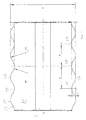
- FIG. 1 shows a sectional view of a conduit 22 as a cross section through the central longitudinal axis L of the conduit, wherein only a short portion of the entire conduit 22 is shown. However, this is done along its length as explained with reference to the section. If one speaks in each case of cross section, then such a cross-sectional view through the longitudinal axis L is according to FIG. 1 meant, which makes the shape of the corrugation of the conduit and its internal structure evident.
- the individual layers or tubes are not shown to scale or simplified for the drawing.
- the conduit 22 has a single inner medium tube 2, through which the medium or fluid to be transported flows when the conduit is used.
- the medium tube 2 may be made of plastic, for example made of polyethylene or metal. It can be a smooth pipe or a corrugated pipe.
- the medium tube 2 is surrounded by a thermal barrier coating 14, which is preferably formed from a polyurethane foam. It is explained below by means of FIG. 2 explains how the foam around the medium tube can be done.
- the thermal barrier coating is preferably formed from a rigid polyurethane foam having a density of 45 kg / m 3 to 80 kg / m 3 .
- the outer jacket 15 of the conduit 22 is shown in the drawing for the sake of simplicity only as a line, but is a plastic jacket of several millimeters thickness, in particular with a thickness in the range of 2 mm to 5 mm.
- the material of the outer jacket is also a plastic, preferably polyethylene, PE, for example as PE-LD with a density of 915 kg / m 3 to 935 kg / m 3 .
- PE polyethylene
- PE-LD polyethylene
- Other types of PE or other plastics can be used.
- the conduit 22 according to the invention is a corrugated conduit, both the outer shell 15 and the insulation 14 having the corrugation. These two parts of the conduit are in direct contact and the outer jacket 15 connects without interruption to the thermal insulation. This is especially with the hand of FIG. 2 reached explained type of production.
- the corrugation is shown with the troughs 25 and the wave crests 26, which in cross section of FIG. 1 can be seen.
- These two elements of the corrugated form are round shaped according to the invention, wherein both the corrugation 25 and the corrugation peak 26 seen in cross-section is circular or these elements of the corrugation are each part of a circle.
- a radius RT can be specified for the wave trough and a radius RB for the wave crest. It is also the case that the radius of the wave trough is greater than the radius of the wave crest, that is, the relationship RT> RB applies.
- the Wave crests and troughs are connected by substantially straight sections of the corrugation.
- the depth T of the corrugation ie the difference between the uppermost point of the wave peaks 26 and the lowest point of the troughs 25 is according to the invention in the range of 4.5 mm to 8 mm at an outer diameter D (measured from the wave crests) in the area from 63 mm to 202 mm. It has been found to be an advantage that with this shaping and dimensioning in the subsequently explained production method for the conduit a very homogeneous thickness of the outer jacket results, while other shapes or dimensions can lead to a varying thickness in the longitudinal direction of the corrugation. This is undesirable, since then the outer sheath must be chosen generally thicker to have even at the thinnest places still sufficient thickness, while then at the thickest points an unnecessary excess material is present.
- the corrugation depth T is carried out in the range of 4.5 mm to 5 mm.
- the corrugation depth T is preferably 4.5 mm.
- the corrugation depth T is carried out in the range of 5 mm to 8 mm.
- the corrugation depth T is 5.5 mm.
- the distance W of the lowest point of two successive wave troughs 25 which the effects of the homogeneous outer jacket and the good flexibility especially good results.
- This distance is preferably in the range of 25 mm to 50 mm.
- the distance W between two adjacent troughs is preferably in the range from 25 mm to 33 mm and in particular in the range from 25 mm to 27 mm.
- the distance W of the lowest point of two adjacent troughs in the range of greater than 33 mm to 50 mm and in particular in the range of greater 33 mm is up to 40 mm and in particular in the range of greater than 33 mm to 35 mm. It turns out that the preferred ranges give a good result for the bendability and the homogeneity of the outer jacket.
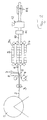
- FIG. 2 shows a preparation of the conduit 22, as in the basics EP-A 0 897 788 is known.
- a medium tube or inner tube 2 is withdrawn continuously from the storage drum 1.
- the means for stripping or conveying in the production direction are not shown, since such means are known in the art.
- the medium tube may be a plastic tube or a metal tube and it may be smooth or wavy.
- a medium tube 2 made of cross-linked polyethylene is used.
- the medium tube 2 can be guided by a pair of caliber rollers 3 whose rollers are driven.
- the caliber roller pair 3 is preferably displaceable transversely to the direction of manufacture or withdrawal direction in two mutually perpendicular directions.
- two or more medium pipes may also be present in the pipe and accordingly two or more inner pipes 2 would be fed together to the further steps.
- a plastic film 5 in particular a polyethylene film, deducted and formed around the medium tube 2 concentric with this to a tube 6 with a bonded or welded longitudinal seam.
- the plastic film 5 may also be a multilayer film.
- a foaming plastic mixture is introduced, in particular polyurethane-based or polyethylene-based, for example by means of the nozzle 7.
- the closed tube 6 is inserted into a mold 9, which is formed from a plurality of mold halves 9a and 9b, which together form "migratory shape" for the provided with the insulating layer and the film 5 and 6 medium tube.
- the film 5 thus forms the outermost layer of thermal insulation.
- the surfaces of the mold halves 9a and 9b facing the film 5 or the pipe 6 have the previously explained wave profile, into which the film 5, 6 is formed as a result of the foaming pressure.
- the blank 10 emerging from the mold 9 thus has a corrugated surface with the illustrated desired corrugation.
- the blank 10 can then pass through a known X-ray device 11, with the help of the blank 10 is continuously checked for an exact central position of the medium tube 2 or a correct position a plurality of medium pipes 2 within the insulation 14.
- the outer shell 15 of the conduit made of plastic is extruded onto the blank 10 by means of an extruder 12. It is generated in a known manner, a vacuum, which causes the concerns of the outer shell of the foamed insulation or the film 5, 6 of the blank 10.
- the outer jacket 15 applies to the corrugation of the blank 10, whereby the conduit receives the desired shape and dimensions. Due to its high temperature obtained by the extrusion, the outer sheath adheres to the plastic film 5, 6, so that the outer sheath is interrupted without interruption or directly on the thermal insulation is applied.
- the finished conduit 22 with the shaping and dimensioning according to the invention can then be removed by means of a driven trigger and wound onto a transport roller.
Landscapes
- Engineering & Computer Science (AREA)
- General Engineering & Computer Science (AREA)
- Mechanical Engineering (AREA)
- Thermal Insulation (AREA)
- Rigid Pipes And Flexible Pipes (AREA)
- Extrusion Moulding Of Plastics Or The Like (AREA)
Description
Die Erfindung betrifft ein wärmegedämmtes, gewelltes Leitungsrohr mit mindestens einem inneren Mediumsrohr aus Kunststoff oder Metall, einer das Mediumsrohr umgebenden Wärmedämmschicht aus Kunststoff und einem die Wärmedämmschicht umgebenden Aussenmantel aus Kunststoff, wobei sich die Wellung in die Wärmedämmschicht erstreckt, gemäss Oberbegriff des Anspruchs 1. Die Erfindung betrifft weiter ein Verfahren zur Herstellung eines derartigen wärmegedämmten, gewellten Leitungsrohrs.The invention relates to a thermally insulated, corrugated conduit having at least one inner plastic or metal fluid conduit, a plastic thermal barrier coating surrounding the fluid conduit and an outer shell of plastic surrounding the thermal barrier coating, the corrugation extending into the thermal barrier coating according to the preamble of claim 1 The invention further relates to a method of manufacturing such a thermally insulated corrugated conduit.
Der Erfindung liegt die Aufgabe zu Grunde ein wärmegedämmtes gewelltes Leitungsrohr mit verbesserten Eigenschaften zu schaffen.The invention is based on the object to provide a thermally insulated corrugated pipe with improved properties.
Diese Aufgabe wird bei dem eingangs genannten Leitungsrohr dadurch gelöst, dass der Rundungsradius der kreisförmigen Wellentäler bzw. Wellenberg der Rundungsradius der Wellentäler RT grösser ist als der Rundungsradius der Wellenberge RB. Dies ergibt eine besonders gute Biegbarkeit und Homogenität der Dicke des Aussenmantels.This problem is solved in the conduit mentioned above in that the radius of curvature of the circular wave troughs or wave crest of the radius of curvature of the wave troughs RT is greater than the radius of curvature of the wave crests RB. This results in a particularly good bendability and homogeneity of the thickness of the outer jacket.
Es zeigt sich, dass mit der beanspruchten Formgebung und Dimensionierung ein Aussenmantel mit einer besonders guten Gleichmässigkeit der Aussenmanteldicke erzielbar ist, so dass in den Wellentälern und den Wellenbergen weitestgehend dieselbe Materialdicke des Aussenmantels vorhanden ist. Es ergeben sich mit der Formgebung und Dimensionierung keine nachteiligen Materialansammlungen in den Wellentälern. Es zeigt sich weiter, dass damit auch bei den handelsüblichen Aussendurchmessern der Leitungsrohre im Bereich von 63 mm bis 202 mm eine deutlich verbesserte Biegbarkeit erzielt werden kann. Die Wellentäler und die Wellenberge sind im Querschnitt gesehen jeweils von einem Teil eines Kreises gebildet und somit weist das Wellental bzw. der Wellenberg jeweils eine kreisrunde Form auf, wobei die Kreisteile durch einen im Wesentlichen geraden Abschnitt verbunden sind. Die Kombination der Welltiefe im Bereich von 4,5 mm bis 8 mm und der kreisrunden Form ergibt, je nach Leitungsrohrdurchmesser, eine um 20% bis 60% erhöhte Flexibilität bei der Biegung des Leitungsrohrs im Vergleich zu einem Rohr mit glattem Mantel, was 20% bis 40% längere Liefermengen pro aufgewickelte Transporteinheit ergeben kann. Dies ergibt tiefere Logistikkosten und das Leitungsrohr ergibt mit der erhöhten Flexibilität eine vereinfachte Handhabung.It turns out that with the claimed shaping and dimensioning an outer sheath with a particularly good uniformity of the outer sheath thickness can be achieved, so that in the troughs and the wave crests largely the same material thickness of the outer sheath is present. There are no adverse material accumulations in the wave troughs with the shaping and dimensioning. It also shows that a significantly improved bendability can be achieved with the commercially available outside diameters of the pipes in the range from 63 mm to 202 mm. The wave troughs and the wave crests, viewed in cross-section, are each formed by a part of a circle, and thus the wave trough or the wave crest respectively has a circular shape, wherein the circle parts are connected by a substantially straight section are. The combination of the corrugation depth in the range of 4.5 mm to 8 mm and the circular shape gives, depending on the pipe diameter, increased flexibility by 20% to 60% in the bending of the pipe in comparison to a pipe with a smooth jacket, which is 20% Up to 40% longer delivery quantities per wound transport unit can result. This results in lower logistics costs and the conduit results in a simplified handling with the increased flexibility.
Bevorzugt ist das Leitungsrohr so ausgebildet, dass bei einem Aussendurchmesser D des Leitungsrohrs im Bereich von 63 mm bis 90 mm die Welltiefe T im Bereich von 4,5 mm bis 5 mm liegt, insbesondere, dass die Welltiefe T 4,5 mm beträgt. Weiter ist es bevorzugt, dass bei einem Aussendurchmesser D des Leitungsrohrs im Bereich von grösser als 90 mm bis 202 mm die Welltiefe T im Bereich von 5 mm bis 8 mm liegt, insbesondere, dass die Welltiefe T 5,5 mm beträgt. Es zeigt sich, dass diese Anpassung der Welltiefe an den Leitungsrohraussendurchmesser die erwähnten Vorteile besonders gut ergibt.Preferably, the conduit is formed so that at an outer diameter D of the conduit in the range of 63 mm to 90 mm, the corrugation depth T is in the range of 4.5 mm to 5 mm, in particular, that the corrugation depth T is 4.5 mm. Furthermore, it is preferred that with an outer diameter D of the conduit in the range of greater than 90 mm to 202 mm, the corrugation depth T is in the range of 5 mm to 8 mm, in particular that the corrugation depth T is 5.5 mm. It turns out that this adaptation of the corrugation depth to the pipe outside diameter gives the mentioned advantages particularly well.
Besonders bevorzugte Bereiche für die Rundungsradien für verschiedene Aussendurchmesser des Leitungsrohrs sind nachfolgend erläutert.Particularly preferred ranges for the radii of curvature for different outer diameters of the conduit are explained below.
Ferner gibt es bevorzugte Bereiche für den Abstand W zweier benachbarter Wellentäler, was ebenfalls die Biegbarkeit und die Gleichmässigkeit der Dicke des Aussenmantels positiv beeinflusst. Auch dazu werden nachfolgend bevorzugte Bereiche in Abhängigkeit vom Aussendurchmesserbereich des Leitungsrohrs angegeben.Furthermore, there are preferred ranges for the distance W of two adjacent troughs, which also positively affects the bendability and the uniformity of the thickness of the outer shell. Also for this purpose, preferred ranges are specified below as a function of the outer diameter range of the conduit.
Es zeigt sich, wie erwähnt, dass bei der Herstellung des Leitungsrohrs unter Verwendung der obigen Formgebung bzw. Parameter eine sehr homogene Verteilung des Materials des Aussenmantels entlang der Wellung ergibt, was zu einer Materialeinsparung führt. Das bevorzugte Herstellungsverfahren ist durch die Merkmale des Anspruchs 10 gegeben.It turns out, as mentioned, that in the manufacture of the conduit using the above shape or parameter results in a very homogeneous distribution of the material of the outer shell along the corrugation, resulting in a material saving. The preferred manufacturing method is given by the features of
Auch dabei werden die erwähnten bevorzugten Bereiche für die Welltiefe und/oder den Rundungsradius und/oder den Abstand der Wellenberge verwendet, wie das beim Leitungsrohr erwähnt ist, um die genannten Vorteile zu erhalten.Again, the mentioned preferred ranges for the corrugation depth and / or the radius of curvature and / or the distance of the wave crests are used, as mentioned in the conduit to obtain the advantages mentioned.
Weitere Ausgestaltungen, Vorteile und Anwendungen der Vorrichtungen und der Verfahren ergeben sich aus den abhängigen Ansprüchen und aus der folgenden Beschreibung von Ausführungsbeispielen anhand der Figuren. Dabei zeigt
-
Figur 1 einen Querschnitt durch die Mittellängsachse eines Leitungsrohrs gemäss der Erfindung; und -
Figur 2
-
FIG. 1 a cross section through the central longitudinal axis of a conduit according to the invention; and -
FIG. 2 schematically a plant for carrying out the method for producing the conduit.
Das Leitungsrohr 22 weist in diesem Ausführungsbeispiel der Erfindung ein einzelnes inneres Mediumsrohr 2 auf, durch welches bei der Verwendung des Leitungsrohrs das zu transportierende Medium bzw. Fluid fliesst. Es können auch mehrere Mediumsrohre vorhanden sein. Das Mediumsrohr 2 kann aus Kunststoff, z.B. aus Polyethylen gebildet sein oder aus Metall. Es kann ein glattes Rohr oder ein gewelltes Rohr sein. Das Mediumsrohr 2 ist von einer Wärmedämmschicht 14 umgeben, welche vorzugsweise aus einem Polyurethanschaum gebildet ist. Es wird nachfolgend anhand von
Das Leitungsrohr 22 gemäss der Erfindung ist ein gewelltes Leitungsrohr, wobei sowohl der Aussenmantel 15 als auch die Wärmedämmung 14 die Wellung aufweist. Diese beiden Teile des Leitungsrohrs liegen in direktem Kontakt und der Aussenmantel 15 schliesst unterbruchslos an die Wärmedämmung an. Dies wird besonders mit der an Hand von
Die Wellung ist mit den Wellentälern 25 und den Wellenbergen 26 dargestellt, die im Querschnitt von
Die Tiefe T der Wellung, also die Differenz zwischen der obersten Stelle der Wellenberge 26 und der untersten Stelle der Wellentäler 25 liegt gemäss der Erfindung im Bereich von 4,5 mm bis 8 mm bei einem Aussendurchmesser D (gemessen von den Wellenbergen aus) im Bereich von 63 mm bis 202 mm. Es hat sich als Vorteil gezeigt, dass mit dieser Formgebung und Dimensionierung bei der nachfolgend erläuterten Herstellungsmethode für das Leitungsrohr eine sehr homogene Dicke des Aussenmantels ergibt, während andere Formen oder Dimensionen zu einer schwankenden Dicke in Längsrichtung der Wellung führen können. Dies ist unerwünscht, da dann der Aussenmantel generell dicker gewählt werden muss, um auch an den dünnsten Stellen noch genügend Dicke aufzuweisen, während dann an den dicksten Stellen ein unnötiger Materialüberschuss vorhanden ist. Mit der erfindungsgemässen Wellformgebung und Tiefe der Wellung wird also als positiver Effekt ein Aussenmantel ermöglicht, der eine gleichmässigere Dicke aufweist und damit auch eine Materialersparnis beim Aussenmantelmaterial. Es zeig sich weiter, dass diese Merkmale, die die gleichmässige Dicke des Aussenmantels bewirken, auch eine verbesserte Biegbarkeit des Leitungsrohrs 22 ergeben.The depth T of the corrugation, ie the difference between the uppermost point of the
Bevorzugt wird bei einem Aussendurchmesser D des Leitungsrohrs 22 im Bereich von 63 mm bis 90 mm die Welltiefe T im Bereich von 4,5 mm bis 5 mm ausgeführt. Bevorzugt liegt die Welltiefe T bei 4,5 mm.Preferably, with an outer diameter D of the
Bevorzugt wird bei einem Aussendurchmesser D des Leitungsrohrs 22 im Bereich von grösser als 90 mm bis 202 mm die Welltiefe T im Bereich von 5 mm bis 8 mm ausgeführt. Bevorzugt liegt die Welltiefe T bei 5,5 mm.Preferably, with an outer diameter D of the
Ferner gibt es einen bevorzugten Bereich für den Abstand W der tiefsten Stelle zweier aufeinanderfolgender Wellentäler 25, welcher die Wirkungen des homogenen Aussenmantels und der guten Biegbarkeit besonders gut ergibt. Dieser Abstand liegt bevorzugt im Bereich von 25 mm bis 50 mm.Furthermore, there is a preferred range for the distance W of the lowest point of two
Bevorzugt liegt bei einem Aussendurchmesser D des Leitungsrohrs im Bereich von 63 mm bis 90 mm der Abstand W zweier benachbarter Wellentäler im Bereich von 25 mm bis 33 mm und insbesondere im Bereich von 25 mm bis 27 mm.In the case of an outer diameter D of the conduit in the range of 63 mm to 90 mm, the distance W between two adjacent troughs is preferably in the range from 25 mm to 33 mm and in particular in the range from 25 mm to 27 mm.
Weiter ist es bevorzugt, dass bei einem Aussendurchmesser D des Leitungsrohrs im Bereich von grösser als 90 mm bis 202 mm der Abstand W der tiefsten Stelle zweier benachbarter Wellentäler im Bereich von grösser als 33 mm bis 50 mm liegt und insbesondere im Bereich von grösser 33 mm bis 40 mm liegt und insbesondere im Bereich von grösser als 33 mm bis 35 mm liegt. Es zeigt sich, dass die bevorzugten Bereiche ein gutes Resultat für die Biegbarkeit und die Homogenität des Aussenmantels ergeben.Further, it is preferable that with an outer diameter D of the conduit in the range of greater than 90 mm to 202 mm, the distance W of the lowest point of two adjacent troughs in the range of greater than 33 mm to 50 mm and in particular in the range of greater 33 mm is up to 40 mm and in particular in the range of greater than 33 mm to 35 mm. It turns out that the preferred ranges give a good result for the bendability and the homogeneity of the outer jacket.
Von einer Vorratsspule 4 wird eine Kunststofffolie 5, insbesondere eine Polyethylenfolie, abgezogen und um das Mediumsrohr 2 konzentrisch zu diesem zu einem Rohr 6 mit einer verklebten oder verschweissten Längsnaht geformt. Die Kunststofffolie 5 kann auch eine Mehrschichtfolie sein. In das offene Rohr 6 wird ein aufschäumendes Kunststoffgemisch eingebracht, insbesondere auf Polyurethanbasis oder auf Polyethylenbasis, z.B. mittels der Düse 7. Das geschlossene Rohr 6 wird in ein Formwerkzeug 9 eingeführt, welches aus einer Vielzahl von Formhälften 9a und 9b gebildet ist, die gemeinsam eine "wandernde Form" für das mit der Isolierschicht und der Folie 5 bzw. 6 versehene Mediumsrohr bilden. Die Folie 5 bildet somit die äusserste Schicht der Wärmedämmung.From a supply reel 4, a plastic film 5, in particular a polyethylene film, deducted and formed around the
Die der Folie 5 bzw. dem Rohr 6 zugewandten Oberflächen der Formhälften 9a und 9b weisen das vorgängig erläuterte Wellenprofil auf, in welches die Folie 5, 6 infolge des Schäumdruckes eingeformt wird. Der aus dem Formwerkzeug 9 austretende Rohling 10 weist somit eine gewellte Oberfläche mit der erläuterten gewünschten Wellung auf.The surfaces of the
Der Rohling 10 kann danach eine bekannte Röntgenstrahleinrichtung 11 durchlaufen, mit deren Hilfe der Rohling 10 kontinuierlich auf eine exakt zentrische Lage des Mediumsrohrs 2 oder eine korrekte Lage mehreren Mediumsrohre 2 innerhalb der Wärmedämmung 14 überprüft wird.The blank 10 can then pass through a known
Im nächsten Herstellungsschritt wird auf den Rohling 10 mittels eines Extruders 12 der Aussenmantel 15 des Leitungsrohrs aus Kunststoff aufextrudiert. Es wird dabei auf bekannte Weise ein Vakuum erzeugt, welches das Anliegen des Aussenmantels an der geschäumten Wärmedämmung bzw. der Folie 5, 6 des Rohlings 10 bewirkt. Der Aussenmantel 15 legt sich an die Wellung des Rohlings 10 an, womit das Leitungsrohr die gewünschte Formgebung und Dimensionierung erhält. Der Aussenmantel verklebt dabei aufgrund seiner durch die Extrusion erhaltenen hohen Temperatur mit der Kunststofffolie 5, 6, so dass der Aussenmantel unterbrechungslos bzw. direkt an der Wärmedämmung anliegt. Das fertige Leitungsrohr 22 mit der Formgebung und Dimensionierung gemäss der Erfindung kann dann mittels eines angetriebenen Abzugs abgezogen und auf eine Transportrolle aufgewickelt werden.In the next production step, the
Claims (15)
- Thermally-insulated, corrugated conduit (22) comprising at least one inner service pipe (2) made from plastic or metal, wherein a thermal-insulating layer (14) made of plastic surrounds the service pipe (2) and an outer housing (15) made of plastic surrounds the thermal-insulating layer (14), wherein the corrugation (25, 26) of the conduit (22) extends into the thermal insulation layer (14), wherein the troughs (25) and peaks (26) of the corrugation have a round cross-sectional shape, wherein with an outer diameter of the conduit in the range of 63 mm to 202 mm, the corrugation depth T is in the range of 4.5 mm to 8 mm, wherein the round, cross-sectional form of the troughs (25) and peaks (26) in each case is part of a circle, wherein the circle portions are connected by substantially straight sections of the corrugation, characterized in that the radius of curvature RT of the troughs (25) is greater than the radius of curvature RB of the peaks (26).
- Conduit according to claim 1, characterized in that with an outer diameter D of the conduit (22) in the range of 63 mm to 90 mm, the corrugation depth T is in the range of 4.5 mm to 5 mm, in particular that the corrugation depth T is 4.5 mm.
- Conduit according to claim 1, characterized in that with an outer diameter D of the conduit (22) in the range of 90 mm to 202 mm, the corrugation depth T is in the range of 5 mm to 8 mm, in particular the corrugation depth T is 5.5 mm.
- Conduit according to claim 1, characterized in that with an outer diameter D of the conduit (22) in the range of 63 mm to 90 mm, the radius RT of the troughs (25) is in the range of greater than 10 mm to 11 mm, and the radius RB of the peaks is in the range of greater than 9 mm to 10 mm.
- Conduit according to claim 1, characterized in that with an outer diameter D of the conduit (22) in the range of greater than 90 mm up to 202 mm, the radius RT of the troughs (25) is in the range of greater than 15 mm up to 18 mm, and the radius RB of the peaks (26) is in the range of greater than 13 mm up to 15 mm.
- Conduit according to any one of claims 1 to 5, characterized in that the distance W of the lowest point of two adjacent troughs (25) is in the range of 25 mm to 50 mm.
- Conduit according to claim 6, characterized in that with an outer diameter D of the conduit (22) in the range of 63 mm to 90 mm, the distance W of two adjacent troughs (25) is in the range of 25 mm to 33 mm and in particular is in the range of 25 mm to 27 mm.
- Conduit according to claim 6, characterized in that with an outer diameter D of the conduit (22) in the range of greater than 90 mm up to 202 mm, the distance W of two adjacent troughs (25) is in the range of greater than 33 mm up to 50 mm and in particular is in the range of greater than 33 mm up to 40 mm and in particular is in the range of greater than 33 mm up to 35 mm.
- Conduit according to any one of claims 1 to 8, characterized in that the thermal insulation layer (14) is formed from a rigid polyurethane foam having a density of 45 kg/m3 to 80 kg/m3.
- Method for producing a thermally-insulated, corrugated conduit (22) according to any one of claims 1 - 9, comprising at least an inner service pipe (2), a corrugated outer housing (15) made of plastic arranged at a distance therefrom and a thermal insulation (14) made from foamed plastic filling out the space between service pipe (2) and outer housing, wherein the service pipe (2) is first foam-covered with the thermal insulation (14) and the thermal insulation is formed during this step, whereupon the outer housing (15) is extruded on the blank (10) formed by the foam-covered service pipe and wherein in the forming of the thermal insulation the troughs (25) and peaks (26) of the corrugation seen in cross-section are produced with round cross-sectional shape, wherein with an outer diameter of the service pipe of 63 mm to 202 mm, the corrugation depth T is produced in the range of 4.5 mm to 8 mm, wherein the round cross-sectional form of the troughs (25) and peaks (26) in each case is produced as part of a circle, characterized in that the radius of curvature RT of the troughs (25) is greater than the radius of curvature RB of the peaks (26).
- Method according to claim 10, characterized in that with an outer diameter D of the conduit (22) in the range of 63 mm to 90 mm, the radius RT of the troughs (25) is produced in the range of greater than 10 mm up to 11 mm, and the radius RB of the peaks RB is produced in the range of greater than 9 mm up to 10 mm.
- Method according to claim 10, characterized in that with an outer diameter D of the conduit (22) in the range of greater than 90 mm up to 202 mm, the radius RT of the troughs (25) is produced in the range of greater than 15 mm up to 18 mm, and the radius RB of the peaks (26) is produced in the range of greater than 13 mm up to 15 mm.
- Method according to any one of claims 10 to 12, characterized in that the distance W of the lowest point of two adjacent troughs (25) is produced in the range of 25 mm to 50 mm.
- Method according to claim 13, characterized in that with an outer diameter D of the conduit (22) in the range of 63 mm to 90 mm, the distance W of two adjacent troughs (25) is produced lying down in the range of 25 mm to 33 mm and in particular is produced lying down in the range of 25 mm to 27 mm.
- Method according to claim 13, characterized in that with an outer diameter D of the conduit (22) in the range of greater than 90 mm up to 202 mm, the distance W of two adjacent troughs (25) is produced in the range of greater than 33 mm up to 50 mm, lying down, and in particular is produced in the range of greater than 33 mm up to 40 mm, and in particular is produced in the range of greater than 33 mm up to 35 mm.
Priority Applications (3)
| Application Number | Priority Date | Filing Date | Title |
|---|---|---|---|
| RS20161115A RS55540B1 (en) | 2013-03-06 | 2014-02-26 | Thermally insulated corrugated conduit |
| SI201430146A SI2964996T1 (en) | 2013-03-06 | 2014-02-26 | Thermally insulated corrugated conduit |
| PL14708188T PL2964996T3 (en) | 2013-03-06 | 2014-02-26 | Thermally insulated corrugated conduit |
Applications Claiming Priority (2)
| Application Number | Priority Date | Filing Date | Title |
|---|---|---|---|
| CH00551/13A CH707764A2 (en) | 2013-03-06 | 2013-03-06 | Thermally insulated corrugated pipe. |
| PCT/CH2014/000025 WO2014134745A1 (en) | 2013-03-06 | 2014-02-26 | Thermally insulated corrugated conduit |
Publications (2)
| Publication Number | Publication Date |
|---|---|
| EP2964996A1 EP2964996A1 (en) | 2016-01-13 |
| EP2964996B1 true EP2964996B1 (en) | 2016-11-09 |
Family
ID=50235849
Family Applications (1)
| Application Number | Title | Priority Date | Filing Date |
|---|---|---|---|
| EP14708188.9A Active EP2964996B1 (en) | 2013-03-06 | 2014-02-26 | Thermally insulated corrugated conduit |
Country Status (15)
| Country | Link |
|---|---|
| US (1) | US10220551B2 (en) |
| EP (1) | EP2964996B1 (en) |
| KR (1) | KR102159850B1 (en) |
| CN (1) | CN105209813B (en) |
| CH (1) | CH707764A2 (en) |
| DK (1) | DK2964996T3 (en) |
| ES (1) | ES2605529T3 (en) |
| HU (1) | HUE033088T2 (en) |
| LT (1) | LT2964996T (en) |
| PL (1) | PL2964996T3 (en) |
| RS (1) | RS55540B1 (en) |
| RU (1) | RU2659650C2 (en) |
| SI (1) | SI2964996T1 (en) |
| UA (1) | UA117747C2 (en) |
| WO (1) | WO2014134745A1 (en) |
Families Citing this family (4)
| Publication number | Priority date | Publication date | Assignee | Title |
|---|---|---|---|---|
| IT201900020781A1 (en) * | 2019-11-11 | 2021-05-11 | Ecotech S R L | Thermo-insulated tube |
| EP3871873A1 (en) * | 2020-02-26 | 2021-09-01 | Brugg Rohr AG Holding | Thermally insulated pipe |
| CN112458935B (en) * | 2020-11-17 | 2022-01-07 | 河北力能建设工程有限公司 | External circular tube reinforcing structure of corrugated pipe |
| KR102609188B1 (en) * | 2023-05-08 | 2023-12-05 | 아시아티앤씨 주식회사 | Insulation jacket |
Citations (8)
| Publication number | Priority date | Publication date | Assignee | Title |
|---|---|---|---|---|
| DE2127646A1 (en) * | 1971-06-03 | 1973-01-04 | Fraenk Isolierrohr & Metall | PLASTIC PIPE WITH CORRUGATED WALL |
| DE3635515A1 (en) | 1986-10-18 | 1988-04-28 | Kabelmetal Electro Gmbh | Heat-insulated line pipe |
| EP0892207A2 (en) | 1997-07-16 | 1999-01-20 | BRUGG Rohrsysteme GmbH | Thermally insulated pipe |
| JP2002005348A (en) | 2000-06-22 | 2002-01-09 | Fujikura Ltd | Corrugated conduit tube |
| US20080245434A1 (en) | 2005-03-28 | 2008-10-09 | Motoshige Hibino | Composite Hose with a Corrugated Metal Tube and Method for Making the Same |
| CN101761708A (en) | 2008-11-06 | 2010-06-30 | 浙江三花股份有限公司 | Corrugated pipe and electronic expansion valve using the same |
| WO2010085906A1 (en) | 2009-01-29 | 2010-08-05 | Brugg Rohr Ag Holding | Method for producing a thermally insulated conduit pipe |
| CN202674603U (en) | 2012-06-13 | 2013-01-16 | 珠海格力电器股份有限公司 | Corrugated pipe and drain pipe |
Family Cites Families (16)
| Publication number | Priority date | Publication date | Assignee | Title |
|---|---|---|---|---|
| DE2104294A1 (en) | 1971-01-29 | 1972-08-03 | Fraenk Isolierrohr & Metall | |
| CH673694A5 (en) | 1986-08-21 | 1990-03-30 | Kabelmetal Electro Gmbh | |
| US5492151A (en) * | 1993-09-10 | 1996-02-20 | Dayco Products, Inc. | Vacuum cleaner hose and method and apparatus for making the same |
| FI100130B (en) * | 1995-12-12 | 1997-09-30 | Uponor Innovation Ab | Multilayer plastic pipe |
| DE19629678A1 (en) | 1996-07-23 | 1998-01-29 | Brugg Rohrsysteme Gmbh | Corrugated pipe with double walls enclosing foam insulation |
| US6279614B1 (en) * | 1997-03-29 | 2001-08-28 | Hewing Gmbh | Multi-layer plastic tube |
| US6056018A (en) * | 1997-10-29 | 2000-05-02 | E.I. Du Pont De Nemours And Company | Variable stiffness bellows |
| DE10021523C2 (en) | 2000-05-03 | 2003-05-28 | Rehau Ag & Co | pipe |
| FR2835306B1 (en) * | 2002-01-31 | 2004-05-21 | Nobel Plastiques | PIPE FOR TRANSPORTING AUTOMOTIVE FLUIDS, COMPRISING A SMOOTH INTERIOR TUBE AND AN OUTER RING TUBE |
| US6935378B2 (en) * | 2003-06-23 | 2005-08-30 | Tokai Rubber Industries, Ltd. | Vibration absorbing hose |
| DE20315754U1 (en) | 2003-10-09 | 2003-12-11 | Rehau Ag + Co. | Central heating pipe has insulating sleeve bound to it, to which corrugated outer sleeve is bound, corrugations having depth at least one fortieth of outer diameter of outer sleeve |
| JP4922785B2 (en) * | 2006-03-24 | 2012-04-25 | 東海ゴム工業株式会社 | Fuel transport hose |
| DE102006014235A1 (en) * | 2006-03-28 | 2007-10-04 | Brugg Rohr Ag, Holding | Sheath for heat-insulated pipes |
| DE202006009337U1 (en) * | 2006-06-14 | 2006-08-17 | Brugg Rohr Ag, Holding | Heat-insulated pipe used in a heating system and in drinking water and effluent lines comprises an inner pipe, a heat insulating layer surrounding the inner pipe, a film surrounding the heat insulating layer and a corrugated outer pipe |
| RU2437025C2 (en) * | 2009-12-17 | 2011-12-20 | Сергей Владимирович Кассиров | Flexible heat insulated pipe |
| CA2809480A1 (en) * | 2010-09-03 | 2012-03-08 | Aerazur S.A. | Thermoplastic hoses for airborne vehicles |
-
2013
- 2013-03-06 CH CH00551/13A patent/CH707764A2/en unknown
-
2014
- 2014-02-26 SI SI201430146A patent/SI2964996T1/en unknown
- 2014-02-26 RS RS20161115A patent/RS55540B1/en unknown
- 2014-02-26 ES ES14708188.9T patent/ES2605529T3/en active Active
- 2014-02-26 KR KR1020157027054A patent/KR102159850B1/en active IP Right Grant
- 2014-02-26 WO PCT/CH2014/000025 patent/WO2014134745A1/en active Application Filing
- 2014-02-26 LT LTEP14708188.9T patent/LT2964996T/en unknown
- 2014-02-26 RU RU2015142385A patent/RU2659650C2/en active
- 2014-02-26 EP EP14708188.9A patent/EP2964996B1/en active Active
- 2014-02-26 HU HUE14708188A patent/HUE033088T2/en unknown
- 2014-02-26 UA UAA201509591A patent/UA117747C2/en unknown
- 2014-02-26 CN CN201480021086.4A patent/CN105209813B/en active Active
- 2014-02-26 US US14/772,808 patent/US10220551B2/en active Active
- 2014-02-26 DK DK14708188.9T patent/DK2964996T3/en active
- 2014-02-26 PL PL14708188T patent/PL2964996T3/en unknown
Patent Citations (8)
| Publication number | Priority date | Publication date | Assignee | Title |
|---|---|---|---|---|
| DE2127646A1 (en) * | 1971-06-03 | 1973-01-04 | Fraenk Isolierrohr & Metall | PLASTIC PIPE WITH CORRUGATED WALL |
| DE3635515A1 (en) | 1986-10-18 | 1988-04-28 | Kabelmetal Electro Gmbh | Heat-insulated line pipe |
| EP0892207A2 (en) | 1997-07-16 | 1999-01-20 | BRUGG Rohrsysteme GmbH | Thermally insulated pipe |
| JP2002005348A (en) | 2000-06-22 | 2002-01-09 | Fujikura Ltd | Corrugated conduit tube |
| US20080245434A1 (en) | 2005-03-28 | 2008-10-09 | Motoshige Hibino | Composite Hose with a Corrugated Metal Tube and Method for Making the Same |
| CN101761708A (en) | 2008-11-06 | 2010-06-30 | 浙江三花股份有限公司 | Corrugated pipe and electronic expansion valve using the same |
| WO2010085906A1 (en) | 2009-01-29 | 2010-08-05 | Brugg Rohr Ag Holding | Method for producing a thermally insulated conduit pipe |
| CN202674603U (en) | 2012-06-13 | 2013-01-16 | 珠海格力电器股份有限公司 | Corrugated pipe and drain pipe |
Also Published As
| Publication number | Publication date |
|---|---|
| RU2659650C2 (en) | 2018-07-03 |
| US20160018047A1 (en) | 2016-01-21 |
| KR102159850B1 (en) | 2020-09-24 |
| DK2964996T3 (en) | 2017-02-13 |
| CN105209813B (en) | 2017-05-17 |
| ES2605529T3 (en) | 2017-03-14 |
| WO2014134745A1 (en) | 2014-09-12 |
| EP2964996A1 (en) | 2016-01-13 |
| HUE033088T2 (en) | 2017-11-28 |
| UA117747C2 (en) | 2018-09-25 |
| CH707764A2 (en) | 2014-09-15 |
| US10220551B2 (en) | 2019-03-05 |
| PL2964996T3 (en) | 2017-07-31 |
| KR20150125992A (en) | 2015-11-10 |
| RS55540B1 (en) | 2017-05-31 |
| SI2964996T1 (en) | 2017-03-31 |
| CN105209813A (en) | 2015-12-30 |
| LT2964996T (en) | 2017-02-10 |
| RU2015142385A (en) | 2017-04-10 |
Similar Documents
| Publication | Publication Date | Title |
|---|---|---|
| EP0897788B1 (en) | Method of manufacturing heat insulated pipe | |
| DE69831870T2 (en) | COAXIAL CABLE AND ITS MANUFACTURING PROCESS | |
| DE2836957C2 (en) | ||
| EP2213440A1 (en) | Method for producing a heat-insulated conduit pipe | |
| EP2964996B1 (en) | Thermally insulated corrugated conduit | |
| EP3112124B1 (en) | Method for coating a pipe | |
| EP2060843B1 (en) | Heat insulated pipe and method of its manufacturing | |
| EP3758910B1 (en) | Method and device for producing a heat-insulated conduit pipe | |
| DE2617140A1 (en) | DEVICE FOR THE MANUFACTURING OF PIPES FROM STRAPS Wound In The Shape Of A SCREW | |
| WO2016127267A1 (en) | Conduit comprising thermal insulation | |
| EP2284428A1 (en) | Conduit pipe and method for its production | |
| EP1640652B1 (en) | thermically insulated flexible pipe, procedure and device to manufacture said pipe | |
| AT398053B (en) | METHOD AND PIPE CONNECTOR FOR THE CONTINUOUS PRODUCTION OF LAMINATED, THERMALLY INSULATED PIPES | |
| CH622738A5 (en) | Process for producing a heat- and sound-insulated conduit pipe | |
| DE1113970B (en) | Process for the production of a cavity-insulated electrical line | |
| DE3208724C2 (en) | ||
| WO2021180842A1 (en) | Thermoplastic hose, and a device and a method for producing such a hose | |
| EP2981372B1 (en) | Method for producing a formed wire body and formed wire body | |
| DE20214563U1 (en) | Hydraulic line and extruded composite profile for use in such a hydraulic line | |
| DE102019111083B4 (en) | Protective tape, wrapped cable bundle and method | |
| DE9203386U1 (en) | Electrical power cable, device for processing the outer insulating layer of an electrical power cable made of thermoplastic material and device for coating the electrically conductive core of a power cable | |
| DE10243714B3 (en) | Hydraulic duct of pref. aluminum/alloy esp. for motor vehicles etc. consists of individual profiled tubes connected via tear-off strip, with wall thickness selected dependent upon hydraulic pressures | |
| DE3618810A1 (en) | METHOD FOR PRODUCING REINFORCED HOLLOW PROFILES AND DEVICE FOR CARRYING OUT THIS METHOD | |
| EP4134581A1 (en) | Thermally insulated, flexible conduit and method of manufacturing such a conduit | |
| DE3616774A1 (en) | HEAT-INSULATED PIPE |
Legal Events
| Date | Code | Title | Description |
|---|---|---|---|
| PUAI | Public reference made under article 153(3) epc to a published international application that has entered the european phase |
Free format text: ORIGINAL CODE: 0009012 |
|
| 17P | Request for examination filed |
Effective date: 20150928 |
|
| AK | Designated contracting states |
Kind code of ref document: A1 Designated state(s): AL AT BE BG CH CY CZ DE DK EE ES FI FR GB GR HR HU IE IS IT LI LT LU LV MC MK MT NL NO PL PT RO RS SE SI SK SM TR |
|
| AX | Request for extension of the european patent |
Extension state: BA ME |
|
| TPAC | Observations filed by third parties |
Free format text: ORIGINAL CODE: EPIDOSNTIPA |
|
| DAX | Request for extension of the european patent (deleted) | ||
| GRAP | Despatch of communication of intention to grant a patent |
Free format text: ORIGINAL CODE: EPIDOSNIGR1 |
|
| RIC1 | Information provided on ipc code assigned before grant |
Ipc: F16L 59/14 20060101ALI20160720BHEP Ipc: B29C 44/56 20060101ALI20160720BHEP Ipc: B29C 44/32 20060101ALI20160720BHEP Ipc: B29L 23/00 20060101ALN20160720BHEP Ipc: B29K 75/00 20060101ALN20160720BHEP Ipc: B29C 44/30 20060101ALI20160720BHEP Ipc: F16L 59/153 20060101AFI20160720BHEP |
|
| INTG | Intention to grant announced |
Effective date: 20160817 |
|
| RIN1 | Information on inventor provided before grant (corrected) |
Inventor name: OESCHGER, ALFRED Inventor name: RUDI, ROBERTO |
|
| GRAS | Grant fee paid |
Free format text: ORIGINAL CODE: EPIDOSNIGR3 |
|
| GRAA | (expected) grant |
Free format text: ORIGINAL CODE: 0009210 |
|
| STAA | Information on the status of an ep patent application or granted ep patent |
Free format text: STATUS: THE PATENT HAS BEEN GRANTED |
|
| AK | Designated contracting states |
Kind code of ref document: B1 Designated state(s): AL AT BE BG CH CY CZ DE DK EE ES FI FR GB GR HR HU IE IS IT LI LT LU LV MC MK MT NL NO PL PT RO RS SE SI SK SM TR |
|
| REG | Reference to a national code |
Ref country code: GB Ref legal event code: FG4D Free format text: NOT ENGLISH |
|
| REG | Reference to a national code |
Ref country code: AT Ref legal event code: REF Ref document number: 844274 Country of ref document: AT Kind code of ref document: T Effective date: 20161115 Ref country code: CH Ref legal event code: EP |
|
| REG | Reference to a national code |
Ref country code: IE Ref legal event code: FG4D Free format text: LANGUAGE OF EP DOCUMENT: GERMAN |
|
| REG | Reference to a national code |
Ref country code: DE Ref legal event code: R096 Ref document number: 502014001926 Country of ref document: DE |
|
| REG | Reference to a national code |
Ref country code: RO Ref legal event code: EPE |
|
| REG | Reference to a national code |
Ref country code: NL Ref legal event code: FP |
|
| REG | Reference to a national code |
Ref country code: DK Ref legal event code: T3 Effective date: 20170209 |
|
| REG | Reference to a national code |
Ref country code: FR Ref legal event code: PLFP Year of fee payment: 4 |
|
| REG | Reference to a national code |
Ref country code: SE Ref legal event code: TRGR |
|
| REG | Reference to a national code |
Ref country code: ES Ref legal event code: FG2A Ref document number: 2605529 Country of ref document: ES Kind code of ref document: T3 Effective date: 20170314 |
|
| REG | Reference to a national code |
Ref country code: NO Ref legal event code: T2 Effective date: 20161109 |
|
| REG | Reference to a national code |
Ref country code: EE Ref legal event code: FG4A Ref document number: E013401 Country of ref document: EE Effective date: 20170209 |
|
| PG25 | Lapsed in a contracting state [announced via postgrant information from national office to epo] |
Ref country code: GR Free format text: LAPSE BECAUSE OF FAILURE TO SUBMIT A TRANSLATION OF THE DESCRIPTION OR TO PAY THE FEE WITHIN THE PRESCRIBED TIME-LIMIT Effective date: 20170210 |
|
| PG25 | Lapsed in a contracting state [announced via postgrant information from national office to epo] |
Ref country code: PT Free format text: LAPSE BECAUSE OF FAILURE TO SUBMIT A TRANSLATION OF THE DESCRIPTION OR TO PAY THE FEE WITHIN THE PRESCRIBED TIME-LIMIT Effective date: 20170309 Ref country code: HR Free format text: LAPSE BECAUSE OF FAILURE TO SUBMIT A TRANSLATION OF THE DESCRIPTION OR TO PAY THE FEE WITHIN THE PRESCRIBED TIME-LIMIT Effective date: 20161109 |
|
| REG | Reference to a national code |
Ref country code: DE Ref legal event code: R026 Ref document number: 502014001926 Country of ref document: DE |
|
| PLBI | Opposition filed |
Free format text: ORIGINAL CODE: 0009260 |
|
| PG25 | Lapsed in a contracting state [announced via postgrant information from national office to epo] |
Ref country code: SM Free format text: LAPSE BECAUSE OF FAILURE TO SUBMIT A TRANSLATION OF THE DESCRIPTION OR TO PAY THE FEE WITHIN THE PRESCRIBED TIME-LIMIT Effective date: 20161109 |
|
| PLAX | Notice of opposition and request to file observation + time limit sent |
Free format text: ORIGINAL CODE: EPIDOSNOBS2 |
|
| 26 | Opposition filed |
Opponent name: ISOPLUS FERNWAERMETECHNIK GESELLSCHAFT M.B.H. Effective date: 20170807 |
|
| PG25 | Lapsed in a contracting state [announced via postgrant information from national office to epo] |
Ref country code: MC Free format text: LAPSE BECAUSE OF FAILURE TO SUBMIT A TRANSLATION OF THE DESCRIPTION OR TO PAY THE FEE WITHIN THE PRESCRIBED TIME-LIMIT Effective date: 20161109 |
|
| REG | Reference to a national code |
Ref country code: HU Ref legal event code: AG4A Ref document number: E033088 Country of ref document: HU |
|
| PG25 | Lapsed in a contracting state [announced via postgrant information from national office to epo] |
Ref country code: LU Free format text: LAPSE BECAUSE OF NON-PAYMENT OF DUE FEES Effective date: 20170226 |
|
| PLBB | Reply of patent proprietor to notice(s) of opposition received |
Free format text: ORIGINAL CODE: EPIDOSNOBS3 |
|
| REG | Reference to a national code |
Ref country code: FR Ref legal event code: PLFP Year of fee payment: 5 |
|
| PLAY | Examination report in opposition despatched + time limit |
Free format text: ORIGINAL CODE: EPIDOSNORE2 |
|
| PLAH | Information related to despatch of examination report in opposition + time limit modified |
Free format text: ORIGINAL CODE: EPIDOSCORE2 |
|
| PG25 | Lapsed in a contracting state [announced via postgrant information from national office to epo] |
Ref country code: MT Free format text: LAPSE BECAUSE OF FAILURE TO SUBMIT A TRANSLATION OF THE DESCRIPTION OR TO PAY THE FEE WITHIN THE PRESCRIBED TIME-LIMIT Effective date: 20161109 |
|
| PLBC | Reply to examination report in opposition received |
Free format text: ORIGINAL CODE: EPIDOSNORE3 |
|
| PG25 | Lapsed in a contracting state [announced via postgrant information from national office to epo] |
Ref country code: CY Free format text: LAPSE BECAUSE OF FAILURE TO SUBMIT A TRANSLATION OF THE DESCRIPTION OR TO PAY THE FEE WITHIN THE PRESCRIBED TIME-LIMIT Effective date: 20161109 |
|
| PG25 | Lapsed in a contracting state [announced via postgrant information from national office to epo] |
Ref country code: MK Free format text: LAPSE BECAUSE OF FAILURE TO SUBMIT A TRANSLATION OF THE DESCRIPTION OR TO PAY THE FEE WITHIN THE PRESCRIBED TIME-LIMIT Effective date: 20161109 |
|
| PGFP | Annual fee paid to national office [announced via postgrant information from national office to epo] |
Ref country code: ES Payment date: 20200309 Year of fee payment: 7 Ref country code: LT Payment date: 20200122 Year of fee payment: 7 Ref country code: LV Payment date: 20200220 Year of fee payment: 7 Ref country code: RO Payment date: 20200128 Year of fee payment: 7 Ref country code: HU Payment date: 20200210 Year of fee payment: 7 Ref country code: EE Payment date: 20200225 Year of fee payment: 7 Ref country code: BG Payment date: 20200228 Year of fee payment: 7 |
|
| PG25 | Lapsed in a contracting state [announced via postgrant information from national office to epo] |
Ref country code: AL Free format text: LAPSE BECAUSE OF FAILURE TO SUBMIT A TRANSLATION OF THE DESCRIPTION OR TO PAY THE FEE WITHIN THE PRESCRIBED TIME-LIMIT Effective date: 20161109 |
|
| TPAC | Observations filed by third parties |
Free format text: ORIGINAL CODE: EPIDOSNTIPA |
|
| TPAC | Observations filed by third parties |
Free format text: ORIGINAL CODE: EPIDOSNTIPA |
|
| PGFP | Annual fee paid to national office [announced via postgrant information from national office to epo] |
Ref country code: IE Payment date: 20210225 Year of fee payment: 8 |
|
| PGFP | Annual fee paid to national office [announced via postgrant information from national office to epo] |
Ref country code: RS Payment date: 20210121 Year of fee payment: 8 Ref country code: TR Payment date: 20210223 Year of fee payment: 8 Ref country code: SI Payment date: 20210126 Year of fee payment: 8 |
|
| PGFP | Annual fee paid to national office [announced via postgrant information from national office to epo] |
Ref country code: SK Payment date: 20210125 Year of fee payment: 8 |
|
| REG | Reference to a national code |
Ref country code: EE Ref legal event code: MM4A Ref document number: E013401 Country of ref document: EE Effective date: 20210228 |
|
| REG | Reference to a national code |
Ref country code: LT Ref legal event code: MM4D Effective date: 20210226 |
|
| PG25 | Lapsed in a contracting state [announced via postgrant information from national office to epo] |
Ref country code: HU Free format text: LAPSE BECAUSE OF NON-PAYMENT OF DUE FEES Effective date: 20210227 Ref country code: BG Free format text: LAPSE BECAUSE OF NON-PAYMENT OF DUE FEES Effective date: 20210831 Ref country code: EE Free format text: LAPSE BECAUSE OF NON-PAYMENT OF DUE FEES Effective date: 20210228 |
|
| PG25 | Lapsed in a contracting state [announced via postgrant information from national office to epo] |
Ref country code: LV Free format text: LAPSE BECAUSE OF NON-PAYMENT OF DUE FEES Effective date: 20210226 Ref country code: RO Free format text: LAPSE BECAUSE OF NON-PAYMENT OF DUE FEES Effective date: 20210226 |
|
| REG | Reference to a national code |
Ref country code: DE Ref legal event code: R100 Ref document number: 502014001926 Country of ref document: DE |
|
| PG25 | Lapsed in a contracting state [announced via postgrant information from national office to epo] |
Ref country code: LT Free format text: LAPSE BECAUSE OF NON-PAYMENT OF DUE FEES Effective date: 20210226 |
|
| PLCK | Communication despatched that opposition was rejected |
Free format text: ORIGINAL CODE: EPIDOSNREJ1 |
|
| STAA | Information on the status of an ep patent application or granted ep patent |
Free format text: STATUS: THE PATENT HAS BEEN GRANTED |
|
| REG | Reference to a national code |
Ref country code: ES Ref legal event code: FD2A Effective date: 20220513 |
|
| PLBN | Opposition rejected |
Free format text: ORIGINAL CODE: 0009273 |
|
| STAA | Information on the status of an ep patent application or granted ep patent |
Free format text: STATUS: OPPOSITION REJECTED |
|
| 27O | Opposition rejected |
Effective date: 20211208 |
|
| REG | Reference to a national code |
Ref country code: SK Ref legal event code: MM4A Ref document number: E 23416 Country of ref document: SK Effective date: 20220226 |
|
| PG25 | Lapsed in a contracting state [announced via postgrant information from national office to epo] |
Ref country code: SK Free format text: LAPSE BECAUSE OF NON-PAYMENT OF DUE FEES Effective date: 20220226 |
|
| PG25 | Lapsed in a contracting state [announced via postgrant information from national office to epo] |
Ref country code: SI Free format text: LAPSE BECAUSE OF NON-PAYMENT OF DUE FEES Effective date: 20220227 Ref country code: RS Free format text: LAPSE BECAUSE OF NON-PAYMENT OF DUE FEES Effective date: 20220226 |
|
| REG | Reference to a national code |
Ref country code: SI Ref legal event code: KO00 Effective date: 20221013 |
|
| PG25 | Lapsed in a contracting state [announced via postgrant information from national office to epo] |
Ref country code: IE Free format text: LAPSE BECAUSE OF NON-PAYMENT OF DUE FEES Effective date: 20220226 |
|
| P01 | Opt-out of the competence of the unified patent court (upc) registered |
Effective date: 20230328 |
|
| PG25 | Lapsed in a contracting state [announced via postgrant information from national office to epo] |
Ref country code: ES Free format text: LAPSE BECAUSE OF NON-PAYMENT OF DUE FEES Effective date: 20210227 |
|
| PGFP | Annual fee paid to national office [announced via postgrant information from national office to epo] |
Ref country code: IS Payment date: 20240206 Year of fee payment: 11 |
|
| PGFP | Annual fee paid to national office [announced via postgrant information from national office to epo] |
Ref country code: NL Payment date: 20240222 Year of fee payment: 11 |
|
| PGFP | Annual fee paid to national office [announced via postgrant information from national office to epo] |
Ref country code: AT Payment date: 20240226 Year of fee payment: 11 |
|
| PGFP | Annual fee paid to national office [announced via postgrant information from national office to epo] |
Ref country code: FI Payment date: 20240220 Year of fee payment: 11 Ref country code: DE Payment date: 20240228 Year of fee payment: 11 Ref country code: CZ Payment date: 20240122 Year of fee payment: 11 Ref country code: GB Payment date: 20240221 Year of fee payment: 11 Ref country code: CH Payment date: 20240301 Year of fee payment: 11 |
|
| PGFP | Annual fee paid to national office [announced via postgrant information from national office to epo] |
Ref country code: SE Payment date: 20240222 Year of fee payment: 11 Ref country code: PL Payment date: 20240129 Year of fee payment: 11 Ref country code: NO Payment date: 20240220 Year of fee payment: 11 Ref country code: IT Payment date: 20240227 Year of fee payment: 11 Ref country code: FR Payment date: 20240227 Year of fee payment: 11 Ref country code: DK Payment date: 20240222 Year of fee payment: 11 Ref country code: BE Payment date: 20240222 Year of fee payment: 11 |