EP4134581A1 - Thermally insulated, flexible conduit and method of manufacturing such a conduit - Google Patents
Thermally insulated, flexible conduit and method of manufacturing such a conduit Download PDFInfo
- Publication number
- EP4134581A1 EP4134581A1 EP21190596.3A EP21190596A EP4134581A1 EP 4134581 A1 EP4134581 A1 EP 4134581A1 EP 21190596 A EP21190596 A EP 21190596A EP 4134581 A1 EP4134581 A1 EP 4134581A1
- Authority
- EP
- European Patent Office
- Prior art keywords
- pipe
- thermal insulation
- film
- casing
- medium pipe
- Prior art date
- Legal status (The legal status is an assumption and is not a legal conclusion. Google has not performed a legal analysis and makes no representation as to the accuracy of the status listed.)
- Pending
Links
- 230000009975 flexible effect Effects 0.000 title claims abstract description 26
- 238000004519 manufacturing process Methods 0.000 title claims abstract description 17
- 238000009413 insulation Methods 0.000 claims abstract description 115
- 230000001681 protective effect Effects 0.000 claims abstract description 38
- 230000002787 reinforcement Effects 0.000 claims abstract description 21
- 239000012815 thermoplastic material Substances 0.000 claims abstract description 12
- 229920003023 plastic Polymers 0.000 claims description 72
- 239000004033 plastic Substances 0.000 claims description 72
- 239000000203 mixture Substances 0.000 claims description 65
- 230000003014 reinforcing effect Effects 0.000 claims description 44
- 238000000034 method Methods 0.000 claims description 40
- 238000005187 foaming Methods 0.000 claims description 36
- 239000011888 foil Substances 0.000 claims description 33
- 239000007788 liquid Substances 0.000 claims description 33
- 239000000835 fiber Substances 0.000 claims description 29
- 229920001903 high density polyethylene Polymers 0.000 claims description 24
- 239000004700 high-density polyethylene Substances 0.000 claims description 24
- -1 polyethylene Polymers 0.000 claims description 22
- 229920001169 thermoplastic Polymers 0.000 claims description 21
- 239000002131 composite material Substances 0.000 claims description 17
- 239000006260 foam Substances 0.000 claims description 17
- 239000004416 thermosoftening plastic Substances 0.000 claims description 15
- 239000002984 plastic foam Substances 0.000 claims description 13
- 239000004952 Polyamide Substances 0.000 claims description 11
- 239000004698 Polyethylene Substances 0.000 claims description 11
- 239000004743 Polypropylene Substances 0.000 claims description 11
- 229920002647 polyamide Polymers 0.000 claims description 11
- 229920000573 polyethylene Polymers 0.000 claims description 11
- 229920000098 polyolefin Polymers 0.000 claims description 11
- 229920001155 polypropylene Polymers 0.000 claims description 11
- XLYOFNOQVPJJNP-UHFFFAOYSA-N water Substances O XLYOFNOQVPJJNP-UHFFFAOYSA-N 0.000 claims description 11
- 239000003921 oil Substances 0.000 claims description 7
- 229920002635 polyurethane Polymers 0.000 claims description 7
- 239000004814 polyurethane Substances 0.000 claims description 7
- 229920000582 polyisocyanurate Polymers 0.000 claims description 6
- 239000011495 polyisocyanurate Substances 0.000 claims description 6
- 229920000049 Carbon (fiber) Polymers 0.000 claims description 4
- 239000004760 aramid Substances 0.000 claims description 4
- 229920006231 aramid fiber Polymers 0.000 claims description 4
- 239000004917 carbon fiber Substances 0.000 claims description 4
- 239000003365 glass fiber Substances 0.000 claims description 4
- 239000010779 crude oil Substances 0.000 claims description 3
- 235000019198 oils Nutrition 0.000 claims description 3
- 238000007493 shaping process Methods 0.000 claims description 3
- 235000019476 oil-water mixture Nutrition 0.000 claims description 2
- 229920000728 polyester Polymers 0.000 claims description 2
- 238000009751 slip forming Methods 0.000 claims description 2
- 239000000126 substance Substances 0.000 claims description 2
- 229920002397 thermoplastic olefin Polymers 0.000 claims description 2
- 239000002609 medium Substances 0.000 description 102
- 239000010410 layer Substances 0.000 description 76
- 238000001816 cooling Methods 0.000 description 13
- 239000002985 plastic film Substances 0.000 description 10
- 229920006255 plastic film Polymers 0.000 description 10
- 238000010438 heat treatment Methods 0.000 description 9
- 238000001125 extrusion Methods 0.000 description 8
- 238000005470 impregnation Methods 0.000 description 6
- 238000002156 mixing Methods 0.000 description 5
- 238000000465 moulding Methods 0.000 description 5
- 239000011248 coating agent Substances 0.000 description 4
- 238000000576 coating method Methods 0.000 description 4
- 150000001875 compounds Chemical class 0.000 description 4
- 239000000498 cooling water Substances 0.000 description 4
- 239000007789 gas Substances 0.000 description 4
- 125000006850 spacer group Chemical group 0.000 description 4
- 229920005830 Polyurethane Foam Polymers 0.000 description 3
- 239000012948 isocyanate Substances 0.000 description 3
- 150000002513 isocyanates Chemical class 0.000 description 3
- 229920001684 low density polyethylene Polymers 0.000 description 3
- 239000004702 low-density polyethylene Substances 0.000 description 3
- 229920005862 polyol Polymers 0.000 description 3
- 150000003077 polyols Chemical class 0.000 description 3
- 239000011496 polyurethane foam Substances 0.000 description 3
- 239000007921 spray Substances 0.000 description 3
- 238000003860 storage Methods 0.000 description 3
- 238000004804 winding Methods 0.000 description 3
- 229920002748 Basalt fiber Polymers 0.000 description 2
- 229920002430 Fibre-reinforced plastic Polymers 0.000 description 2
- 239000000919 ceramic Substances 0.000 description 2
- 238000005253 cladding Methods 0.000 description 2
- 238000010924 continuous production Methods 0.000 description 2
- 238000011161 development Methods 0.000 description 2
- 230000018109 developmental process Effects 0.000 description 2
- 239000004744 fabric Substances 0.000 description 2
- 239000011151 fibre-reinforced plastic Substances 0.000 description 2
- 239000011810 insulating material Substances 0.000 description 2
- 239000011159 matrix material Substances 0.000 description 2
- 239000000843 powder Substances 0.000 description 2
- 239000012783 reinforcing fiber Substances 0.000 description 2
- 239000006163 transport media Substances 0.000 description 2
- 230000001070 adhesive effect Effects 0.000 description 1
- 238000010276 construction Methods 0.000 description 1
- 230000003111 delayed effect Effects 0.000 description 1
- 230000001419 dependent effect Effects 0.000 description 1
- 239000003651 drinking water Substances 0.000 description 1
- 235000020188 drinking water Nutrition 0.000 description 1
- 229920000092 linear low density polyethylene Polymers 0.000 description 1
- 239000004707 linear low-density polyethylene Substances 0.000 description 1
- 239000000463 material Substances 0.000 description 1
- 229920001228 polyisocyanate Polymers 0.000 description 1
- 239000005056 polyisocyanate Substances 0.000 description 1
- 239000011241 protective layer Substances 0.000 description 1
- 238000003303 reheating Methods 0.000 description 1
- 230000000630 rising effect Effects 0.000 description 1
- 239000002351 wastewater Substances 0.000 description 1
- 238000003466 welding Methods 0.000 description 1
- 239000002759 woven fabric Substances 0.000 description 1
Images

Classifications
-
- F—MECHANICAL ENGINEERING; LIGHTING; HEATING; WEAPONS; BLASTING
- F16—ENGINEERING ELEMENTS AND UNITS; GENERAL MEASURES FOR PRODUCING AND MAINTAINING EFFECTIVE FUNCTIONING OF MACHINES OR INSTALLATIONS; THERMAL INSULATION IN GENERAL
- F16L—PIPES; JOINTS OR FITTINGS FOR PIPES; SUPPORTS FOR PIPES, CABLES OR PROTECTIVE TUBING; MEANS FOR THERMAL INSULATION IN GENERAL
- F16L59/00—Thermal insulation in general
- F16L59/14—Arrangements for the insulation of pipes or pipe systems
- F16L59/153—Arrangements for the insulation of pipes or pipe systems for flexible pipes
-
- B—PERFORMING OPERATIONS; TRANSPORTING
- B29—WORKING OF PLASTICS; WORKING OF SUBSTANCES IN A PLASTIC STATE IN GENERAL
- B29C—SHAPING OR JOINING OF PLASTICS; SHAPING OF MATERIAL IN A PLASTIC STATE, NOT OTHERWISE PROVIDED FOR; AFTER-TREATMENT OF THE SHAPED PRODUCTS, e.g. REPAIRING
- B29C48/00—Extrusion moulding, i.e. expressing the moulding material through a die or nozzle which imparts the desired form; Apparatus therefor
- B29C48/03—Extrusion moulding, i.e. expressing the moulding material through a die or nozzle which imparts the desired form; Apparatus therefor characterised by the shape of the extruded material at extrusion
- B29C48/09—Articles with cross-sections having partially or fully enclosed cavities, e.g. pipes or channels
-
- B—PERFORMING OPERATIONS; TRANSPORTING
- B29—WORKING OF PLASTICS; WORKING OF SUBSTANCES IN A PLASTIC STATE IN GENERAL
- B29C—SHAPING OR JOINING OF PLASTICS; SHAPING OF MATERIAL IN A PLASTIC STATE, NOT OTHERWISE PROVIDED FOR; AFTER-TREATMENT OF THE SHAPED PRODUCTS, e.g. REPAIRING
- B29C48/00—Extrusion moulding, i.e. expressing the moulding material through a die or nozzle which imparts the desired form; Apparatus therefor
- B29C48/15—Extrusion moulding, i.e. expressing the moulding material through a die or nozzle which imparts the desired form; Apparatus therefor incorporating preformed parts or layers, e.g. extrusion moulding around inserts
- B29C48/151—Coating hollow articles
-
- B—PERFORMING OPERATIONS; TRANSPORTING
- B29—WORKING OF PLASTICS; WORKING OF SUBSTANCES IN A PLASTIC STATE IN GENERAL
- B29C—SHAPING OR JOINING OF PLASTICS; SHAPING OF MATERIAL IN A PLASTIC STATE, NOT OTHERWISE PROVIDED FOR; AFTER-TREATMENT OF THE SHAPED PRODUCTS, e.g. REPAIRING
- B29C48/00—Extrusion moulding, i.e. expressing the moulding material through a die or nozzle which imparts the desired form; Apparatus therefor
- B29C48/16—Articles comprising two or more components, e.g. co-extruded layers
- B29C48/18—Articles comprising two or more components, e.g. co-extruded layers the components being layers
- B29C48/21—Articles comprising two or more components, e.g. co-extruded layers the components being layers the layers being joined at their surfaces
-
- F—MECHANICAL ENGINEERING; LIGHTING; HEATING; WEAPONS; BLASTING
- F16—ENGINEERING ELEMENTS AND UNITS; GENERAL MEASURES FOR PRODUCING AND MAINTAINING EFFECTIVE FUNCTIONING OF MACHINES OR INSTALLATIONS; THERMAL INSULATION IN GENERAL
- F16L—PIPES; JOINTS OR FITTINGS FOR PIPES; SUPPORTS FOR PIPES, CABLES OR PROTECTIVE TUBING; MEANS FOR THERMAL INSULATION IN GENERAL
- F16L11/00—Hoses, i.e. flexible pipes
- F16L11/04—Hoses, i.e. flexible pipes made of rubber or flexible plastics
- F16L11/10—Hoses, i.e. flexible pipes made of rubber or flexible plastics with reinforcements not embedded in the wall
-
- F—MECHANICAL ENGINEERING; LIGHTING; HEATING; WEAPONS; BLASTING
- F16—ENGINEERING ELEMENTS AND UNITS; GENERAL MEASURES FOR PRODUCING AND MAINTAINING EFFECTIVE FUNCTIONING OF MACHINES OR INSTALLATIONS; THERMAL INSULATION IN GENERAL
- F16L—PIPES; JOINTS OR FITTINGS FOR PIPES; SUPPORTS FOR PIPES, CABLES OR PROTECTIVE TUBING; MEANS FOR THERMAL INSULATION IN GENERAL
- F16L59/00—Thermal insulation in general
- F16L59/02—Shape or form of insulating materials, with or without coverings integral with the insulating materials
- F16L59/021—Shape or form of insulating materials, with or without coverings integral with the insulating materials comprising a single piece or sleeve, e.g. split sleeve, two half sleeves
-
- F—MECHANICAL ENGINEERING; LIGHTING; HEATING; WEAPONS; BLASTING
- F16—ENGINEERING ELEMENTS AND UNITS; GENERAL MEASURES FOR PRODUCING AND MAINTAINING EFFECTIVE FUNCTIONING OF MACHINES OR INSTALLATIONS; THERMAL INSULATION IN GENERAL
- F16L—PIPES; JOINTS OR FITTINGS FOR PIPES; SUPPORTS FOR PIPES, CABLES OR PROTECTIVE TUBING; MEANS FOR THERMAL INSULATION IN GENERAL
- F16L59/00—Thermal insulation in general
- F16L59/14—Arrangements for the insulation of pipes or pipe systems
- F16L59/147—Arrangements for the insulation of pipes or pipe systems the insulation being located inwardly of the outer surface of the pipe
Definitions
- the invention relates to a thermally insulated, flexible conduit.
- the invention also relates to a method for producing a thermally insulated, flexible conduit.
- Fiber-reinforced plastic pipes are often used as flexible line pipes, which are used to transport different media such as water, oil or gas, for example in onshore or offshore production for transport on land or above the sea floor.
- Flexible pipelines are also used in district heating pipeline construction to transport media for water and heating supply systems.
- fiber-reinforced plastic pipes such as thermoplastic composite pipes ("Thermoplastic Composite Pipes", TCP)
- TCP thermoplastic Composite Pipes
- TCP thermoplastic Composite Pipes
- Thermoplastic composite pipes usually have an inner layer made of one or more layers of inner liner made of thermoplastic material. A composite layer is applied to this, for example by winding fiber-reinforced tapes.
- Such composite tubes are for example from the document WO 95/07428 A1 or WO 2017/048117 A1 known.
- heat losses can occur when a medium, particularly a warm or hot medium, is transported over long distances using thermoplastic composite pipes.
- the heat losses can lead to a change in the flowability of the transported medium or to a temperature level no longer being able to be provided for a subsequent application. In such cases, a complex and energy-intensive reheating of the medium is then necessary. I the same way it can be used when transporting cold media at high Ambient temperatures become necessary to cool the medium again, which is costly.
- the object of the invention is to structurally and/or functionally improve a line pipe as mentioned at the outset.
- the invention is based on the object of functionally improving a method for the production of a conduit mentioned at the outset.
- the object is achieved with a line pipe having the features of claim 1.
- the object is also achieved with a method for producing a line pipe having the features of claim 12.
- Advantageous designs and/or developments are the subject matter of the dependent claims.
- a duct can be a thermally insulated and/or flexible duct.
- the line pipe can comprise at least one medium pipe.
- the line pipe can include, for example, two, three, four or more medium pipes.
- the medium pipe can have an inner pipe, for example made of plastic, such as thermoplastic material.
- the carrier pipe may have a reinforcement layer arranged around the inner pipe.
- the carrier pipe may have a protective jacket arranged around the reinforcement layer.
- the line pipe and/or its medium pipe can be used and/or designed to transport different media, such as liquid or gaseous media such as water, oil or gas.
- the inner pipe of the medium pipe can serve and/or be designed to transport different media, such as liquid or gaseous media, such as water, oil, such as crude oil, or gas, such as crude gas.
- the line pipe can serve and/or be designed for use in water, oil or gas networks or water, oil or gas lines.
- the line pipe can be used and/or designed for use in onshore or offshore production or onshore or offshore transport for transporting a medium on land or above the seabed.
- the pipe can serve and/or be designed for use in local or district heating networks or local or district heating lines.
- the pipe can be used in geothermal networks or geothermal lines and/or be trained.
- the pipe can be designed, for example, to transport media for water and heating supply systems.
- the line pipe can be used and/or designed for use in drinking water or waste water lines.
- the line pipe and/or its medium pipe can be, for example, a flexible and/or coilable and/or non-metallic pipe, in particular a composite pipe.
- the composite pipe can be a thermoplastic composite pipe.
- the line pipe and/or its medium pipe can be designed to be bendable.
- the line pipe and/or its medium pipe can be designed in such a way that it can be wound into rings and/or onto drums.
- the conduit and/or its carrier pipe can be adaptable to terrain conditions.
- the conduit can have an inside diameter of about 30 to 200 mm.
- the conduit can have an outside diameter of about 76 to 355 mm.
- the terms “axial”, “radial” and “in the circumferential direction” refer to a direction of extension of the longitudinal axis and/or axis of symmetry of the conduit and/or medium pipe.
- the line pipe and/or its medium pipe can be concentric to the longitudinal axis and/or the axis of symmetry.
- “Axial” then corresponds to an extension direction of the longitudinal axis and/or axis of symmetry.
- “Radial” is then a direction perpendicular to the direction of extent of the longitudinal axis and/or axis of symmetry and intersecting with the longitudinal axis and/or axis of symmetry.
- “In the circumferential direction” then corresponds to a circular arc direction around the longitudinal axis and/or axis of symmetry.
- the medium pipe can be a fiber-reinforced, for example thermoplastic, plastic pipe.
- the medium pipe can be a multi-layer pipe.
- the medium pipe can be a composite pipe, for example a thermoplastic pipe.
- the service pipe can be a reinforced, such as fiber-reinforced, composite pipe.
- the service pipe can be a composite pipe.
- the carrier pipe can be a thermoplastic composite pipe such as Thermoplastic Composite Pipe (TCP).
- TCP The medium pipe can be arranged radially on the inside of the line pipe.
- the carrier pipe can be a base pipe or carrier pipe.
- the service pipe can be extruded or pultruded or become.
- the medium pipe can be produced by means of an extrusion process, for example a coextrusion process, or a pultrusion process.
- the medium pipe can be produced or extruded by means of an extruder or a plurality of extruders and/or a pipe head.
- the inner pipe of the carrier pipe can be an inner liner.
- the inner pipe or the inner liner can have one or more layers.
- the inner tube can be a multi-layer tube.
- the inner tube can be a base tube or carrier tube.
- the inner pipe of the medium pipe can be arranged radially on the inside of the medium pipe.
- the inner tube can be a plastic tube, such as a thermoplastic plastic tube.
- the inner pipe of the medium pipe can be made of, for example, thermoplastic plastic.
- the plastic can be or include, for example, polyolefin, polyethylene, high-density polyethylene (HDPE), polypropylene or polyamide.
- the inner tube can be extruded or pultruded.
- the inner tube can be produced by means of an extrusion process or a pultrusion process.
- the inner tube can be produced or extruded by means of an extruder and/or a tube head.
- the reinforcement layer of the carrier pipe can have at least one layer of reinforcing fibers.
- the fibers can be glass fibers and/or plastic fibers and/or carbon fibers and/or aramid fibers and/or basalt fibers and/or ceramic fibers.
- the cross-section of the fibers can be circular, rectangular, oval, elliptical, or cocoon-shaped.
- the fibers can be designed as short fibers, long fibers or endless fibers.
- the fibers can be constructed as a woven fabric or with a unidirectional fiber layer.
- the reinforcing layer of the service pipe may comprise a matrix material made from fibers impregnated with plastic.
- the plastic can be a thermoplastic material.
- the plastic can be or include, for example, polyolefin, polyethylene, high-density polyethylene (HDPE), polypropylene or polyamide.
- the matrix material can be produced, for example, by means of an impregnation process, melt application process, melt impregnation process, powder impregnation process or pultrusion process.
- the reinforcement layer of the medium pipe can be arranged in the radial direction between the inner pipe and the protective jacket of the medium pipe.
- the reinforcing layer of the carrier pipe may include at least a first layer of reinforcing tape.
- the first layer of reinforcing tape may be substantially helically wrapped around the inner tube in a first helical direction.
- the reinforcement layer may include at least a second layer of reinforcing tape.
- the second layer of reinforcing tape may be substantially helically wrapped around the inner tube and/or the first layer of reinforcing tape in a second helical direction, for example counter to the first helical direction.
- reinforcing tape There may be several, such as three, four or more layers of reinforcing tape, each of which is or will be wrapped around the inner tube in a helical direction, particularly in different helical directions.
- the multiple layers of reinforcing tape may be configured like the first and/or second layers of reinforcing tape.
- the first layer of reinforcing tape may comprise a reinforcing tape having fibers impregnated with plastic.
- the second layer of reinforcing tape may comprise a reinforcing tape having fibers impregnated with plastic.
- the plastic can be a thermoplastic material.
- the plastic can be or include, for example, polyolefin, polyethylene, high-density polyethylene (HDPE), polypropylene or polyamide.
- the fibers of the first and/or second layers of reinforcing tape may be or will be arranged and/or aligned unidirectionally.
- the first and/or second layer of reinforcing tape may comprise a plastics impregnated fibrous tape such as continuous filaments, woven or knitted fabrics.
- the plastic can be a thermoplastic material.
- the plastic can be or include, for example, polyolefin, polyethylene, high-density polyethylene (HDPE), polypropylene or polyamide.
- the fibers of the first and/or second layer of reinforcing tape can be reinforcing fibers, for example glass fibers and/or plastic fibers and/or carbon fibers and/or aramid fibers and/or basalt fibers and/or ceramic fibers.
- the cross-section of the fibers can be circular, rectangular, oval, elliptical, or cocoon-shaped be.
- the fibers can be designed as short fibers, long fibers or endless fibers.
- the fibers can be designed and/or arranged as a woven or knitted fabric or with a unidirectional fiber layer.
- the first and/or second layer of reinforcing tape may also be referred to as tape, such as fiber reinforced tape.
- the first and/or second layer of reinforcing tape can be produced, for example, by means of an impregnation process, melt application process, melt impregnation process, powder impregnation process or pultrusion process.
- the reinforcing layer can be or will be permanently connected to the inner pipe of the medium pipe.
- the reinforcing layer can be or will be firmly connected to the radially outer surface, such as the outer surface or surface, of the inner pipe of the medium pipe.
- the first and/or second layer of reinforcing tape or multiple layers of reinforcing tape may be or will be fixedly connected to the inner pipe of the carrier pipe.
- the reinforcing layer and/or its first and/or second layer of reinforcing tape can be or will be firmly connected to the outer surface or radially outer surface, such as the outer surface or surface, of the inner pipe of the carrier pipe.
- the connection can be materially bonded, such as glued, welded or fused, and/or non-positive.
- the first and/or second layer of reinforcing tape can be connected to the inner pipe of the carrier pipe, in particular to the outer surface of the inner pipe, in a fusion-bonded manner, such as glued, welded or fused, and/or by means of a non-positive bonding method or become.
- a connection can also be referred to as a “firm compound” and/or “bonded”.
- the reinforcing layer can be or will be permanently connected to the protective jacket of the carrier pipe.
- the reinforcing layer can be or will be firmly connected to the radially inner surface, such as the inner surface or surface, of the protective jacket of the carrier pipe.
- the first and/or second layer of reinforcing tape or multiple layers of reinforcing tape may be or will be permanently bonded to the protective casing of the carrier pipe.
- the reinforcing layer and / or its first and / or second layer of reinforcing Tape can be or will be firmly connected to the inner surface or radially inner surface, such as the inner surface or surface, of the protective jacket of the carrier pipe.
- the connection can be materially bonded, such as glued, welded or fused, and/or non-positive.
- the first and/or second layer of reinforcing tape can be connected to the protective casing of the medium pipe, in particular to the inner surface of the protective casing, in a fusion-bonded manner, such as glued, welded or fused, and/or by means of a non-positive bonding method or become.
- a connection can also be referred to as a “firm compound” and/or “bonded”.
- the protective jacket of the carrier pipe can be an outer jacket of the carrier pipe.
- the protective jacket of the medium pipe can be arranged radially on the outside of the medium pipe.
- the protective jacket of the medium pipe can be a pipe, such as a plastic pipe, or a film, such as a plastic film.
- the protective jacket can be a film tube, such as a plastic film tube.
- the protective jacket of the medium pipe can be made of, for example, thermoplastic, plastic.
- the plastic can be or include, for example, polyolefin, polyethylene, high-density polyethylene (HDPE), polypropylene or polyamide.
- the protective jacket can be or will be extruded.
- the protective jacket can be or will be produced by means of an extrusion process.
- the protective jacket can be produced or extruded by means of an extruder and/or a pipe head.
- the medium pipe can have an inner diameter of about 30 to 200 mm.
- the medium pipe can have an outside diameter of about 40 to 265 mm.
- the medium pipe can have a wall thickness of about 5.0 to 32.5 mm.
- the pipe can have thermal insulation.
- the thermal insulation can be arranged around the medium pipe.
- the conduit can have a jacket.
- the casing can be arranged around the thermal insulation.
- the thermal insulation can be arranged in the radial direction between the medium pipe and the casing of the line pipe.
- the thermal insulation can be or will be permanently connected to the medium pipe.
- the thermal insulation can be or will be permanently connected to the protective jacket of the medium pipe.
- the thermal insulation can be or will be permanently connected to the outer surface of the carrier pipe and/or its protective jacket.
- the thermal insulation can be or will be firmly connected to a radially outside surface, such as an outer surface or surface, of the medium pipe and/or its protective jacket.
- the connection can be materially bonded, such as glued, welded or fused, and/or non-positive. Such a connection can also be referred to as a “firm compound” and/or “bonded”.
- the connection can be caused by the thermal insulation itself.
- the thermal insulation can have adhesive properties.
- the thermal insulation can be or will be permanently connected to the casing of the pipe.
- the thermal insulation can be or will be firmly connected to the inner surface of the casing.
- the thermal insulation can be firmly connected to a radially inner surface, such as an inner surface or surface, of the casing of the pipe.
- the connection can be materially bonded, such as glued, welded or fused, and/or non-positive. Such a connection can also be referred to as a “firm compound” and/or “bonded”.
- the connection can be caused by the thermal insulation itself.
- the thermal insulation can be used for thermal insulation, in particular of a medium present in the medium pipe or in the inner pipe of the medium pipe.
- the thermal insulation can comprise and/or be made from a foam.
- the foam can be an open cell or closed cell foam.
- the foam can be a heat-insulating foam and/or can be made from a heat-insulating material.
- the thermal insulation and/or the foam can include and/or be or will be made from a plastic foam, for example a foamed plastic foam.
- the plastic foam can be produced, for example, on the basis of polyurethane (PUR), polyisocyanurate (PIR), thermoplastic polyester or thermoplastic polyolefin.
- the plastic foam can be, for example, polyurethane foam (PUR), such as rigid polyurethane foam, or polyisocyanurate foam, such as rigid polyiso foam (PIR).
- PUR polyurethane foam
- PIR polyisocyanurate foam
- the thermal insulation and/or its foam or plastic foam can have a density of about 40 to 80 kg/m 3 and/or a compressive strength of 0.1 to 0.5 MPa.
- the thermal insulation can be covered with a layer.
- the layer can be arranged, for example in the radial direction, between the thermal insulation and the casing of the pipe.
- the thermal insulation can be covered with a film, such as a release film.
- the layer and/or film can be a film tube, such as a plastic film tube.
- the layer and/or foil can be made of, for example, thermoplastic plastic.
- the plastic can be or include, for example, polyolefin, polyethylene, high-density polyethylene (HDPE), polypropylene or polyamide.
- the layer and/or film can be or will be extruded.
- the layer and/or foil can be produced by means of an extrusion process.
- the layer and/or film can be produced or extruded by means of an extruder and/or a pipe head or a film extruder.
- the thermal insulation can be designed as a single or multi-layer thermal insulation.
- the thermal insulation can have one or more, for example two, three, four or more layers, such as thermal insulation layers.
- Each layer of thermal insulation can be made of a thermally insulating material such as foam and/or plastic foam.
- the foam or plastic foam can be configured and/or produced as described above and/or below.
- the layers of thermal insulation can be designed differently, for example, be or will be designed with different foams or plastic foams.
- the layers of thermal insulation can each be formed separately from one another by an intermediate layer, such as a film.
- the intermediate layer and/or film can be a film tube, such as a plastic film tube.
- the intermediate layer and/or foil can be made of, for example, thermoplastic plastic.
- the plastic can, for example be or comprise polyolefin, polyethylene, high density polyethylene (HDPE), polypropylene or polyamide.
- the intermediate layer and/or film can be or will be extruded.
- the intermediate layer and/or foil can be produced by means of an extrusion process.
- the intermediate layer and/or film can be produced or extruded by means of an extruder and/or a pipe head.
- the thermal insulation can have an inner diameter of about 40 to 265 mm.
- the thermal insulation may have an outside diameter of about 72 to 348 mm.
- the thermal insulation can have a wall thickness of about 16 to 50 mm.
- One or each layer, such as a thermal insulation layer, of the thermal insulation can have a wall thickness of about 16 to 50 mm.
- the casing of the conduit can be or will be arranged radially on the outside of the conduit.
- the sheathing of the pipe can be an outer pipe, for example a flexible and/or bendable outer pipe, or a film, for example a flexible film tube.
- the casing can be made of, for example, thermoplastic plastic, for example extruded.
- the plastic may be or include polyolefin, polyethylene, high density polyethylene (HDPE), polypropylene, or polyamide.
- the casing can be a plastic film, for example a plastic film tube.
- the casing of the conduit can have a wall thickness of about 1.0 to 5.0 mm, for example about 2 mm.
- the casing can be produced or extruded by means of an extruder and/or a pipe head.
- the pipe can have a film, such as a separating film and/or plastic film.
- the foil can be arranged between the thermal insulation and the casing.
- the film for example the inner surface of the film, can be firmly connected to the thermal insulation, for example with a material connection, such as glued, welded or fused, and/or with a non-positive connection.
- the film for example the outer surface of the film, can be firmly connected to the sheathing, for example cohesively, such as glued, welded or fused, and/or connected in a non-positive manner.
- the foil can be a tube, like foil tube.
- the foil can be made of, for example, thermoplastic plastic, for example extruded.
- the plastic may be or include polyolefin, polyethylene, low-density polyethylene (LD-PE), linear low/low-density polyethylene (LLD-PE), high-density polyethylene (HDPE), polypropylene, or polyamide.
- LD-PE low-density polyethylene
- LLD-PE linear low/low-density polyethylene
- HDPE high-density polyethylene
- the film can be produced or extruded by means of an extruder, such as a film extruder.
- the thermal insulation or at least one surface area of the thermal insulation and/or the foil and/or the casing of the pipe can be smooth and/or corrugated.
- the radially outer surface, such as the outer surface or surface, of the thermal insulation and/or the film and/or the casing can be smooth and/or corrugated.
- the thermal insulation and/or the foil and/or the casing of the pipe and/or its radially outer surface can be corrugated uniformly and/or non-uniformly.
- the thermal insulation and/or the foil and/or the casing of the conduit and/or its radially outer surface can have a corrugated profile.
- the wave profile can have wave troughs and wave crests.
- the wave troughs can be larger, for example wider, such as wider in the longitudinal direction of the line pipe, than the wave crests.
- the wave crests can be larger, for example wider, such as wider in the longitudinal direction of the line pipe, than the wave troughs.
- the wave profile can have wave flanks.
- the wave flanks can have, for example, steeper/steeper, rising and/or, for example, flat/flatter, falling wave flanks.
- the thermal insulation and/or the film and/or the casing of the conduit and/or its radially outer surface can be corrugated.
- the heat insulation and/or the foil and/or the casing of the pipe can be or become flexible and/or bendable.
- the film and/or sheathing of the conduit can be a protective layer.
- the line pipe can be produced by means of an extrusion process, for example a coextrusion process, or an extrusion plant.
- the conduit by means of an extruder or more Extruders and / or a pipe head made or extruded or be.
- the pipe can be or will be produced by means of a back conveyor method or a back conveyor system.
- a line pipe described above and/or below can be used for the transport of oil, such as crude oil, gas, such as crude gas, water, an oil-water mixture, an oil-gas mixture or other mixtures combined from the substances mentioned and/or serve.
- oil such as crude oil
- gas such as crude gas, water, an oil-water mixture, an oil-gas mixture or other mixtures combined from the substances mentioned and/or serve.
- the thermal insulation may be placed between the service pipe and the cladding in a batch or continuous mode.
- the thermal insulation can be applied to the medium pipe in a continuous operation.
- the conduit can be designed as described above and/or below.
- the line pipe can be manufactured in such a way that the line pipe comprises at least one medium pipe, thermal insulation and a casing, the at least one medium pipe having an inner pipe made of thermoplastic material, a reinforcement layer and a protective jacket.
- the thermal insulation can be arranged or attached and/or fastened around the at least one medium pipe.
- the casing can be arranged or attached and/or fastened around the thermal insulation.
- the at least one medium pipe and/or its inner pipe can be extruded, for example coextruded.
- the inner pipe of the carrier pipe can be wound up and/or stored on a drum and/or unwound from the drum.
- the reinforcement layer can be applied to the inner pipe of the carrier pipe, for example by winding it up or around the inner pipe.
- the reinforcing layer can be firmly connected to the inner pipe of the medium pipe, for example materially, such as glued, welded or fused, and/or non-positively and/or "bonded".
- the protective jacket can be applied to the inner pipe of the carrier pipe that is provided with the reinforcement layer, for example extruded, as if extruded on, or wound up or to be wrapped around.
- the inner pipe of the medium pipe provided with the reinforcing layer can be inserted and/or pushed into the protective jacket.
- the protective jacket can be firmly connected to the reinforcement layer of the carrier pipe, for example materially, such as glued, welded or fused, and/or non-positively and/or "bonded".
- the carrier pipe can be wound and/or stored on a drum and/or unwound from the drum.
- the medium pipe can be provided, for example continuously or discontinuously.
- part of a service pipe can be provided.
- the part of the service pipe can be provided essentially straight or as a moulding.
- the molded part can be or become curved and/or be or become I-, T- or U-shaped at least in sections.
- the medium pipe can be provided as a T-piece or as a pipe rod.
- the cladding may be provided, for example, continuously or discontinuously.
- the casing can be or will be prefabricated.
- the medium pipe and/or part of the medium pipe can be inserted and/or pushed into the casing.
- Spacers may be provided between the service pipe or part of the service pipe and the casing.
- a space such as a cavity, gap or annular gap, can be formed between the carrier pipe and the casing by means of the spacers.
- a liquid and/or foaming composition such as a plastic composition, can be introduced, for example filled and/or injected and/or sprayed, into the space between the carrier pipe and the casing as thermal insulation.
- the thermal insulation can be designed as described above and/or below.
- a liquid and/or foaming composition such as a plastic composition
- a liquid and/or foaming composition, such as a plastic composition can be applied to a film, such as a plastic film, as thermal insulation.
- the film can be a release film be.
- the film can be provided, for example, continuously or discontinuously.
- the casing and/or film provided with the liquid and/or foaming composition or plastic composition can then be introduced together with the medium pipe in a mold, such as a jaw belt.
- the carrier tube and a film tube continuously formed from a film may be provided in a mold such as a jaw belt.
- the medium pipe can be arranged inside the film tube, for example in such a way that a space, such as a cavity, gap or annular gap, is formed between the medium pipe and the film tube.
- spacers can be provided or provided between the medium pipe and the film tube.
- a liquid and/or foaming composition such as a plastic composition, can be introduced into the room as heat insulation, for example filled and/or injected and/or sprayed.
- the shape of the jaw band in particular its inner surface, can specify and/or form the shape, such as the radially outer surface or outer layer, of the casing and/or the foil and/or the thermal insulation.
- the inner surface of the jaw band can have a corrugated profile.
- the corrugated profile of the cheek band can be designed in such a way that the corrugated profile of the casing and/or foil and/or thermal insulation described above and/or below can be configured.
- the jaw band can be a molding tool.
- the molding tool can have mold halves, for example two mold halves.
- the mold halves can be or will be arranged opposite one another. Two mold halves can form a mold pair. Several pairs of molds can be provided.
- the mold and/or its mold halves can be designed to run along.
- the mold and/or its mold halves can be designed to be heatable or coolable.
- the mold halves or their inner surfaces can have the corrugated profile.
- the Jaw band and/or mold may be configured to produce or manufacture the conduit, such as thermally insulated, flexible conduit.
- the carrier pipe can be cut out and/or prefabricated and/or provided in parts, such as rods/tube rods, or as prefabricated shaped parts, such as bends or T-pieces.
- the rods / tube rods can have different lengths, for example up to about 16 m per part.
- the parts of the medium pipe can be inserted into the casing and/or a film, such as a film tube, for example by means of spacers.
- the film can be a plastic film and/or release film.
- the parts of the carrier pipe can be provided with the sheathing and/or foil.
- the casing and/or film can be or will be prefabricated.
- the cavity between the part of the service pipe and the casing and/or foil can be filled, as filled, with a liquid and/or foaming composition, such as plastic composition, as thermal insulation.
- the medium pipe can be stored on drums and/or brought to the production plant with the drums.
- a liquid and/or foaming composition such as a plastic composition
- the liquid and/or foaming composition can be applied to the casing and/or a film, such as a tubular film and/or separating film and/or plastic film.
- the carrier pipe and the casing and/or foil can then be inserted into a jaw belt.
- the thermal insulation can be applied and/or applied to the at least one medium pipe, for example applied and/or applied continuously.
- a liquid and/or foaming plastic composition can be applied and/or applied as thermal insulation to the medium pipe, for example to the outer surface of the medium pipe and/or its protective jacket.
- the shroud can, for example seamlessly, be applied to the thermal insulation, for example directly or indirectly, for example extruded, such as being extruded on.
- the at least one medium pipe can be unwound from a drum.
- the at least one medium pipe can be provided and/or transported and/or pulled off the drum in the longitudinal direction of the medium pipe.
- the at least one medium pipe can be preheated or preheated, for example by means of a heating device, such as an infrared heating device or an electric resistance heating device.
- a foil such as plastic foil and/or release liner, may be formed, such as laid and/or wrapped, around the service pipe.
- a liquid and/or foaming plastic composition can be introduced as thermal insulation, for example by means of a pistol or a mixing head, into a space, such as a gap, between the film and the at least one medium pipe, such as injected, sprayed or let in.
- Letting in can also be understood as letting the liquid and/or foaming plastic composition flow in or out into the space between the film and the at least one medium pipe.
- the space may be an insulation molding area.
- the insulation molding area can be defined and/or formed by the film, in particular the inside of the film, and the at least one carrier pipe, in particular the outside of the at least one carrier pipe.
- the liquid and/or foaming plastic composition can be introduced continuously.
- the film can be formed into a tube, such as film tubing. Longitudinal edges of the film can be welded and/or glued.
- the film can be formed into a tube continuously.
- the film can be formed into a tube immediately after the film has been folded around the at least one carrier pipe and/or immediately after the liquid and/or foaming plastic composition has been introduced into the space defined and/or formed by the film and the at least one carrier pipe .
- the thermal insulation can be shaped at least in its surface area and/or the film/film tube can be shaped, for example smooth or wavy, by a shaping tool such as a jaw band.
- the thermal insulation and/or the foil/foil tube can be formed by the forming tool in a first partial step and in a first sub-area and in a further sub-step in a further sub-area.
- the partial areas and/or partial steps can be, for example, directly one after the other.
- the thermal insulation and/or the foil/foil tube can be formed continuously.
- the film/film tube can be designed and/or used to prevent sticking, such as sticking, for example of the plastic composition or thermal insulation, to the mold.
- the mold can be heated or cooled.
- the curing of the plastic composition can be influenced, for example delayed or accelerated, and/or a curing time can be set.
- the liquid and/or foaming plastic composition can foam and/or harden, for example before and/or during shaping by the mold.
- the liquid and/or foaming plastic composition can be hardened after being shaped by the mold to form or as thermal insulation.
- the sheathing can be applied, for example seamlessly, to the shaped and/or hardened thermal insulation and/or to the film/film tube, in particular shaped, for example extruded or extruded on.
- the extrusion can be done by means of an extruder, such as a single-screw extruder, and/or by means of a barrel head.
- the coating can be applied continuously.
- the casing can assume and/or have the shape of the outer surface of the formed and/or hardened thermal insulation and/or the particularly formed film/film tube.
- the conduit can then be cooled by means of cooling means, such as cooling bath means, and/or wound on a drum.
- the cooling device and/or the cooling bath device can be a water cooling device and/or a cooling water device.
- the cooling device can have nozzles, such as spray nozzles, by means of which cooling water can be sprayed onto the pipe.
- the at least one medium pipe can be designed as above and/or below.
- the film can be designed as above and/or below.
- the casing can be designed as above and/or below.
- the mold can be designed as above and/or below.
- the composition or Plastic composition can be designed as above and/or below.
- the composition or plastic composition can be the foaming foam and/or plastic foam described above and/or below.
- the thermal insulation can be formed by foaming and/or curing of the liquid and/or foaming composition or plastic composition.
- the composition or plastic composition can be a reacting or reactive plastic system, for example a polyurethane system or polyisocyanate system.
- the composition or plastic composition can be a reactive and/or foaming foam and/or plastic foam.
- At least one isocyanate component and at least one polyol can be brought together to form the reactive plastic system.
- the plastic system can be foamed and/or cured.
- the composition/plastic composition or the plastic system can be mixed and/or produced and/or made available by means of a mixing head.
- a device for producing a thermally insulated, flexible pipe can have at least one storage drum for storing a medium pipe, a roller system, a heating device for preheating the medium pipe, a storage spool for storing a film, a feed device for feeding the film, a gun and/or mixing head for Introduction of a liquid and/or foaming plastic composition as thermal insulation, a film welding device for forming a film tube, a forming tool, such as a jaw band, for forming the thermal insulation and/or film, a coating application unit, such as an extruder and/or pipe head, for applying a coating and/or a cooling means, such as cooling bath means, for cooling the duct.
- the cooling device and/or cooling bath device can be a water cooling device and/or cooling water device.
- the cooling device can have nozzles, such as spray nozzles, which are designed to spray cooling water onto the pipe.
- the device can also have a take-off, such as a strip take-off, and/or a further storage drum for winding up and/or storing the pipe that has been produced.
- the device for producing the conduit can be used to carry out at least one of the above and/or be designed and/or set up in the methods described below.
- the device for producing the conduit can be designed and/or set up to produce the conduit described above and/or below.
- the thermal insulation 104 is arranged around the medium pipe 102 and firmly connected to the medium pipe 102, for example welded or glued.
- the thermal insulation 104 is a foamed and hardened polyurethane foam and is used for thermal insulation of the medium to be transported in the medium pipe 102 .
- the shroud 106 is made of plastic and is placed around the thermal insulation 104 .
- the casing 106 is also firmly connected to the thermal insulation 104, for example welded or glued. The casing 106 serves to protect the thermal insulation 104.
- the medium pipe 102 is designed as a flexible, coilable and non-metallic, thermoplastic composite pipe ("thermoplastic composite pipe", TCP).
- the medium pipe 102 has an inner pipe 108, such as an inner liner, in which the medium to be transported can be guided or transported.
- the inner tube 108 is made, for example extruded, from a thermoplastic material, such as high-density polyethylene (HDPE).
- the medium pipe 102 also has a reinforcement layer 110 arranged around the inner pipe 108 .
- the reinforcement layer can comprise, for example, one or more, such as two, layers of reinforcing tape having fibers impregnated with plastic, in particular arranged unidirectionally, for example glass fibers and/or plastic fibers and/or carbon fibers and/or aramid fibers.
- the layers of reinforcing tape are spiraled in different directions around the inner tube 108 and fixedly connected thereto, such as welded or glued.
- the medium pipe 102 also has a protective jacket 112 made of plastic.
- the protective jacket 112 is arranged around the reinforcement layer 110 of the carrier pipe 102 and is firmly connected to it, such as welded or glued.
- the thermal insulation 104 is arranged around the protective jacket 112 of the medium pipe 102 and is firmly connected to the protective jacket 112, for example welded or glued.
- the conduit 100 is concentric to an axis 114, such as a longitudinal axis and/or an axis of symmetry.
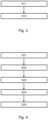
- FIG. 1 schematically shows a flow chart of a method for producing the line pipe 100.
- the line pipe 100 can be configured or produced as described above and/or below.
- the medium pipe 102 is inserted into the casing 106 and/or provided with the casing 106.
- the thermal insulation is arranged in a discontinuous or continuous mode between the medium pipe 102 and the casing 106, wherein in the space between the medium pipe 102 and the casing 106 a liquid and / or foaming composition, such as Plastic composition introduced as thermal insulation, for example filled and / or injected and / or sprayed.
- the liquid or foaming composition such as a plastic composition
- the liquid or foaming composition can be designed as described above and/or below.
- at least one isocyanate component and at least one polyol can be brought together in a mixing head, which are then filled and/or injected and/or sprayed into the space between the medium pipe 102 and the casing 106 as a mixed, reactive, foaming polyurethane system.
- the then hardened plastic foam then forms the thermal insulation, which can be configured as described above and/or below.
- the medium pipe 102 can be introduced together with the casing 106 into a back conveyor and the annular gap between the medium pipe 102 and the casing 106 can be introduced with the liquid and/or foaming composition, such as a plastic composition, as thermal insulation.
- the casing 106 can be provided with the liquid and/or foaming composition, such as a plastic composition, and then inserted into the jaw belt along with the carrier tube 102 .
- FIG. 12 schematically shows a flow chart of a method for manufacturing the conduit 100 by means of a continuous process.
- the conduit 100 can be configured or manufactured as described above and/or below.
- a film such as a separating film, is formed around the at least one medium pipe 102, such as being laid and/or wrapped.
- a step S22 the thermal insulation 104 is applied and/or applied to the medium pipe 102 .
- a liquid and / or foaming Composition such as plastic composition
- the liquid and/or foaming composition such as plastic composition
- the liquid or foaming composition can be designed as described above and/or below.
- At least one isocyanate component and at least one polyol can be combined in a mixing head, which is then applied and/or applied as a mixed, reactive, foaming polyurethane system to the medium pipe 102, in particular to the outer surface of the medium pipe 102 or its protective jacket 112 is introduced into the space between the foil and the at least one medium pipe 102 .
- a step S23 the film is formed into a film tube, longitudinal edges of the film being welded and/or glued.
- the thermal insulation 104 is formed smooth or wavy, at least in its surface region, and/or the film is formed using a forming tool, such as a jaw band.
- a step S25 the casing 106 is then applied to the shaped thermal insulation 104 or to the shaped film, for example extruded, such as extruded on.
- the then hardened plastic foam then forms the thermal insulation, which can be configured as described above and/or below.
- isolated features can also be selected from the combinations of features disclosed here and used in combination with other features to delimit the subject matter of the claim, eliminating any structural and/or functional relationship that may exist between the features.
- the order and/or number of all steps of the method or methods can be varied and/or combined. The methods can be combined with one another.
Abstract
Thermisch gedämmtes, flexibles Leitungsrohr (100), umfassend zumindest ein Mediumrohr (102), eine um das Mediumrohr (102) herum angeordnete Wärmedämmung (104) und eine um die Wärmedämmung (104) herum angeordnete Ummantelung (106), wobei das zumindest eine Mediumrohr (102) ein Innenrohr (108) aus thermoplastischem Kunststoff, eine um das Innenrohr (108) herum angeordnete Verstärkungsschicht (110) und einen um die Verstärkungsschicht (110) herum angeordneten Schutzmantel (112) aufweist, sowie Verfahren zur Herstellung eines solchen thermisch gedämmten, flexiblen Leitungsrohrs (100).Thermally insulated, flexible line pipe (100), comprising at least one medium pipe (102), thermal insulation (104) arranged around the medium pipe (102) and a casing (106) arranged around the thermal insulation (104), the at least one medium pipe (102) has an inner pipe (108) made of thermoplastic material, a reinforcement layer (110) arranged around the inner pipe (108) and a protective jacket (112) arranged around the reinforcement layer (110), and a method for producing such a thermally insulated, flexible conduit (100).
Description
Die Erfindung betrifft ein thermisch gedämmtes, flexibles Leitungsrohr. Außerdem betrifft die Erfindung ein Verfahren zur Herstellung eines thermisch gedämmten, flexiblen Leitungsrohrs.The invention relates to a thermally insulated, flexible conduit. The invention also relates to a method for producing a thermally insulated, flexible conduit.
Als flexible Leitungsrohre kommen oft faserverstärke Kunststoffrohre zum Einsatz, die zum Transport unterschiedlicher Medien, wie Wasser, Öl oder Gas, dienen, beispielsweise bei der Onshore- oder Offshore-Förderung für den Transport an Land oder über dem Meeresboden. Flexible Leitungsrohre finden auch beim Fernwärmeleitungsbau Verwendung, um Medien für Wasser- und Heizungsversorgungsanlagen zu transportieren. Insbesondere weisen faserverstärke Kunststoffrohre, wie thermoplastische Kompositrohre ("Thermoplastic Composite Pipes", TCP), eine hohe Druckbeständigkeit mit Arbeitsdrücken zwischen 40 bis 300 bar auf und ermöglichen so einen Transport des Mediums über lange Strecken.Fiber-reinforced plastic pipes are often used as flexible line pipes, which are used to transport different media such as water, oil or gas, for example in onshore or offshore production for transport on land or above the sea floor. Flexible pipelines are also used in district heating pipeline construction to transport media for water and heating supply systems. In particular, fiber-reinforced plastic pipes, such as thermoplastic composite pipes ("Thermoplastic Composite Pipes", TCP), have a high pressure resistance with working pressures of between 40 and 300 bar and thus enable the medium to be transported over long distances.
Thermoplastische Kompositrohre weisen üblicherweise eine Innenlage aus ein- oder mehrschichtigen Innenliner aus thermoplastischem Material auf. Auf diese wird eine Kompositlage, zum Beispiel durch Aufwickeln faserverstärkter Tapes, aufgebracht. Derartige Kompositrohre sind beispielsweise aus dem Dokument
Beim Transport eines, insbesondere warmen oder heißen, Mediums über weite Strecken mittels thermoplastischer Kompositrohre kann es jedoch zu Wärmeverlusten kommen. Die Wärmeverluste können dazu führen, dass sich die Fließfähigkeit des transportierten Mediums verändert oder ein Temperaturniveau für eine nachfolgende Anwendung nicht mehr bereitgestellt werden kann. In solchen Fällen ist dann eine aufwändige und energieintensive Wiedererwärmung des Mediums notwendig. Ich gleicher Weise kann es beim Transport kalter Medien bei hohen Umgebungstemperaturen notwendig werden, das Medium nochmals aufwändig zu Kühlen.However, heat losses can occur when a medium, particularly a warm or hot medium, is transported over long distances using thermoplastic composite pipes. The heat losses can lead to a change in the flowability of the transported medium or to a temperature level no longer being able to be provided for a subsequent application. In such cases, a complex and energy-intensive reheating of the medium is then necessary. I the same way it can be used when transporting cold media at high Ambient temperatures become necessary to cool the medium again, which is costly.
Der Erfindung liegt die Aufgabe zugrunde, ein eingangs genanntes Leitungsrohr strukturell und/oder funktionell zu verbessern. Außerdem liegt der Erfindung die Aufgabe zugrunde, ein eingangs genanntes Verfahren zur Herstellung eines Leitungsrohrs funktionell zu verbessern.The object of the invention is to structurally and/or functionally improve a line pipe as mentioned at the outset. In addition, the invention is based on the object of functionally improving a method for the production of a conduit mentioned at the outset.
Die Aufgabe wird gelöst mit einem Leitungsrohr mit den Merkmalen des Anspruchs 1. Außerdem wird die Aufgabe gelöst mit einem Verfahren zum Herstellen eines Leitungsrohrs mit den Merkmalen des Anspruchs 12. Vorteilhafte Ausführungen und/oder Weiterbildungen sind Gegenstand der Unteransprüche.The object is achieved with a line pipe having the features of claim 1. The object is also achieved with a method for producing a line pipe having the features of claim 12. Advantageous designs and/or developments are the subject matter of the dependent claims.
Ein Leitungsrohr kann ein thermisch gedämmtes und/oder flexibles Leitungsrohr sein. Das Leitungsrohr kann zumindest ein Mediumrohr umfassen. Das Leitungsrohr kann beispielsweise zwei, drei, vier oder mehr Mediumrohre umfassen. Das Mediumrohr kann ein Innenrohr, beispielsweise aus Kunststoff, wie thermoplastischem Kunststoff, aufweisen. Das Mediumrohr kann eine um das Innenrohr herum angeordnete Verstärkungsschicht aufweisen. Das Mediumrohr kann einen um die Verstärkungsschicht herum angeordneten Schutzmantel aufweisen.A duct can be a thermally insulated and/or flexible duct. The line pipe can comprise at least one medium pipe. The line pipe can include, for example, two, three, four or more medium pipes. The medium pipe can have an inner pipe, for example made of plastic, such as thermoplastic material. The carrier pipe may have a reinforcement layer arranged around the inner pipe. The carrier pipe may have a protective jacket arranged around the reinforcement layer.
Das Leitungsrohr und/oder dessen Mediumrohr kann zum Transport von unterschiedlichen Medien, wie beispielsweise flüssige oder gasförmige Medien, wie Wasser, Öl oder Gas, dienen und/oder ausgebildet sein. Beispielsweise kann das Innenrohr des Mediumrohrs zum Transport von unterschiedlichen Medien, wie zum Beispiel flüssige oder gasförmige Medien, wie Wasser, Öl, wie Rohöl, oder Gas, wie Rohgas, dienen und/oder ausgebildet sein. Das Leitungsrohr kann zum Einsatz bei Wasser-, Öl- oder Gasnetzen bzw. Wasser-, Öl- oder Gasleitungen dienen und/oder ausgebildet sein. Das Leitungsrohr kann zum Einsatz bei der Onshore- oder Offshore-Förderung bzw. dem Onshore- oder Offshore-Transport für den Transport eines Mediums an Land oder über dem Meeresboden dienen und/oder ausgebildet sein. Das Leitungsrohr kann zum Einsatz in Nah- oder Fernwärmenetzen bzw. Nah- oder Fernwärmeleitungen dienen und/oder ausgebildet sein. Das Leitungsrohr kann zum Einsatz bei Geothermienetzen bzw. Geothermienleitungen dienen und/oder ausgebildet sein. Das Leitungsrohr kann beispielsweise ausgebildet sein, um Medien für Wasser- und Heizungsversorgungsanlagen zu transportieren. Das Leitungsrohr kann zum Einsatz bei Trink- oder Abwasserleitungen dienen und/oder ausgebildet sein.The line pipe and/or its medium pipe can be used and/or designed to transport different media, such as liquid or gaseous media such as water, oil or gas. For example, the inner pipe of the medium pipe can serve and/or be designed to transport different media, such as liquid or gaseous media, such as water, oil, such as crude oil, or gas, such as crude gas. The line pipe can serve and/or be designed for use in water, oil or gas networks or water, oil or gas lines. The line pipe can be used and/or designed for use in onshore or offshore production or onshore or offshore transport for transporting a medium on land or above the seabed. The pipe can serve and/or be designed for use in local or district heating networks or local or district heating lines. The pipe can be used in geothermal networks or geothermal lines and/or be trained. The pipe can be designed, for example, to transport media for water and heating supply systems. The line pipe can be used and/or designed for use in drinking water or waste water lines.
Das Leitungsrohr und/oder dessen Mediumrohr kann ein, beispielsweise flexibles und/oder wickelbares und/oder nichtmetallisches Rohr, insbesondere Verbundrohr, sein. Das Verbundrohr kann ein thermoplastisches Verbundrohr sein. Das Leitungsrohr und/oder dessen Mediumrohr kann biegbar ausgebildet sein. Das Leitungsrohr und/oder dessen Mediumrohr kann so ausgebildet sein, um zu Ringen und/oder auf Trommeln gewickelt zu werden. Das Leitungsrohr und/oder dessen Mediumrohr kann an Terrain-Bedingungen anpassbar sein. Das Leitungsrohr kann einen Innendurchmesser von etwa 30 bis 200 mm aufweisen. Das Leitungsrohr kann einen Außendurchmesser von etwa 76 bis 355 mm aufweisen.The line pipe and/or its medium pipe can be, for example, a flexible and/or coilable and/or non-metallic pipe, in particular a composite pipe. The composite pipe can be a thermoplastic composite pipe. The line pipe and/or its medium pipe can be designed to be bendable. The line pipe and/or its medium pipe can be designed in such a way that it can be wound into rings and/or onto drums. The conduit and/or its carrier pipe can be adaptable to terrain conditions. The conduit can have an inside diameter of about 30 to 200 mm. The conduit can have an outside diameter of about 76 to 355 mm.
Soweit nicht anders angegeben oder es sich aus dem Zusammenhang nicht anders ergibt, beziehen sich die Angaben "axial", "radial" und "in Umfangsrichtung" auf eine Erstreckungsrichtung der Längsachse und/oder Symmetrieachse des Leitungsrohrs und/oder Mediumrohrs. Das Leitungsrohr und/oder dessen Mediumrohr kann konzentrisch zur Längsachse und/oder Symmetrieachse sein. "Axial" entspricht dann einer Erstreckungsrichtung der Längsachse und/oder Symmetrieachse. "Radial" ist dann eine zur Erstreckungsrichtung der Längsachse und/oder Symmetrieachse senkrechte und sich mit der Längsachse und/oder Symmetrieachse schneidende Richtung. "In Umfangsrichtung" entspricht dann einer Kreisbogenrichtung um die Längsachse und/oder Symmetrieachse.Unless otherwise stated or the context indicates otherwise, the terms "axial", "radial" and "in the circumferential direction" refer to a direction of extension of the longitudinal axis and/or axis of symmetry of the conduit and/or medium pipe. The line pipe and/or its medium pipe can be concentric to the longitudinal axis and/or the axis of symmetry. “Axial” then corresponds to an extension direction of the longitudinal axis and/or axis of symmetry. "Radial" is then a direction perpendicular to the direction of extent of the longitudinal axis and/or axis of symmetry and intersecting with the longitudinal axis and/or axis of symmetry. "In the circumferential direction" then corresponds to a circular arc direction around the longitudinal axis and/or axis of symmetry.
Das Mediumrohr kann ein faserverstärktes, beispielsweise thermoplastisches, Kunststoffrohr sein. Das Mediumrohr kann ein Mehrschichtrohr sein. Das Mediumrohr kann ein, beispielsweise thermoplastisches, Verbundrohr sein. Das Mediumrohr kann ein verstärktes, wie faserverstärktes, Verbundrohr sein. Das Mediumrohr kann ein Kompositrohr sein. Das Mediumrohr kann ein thermoplastisches Kompositrohr, wie Thermoplastic Composite Pipe (TCP), sein. Das Mediumrohr kann radial innenseitig am Leitungsrohr angeordnet sein. Das Mediumrohr kann ein Basisrohr oder Trägerrohr sein. Das Mediumrohr kann extrudiert oder pultriert sein oder werden. Das Mediumrohr kann mittels eines Extrusionsverfahrens, beispielsweise Koextrusionsverfahrens, oder Pultrusionsverfahrens hergestellt sein oder werden. Beispielsweise kann das Mediumrohr mittels eines Extruders oder mehreren Extrudern und/oder eines Rohrkopfes hergestellt bzw. extrudiert sein oder werden.The medium pipe can be a fiber-reinforced, for example thermoplastic, plastic pipe. The medium pipe can be a multi-layer pipe. The medium pipe can be a composite pipe, for example a thermoplastic pipe. The service pipe can be a reinforced, such as fiber-reinforced, composite pipe. The service pipe can be a composite pipe. The carrier pipe can be a thermoplastic composite pipe such as Thermoplastic Composite Pipe (TCP). The medium pipe can be arranged radially on the inside of the line pipe. The carrier pipe can be a base pipe or carrier pipe. The service pipe can be extruded or pultruded or become. The medium pipe can be produced by means of an extrusion process, for example a coextrusion process, or a pultrusion process. For example, the medium pipe can be produced or extruded by means of an extruder or a plurality of extruders and/or a pipe head.
Das Innenrohr des Mediumrohrs kann ein Innenliner sein. Das Innenrohr bzw. der Innenliner kann ein- oder mehrschichtig sein. Das Innenrohr kann ein Mehrschichtrohr sein. Das Innenrohr kann ein Basisrohr oder Trägerrohr sein. Das Innenrohr des Mediumrohres kann radial innenseitig am Mediumrohr angeordnet sein. Das Innenrohr kann ein Kunststoffrohr, wie thermoplastisches Kunststoffrohr, sein. Das Innenrohr des Mediumrohrs kann aus, beispielsweise thermoplastischem, Kunststoff hergestellt sein oder werden. Der Kunststoff kann beispielsweise Polyolefin, Polyethylen, Polyethylen mit hoher Dichte (HDPE), Polypropylen oder Polyamid sein oder aufweisen. Das Innenrohr kann extrudiert oder pultriert sein oder werden. Das Innenrohr kann mittels eines Extrusionsverfahrens oder Pultrusionsverfahrens hergestellt sein oder werden. Beispielsweise kann das Innenrohr mittels eines Extruders und/oder eines Rohrkopfes hergestellt bzw. extrudiert sein oder werden.The inner pipe of the carrier pipe can be an inner liner. The inner pipe or the inner liner can have one or more layers. The inner tube can be a multi-layer tube. The inner tube can be a base tube or carrier tube. The inner pipe of the medium pipe can be arranged radially on the inside of the medium pipe. The inner tube can be a plastic tube, such as a thermoplastic plastic tube. The inner pipe of the medium pipe can be made of, for example, thermoplastic plastic. The plastic can be or include, for example, polyolefin, polyethylene, high-density polyethylene (HDPE), polypropylene or polyamide. The inner tube can be extruded or pultruded. The inner tube can be produced by means of an extrusion process or a pultrusion process. For example, the inner tube can be produced or extruded by means of an extruder and/or a tube head.
Die Verstärkungsschicht des Mediumrohrs kann mindestens eine Lage aus verstärkenden Fasern aufweisen. Die Fasern können Glasfasern und/oder Kunststofffasern und/oder Kohlefasern und/der Aramidfasern und/oder Basaltfasern und/oder keramische Fasern sein. Der Querschnitt der Fasern kann kreisförmig, rechteckig, oval, elliptisch oder kokonförmig sein. Die Fasern können als Kurzfasern, Langfasern oder Endlosfasern ausgebildet sein. Die Fasern können als Gewebe oder mit einer unidirektionalen Faserlage ausgebildet sein. Die Verstärkungsschicht des Mediumrohrs kann ein Matrixmaterial aus mit Kunststoff imprägnierten Fasern aufweisen. Der Kunststoff kann ein thermoplastischer Kunststoff sein. Der Kunststoff kann beispielsweise Polyolefin, Polyethylen, Polyethylen mit hoher Dichte (HDPE), Polypropylen oder Polyamid sein oder aufweisen. Das Matrixmaterial kann beispielsweise mittels eines Imprägnierverfahrens, Schmelzauftragverfahrens, Schmelzimprägnierverfahrens, Pulverimprägnierverfahrens oder Pultrusionsverfahrens hergestellt sein oder werden.The reinforcement layer of the carrier pipe can have at least one layer of reinforcing fibers. The fibers can be glass fibers and/or plastic fibers and/or carbon fibers and/or aramid fibers and/or basalt fibers and/or ceramic fibers. The cross-section of the fibers can be circular, rectangular, oval, elliptical, or cocoon-shaped. The fibers can be designed as short fibers, long fibers or endless fibers. The fibers can be constructed as a woven fabric or with a unidirectional fiber layer. The reinforcing layer of the service pipe may comprise a matrix material made from fibers impregnated with plastic. The plastic can be a thermoplastic material. The plastic can be or include, for example, polyolefin, polyethylene, high-density polyethylene (HDPE), polypropylene or polyamide. The matrix material can be produced, for example, by means of an impregnation process, melt application process, melt impregnation process, powder impregnation process or pultrusion process.
Die Verstärkungsschicht des Mediumrohrs kann in radialer Richtung zwischen dem Innenrohr und dem Schutzmantel des Mediumrohrs angeordnet sein. Die Verstärkungsschicht des Mediumrohrs kann mindestens eine erste Lage aus verstärkendem Band aufweisen. Die erste Lage aus verstärkendem Band kann im Wesentlichen spiralförmig in einer ersten spiralförmigen Richtung um das Innenrohr herumgewickelt sein oder werden. Die Verstärkungsschicht kann mindestens eine zweite Lage aus verstärkendem Band aufweisen. Die zweite Lage aus verstärkendem Band kann im Wesentlichen spiralförmig um das Innenrohr und/oder die erste Lage aus verstärkendem Band in einer zweiten spiralförmigen Richtung, beispielsweise entgegen der ersten spiralförmigen Richtung, herumgewickelt sein oder werden. Es können mehrere, wie drei, vier oder mehr, Lagen aus verstärkendem Band vorgesehen sein, welche jeweils in einer spiralförmigen Richtung, insbesondere in unterschiedlichen spiralförmigen Richtungen, um das Innenrohr herumgewickelt sind oder werden. Die mehreren Lagen aus verstärkendem Band können wie die erste und/oder zweite Lage aus verstärkendem Band ausgebildet sein.The reinforcement layer of the medium pipe can be arranged in the radial direction between the inner pipe and the protective jacket of the medium pipe. The reinforcing layer of the carrier pipe may include at least a first layer of reinforcing tape. The first layer of reinforcing tape may be substantially helically wrapped around the inner tube in a first helical direction. The reinforcement layer may include at least a second layer of reinforcing tape. The second layer of reinforcing tape may be substantially helically wrapped around the inner tube and/or the first layer of reinforcing tape in a second helical direction, for example counter to the first helical direction. There may be several, such as three, four or more layers of reinforcing tape, each of which is or will be wrapped around the inner tube in a helical direction, particularly in different helical directions. The multiple layers of reinforcing tape may be configured like the first and/or second layers of reinforcing tape.
Die erste Lage aus verstärkendem Band kann ein verstärkendes Band umfassen bzw. sein, welches mit Kunststoff imprägnierte Fasern aufweist. Die zweite Lage aus verstärkendem Band kann ein verstärkendes Band umfassen bzw. sein, welches mit Kunststoff imprägnierte Fasern aufweist. Der Kunststoff kann ein thermoplastischer Kunststoff sein. Der Kunststoff kann beispielsweise Polyolefin, Polyethylen, Polyethylen mit hoher Dichte (HDPE), Polypropylen oder Polyamid sein oder aufweisen. Die Fasern der ersten und/oder zweiten Lage aus verstärkendem Band können unidirektional angeordnet und/oder ausgerichtet sein oder werden. Die erste und/oder zweite Lage aus verstärkendem Band kann/können ein mit Kunststoff imprägniertes Faserband, beispielsweise Endlosfasern, Fasergewebe oder Fasergewirk, aufweisen. Der Kunststoff kann ein thermoplastischer Kunststoff sein. Der Kunststoff kann beispielsweise Polyolefin, Polyethylen, Polyethylen mit hoher Dichte (HDPE), Polypropylen oder Polyamid sein oder aufweisen. Die Fasern der ersten und/oder zweiten Lage aus verstärkendem Band können Verstärkungsfasern, beispielsweise Glasfasern und/oder Kunststofffasern und/oder Kohlefasern und/der Aramidfasern und/oder Basaltfasern und/oder keramische Fasern, sein. Der Querschnitt der Fasern kann kreisförmig, rechteckig, oval, elliptisch oder kokonförmig sein. Die Fasern können als Kurzfasern, Langfasern oder Endlosfasern ausgebildet sein. Die Fasern können als Gewebe oder Gewirk oder mit einer unidirektionalen Faserlage ausgebildet und/oder angeordnet sein. Die erste und/oder zweite Lage aus verstärkendem Band kann auch als Tape, wie faserverstärktes Tape, bezeichnet werden. Die erste und/oder zweite Lage aus verstärkendem Band kann beispielsweise mittels eines Imprägnierverfahrens, Schmelzauftragverfahrens, Schmelzimprägnierverfahrens, Pulverimprägnierverfahrens oder Pultrusionsverfahrens hergestellt sein oder werden.The first layer of reinforcing tape may comprise a reinforcing tape having fibers impregnated with plastic. The second layer of reinforcing tape may comprise a reinforcing tape having fibers impregnated with plastic. The plastic can be a thermoplastic material. The plastic can be or include, for example, polyolefin, polyethylene, high-density polyethylene (HDPE), polypropylene or polyamide. The fibers of the first and/or second layers of reinforcing tape may be or will be arranged and/or aligned unidirectionally. The first and/or second layer of reinforcing tape may comprise a plastics impregnated fibrous tape such as continuous filaments, woven or knitted fabrics. The plastic can be a thermoplastic material. The plastic can be or include, for example, polyolefin, polyethylene, high-density polyethylene (HDPE), polypropylene or polyamide. The fibers of the first and/or second layer of reinforcing tape can be reinforcing fibers, for example glass fibers and/or plastic fibers and/or carbon fibers and/or aramid fibers and/or basalt fibers and/or ceramic fibers. The cross-section of the fibers can be circular, rectangular, oval, elliptical, or cocoon-shaped be. The fibers can be designed as short fibers, long fibers or endless fibers. The fibers can be designed and/or arranged as a woven or knitted fabric or with a unidirectional fiber layer. The first and/or second layer of reinforcing tape may also be referred to as tape, such as fiber reinforced tape. The first and/or second layer of reinforcing tape can be produced, for example, by means of an impregnation process, melt application process, melt impregnation process, powder impregnation process or pultrusion process.
Die Verstärkungsschicht kann mit dem Innenrohr des Mediumrohrs fest verbunden sein oder werden. Die Verstärkungsschicht kann mit der radial außenseitigen Fläche, wie Außenfläche oder Oberfläche, des Innenrohrs des Mediumrohrs fest verbunden sein oder werden. Die erste und/oder zweite Lage aus verstärkendem Band oder die mehreren Lagen aus verstärkendem Band kann/können mit dem Innenrohr des Mediumrohrs fest verbunden sein oder werden. Die Verstärkungsschicht und/oder dessen erste und/oder zweite Lage aus verstärkendem Band kann mit der äußeren Oberfläche bzw. radial außenseitigen Fläche, wie Außenfläche oder Oberfläche, des Innenrohrs des Mediumrohrs fest verbunden sein oder werden. Die Verbindung kann beispielsweise stoffschlüssig, wie verklebt, verschweißt oder verschmolzen, und/oder kraftschlüssig sein. Beispielsweise kann/können die erste und/oder zweite Lage aus verstärkendem Band mit dem Innenrohr des Mediumrohrs, insbesondere mit der äußeren Oberfläche des Innenrohrs, schmelzverbundartig, wie zum Beispiel verklebt, verschweißt oder verschmolzen, und/oder mittels einer kraftschlusseffektiven Bindungsmethode fest miteinander verbunden sein oder werden. Eine solche Verbindung kann auch als "fester Verbund" und/oder "bonded" bezeichnet werden.The reinforcing layer can be or will be permanently connected to the inner pipe of the medium pipe. The reinforcing layer can be or will be firmly connected to the radially outer surface, such as the outer surface or surface, of the inner pipe of the medium pipe. The first and/or second layer of reinforcing tape or multiple layers of reinforcing tape may be or will be fixedly connected to the inner pipe of the carrier pipe. The reinforcing layer and/or its first and/or second layer of reinforcing tape can be or will be firmly connected to the outer surface or radially outer surface, such as the outer surface or surface, of the inner pipe of the carrier pipe. The connection can be materially bonded, such as glued, welded or fused, and/or non-positive. For example, the first and/or second layer of reinforcing tape can be connected to the inner pipe of the carrier pipe, in particular to the outer surface of the inner pipe, in a fusion-bonded manner, such as glued, welded or fused, and/or by means of a non-positive bonding method or become. Such a connection can also be referred to as a “firm compound” and/or “bonded”.
Die Verstärkungsschicht kann mit dem Schutzmantel des Mediumrohrs fest verbunden sein oder werden. Die Verstärkungsschicht kann mit der radial innenseitigen Fläche, wie Innenfläche oder Oberfläche, des Schutzmantels des Mediumrohrs fest verbunden sein oder werden. Die erste und/oder zweite Lage aus verstärkendem Band oder die mehreren Lagen aus verstärkendem Band kann/können mit dem Schutzmantel des Mediumrohrs fest verbunden sein oder werden. Die Verstärkungsschicht und/oder dessen erste und/oder zweite Lage aus verstärkendem Band kann mit der inneren Oberfläche bzw. radial innenseitigen Fläche, wie Innenfläche oder Oberfläche, des Schutzmantels des Mediumrohrs fest verbunden sein oder werden. Die Verbindung kann beispielsweise stoffschlüssig, wie verklebt, verschweißt oder verschmolzen, und/oder kraftschlüssig sein. Beispielsweise kann/können die erste und/oder zweite Lage aus verstärkendem Band mit dem Schutzmantel des Mediumrohrs, insbesondere mit der inneren Oberfläche des Schutzmantels, schmelzverbundartig, wie zum Beispiel verklebt, verschweißt oder verschmolzen, und/oder mittels einer kraftschlusseffektiven Bindungsmethode fest miteinander verbunden sein oder werden. Eine solche Verbindung kann auch als "fester Verbund" und/oder "bonded" bezeichnet werden.The reinforcing layer can be or will be permanently connected to the protective jacket of the carrier pipe. The reinforcing layer can be or will be firmly connected to the radially inner surface, such as the inner surface or surface, of the protective jacket of the carrier pipe. The first and/or second layer of reinforcing tape or multiple layers of reinforcing tape may be or will be permanently bonded to the protective casing of the carrier pipe. The reinforcing layer and / or its first and / or second layer of reinforcing Tape can be or will be firmly connected to the inner surface or radially inner surface, such as the inner surface or surface, of the protective jacket of the carrier pipe. The connection can be materially bonded, such as glued, welded or fused, and/or non-positive. For example, the first and/or second layer of reinforcing tape can be connected to the protective casing of the medium pipe, in particular to the inner surface of the protective casing, in a fusion-bonded manner, such as glued, welded or fused, and/or by means of a non-positive bonding method or become. Such a connection can also be referred to as a “firm compound” and/or “bonded”.
Der Schutzmantel des Mediumrohres kann ein äußerer Mantel des Mediumrohres sein. Der Schutzmantel des Mediumrohres kann radial außenseitig am Mediumrohr angeordnet sein. Der Schutzmantel des Mediumrohres kann ein Rohr, wie Kunststoffrohr, oder eine Folie, wie Kunststofffolie, sein. Der Schutzmantel kann ein Folienschlauch, wie Kunststofffolienschlauch, sein. Der Schutzmantel des Mediumrohres kann aus, beispielsweise thermoplastischem, Kunststoff hergestellt sein oder werden. Der Kunststoff kann beispielsweise Polyolefin, Polyethylen, Polyethylen mit hoher Dichte (HDPE), Polypropylen oder Polyamid sein oder aufweisen. Der Schutzmantel kann extrudiert sein oder werden. Der Schutzmantel kann mittels eines Extrusionsverfahrens hergestellt sein oder werden. Beispielsweise kann der Schutzmantel mittels eines Extruders und/oder eines Rohrkopfes hergestellt bzw. extrudiert sein oder werden.The protective jacket of the carrier pipe can be an outer jacket of the carrier pipe. The protective jacket of the medium pipe can be arranged radially on the outside of the medium pipe. The protective jacket of the medium pipe can be a pipe, such as a plastic pipe, or a film, such as a plastic film. The protective jacket can be a film tube, such as a plastic film tube. The protective jacket of the medium pipe can be made of, for example, thermoplastic, plastic. The plastic can be or include, for example, polyolefin, polyethylene, high-density polyethylene (HDPE), polypropylene or polyamide. The protective jacket can be or will be extruded. The protective jacket can be or will be produced by means of an extrusion process. For example, the protective jacket can be produced or extruded by means of an extruder and/or a pipe head.
Das Mediumrohr kann einen Innendurchmesser von etwa 30 bis 200 mm aufweisen. Das Mediumrohr kann einen Außendurchmesser von etwa 40 bis 265 mm aufweisen. Das Mediumrohr kann eine Wanddicke von etwa 5,0 bis 32,5 mm aufweisen.The medium pipe can have an inner diameter of about 30 to 200 mm. The medium pipe can have an outside diameter of about 40 to 265 mm. The medium pipe can have a wall thickness of about 5.0 to 32.5 mm.
Das Leitungsrohr kann eine Wärmedämmung aufweisen. Die Wärmedämmung kann um das Mediumrohr herum angeordnet sein. Das Leitungsrohr kann eine Ummantelung aufweisen. Die Ummantelung kann um die Wärmedämmung herum angeordnet sein. Die Wärmedämmung kann in radialer Richtung zwischen dem Mediumrohr und der Ummantelung des Leitungsrohrs angeordnet sein.The pipe can have thermal insulation. The thermal insulation can be arranged around the medium pipe. The conduit can have a jacket. The casing can be arranged around the thermal insulation. The thermal insulation can be arranged in the radial direction between the medium pipe and the casing of the line pipe.
Die Wärmedämmung kann mit dem Mediumrohr fest verbunden sein oder werden. Die Wärmedämmung kann mit dem Schutzmantel des Mediumrohrs fest verbunden sein oder werden. Die Wärmedämmung kann mit der äußeren Oberfläche des Mediumrohrs und/oder dessen Schutzmantels fest verbunden sein oder werden. Die Wärmedämmung kann mit einer radial außenseitigen Fläche, wie Außenfläche oder Oberfläche, des Mediumrohrs und/oder dessen Schutzmantels fest verbunden sein oder werden. Die Verbindung kann beispielsweise stoffschlüssig, wie verklebt, verschweißt oder verschmolzen, und/oder kraftschlüssig sein. Eine solche Verbindung kann auch als "fester Verbund" und/oder "bonded" bezeichnet werden. Die Verbindung kann durch die Wärmedämmung selbst verursacht sein. Die Wärmedämmung kann klebende Eigenschaften aufweisen.The thermal insulation can be or will be permanently connected to the medium pipe. The thermal insulation can be or will be permanently connected to the protective jacket of the medium pipe. The thermal insulation can be or will be permanently connected to the outer surface of the carrier pipe and/or its protective jacket. The thermal insulation can be or will be firmly connected to a radially outside surface, such as an outer surface or surface, of the medium pipe and/or its protective jacket. The connection can be materially bonded, such as glued, welded or fused, and/or non-positive. Such a connection can also be referred to as a “firm compound” and/or “bonded”. The connection can be caused by the thermal insulation itself. The thermal insulation can have adhesive properties.
Die Wärmedämmung kann mit der Ummantelung des Leitungsrohrs fest verbunden sein oder werden. Die Wärmedämmung kann mit der inneren Oberfläche der Ummantelung fest verbunden sein oder werden. Die Wärmedämmung kann mit einer radial innenseitigen Fläche, wie Innenfläche oder Oberfläche, der Ummantelung des Leitungsrohrs fest verbunden sein oder werden. Die Verbindung kann beispielsweise stoffschlüssig, wie verklebt, verschweißt oder verschmolzen, und/oder kraftschlüssig sein. Eine solche Verbindung kann auch als "fester Verbund" und/oder "bonded" bezeichnet werden. Die Verbindung kann durch die Wärmedämmung selbst verursacht sein.The thermal insulation can be or will be permanently connected to the casing of the pipe. The thermal insulation can be or will be firmly connected to the inner surface of the casing. The thermal insulation can be firmly connected to a radially inner surface, such as an inner surface or surface, of the casing of the pipe. The connection can be materially bonded, such as glued, welded or fused, and/or non-positive. Such a connection can also be referred to as a “firm compound” and/or “bonded”. The connection can be caused by the thermal insulation itself.
Die Wärmedämmung kann zur thermischen Isolation, insbesondere eines im Mediumrohr bzw. im Innenrohr des Mediumrohrs vorhandenen Mediums, dienen. Die Wärmedämmung kann einen Schaumstoff umfassen und/oder daraus hergestellt sein oder werden. Der Schaumstoff kann ein offenzelliger oder geschlossenzelliger Schaumstoff sein. Der Schaumstoff kann ein wärmedämmender Schaumstoff sein und/oder aus einem wärmedämmenden Material hergestellt sein oder werden. Die Wärmedämmung und/oder der Schaumstoff kann einen Kunststoffschaum, beispielsweise einen aufgeschäumten Kunststoffschaum, umfassen und/oder daraus hergestellt sein oder werden. Der Kunststoffschaum kann beispielsweise auf der Basis von Polyurethan (PUR), Polyisocyanurat (PIR), thermoplastischen Polyester oder thermoplastischen Polyolefin hergestellt sein oder werden. Der Kunststoffschaum kann zum Beispiel Polyurethanschaum (PUR), wie Polyurethan-Hartschaum, oder Polyisocyanurat-schaum, wie Polyiso-Hartschaum (PIR), sein. Die Wärmedämmung und/oder dessen Schaumstoff bzw. Kunststoffschaum kann eine Dichte von etwa 40 bis 80 kg/m3 und/oder eine Druckfestigkeit von 0,1 bis 0,5 MPa aufweisen.The thermal insulation can be used for thermal insulation, in particular of a medium present in the medium pipe or in the inner pipe of the medium pipe. The thermal insulation can comprise and/or be made from a foam. The foam can be an open cell or closed cell foam. The foam can be a heat-insulating foam and/or can be made from a heat-insulating material. The thermal insulation and/or the foam can include and/or be or will be made from a plastic foam, for example a foamed plastic foam. The plastic foam can be produced, for example, on the basis of polyurethane (PUR), polyisocyanurate (PIR), thermoplastic polyester or thermoplastic polyolefin. The plastic foam can be, for example, polyurethane foam (PUR), such as rigid polyurethane foam, or polyisocyanurate foam, such as rigid polyiso foam (PIR). The thermal insulation and/or its foam or plastic foam can have a density of about 40 to 80 kg/m 3 and/or a compressive strength of 0.1 to 0.5 MPa.
Die Wärmedämmung kann mit einer Schicht ummantelt sein. Die Schicht kann, beispielsweise in radialer Richtung, zwischen der Wärmedämmung und der Ummantelung des Leitungsrohrs angeordnet sein. Beispielsweise kann die Wärmedämmung mit einer Folie, wie Trennfolie, ummantelt sein. Die Schicht und/oder Folie kann ein Folienschlauch, wie Kunststofffolienschlauch, sein. Die Schicht und/oder Folie kann aus, beispielsweise thermoplastischem, Kunststoff hergestellt sein oder werden. Der Kunststoff kann beispielsweise Polyolefin, Polyethylen, Polyethylen mit hoher Dichte (HDPE), Polypropylen oder Polyamid sein oder aufweisen. Die Schicht und/oder Folie kann extrudiert sein oder werden. Die Schicht und/oder Folie kann mittels eines Extrusionsverfahrens hergestellt sein oder werden. Beispielsweise kann die Schicht und/oder Folie mittels eines Extruders und/oder eines Rohrkopfes oder eines Folienextruders hergestellt bzw. extrudiert sein oder werden.The thermal insulation can be covered with a layer. The layer can be arranged, for example in the radial direction, between the thermal insulation and the casing of the pipe. For example, the thermal insulation can be covered with a film, such as a release film. The layer and/or film can be a film tube, such as a plastic film tube. The layer and/or foil can be made of, for example, thermoplastic plastic. The plastic can be or include, for example, polyolefin, polyethylene, high-density polyethylene (HDPE), polypropylene or polyamide. The layer and/or film can be or will be extruded. The layer and/or foil can be produced by means of an extrusion process. For example, the layer and/or film can be produced or extruded by means of an extruder and/or a pipe head or a film extruder.
Die Wärmedämmung kann als ein- oder mehrlagige Wärmedämmung ausgebildet sein. Die Wärmedämmung kann eine oder mehrere, beispielsweise zwei, drei, vier oder mehr, Schichten, wie Wärmedämmschichten, aufweisen. Jede Schicht der Wärmedämmung kann aus einem wärmedämmenden Material, wie Schaumstoff und/oder Kunststoffschaum, hergestellt sein oder werden. Der Schaumstoff bzw. Kunststoffschaum kann wie vorstehend und/oder nachfolgend beschrieben ausgebildet und/oder hergestellt sein oder werden. Die Schichten der Wärmedämmung können unterschiedlich ausgebildet, beispielsweise mit unterschiedlichen Schaumstoffen bzw. Kunststoffschäumen ausgebildet sein oder werden. Die Schichten der Wärmedämmung können jeweils durch eine Zwischenschicht, wie Folie, voneinander getrennt ausgebildet sein oder werden. Die Zwischenschicht und/oder Folie kann ein Folienschlauch, wie Kunststofffolienschlauch, sein. Die Zwischenschicht und/oder Folie kann aus, beispielsweise thermoplastischem, Kunststoff hergestellt sein oder werden. Der Kunststoff kann beispielsweise Polyolefin, Polyethylen, Polyethylen mit hoher Dichte (HDPE), Polypropylen oder Polyamid sein oder aufweisen. Die Zwischenschicht und/oder Folie kann extrudiert sein oder werden. Die Zwischenschicht und/oder Folie kann mittels eines Extrusionsverfahrens hergestellt sein oder werden. Beispielsweise kann die Zwischenschicht und/oder Folie mittels eines Extruders und/oder eines Rohrkopfes hergestellt bzw. extrudiert sein oder werden.The thermal insulation can be designed as a single or multi-layer thermal insulation. The thermal insulation can have one or more, for example two, three, four or more layers, such as thermal insulation layers. Each layer of thermal insulation can be made of a thermally insulating material such as foam and/or plastic foam. The foam or plastic foam can be configured and/or produced as described above and/or below. The layers of thermal insulation can be designed differently, for example, be or will be designed with different foams or plastic foams. The layers of thermal insulation can each be formed separately from one another by an intermediate layer, such as a film. The intermediate layer and/or film can be a film tube, such as a plastic film tube. The intermediate layer and/or foil can be made of, for example, thermoplastic plastic. The plastic can, for example be or comprise polyolefin, polyethylene, high density polyethylene (HDPE), polypropylene or polyamide. The intermediate layer and/or film can be or will be extruded. The intermediate layer and/or foil can be produced by means of an extrusion process. For example, the intermediate layer and/or film can be produced or extruded by means of an extruder and/or a pipe head.
Die Wärmedämmung kann einen Innendurchmesser von etwa 40 bis 265 mm aufweisen. Die Wärmedämmung kann einen Außendurchmesser von etwa 72bis 348 mm aufweisen. Die Wärmedämmung kann eine Wanddicke von etwa 16 bis 50 mm aufweisen. Eine oder jede Schicht, wie Wärmedämmschicht, der Wärmedämmung kann eine Wanddicke von etwa 16 bis 50 mm aufweisen.The thermal insulation can have an inner diameter of about 40 to 265 mm. The thermal insulation may have an outside diameter of about 72 to 348 mm. The thermal insulation can have a wall thickness of about 16 to 50 mm. One or each layer, such as a thermal insulation layer, of the thermal insulation can have a wall thickness of about 16 to 50 mm.
Die Ummantelung des Leitungsrohrs kann radial außenseitig am Leitungsrohr angeordnet sein oder werden. Die Ummantelung des Leitungsrohrs kann ein Außenrohr, beispielsweise ein flexibles und/oder biegbares Außenrohr, oder eine Folie, beispielsweise ein flexibler Folienschlauch, sein. Die Ummantelung kann aus, beispielsweise thermoplastischem, Kunststoff hergestellt, beispielsweise extrudiert, sein oder werden. Der Kunststoff kann Polyolefin, Polyethylen, Polyethylen mit hoher Dichte (HDPE), Polypropylen oder Polyamid sein oder aufweisen. Die Ummantelung kann eine Kunststofffolie, zum Beispiel ein Kunststofffolienschlauch, sein. Die Ummantelung des Leitungsrohrs kann eine Wanddicke von etwa 1,0 bis 5,0 mm, beispielsweise von etwa 2 mm aufweisen. Beispielsweise kann die Ummantelung mittels eines Extruders und/oder eines Rohrkopfes hergestellt bzw. extrudiert sein oder werden.The casing of the conduit can be or will be arranged radially on the outside of the conduit. The sheathing of the pipe can be an outer pipe, for example a flexible and/or bendable outer pipe, or a film, for example a flexible film tube. The casing can be made of, for example, thermoplastic plastic, for example extruded. The plastic may be or include polyolefin, polyethylene, high density polyethylene (HDPE), polypropylene, or polyamide. The casing can be a plastic film, for example a plastic film tube. The casing of the conduit can have a wall thickness of about 1.0 to 5.0 mm, for example about 2 mm. For example, the casing can be produced or extruded by means of an extruder and/or a pipe head.
Das Leitungsrohr kann eine Folie, wie Trennfolie und/oder Kunststofffolie, aufweisen. Die Folie kann zwischen der Wärmedämmung und der Ummantelung angeordnet sein. Die Folie, beispielsweise die innere Oberfläche der Folie, kann mit der Wärmedämmung fest verbunden, beispielsweise stoffschlüssig, wie verklebt, verschweißt oder verschmolzen, und/oder kraftschlüssig verbunden, sein. Die Folie, beispielsweise die äußere Oberfläche der Folie, kann mit der Ummantelung fest verbunden, beispielsweise stoffschlüssig, wie verklebt, verschweißt oder verschmolzen, und/oder kraftschlüssig verbunden, sein. Die Folie kann ein Schlauch, wie Folienschlauch, sein. Die Folie kann aus, beispielsweise thermoplastischem, Kunststoff hergestellt, beispielsweise extrudiert, sein oder werden. Der Kunststoff kann Polyolefin, Polyethylen, Polyethylen mit geringer Dichte (LD-PE), lineares Polyethylen mit niederer / geringer Dichte (LLD-PE), Polyethylen mit hoher Dichte (HDPE), Polypropylen oder Polyamid sein oder aufweisen. Beispielsweise kann die Folie mittels eines Extruders, wie Folienextruders, hergestellt bzw. extrudiert sein oder werden.The pipe can have a film, such as a separating film and/or plastic film. The foil can be arranged between the thermal insulation and the casing. The film, for example the inner surface of the film, can be firmly connected to the thermal insulation, for example with a material connection, such as glued, welded or fused, and/or with a non-positive connection. The film, for example the outer surface of the film, can be firmly connected to the sheathing, for example cohesively, such as glued, welded or fused, and/or connected in a non-positive manner. The foil can be a tube, like foil tube. The foil can be made of, for example, thermoplastic plastic, for example extruded. The plastic may be or include polyolefin, polyethylene, low-density polyethylene (LD-PE), linear low/low-density polyethylene (LLD-PE), high-density polyethylene (HDPE), polypropylene, or polyamide. For example, the film can be produced or extruded by means of an extruder, such as a film extruder.
Die Wärmedämmung bzw. zumindest ein Oberflächenbereich der Wärmedämmung und/oder die Folie und/oder die Ummantelung des Leitungsrohrs kann glatt und/oder gewellt ausgebildet sein oder werden. Die radial außenseitige Fläche, wie Außenfläche oder Oberfläche, der Wärmedämmung und/oder der Folie und/oder der Ummantelung kann glatt und/oder gewellt ausgebildet sein oder werden. Die Wärmedämmung und/oder die Folie und/oder die Ummantelung des Leitungsrohrs und/oder dessen radial außenseitige Fläche kann gleichmäßig und/oder ungleichmäßig gewellt sein. Die Wärmedämmung und/oder die Folie und/oder die Ummantelung des Leitungsrohrs und/oder dessen radial außenseitige Fläche kann ein Wellenprofil aufweisen. Das Wellenprofil kann Wellentäler und Wellenberge aufweisen. Die Wellentäler können größer, beispielsweise breiter, wie in Längsrichtung des Leitungsrohrs breiter, sein als die Wellenberge. Die Wellenberge können größer, beispielsweise breiter, wie in Längsrichtung des Leitungsrohrs breiter, sein als die Wellentäler. Das Wellenprofil kann Wellenflanken aufweisen. Die Wellenflanken können, beispielsweise steile / steiler, ansteigende und/oder, beispielsweise flache / flacher, abfallende Wellenflanken aufweisen. Die Wärmedämmung und/oder die Folie und/oder die Ummantelung des Leitungsrohrs und/oder dessen radial außenseitige Fläche kann korrugiert ausgebildet sein oder werden. Die Wärmedämmung und/oder die Folie und/oder die Ummantelung des Leitungsrohrs kann flexibel und/oder biegbar ausgebildet sein oder werden. Die Folie und/oder Ummantelung des Leitungsrohrs kann eine Schutzschicht sein.The thermal insulation or at least one surface area of the thermal insulation and/or the foil and/or the casing of the pipe can be smooth and/or corrugated. The radially outer surface, such as the outer surface or surface, of the thermal insulation and/or the film and/or the casing can be smooth and/or corrugated. The thermal insulation and/or the foil and/or the casing of the pipe and/or its radially outer surface can be corrugated uniformly and/or non-uniformly. The thermal insulation and/or the foil and/or the casing of the conduit and/or its radially outer surface can have a corrugated profile. The wave profile can have wave troughs and wave crests. The wave troughs can be larger, for example wider, such as wider in the longitudinal direction of the line pipe, than the wave crests. The wave crests can be larger, for example wider, such as wider in the longitudinal direction of the line pipe, than the wave troughs. The wave profile can have wave flanks. The wave flanks can have, for example, steeper/steeper, rising and/or, for example, flat/flatter, falling wave flanks. The thermal insulation and/or the film and/or the casing of the conduit and/or its radially outer surface can be corrugated. The heat insulation and/or the foil and/or the casing of the pipe can be or become flexible and/or bendable. The film and/or sheathing of the conduit can be a protective layer.
Das Leitungsrohr kann mittels eines Extrusionsverfahrens, beispielsweise Koextrusionsverfahrens, bzw. einer Extrusionsanlage hergestellt sein oder werden. Beispielsweise kann das Leitungsrohr mittels eines Extruders oder mehreren Extrudern und/oder eines Rohrkopfes hergestellt bzw. extrudiert sein oder werden. Das Leitungsrohr kann mittels eines Backenbandverfahrens bzw. einer Backenbandanlage hergestellt sein oder werden.The line pipe can be produced by means of an extrusion process, for example a coextrusion process, or an extrusion plant. For example, the conduit by means of an extruder or more Extruders and / or a pipe head made or extruded or be. The pipe can be or will be produced by means of a back conveyor method or a back conveyor system.
Eine Verwendung eines vorstehend und/oder nachfolgend beschriebenen Leitungsrohrs kann für den Transport von Öl, wie Rohöl, Gas, wie Rohgas, Wasser, Öl-Wasser-Gemisch, Öl-Gas-Gemisch oder anderen aus den genannten Stoffen kombinierte Gemische sein und/oder dienen.A line pipe described above and/or below can be used for the transport of oil, such as crude oil, gas, such as crude gas, water, an oil-water mixture, an oil-gas mixture or other mixtures combined from the substances mentioned and/or serve.
Bei einem Verfahren zur Herstellung eines Leitungsrohrs, wie thermisch gedämmten, flexiblen Leitungsrohrs, kann die Wärmedämmung in diskontinuierlicher oder kontinuierlicher Arbeitsweise zwischen dem Mediumrohr und der Ummantelung angeordnet werden. Bei einem Verfahren zur Herstellung eines Leitungsrohrs, wie thermisch gedämmten, flexiblen Leitungsrohrs, kann in kontinuierlicher Arbeitsweise die Wärmedämmung auf das Mediumrohr aufgebracht werden. Das Leitungsrohr kann wie vorstehend und/oder nachfolgend beschrieben ausgebildet sein oder werden. Das Leitungsrohr kann so hergestellt werden, dass das Leitungsrohr zumindest ein Mediumrohr, eine Wärmedämmung und eine Ummantelung umfasst, wobei das zumindest eine Mediumrohr ein Innenrohr aus thermoplastischem Kunststoff, eine Verstärkungsschicht und einen Schutzmantel aufweist. Die Wärmedämmung kann um das zumindest eine Mediumrohr herum angeordnet bzw. angebracht und/oder befestigt werden. Die Ummantelung kann um die Wärmedämmung herum angeordnet bzw. angebracht und/oder befestigt werden.In a method of manufacturing a duct, such as thermally insulated flexible duct, the thermal insulation may be placed between the service pipe and the cladding in a batch or continuous mode. In a method for producing a line pipe, such as thermally insulated, flexible line pipe, the thermal insulation can be applied to the medium pipe in a continuous operation. The conduit can be designed as described above and/or below. The line pipe can be manufactured in such a way that the line pipe comprises at least one medium pipe, thermal insulation and a casing, the at least one medium pipe having an inner pipe made of thermoplastic material, a reinforcement layer and a protective jacket. The thermal insulation can be arranged or attached and/or fastened around the at least one medium pipe. The casing can be arranged or attached and/or fastened around the thermal insulation.
Das zumindest eine Mediumrohr und/oder dessen Innenrohr kann extrudiert, beispielsweise koextrudiert, werden. Das Innenrohr des Mediumrohrs kann auf einer Trommel aufgewickelt und/oder gelagert und/oder von der Trommel abgewickelt werden. Die Verstärkungsschicht kann auf das Innenrohr des Mediumrohrs aufgebracht werden, beispielsweise durch Aufwickeln bzw. um das Innenrohr herumwickeln. Die Verstärkungsschicht kann mit dem Innenrohr des Mediumrohrs fest verbunden werden, beispielsweise stoffschlüssig, wie verklebt, verschweißt oder verschmolzen, und/oder kraftschlüssig und/oder "gebonded". Der Schutzmantel kann auf das mit der Verstärkungsschicht versehene Innenrohr des Mediumrohrs aufgebracht, beispielsweise extrudiert, wie aufextrudiert, oder aufgewickelt bzw. herumgewickelt werden. Das mit der Verstärkungsschicht versehene Innenrohr des Mediumrohrs kann in den Schutzmantel eingeführt und/oder eingeschoben werden. Der Schutzmantel kann mit der Verstärkungsschicht des Mediumrohrs fest verbunden werden, beispielsweise stoffschlüssig, wie verklebt, verschweißt oder verschmolzen, und/oder kraftschlüssig und/oder "gebonded".The at least one medium pipe and/or its inner pipe can be extruded, for example coextruded. The inner pipe of the carrier pipe can be wound up and/or stored on a drum and/or unwound from the drum. The reinforcement layer can be applied to the inner pipe of the carrier pipe, for example by winding it up or around the inner pipe. The reinforcing layer can be firmly connected to the inner pipe of the medium pipe, for example materially, such as glued, welded or fused, and/or non-positively and/or "bonded". The protective jacket can be applied to the inner pipe of the carrier pipe that is provided with the reinforcement layer, for example extruded, as if extruded on, or wound up or to be wrapped around. The inner pipe of the medium pipe provided with the reinforcing layer can be inserted and/or pushed into the protective jacket. The protective jacket can be firmly connected to the reinforcement layer of the carrier pipe, for example materially, such as glued, welded or fused, and/or non-positively and/or "bonded".
Das Mediumrohr kann auf einer Trommel aufgewickelt und/oder gelagert und/oder von der Trommel abgewickelt werden. Das Mediumrohr kann, beispielsweise kontinuierlich oder diskontinuierlich, bereitgestellt werden. Zum Beispiel kann ein Teil eines Mediumrohrs bereitgestellt werden. Das Teil des Mediumrohrs kann im Wesentlichen geradlinig oder als Formteil bereitgestellt werden. Das Formteil kann gebogen sein oder werden und/oder zumindest abschnittsweise I-, T- oder U-förmig ausgebildet sein oder werden. Beispielsweise kann das Mediumrohr als T-Stück oder als Rohrstange bereitgestellt werden.The carrier pipe can be wound and/or stored on a drum and/or unwound from the drum. The medium pipe can be provided, for example continuously or discontinuously. For example, part of a service pipe can be provided. The part of the service pipe can be provided essentially straight or as a moulding. The molded part can be or become curved and/or be or become I-, T- or U-shaped at least in sections. For example, the medium pipe can be provided as a T-piece or as a pipe rod.
Die Ummantelung kann, beispielsweise kontinuierlich oder diskontinuierlich, bereitgestellt werden. Die Ummantelung kann vorgefertigt sein oder werden. Das Mediumrohr und/oder ein Teil des Mediumrohrs kann in die Ummantelung eingeführt und/oder eingeschoben werden. Zwischen dem Mediumrohr bzw. dem Teil des Mediumrohrs und der Ummantelung können Abstandshalter bereitgestellt werden. Durch die Abstandshalter kann ein Raum, wie Hohlraum, Spalt oder Ringspalt, zwischen dem Mediumrohr und der Ummantelung gebildet werden. In den Raum zwischen dem Mediumrohr und der Ummantelung kann eine flüssige und/oder aufschäumende Zusammensetzung, wie Kunststoffzusammensetzung, als Wärmedämmung eingebracht, beispielsweise eingefüllt und/oder eingespritzt und/oder eingesprüht, werden. Die Wärmedämmung kann wie vorstehend und/oder nachfolgend beschrieben ausgebildet sein oder werden.The cladding may be provided, for example, continuously or discontinuously. The casing can be or will be prefabricated. The medium pipe and/or part of the medium pipe can be inserted and/or pushed into the casing. Spacers may be provided between the service pipe or part of the service pipe and the casing. A space, such as a cavity, gap or annular gap, can be formed between the carrier pipe and the casing by means of the spacers. A liquid and/or foaming composition, such as a plastic composition, can be introduced, for example filled and/or injected and/or sprayed, into the space between the carrier pipe and the casing as thermal insulation. The thermal insulation can be designed as described above and/or below.
Eine flüssige und/oder aufschäumende Zusammensetzung, wie Kunststoffzusammensetzung, kann als Wärmedämmung auf die, insbesondere bereitgestellte, Ummantelung, beispielsweise auf die innere Oberfläche der Ummantelung, aufgebracht werden. Eine flüssige und/oder aufschäumende Zusammensetzung, wie Kunststoffzusammensetzung, kann als Wärmedämmung auf eine Folie, wie Kunststofffolie, aufgebracht werden. Die Folie kann eine Trennfolie sein. Die Folie kann, beispielsweise kontinuierlich oder diskontinuierlich, bereitgestellt werden.A liquid and/or foaming composition, such as a plastic composition, can be applied as thermal insulation to the casing, in particular provided, for example to the inner surface of the casing. A liquid and/or foaming composition, such as a plastic composition, can be applied to a film, such as a plastic film, as thermal insulation. The film can be a release film be. The film can be provided, for example, continuously or discontinuously.
Die mit der flüssigen und/oder aufschäumenden Zusammensetzung bzw. Kunststoffzusammensetzung versehene Ummantelung und/oder Folie kann dann zusammen mit dem Mediumrohr in einem Formwerkzeug, wie Backenband, eingeführt werden.The casing and/or film provided with the liquid and/or foaming composition or plastic composition can then be introduced together with the medium pipe in a mold, such as a jaw belt.
Das Mediumrohr und ein aus einer Folie kontinuierlich gebildeter Folienschlauch kann in einem Formwerkzeug, wie Backenband, bereitgestellt werden. Dabei kann das Mediumrohr innerhalb des Folienschlauches angeordnet werden, beispielsweise so, dass zwischen dem Mediumrohr und dem Folienschlauch ein Raum, wie Hohlraum, Spalt oder Ringspalt, ausgebildet wird. Hierfür können Abstandshalter zwischen dem Mediumrohr und dem Folienschlauch vorgesehen bzw. bereitgestellt werden. In den Raum kann eine flüssige und/oder aufschäumende Zusammensetzung, wie Kunststoffzusammensetzung, als Wärmedämmung eingebracht, beispielsweise eingefüllt und/oder eingespritzt und/oder eingesprüht, werden.The carrier tube and a film tube continuously formed from a film may be provided in a mold such as a jaw belt. The medium pipe can be arranged inside the film tube, for example in such a way that a space, such as a cavity, gap or annular gap, is formed between the medium pipe and the film tube. For this purpose, spacers can be provided or provided between the medium pipe and the film tube. A liquid and/or foaming composition, such as a plastic composition, can be introduced into the room as heat insulation, for example filled and/or injected and/or sprayed.
Die Form des Backenbands, insbesondere dessen innere Oberfläche, kann die Form, wie die radial äußere Oberfläche bzw. Außenschicht, der Ummantelung und/oder der Folie und/oder der Wärmedämmung vorgeben und/oder ausbilden. Beispielsweise kann die innere Oberfläche des Backenbands ein Wellenprofil aufweisen. Das Wellenprofil des Backenbands kann so ausgebildet sein, dass das vorstehend und/oder nachfolgend beschriebene Wellenprofil der Ummantelung und/oder Folie und/oder Wärmedämmung ausgebildet werden kann. Das Backenband kann ein Formwerkzeug sein. Das Formwerkzeug kann Formhälften, beispielsweise zwei Formhälften, aufweisen. Die Formhälften können gegenüberliegend angeordnet sein oder werden. Zwei Formhälften können ein Formwerkzeugpaar bilden. Es können mehrere Formwerkzeugpaare vorgesehen sein. Das Formwerkzeug und/oder dessen Formhälften können mitlaufend ausgebildet sein. Das Formwerkzeug und/oder dessen Formhälften können beheizbar oder kühlbar ausgebildet sein. Die Formhälften bzw. dessen inneren Oberflächen können das Wellenprofil aufweisen. Das Backenband und/oder Formwerkzeug kann dazu ausgebildet sein, das Leitungsrohrs, wie thermisch gedämmte, flexible Leitungsrohr, zu erzeugen bzw. herzustellen.The shape of the jaw band, in particular its inner surface, can specify and/or form the shape, such as the radially outer surface or outer layer, of the casing and/or the foil and/or the thermal insulation. For example, the inner surface of the jaw band can have a corrugated profile. The corrugated profile of the cheek band can be designed in such a way that the corrugated profile of the casing and/or foil and/or thermal insulation described above and/or below can be configured. The jaw band can be a molding tool. The molding tool can have mold halves, for example two mold halves. The mold halves can be or will be arranged opposite one another. Two mold halves can form a mold pair. Several pairs of molds can be provided. The mold and/or its mold halves can be designed to run along. The mold and/or its mold halves can be designed to be heatable or coolable. The mold halves or their inner surfaces can have the corrugated profile. The Jaw band and/or mold may be configured to produce or manufacture the conduit, such as thermally insulated, flexible conduit.
Bei einer diskontinuierlichen Arbeitsweise kann beispielsweise das Mediumrohr in Teilen, wie Stangen / Rohrstangen, oder als vorgefertigte Formteile, wie Bögen oder T-Stücke, herausgeschnitten und/oder vorgefertigt und/oder bereitgestellt werden. Die Stangen / Rohrstangen können unterschiedliche Längen, zum Beispiel bis zu etwa 16 m pro Teil aufweisen. Die Teile des Mediumrohrs können in die Ummantelung und/oder eine Folie, wie Folienschlauch, eingefügt werden, beispielsweise mittels Abstandshaltern. Die Folie kann eine Kunststofffolie und/oder Trennfolie sein. Alternativ können die Teile des Mediumrohrs mit der Ummantelung und/oder Folie versehen werden. Die Ummantelung und/oder Folie kann vorgefertigt sein oder werden. Der Hohlraum zwischen dem Teil des Mediumrohrs und der Ummantelung und/oder Folie kann mit einer flüssigen und/oder aufschäumenden Zusammensetzung, wie Kunststoffzusammensetzung, als Wärmedämmung gefüllt, wie ausgefüllt, werden.In a discontinuous mode of operation, for example, the carrier pipe can be cut out and/or prefabricated and/or provided in parts, such as rods/tube rods, or as prefabricated shaped parts, such as bends or T-pieces. The rods / tube rods can have different lengths, for example up to about 16 m per part. The parts of the medium pipe can be inserted into the casing and/or a film, such as a film tube, for example by means of spacers. The film can be a plastic film and/or release film. Alternatively, the parts of the carrier pipe can be provided with the sheathing and/or foil. The casing and/or film can be or will be prefabricated. The cavity between the part of the service pipe and the casing and/or foil can be filled, as filled, with a liquid and/or foaming composition, such as plastic composition, as thermal insulation.
Bei einer kontinuierlichen Arbeitsweise kann beispielsweise das Mediumrohr auf Trommeln gelagert und/oder mit den Trommeln zur Herstellungsanlage gebracht werden. Eine flüssige und/oder aufschäumenden Zusammensetzung, wie Kunststoffzusammensetzung, kann als Wärmedämmung in einem kontinuierlichen Prozess um das Mediumrohr herum angebracht und/oder aufgebracht werden. Die flüssige und/oder aufschäumenden Zusammensetzung, wie Kunststoffzusammensetzung, kann auf die Ummantelung und/oder eine Folie, wie Folienschlauch und/oder Trennfolie und/oder Kunststofffolie, aufgebracht werden. Das Mediumrohr und die Ummantelung und/oder Folie kann dann in ein Backenband eingeführt werden.In the case of continuous operation, for example, the medium pipe can be stored on drums and/or brought to the production plant with the drums. A liquid and/or foaming composition, such as a plastic composition, can be applied and/or applied around the service pipe as thermal insulation in a continuous process. The liquid and/or foaming composition, such as a plastic composition, can be applied to the casing and/or a film, such as a tubular film and/or separating film and/or plastic film. The carrier pipe and the casing and/or foil can then be inserted into a jaw belt.
Bei einer kontinuierlichen Arbeitsweise kann die Wärmedämmung auf das zumindest eine Mediumrohr aufgebracht und/oder aufgetragen werden, beispielsweise kontinuierlich aufgebracht und/oder aufgetragen werden. Eine flüssige und/oder aufschäumende Kunststoffzusammensetzung kann als Wärmedämmung auf das Mediumrohr, beispielsweise auf die äußere Oberfläche des Mediumrohrs und/oder dessen Schutzmantels, aufgebracht und/oder aufgetragen werden. Die Ummantelung kann, beispielsweise nahtlos, auf die Wärmedämmung, beispielsweise direkt oder indirekt, aufgebracht, beispielsweise extrudiert, wie aufextrudiert, werden.In a continuous mode of operation, the thermal insulation can be applied and/or applied to the at least one medium pipe, for example applied and/or applied continuously. A liquid and/or foaming plastic composition can be applied and/or applied as thermal insulation to the medium pipe, for example to the outer surface of the medium pipe and/or its protective jacket. The shroud can, for example seamlessly, be applied to the thermal insulation, for example directly or indirectly, for example extruded, such as being extruded on.
Das zumindest eine Mediumrohr kann von einer Trommel abgewickelt werden. Das zumindest eine Mediumrohr kann in Längsrichtung des Mediumrohrs bereitgestellt und/oder transportiert und/oder von der Trommel abgezogen werden. Das zumindest eine Mediumrohr kann, beispielsweise mittels einer Heizeinrichtung, wie Infrarotheizeinrichtung oder Elektrowiderstandsheizeinrichtung, vorerwärmt bzw. vorgewärmt werden. Eine Folie, wie Kunststofffolie und/oder Trennfolie, kann um das Mediumrohr herum geformt, wie gelegt und/oder gewickelt, werden. Eine flüssige und/oder aufschäumende Kunststoffzusammensetzung kann als Wärmedämmung, beispielsweise mittels einer Pistole oder mittels eines Mischkopfs, in einen Raum, wie Spalt, zwischen der Folie und dem zumindest einen Mediumrohr eingebracht, wie eingespritzt, eingesprüht oder eingelassen, werden. Unter Einlassen kann auch ein Einlaufen oder Einfließen lassen der flüssigen und/oder aufschäumenden Kunststoffzusammensetzung in den Raum zwischen der Folie und dem zumindest einen Mediumrohr verstanden werden. Der Raum kann ein Dämmstoffausformungsbereich sein. Der Dämmstoffausformungsbereich kann durch die Folie, insbesondere die Innenseite der Folie, und das zumindest eine Mediumrohr, insbesondere die Außenseite des zumindest einen Mediumrohrs, definiert und/oder gebildet sein. Das Einbringen der flüssigen und/oder aufschäumenden Kunststoffzusammensetzung kann kontinuierlich erfolgen. Die Folie kann zu einem Schlauch, wie Folienschlauch, geformt werden. Dabei können Längskanten der Folie verschweißt und/oder verklebt werden. Die Ausformung der Folie zu einem Schlauch kann kontinuierlich erfolgen. Die Ausformung der Folie zu einem Schlauch kann unmittelbar nach dem Umlegen der Folie um das zumindest eine Mediumrohr und/oder unmittelbar nach dem Einbringen der flüssigen und/oder aufschäumenden Kunststoffzusammensetzung in den durch die Folie und das zumindest eine Mediumrohr definierten und/oder gebildeten Raum erfolgen. Die Wärmedämmung kann zumindest in ihrem Oberflächenbereich und/oder die Folie / Folienschlauch kann/können durch ein Formwerkzeug, wie Backenband, geformt werden, beispielsweise glatt oder wellenförmig geformt werden. Das Formen der Wärmedämmung und/oder der Folie / Folienschlauch kann durch das Formwerkzeug in einem ersten Teilschritt und in einem ersten Teilbereich und in einem weiteren Teilschritt in einem weiteren Teilbereich erfolgen. Die Teilbereiche und/oder Teilschritte können, beispielsweise unmittelbar, hintereinander sein. Das Formen der Wärmedämmung und/oder der Folie / Folienschlauch kann kontinuierlich erfolgen. Die Folie / Folienschlauch kann ausgebildet sein und/oder dazu dienen, ein Haften, wie Anhaften, beispielsweise der Kunststoffzusammensetzung bzw. Wärmedämmung, an dem Formwerkzeug zu verhindern. Das Formwerkzeug kann beheizt oder gekühlt werden. Dadurch kann das Aushärten der Kunststoffzusammensetzung beeinflusst, beispielsweise verzögert oder beschleunigt, und/oder ein Aushärtezeitpunkt eingestellt werden. Die flüssige und/oder aufschäumende Kunststoffzusammensetzung kann aufschäumen und/oder aushärten, beispielsweise vor und/oder während dem Formen durch das Formwerkzeug. Die flüssige und/oder aufschäumende Kunststoffzusammensetzung kann nach dem Formen durch das Formwerkzeug zu der bzw. als Wärmedämmung ausgehärtet sein. Die Ummantelung kann, beispielsweise nahtlos, auf die ausgeformte und/oder ausgehärtete Wärmedämmung und/oder auf die, insbesondere ausgeformte, Folie / Folienschlauch aufgebracht, beispielsweise extrudiert, wie aufextrudiert, werden. Das Extrudieren kann mittels eines Extruders, wie Einschneckenextruder, und/oder mittels eines Rohrkopfes erfolgen. Das Aufbringen der Ummantelung kann kontinuierlich erfolgen. Die Ummantelung kann die Form der äußeren Oberfläche der ausgeformten und/oder ausgehärteten Wärmedämmung und/oder der, insbesondere ausgeformten, Folie / Folienschlauch annehmen und/oder aufweisen. Das Leitungsrohr kann dann mittels einer Kühleinrichtung, wie Kühlungsbadeinrichtung, gekühlt werden und/oder auf eine Trommel aufgewickelt werden. Die Kühleinrichtung und/oder die Kühlungsbadeinrichtung kann eine Wasserkühlungseinrichtung und/oder Kühlwassereinrichtung sein. Die Kühleinrichtung kann Düsen, wie Spritzdüsen, aufweisen, mittels denen Kühlwasser auf das Leitungsrohr gespitzt werden kann.The at least one medium pipe can be unwound from a drum. The at least one medium pipe can be provided and/or transported and/or pulled off the drum in the longitudinal direction of the medium pipe. The at least one medium pipe can be preheated or preheated, for example by means of a heating device, such as an infrared heating device or an electric resistance heating device. A foil, such as plastic foil and/or release liner, may be formed, such as laid and/or wrapped, around the service pipe. A liquid and/or foaming plastic composition can be introduced as thermal insulation, for example by means of a pistol or a mixing head, into a space, such as a gap, between the film and the at least one medium pipe, such as injected, sprayed or let in. Letting in can also be understood as letting the liquid and/or foaming plastic composition flow in or out into the space between the film and the at least one medium pipe. The space may be an insulation molding area. The insulation molding area can be defined and/or formed by the film, in particular the inside of the film, and the at least one carrier pipe, in particular the outside of the at least one carrier pipe. The liquid and/or foaming plastic composition can be introduced continuously. The film can be formed into a tube, such as film tubing. Longitudinal edges of the film can be welded and/or glued. The film can be formed into a tube continuously. The film can be formed into a tube immediately after the film has been folded around the at least one carrier pipe and/or immediately after the liquid and/or foaming plastic composition has been introduced into the space defined and/or formed by the film and the at least one carrier pipe . The thermal insulation can be shaped at least in its surface area and/or the film/film tube can be shaped, for example smooth or wavy, by a shaping tool such as a jaw band. The thermal insulation and/or the foil/foil tube can be formed by the forming tool in a first partial step and in a first sub-area and in a further sub-step in a further sub-area. The partial areas and/or partial steps can be, for example, directly one after the other. The thermal insulation and/or the foil/foil tube can be formed continuously. The film/film tube can be designed and/or used to prevent sticking, such as sticking, for example of the plastic composition or thermal insulation, to the mold. The mold can be heated or cooled. As a result, the curing of the plastic composition can be influenced, for example delayed or accelerated, and/or a curing time can be set. The liquid and/or foaming plastic composition can foam and/or harden, for example before and/or during shaping by the mold. The liquid and/or foaming plastic composition can be hardened after being shaped by the mold to form or as thermal insulation. The sheathing can be applied, for example seamlessly, to the shaped and/or hardened thermal insulation and/or to the film/film tube, in particular shaped, for example extruded or extruded on. The extrusion can be done by means of an extruder, such as a single-screw extruder, and/or by means of a barrel head. The coating can be applied continuously. The casing can assume and/or have the shape of the outer surface of the formed and/or hardened thermal insulation and/or the particularly formed film/film tube. The conduit can then be cooled by means of cooling means, such as cooling bath means, and/or wound on a drum. The cooling device and/or the cooling bath device can be a water cooling device and/or a cooling water device. The cooling device can have nozzles, such as spray nozzles, by means of which cooling water can be sprayed onto the pipe.
Das zumindest eine Mediumrohr kann wie vorstehend und/oder nachfolgend ausgebildet sein oder werden. Die Folie kann wie vorstehend und/oder nachfolgend ausgebildet sein oder werden. Die Ummantelung kann wie vorstehend und/oder nachfolgend ausgebildet sein oder werden. Das Formwerkzeug kann wie vorstehend und/oder nachfolgend ausgebildet sein. Die Zusammensetzung bzw. Kunststoffzusammensetzung kann wie vorstehend und/oder nachfolgend ausgebildet sein oder werden. Die Zusammensetzung bzw. Kunststoffzusammensetzung kann der vorstehend und/oder nachfolgend beschriebene aufschäumende Schaumstoff und/oder Kunststoffschaum sein. Die Wärmedämmung kann durch Aufschäumen und/oder Aushärten der flüssigen und/oder aufschäumenden Zusammensetzung bzw. Kunststoffzusammensetzung ausgebildet werden. Die Zusammensetzung bzw. Kunststoffzusammensetzung kann ein reagierendes bzw. reaktives Kunststoffsystem, beispielsweise ein Polyurethansystem oder Polyisozyanoratsystem, sein. Die Zusammensetzung bzw. Kunststoffzusammensetzung kann ein reaktiver und/oder aufschäumender Schaumstoff und/oder Kunststoffschaum sein. Beispielsweise kann mindestens eine Isocyanatkomponente und mindestens ein Polyol zusammengeführt werden, die das reaktive Kunststoffsystem bilden. Das Kunststoffsystem kann aufgeschäumt und/oder ausgehärtet werden. Die Zusammensetzung / Kunststoffzusammensetzung bzw. das Kunststoffsystem kann mittels eines Mischkopfs gemischt und/oder erzeugt und/oder bereitgesellt werden.The at least one medium pipe can be designed as above and/or below. The film can be designed as above and/or below. The casing can be designed as above and/or below. The mold can be designed as above and/or below. The composition or Plastic composition can be designed as above and/or below. The composition or plastic composition can be the foaming foam and/or plastic foam described above and/or below. The thermal insulation can be formed by foaming and/or curing of the liquid and/or foaming composition or plastic composition. The composition or plastic composition can be a reacting or reactive plastic system, for example a polyurethane system or polyisocyanate system. The composition or plastic composition can be a reactive and/or foaming foam and/or plastic foam. For example, at least one isocyanate component and at least one polyol can be brought together to form the reactive plastic system. The plastic system can be foamed and/or cured. The composition/plastic composition or the plastic system can be mixed and/or produced and/or made available by means of a mixing head.
Eine Vorrichtung zum Herstellen eines thermisch gedämmten, flexiblen Leitungsrohrs kann zumindest eine Vorratstrommel zum Bevorraten eines Mediumrohrs, ein Rollensystem, eine Heizeinrichtung zum Vorwärmen des Mediumrohrs, eine Vorratsspule zum Bevorraten einer Folie, eine Zuführeinrichtung zum Zuführen der Folie, eine Pistole und/oder Mischkopf zum Einbringen eines flüssigen und/oder aufschäumenden Kunststoffzusammensetzung als Wärmedämmung, eine Folienschweißeinrichtung zum Bilden eines Folienschlauchs, ein Formwerkzeug, wie Backenband, zum Formen der Wärmedämmung und/oder Folie, eine Ummantelungsaufbringeinheit, wie Extruder und/oder Rohrkopf, zum Aufbringen einer Ummantelung und/oder eine Kühleinrichtung, wie Kühlungsbadeinrichtung, zum Kühlen des Leitungsrohrs. Die Kühleinrichtung und/oder Kühlungsbadeinrichtung kann eine Wasserkühlungseinrichtung und/oder Kühlwassereinrichtung sein. Die Kühleinrichtung kann Düsen, wie Spritzdüsen, aufweisen, die ausgebildet sind, Kühlwasser auf das Leitungsrohr zu spritzen. Die Vorrichtung kann ferner einen Abzug, wie Bandabzug, und/oder eine weitere Vorratstrommel zum Aufwickeln und/oder Bevorraten des hergestellten Leitungsrohrs aufweisen. Die Vorrichtung zum Herstellen des Leitungsrohrs kann zur Durchführung zumindest eines der vorstehend und/oder nachfolgend beschriebenen Verfahren ausgebildet und/oder eingerichtet sein. Die Vorrichtung zum Herstellen des Leitungsrohrs kann ausgebildet und/oder eingerichtet sein, das vorstehend und/oder nachfolgend beschriebene Leitungsrohr herzustellen.A device for producing a thermally insulated, flexible pipe can have at least one storage drum for storing a medium pipe, a roller system, a heating device for preheating the medium pipe, a storage spool for storing a film, a feed device for feeding the film, a gun and/or mixing head for Introduction of a liquid and/or foaming plastic composition as thermal insulation, a film welding device for forming a film tube, a forming tool, such as a jaw band, for forming the thermal insulation and/or film, a coating application unit, such as an extruder and/or pipe head, for applying a coating and/or a cooling means, such as cooling bath means, for cooling the duct. The cooling device and/or cooling bath device can be a water cooling device and/or cooling water device. The cooling device can have nozzles, such as spray nozzles, which are designed to spray cooling water onto the pipe. The device can also have a take-off, such as a strip take-off, and/or a further storage drum for winding up and/or storing the pipe that has been produced. The device for producing the conduit can be used to carry out at least one of the above and/or be designed and/or set up in the methods described below. The device for producing the conduit can be designed and/or set up to produce the conduit described above and/or below.
Mit der Erfindung kann eine gleichmäßige Wärmedämmung an allen Stellen des Leitungsrohrs ermöglicht werden. Wärmeverluste des zu transportierenden Mediums können vermieden oder zumindest stark reduziert werden. Die Fließfähigkeit des zu transportierenden Mediums kann zumindest im Wesentlichen unverändert aufrechterhalten werden. Geforderte Temperaturniveaus können eingehalten werden.With the invention, a uniform thermal insulation can be made possible at all points of the pipe. Heat losses from the medium to be transported can be avoided or at least greatly reduced. The flowability of the medium to be transported can be maintained at least essentially unchanged. Required temperature levels can be maintained.
Nachfolgend werden Ausführungsbeispiele der Erfindung unter Bezugnahme auf Figuren näher beschrieben, dabei zeigen schematisch und beispielhaft:
- Fig. 1
- ein thermisch gedämmtes, flexibles Leitungsrohr im Querschnitt;
- Fig. 2
- das Leitungsrohr gemäß
Fig. 1 im Längsschnitt; - Fig. 3
- ein Flussdiagramm eines Verfahrens zur Herstellung des Leitungsrohrs gemäß
Fig. 1 und 2 ; und - Fig. 4
- ein Flussdiagramm eines weiteren Verfahrens zur Herstellung des Leitungsrohrs gemäß
Fig. 1 und 2 .
- 1
- a thermally insulated, flexible conduit in cross-section;
- 2
- the conduit according to
1 in longitudinal section; - 3
- a flow chart of a method for manufacturing the conduit according to FIG
Figures 1 and 2 ; and - 4
- a flow chart of a further method for manufacturing the conduit according to FIG
Figures 1 and 2 .
Das Mediumrohr 102 ist als ein flexibles, wickelbares und nichtmetallisches, thermoplastisches Verbundrohr ("thermoplastic composite pipe", TCP) ausgebildet. Das Mediumrohr 102 weist ein Innenrohr 108, wie Innenliner, auf, in dem das zu transportierende Medium geführt bzw. transportiert werden kann. Das Innenrohr 108 ist aus einem thermoplastischen Kunststoff, wie einem Polyethylen mit hoher Dichte (HDPE), hergestellt, beispielsweise extrudiert. Das Mediumrohr 102 weist ferner eine um das Innenrohr 108 angeordnete Verstärkungsschicht 110 auf. Die Verstärkungsschicht kann beispielsweise eine oder mehrere, wie zwei, Lagen aus verstärkendem Band umfassen, die mit Kunststoff imprägnierte, insbesondere unidirektional angeordnete, Fasern, beispielsweise Glasfasern und/oder Kunststofffasern und/oder Kohlefasern und/oder Aramidfasern, aufweisen. Die Lagen aus verstärkendem Band sind in unterschiedlichen Richtungen spiralförmig um das Innenrohr 108 herum angeordnet und mit diesem fest verbunden, wie verschweißt oder verklebt. Das Mediumrohr 102 weist ferner einen aus Kunststoff hergestellten Schutzmantel 112 auf. Der Schutzmantel 112 ist um die Verstärkungsschicht 110 des Mediumrohrs 102 herum angeordnet und mit dieser fest verbunden, wie verschweißt oder verklebt. Die Wärmedämmung 104 ist um den Schutzmantel 112 des Mediumrohrs 102 herum angeordnet und mit dem den Schutzmantel 112 fest verbunden, beispielsweise verschweißt oder verklebt.The
Das Leitungsrohr 100 ist konzentrisch zu einer Achse 114, wie Längsachse und/oder Symmetrieachse.The
In einem Schritt S11 wird das Mediumrohr 102 in die Ummantelung 106 eingeführt und/oder mit der Ummantelung 106 versehen.In a step S11, the
In einem Schritt S12 wird die Wärmedämmung in diskontinuierlicher oder kontinuierlicher Arbeitsweise zwischen dem Mediumrohr 102 und der Ummantelung 106 angeordnet, wobei in den Raum zwischen dem Mediumrohr 102 und der Ummantelung 106 eine flüssige und/oder aufschäumende Zusammensetzung, wie Kunststoffzusammensetzung, als Wärmedämmung eingebracht, beispielsweise eingefüllt und/oder eingespritzt und/oder eingesprüht, wird. Die flüssige bzw. aufschäumende Zusammensetzung, wie Kunststoffzusammensetzung, kann wie vorstehend und/oder nachfolgend beschrieben ausgebildet sein oder werden. Beispielsweise kann mindestens eine Isocyanatkomponente und mindestens ein Polyol in einem Mischkopf zusammengeführt werden, die dann als gemischtes, reaktives, aufschäumendes Polyurethansystem in den Raum zwischen dem Mediumrohr 102 und der Ummantelung 106 eingefüllt und/oder eingespritzt und/oder eingesprüht werden. Der dann ausgehärtete Kunststoffschaum bildet dann die Wärmedämmung, welche wie vorstehend und/oder nachfolgend beschrieben ausgebildet sein kann.In a step S12, the thermal insulation is arranged in a discontinuous or continuous mode between the
Bei einer kontinuierlichen Arbeitsweise kann beispielsweise das Mediumrohr 102 zusammen mit der Ummantelung 106 in ein Backenband eingeführt und der zwischen dem Mediumrohr 102 und der Ummantelung 106 vorhandene Ringspalt mit der flüssigen und/oder aufschäumenden Zusammensetzung, wie Kunststoffzusammensetzung, als Wärmedämmung eingebracht werden. Alternativ kann die Ummantelung 106 mit der flüssigen und/oder aufschäumenden Zusammensetzung, wie Kunststoffzusammensetzung, versehen werden und dann zusammen mit dem Mediumrohr 102 in das Backenband eingebracht werden.In a continuous mode of operation, for example, the
Im Übrigen wird ergänzend insbesondere auf
In einem Schritt S21 wird eine Folie, wie Trennfolie, um das zumindest eine Mediumrohr 102 herum geformt, wie gelegt und/oder gewickelt.In a step S21, a film, such as a separating film, is formed around the at least one
In einem Schritt S22 wird die Wärmedämmung 104 auf das Mediumrohr 102 aufgebracht und/oder aufgetragen. Dabei wird eine flüssige und/oder aufschäumende Zusammensetzung, wie Kunststoffzusammensetzung, als Wärmedämmung 104 um das Mediumrohr 102 herum aufgebracht und/oder aufgetragen, wobei die flüssige und/oder aufschäumende Zusammensetzung, wie Kunststoffzusammensetzung, als Wärmedämmung 104 in einen Raum, wie Spalt, zwischen der Folie und dem zumindest einen Mediumrohr 102 eingebracht, wie eingespritzt, eingesprüht oder eingelassen, wird. Die flüssige bzw. aufschäumende Zusammensetzung, wie Kunststoffzusammensetzung, kann wie vorstehend und/oder nachfolgend beschrieben ausgebildet sein oder werden. Beispielsweise kann mindestens eine Isocyanatkomponente und mindestens ein Polyol in einem Mischkopf zusammengeführt werden, die dann als gemischtes, reaktives, aufschäumendes Polyurethansystem auf das Mediumrohr 102, insbesondere auf die äußere Oberfläche des Mediumrohrs 102 bzw. dessen Schutzmantels 112, aufgebracht und/oder aufgetragen wird bzw. in den Raum zwischen der Folie und dem zumindest einem Mediumrohr 102 eingebracht wird.In a step S22 the
In einem Schritt S23 wird die Folie zu einem Folienschlauch geformt, wobei Längskanten der Folie verschweißt und/oder verklebt werden.In a step S23, the film is formed into a film tube, longitudinal edges of the film being welded and/or glued.
In einem Schritt S24 wird die Wärmedämmung 104 zumindest in ihrem Oberflächenbereich und/oder die Folie durch ein Formwerkzeug, wie Backenband, glatt oder wellenförmig geformt.In a step S24, the
In einem Schritt S25 wird dann die Ummantelung 106 auf die ausgeformte Wärmedämmung 104 bzw. auf ausgeformte Folie aufgebracht, beispielsweise extrudiert, wie aufextrudiert.In a step S25, the
Der dann ausgehärtete Kunststoffschaum bildet dann die Wärmedämmung, welche wie vorstehend und/oder nachfolgend beschrieben ausgebildet sein kann.The then hardened plastic foam then forms the thermal insulation, which can be configured as described above and/or below.
Im Übrigen wird ergänzend insbesondere auf
Mit "kann" sind insbesondere optionale Merkmale der Erfindung bezeichnet. Demzufolge gibt es auch Weiterbildungen und/oder Ausführungsbeispiele der Erfindung, die zusätzlich oder alternativ das jeweilige Merkmal oder die jeweiligen Merkmale aufweisen.In particular, “may” denotes optional features of the invention. Accordingly, there are also developments and/or exemplary embodiments Invention, which additionally or alternatively have the respective feature or features.
Aus den vorliegend offenbarten Merkmalskombinationen können bedarfsweise auch isolierte Merkmale herausgegriffen und unter Auflösung eines zwischen den Merkmalen gegebenenfalls bestehenden strukturellen und/oder funktionellen Zusammenhangs in Kombination mit anderen Merkmalen zur Abgrenzung des Anspruchsgegenstands verwendet werden. Die Reihenfolge und/oder Anzahl aller Schritte des Verfahrens bzw. der Verfahren kann variiert und/oder kombiniert werden. Die Verfahren können miteinander kombiniert werden.If necessary, isolated features can also be selected from the combinations of features disclosed here and used in combination with other features to delimit the subject matter of the claim, eliminating any structural and/or functional relationship that may exist between the features. The order and/or number of all steps of the method or methods can be varied and/or combined. The methods can be combined with one another.
- 100100
- Leitungsrohrline pipe
- 102102
- Mediumrohrmedium pipe
- 104104
- Wärmedämmungthermal insulation
- 106106
- Ummantelungsheathing
- 108108
- Innenrohrinner tube
- 110110
- Verstärkungsschichtreinforcement layer
- 112112
- Schutzmantelprotective coat
- 114114
- Achseaxis
- S11S11
- Schritt zum Einführen bzw. Versehen des Mediumrohrs mit der UmmantelungStep for inserting or providing the medium pipe with the sheathing
- S12S12
- Schritt zum Aufbringen bzw. Einbringen der flüssigen und/oder aufschäumenden Zusammensetzung, wie KunststoffzusammensetzungStep for applying or introducing the liquid and / or foaming composition, such as plastic composition
- S21S21
- Schritt zum Formen einer Folie um das Mediumrohr herumStep of forming a foil around the service pipe
- S22S22
- Schritt zum Aufbringen der flüssigen und/oder aufschäumenden Zusammensetzung, wie KunststoffzusammensetzungStep of applying the liquid and/or foaming composition, such as plastic composition
- S23S23
- Schritt zum Formen der Folie zu einem FolienschlauchStep of forming the film into a film tube
- S24S24
- Schritt zum Formen der Wärmedämmung und/oder Folie in einem FormwerkzeugStep of forming the thermal insulation and/or foil in a mold
- S25S25
- Schritt zum Aufbringen der UmmantelungCoating application step
Claims (24)
Priority Applications (2)
| Application Number | Priority Date | Filing Date | Title |
|---|---|---|---|
| EP21190596.3A EP4134581A1 (en) | 2021-08-10 | 2021-08-10 | Thermally insulated, flexible conduit and method of manufacturing such a conduit |
| PCT/EP2022/066983 WO2023016687A1 (en) | 2021-08-10 | 2022-06-22 | Thermally insulated flexible conduit and method for producing same |
Applications Claiming Priority (1)
| Application Number | Priority Date | Filing Date | Title |
|---|---|---|---|
| EP21190596.3A EP4134581A1 (en) | 2021-08-10 | 2021-08-10 | Thermally insulated, flexible conduit and method of manufacturing such a conduit |
Publications (1)
| Publication Number | Publication Date |
|---|---|
| EP4134581A1 true EP4134581A1 (en) | 2023-02-15 |
Family
ID=77274748
Family Applications (1)
| Application Number | Title | Priority Date | Filing Date |
|---|---|---|---|
| EP21190596.3A Pending EP4134581A1 (en) | 2021-08-10 | 2021-08-10 | Thermally insulated, flexible conduit and method of manufacturing such a conduit |
Country Status (2)
| Country | Link |
|---|---|
| EP (1) | EP4134581A1 (en) |
| WO (1) | WO2023016687A1 (en) |
Citations (4)
| Publication number | Priority date | Publication date | Assignee | Title |
|---|---|---|---|---|
| WO1995007428A1 (en) | 1993-09-06 | 1995-03-16 | Neste Oy | Thermoplastic composite pipe |
| WO2013079455A1 (en) * | 2011-11-28 | 2013-06-06 | Basf Se | Method for producing insulated casing pipes in a continuous production process |
| WO2017048117A1 (en) | 2015-09-14 | 2017-03-23 | Pipelife Nederland B.V. | High pressure pipe and method for producing such pipe |
| RU2630810C2 (en) * | 2014-09-26 | 2017-09-13 | Общество с ограниченной ответственностью Научное инновационное предприятие "Дельта-Т" | Heat-insulated flexible polymer pipe reinforced with tapes (versions) |
-
2021
- 2021-08-10 EP EP21190596.3A patent/EP4134581A1/en active Pending
-
2022
- 2022-06-22 WO PCT/EP2022/066983 patent/WO2023016687A1/en unknown
Patent Citations (4)
| Publication number | Priority date | Publication date | Assignee | Title |
|---|---|---|---|---|
| WO1995007428A1 (en) | 1993-09-06 | 1995-03-16 | Neste Oy | Thermoplastic composite pipe |
| WO2013079455A1 (en) * | 2011-11-28 | 2013-06-06 | Basf Se | Method for producing insulated casing pipes in a continuous production process |
| RU2630810C2 (en) * | 2014-09-26 | 2017-09-13 | Общество с ограниченной ответственностью Научное инновационное предприятие "Дельта-Т" | Heat-insulated flexible polymer pipe reinforced with tapes (versions) |
| WO2017048117A1 (en) | 2015-09-14 | 2017-03-23 | Pipelife Nederland B.V. | High pressure pipe and method for producing such pipe |
Also Published As
| Publication number | Publication date |
|---|---|
| WO2023016687A1 (en) | 2023-02-16 |
Similar Documents
| Publication | Publication Date | Title |
|---|---|---|
| EP0897788B1 (en) | Method of manufacturing heat insulated pipe | |
| EP3112124B1 (en) | Method for coating a pipe | |
| DE3018194A1 (en) | METHOD FOR PRODUCING TUBES, PLATES OR CONTAINERS FROM PLASTIC | |
| EP3758910B1 (en) | Method and device for producing a heat-insulated conduit pipe | |
| DE4128654C2 (en) | Multi-layer plastic conduit and process for its manufacture | |
| EP2060843B1 (en) | Heat insulated pipe and method of its manufacturing | |
| DE3307865A1 (en) | HEAT-INSULATED PIPE AND METHOD FOR THE PRODUCTION THEREOF | |
| EP2137451B1 (en) | Plastic tube | |
| EP1628059B1 (en) | Process for producing glass fiber reinforced plastic pipes having every section and sandwich structured | |
| CH710709A1 (en) | Conduit with thermal insulation. | |
| AT398053B (en) | METHOD AND PIPE CONNECTOR FOR THE CONTINUOUS PRODUCTION OF LAMINATED, THERMALLY INSULATED PIPES | |
| EP2964996B1 (en) | Thermally insulated corrugated conduit | |
| EP1640652B1 (en) | thermically insulated flexible pipe, procedure and device to manufacture said pipe | |
| DE19507110A1 (en) | Two layer insulating plastic tube mfr., for use in e.g. heating systems | |
| EP4134581A1 (en) | Thermally insulated, flexible conduit and method of manufacturing such a conduit | |
| DE3216463A1 (en) | Process for producing a flexible district heating pipe | |
| DE4323838B4 (en) | Method for producing a multilayer conduit | |
| EP2466185A1 (en) | Plastic connecting pipe, its use and method for producing the same | |
| DE3307120A1 (en) | Remote heating line pipe | |
| EP2431158A1 (en) | Method for producing thermally insulated tubes, in particular copper tubes | |
| EP0691193B1 (en) | Method for the continuous production of a compound pipe formed from a metallic tube and an inner plastic tube | |
| WO2023198510A2 (en) | Method for producing a flexible thermoplastic composite pipe, and thermoplastic composite pipe | |
| DE102012211651A1 (en) | Winding tube manufacturing method, involves producing continuous fiber sheet, and integrating continuous fiber sheet facing away from core at outer side of inner tube layer heated to its melting temperature | |
| AT525021B1 (en) | Process for the continuous production of a heat-insulated pipe | |
| DE3445282A1 (en) | Insulated, protected fibre-reinforced plastics pipe |
Legal Events
| Date | Code | Title | Description |
|---|---|---|---|
| PUAI | Public reference made under article 153(3) epc to a published international application that has entered the european phase |
Free format text: ORIGINAL CODE: 0009012 |
|
| STAA | Information on the status of an ep patent application or granted ep patent |
Free format text: STATUS: THE APPLICATION HAS BEEN PUBLISHED |
|
| AK | Designated contracting states |
Kind code of ref document: A1 Designated state(s): AL AT BE BG CH CY CZ DE DK EE ES FI FR GB GR HR HU IE IS IT LI LT LU LV MC MK MT NL NO PL PT RO RS SE SI SK SM TR |
|
| STAA | Information on the status of an ep patent application or granted ep patent |
Free format text: STATUS: REQUEST FOR EXAMINATION WAS MADE |
|
| 17P | Request for examination filed |
Effective date: 20230801 |
|
| RBV | Designated contracting states (corrected) |
Designated state(s): AL AT BE BG CH CY CZ DE DK EE ES FI FR GB GR HR HU IE IS IT LI LT LU LV MC MK MT NL NO PL PT RO RS SE SI SK SM TR |
|
| STAA | Information on the status of an ep patent application or granted ep patent |
Free format text: STATUS: EXAMINATION IS IN PROGRESS |
|
| 17Q | First examination report despatched |
Effective date: 20240208 |