EP2964150B1 - Atraumatische iol-einsatzkartuschenöffnung - Google Patents
Atraumatische iol-einsatzkartuschenöffnung Download PDFInfo
- Publication number
- EP2964150B1 EP2964150B1 EP14711109.0A EP14711109A EP2964150B1 EP 2964150 B1 EP2964150 B1 EP 2964150B1 EP 14711109 A EP14711109 A EP 14711109A EP 2964150 B1 EP2964150 B1 EP 2964150B1
- Authority
- EP
- European Patent Office
- Prior art keywords
- cartridge
- bevel
- angle
- distal end
- iol
- Prior art date
- Legal status (The legal status is an assumption and is not a legal conclusion. Google has not performed a legal analysis and makes no representation as to the accuracy of the status listed.)
- Active
Links
Images


Classifications
-
- A—HUMAN NECESSITIES
- A61—MEDICAL OR VETERINARY SCIENCE; HYGIENE
- A61F—FILTERS IMPLANTABLE INTO BLOOD VESSELS; PROSTHESES; DEVICES PROVIDING PATENCY TO, OR PREVENTING COLLAPSING OF, TUBULAR STRUCTURES OF THE BODY, e.g. STENTS; ORTHOPAEDIC, NURSING OR CONTRACEPTIVE DEVICES; FOMENTATION; TREATMENT OR PROTECTION OF EYES OR EARS; BANDAGES, DRESSINGS OR ABSORBENT PADS; FIRST-AID KITS
- A61F2/00—Filters implantable into blood vessels; Prostheses, i.e. artificial substitutes or replacements for parts of the body; Appliances for connecting them with the body; Devices providing patency to, or preventing collapsing of, tubular structures of the body, e.g. stents
- A61F2/02—Prostheses implantable into the body
- A61F2/14—Eye parts, e.g. lenses or corneal implants; Artificial eyes
- A61F2/16—Intraocular lenses
- A61F2/1662—Instruments for inserting intraocular lenses into the eye
- A61F2/1678—Instruments for inserting intraocular lenses into the eye with a separate cartridge or other lens setting part for storage of a lens, e.g. preloadable for shipping
Definitions
- the present invention relates to devices for delivering an intraocular lens (IOL) into an eye and, more particularly, to an atraumatic IOL injector cartridge tip.
- IOL intraocular lens
- cataracts are a clouding of the eye's lens that impairs a person's vision and, if left untreated, causes blindness.
- IOL intraocular lens
- a typical IOL includes an optic or lens body for focusing light toward the retina of the eye.
- the IOL also includes one or more fixation members or haptics extending outward from the optic for securing and centering the IOL in the desired position within the chamber of the eye.
- the IOL is implanted directly into the eye through a small incision in a way that reduces trauma and expedites post-surgery healing.
- modem IOLs are designed to be deformed, e.g., rolled, folded or the like, to a relatively small profile and then allowed to return to their original shape within the eye.
- a useful technique for inserting an IOL into the eye includes use of an IOL injector or cartridge.
- IOL injectors for delivering IOLs into the eye typically employ a handpiece and a cartridge having a hollow insertion tube or cannula through which the folded IOL is passed using a pushrod.
- the cartridges are made of disposable materials, such as plastics, and remain in a sterile package until ready for coupling with the handpiece. Some injectors do without the cartridge, and may be reusable.
- IOL cartridges include a load chamber connected to an injection tube.
- the load chamber is formed by two hinged halves which receive the IOL, and which close to fold the IOL.
- a non-folding cartridge is seen in U.S. Patent No. 5,474,562 to Orchowski in which forceps are used to insert the IOL into a proximal or rear opening of the cartridge.
- the injection tube includes a small diameter distal end that is insertable into the incision within the eye.
- the pushrod urges the IOL through the load chamber and through the injection tube into the eye.
- the distal end of the cartridge is beveled into a sharp point that enables insertion through the corneal incision and facilitates expulsion and manipulation of the IOL into the capsular bag.
- US 2006/0167466 A1 discloses an IOL cartridge for insertion into an eye during ocular surgery.
- a cartridge bore is tapered to fold one side of the IOL over the other as the IOL is advanced through the bore and into the eye.
- Document EP 2 641 568 A1 can be considered as the translation of document WO2012/081419 A1 in English .
- Said document discloses a technology which can prevent the circumferential section of the end surface of a tip end opening from being damaged when an intraocular lens is extruded from an insertion apparatus, even when an insertion tube of the intraocular lens insertion apparatus has been further reduced in size.
- the intraocular lens insertion apparatus in which the end surface of a tip end opening in a tip end section of an insertion tube is an inclined surface that is inclined with respect to a surface perpendicular to a central axis of the insertion tube, and also the angle of inclination, with respect to the surface perpendicular to the central axis of the insertion tube, of the end surface of the tip end opening is larger toward a base end section than toward a tip end section, wherein a predetermined region of the circumferential section toward the base end section of the end surface of the tip end opening has a curved shape that protrudes toward the outside, and has a radius of curvature that is equal to or less than the radius of curvature of another region of the circumferential section.
- the present application provides an intraocular lens (IOL) injector cartridge having an atraumatic tip.
- IOL intraocular lens
- the cartridge as disclosed in the appended claims includes a main body having a proximal opening for receiving an IOL and a lumen that extends longitudinally to a distal end having a distal opening smaller than the IOL. Passage through the lumen compresses or rolls the IOL so that when the distal end is inserted through a small incision in the eye the IOL can be expelled into the capsular bag.
- the distal end of the cartridge is beveled with a leading tip in front of a trailing heel.
- the characteristics of the beveled end are such that damage to the IOL is reduced.
- the bevel may be straight or curved and includes a distal face defined by the thickness of the distal end between the lumen and an exterior surface.
- the distal face may be flush with the bevel or chamfered.
- An inner corner angle between the distal face and the lumen is ⁇ 60° to reduce the chance of scratching the IOL as it passes out of the distal opening.
- the exemplary cartridges disclosed herein for receiving and delivering an intraocular lens to the inner eye comprises a main body extending longitudinally from a proximal opening for receiving the intraocular lens to a distal end.
- a lumen extends from the proximal opening to the distal end which defines a distal opening that is smaller than the intraocular lens.
- the distal end is beveled as seen in side view with a leading tip below and opposite a trailing heel, and further defines a distal face between an exterior surface and the lumen.
- the distal face including at least one portion that is not flush with the beveled distal end as seen in side view.
- the beveled distal end may be a straight bevel or a curved bevel.
- the portion of the distal face that is not flush with the beveled distal end may be a chamfer formed in a cutout region.
- the distal face is not flush with the beveled distal end around its entire periphery. For instance, the entire distal face may be chamfered or rounded.
- the distal face forms an inner corner with a wall of the lumen at the trailing heel having an angle ⁇ ⁇ 60°, and preferably ⁇ ⁇ 90°.
- the distal face includes at least one portion that is rounded. If the distal end has a curved bevel as seen in side view, the bevel angle adjacent the leading tip is desirably greater than the bevel angle adjacent the trailing heel.
- the bevel is a planar bevel as seen in side view, and the angle ⁇ of the planar bevel is between about 20-30° such that a distal face forms an inner corner with a wall of the lumen at the trailing heel having an angle ⁇ between about 60-70°.
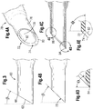
- FIGS 1-2C illustrate an IOL cartridge 20 of the prior art which includes a main body 22 extending longitudinally from a proximal opening 24 to a distal end 26.
- a pair of webs project transversely outward from opposite sides of the main body 22 and terminate in a generally vertically-oriented finger grip 30a, 30b.
- the main body 22 of the cartridge 20 defines a gradually narrowing lumen or hollow interior 32 extending longitudinally from the proximal opening 24 to a distal opening 34 ( Figure 2B ) at the distal end 26.
- FIG 1 illustrates an IOL held by tongs or forceps 50.
- This type of IOL includes a central disc-shaped optic 52, a leading haptic 54, and a trailing haptic 56.
- the optic 52 has opposed convex faces, although the present invention is not limited to cartridges for any particular type of IOL.
- the haptics 54, 56 are shown as thin arcuate members extending outward from opposite edges of the optic 52, and generally in the plane of the optic.
- the haptics 54, 56 curve in the same direction, in this case a counter-clockwise direction looking down on the IOL.
- Figure 2B shows the gradually narrowing lumen 32 from the proximal to the distal end of the cartridge 20, and the general shape of the IOL as it progresses through the main body 22.
- the cartridge 20, as with other such cartridges provides a gradually narrowing lumen 32 that folds or otherwise compresses the IOL into a small profile so that it may be expelled through the distal opening 34 at the distal end 26 and through an incision into the eye.
- Intraocular lenses are inserted into the empty capsular bag left after removing the natural lens from the eye, typically due to opacification from conditions such as glaucoma. Folding the IOL through the cartridge enables a smaller incision to be used, which helps reduce trauma during the operation and recovery.
- the shape of the distal end 26 facilitates introduction of the IOL into the eye and into the capsular bag. More particularly, the distal end 26 defines the termination of the generally tubular main body 22 and features a planar bevel angle ⁇ that results in a pointed leading tip 36 diametrically opposed to a trailing heel 38, such as seen in Figure 2C . Due to the planar bevel, the side portions of the distal end 26 extend in half-ovals between the leading tip 36 and a trailing heel 38.
- the pointed leading tip 36 helps the surgeon open up the incision and extend the distal end 26 into the eye and into the capsular bag, while the relief provided by the bevel angle ⁇ allows the IOL to emerge more gradually from the tip than if the tube was cut off straight, or perpendicular to the central axis.
- the end 26 may be rotated about its axis to allow the surgeon to reposition the heel 38 and thus "aim" the cartridge tip so that the IOL is expelled properly into the capsular bag.
- the planar beveled end 26 as shown typically has a bevel angle ⁇ of about 55° which is conventional in the art and provides adequate level of control for the surgeon.
- bevel angles discussed herein refer to the angle (if there is a single angle) taken from a vertical plane (perpendicular to the central axis of the tubular main body 22) to the distal end 26, indicated in Figure 2C . Consequently, a 0° bevel angle is one which is perpendicular to the central axis, or completely blunt and not beveled at all, and thus does not exist as it does not work. Conversely, the distal end becomes increasingly sharp at higher bevel angles, and angles above 45° are impractically long and do not exist either. Known bevels are between 40-55°.
- planar bevel refers to a distal end 26 that defines a forward-looking distal face that lies exclusively in the plane of the bevel angle, or is flush with the bevel.
- the distal face of the distal end 26 is that surface formed by the thickness of the distal end that extends between the outer 40 and inner 42 tubular walls of the cartridge 20 ( Figure 2C ).
- the entire distal face of the distal end 26 across the wall thickness of the cartridge 20 thus lies flush in a common plane along the bevel angle. This can also be termed a flush distal face because it lies flush within the contour of the distal end as seen from the side ( Figure 2C ).
- the trailing heel 38 of the distal end 26 forms the same sharp angle at the inside wall 42.
- the sharp inner corner angle of the heel 38 sometimes causes cuts or scratches on the expanding IOL, which are sometimes referred to as chatter marks.
- the outward pressure imparted by the passing IOL sometimes creates splits in the cartridge material. That is, the sharp angle at the heel 38 presents an area of concentrated stress in the material which can sometimes split, potentially leading to loss of control of the delicate placement process.
- advances in the field of IOL implantation are driving the diameter of the cartridge distal tips ever smaller, which further reduces the strength of the distal tip. At some point, the strength limit of the distal tip is reached which limits its minimum size.
- the smallest distal tips having a planar bevel are 1.6 mm in diameter, with a wall thickness of .0016 mm.
- One solution shown in Figure 3 involves a cartridge 60 having a distal end 62 with a planar bevel having a much shallower bevel angle ⁇ , such as approximately 30°, or less. More particularly, the bevel angle ⁇ is preferably between about 20-30°.
- the distal face at the heel 66 of the distal end 62 also forms a shallower inner corner angle at the inside wall, thus reducing the potentially damaging sharp edge and also the stress concentration at that point. More specifically, for bevel angles ⁇ between 20-30°, the distal face forms an inner corner with a wall of the lumen at the trailing heel 66 that is between 60-70
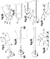
- IOL cartridge 70 is seen in Figures 4A-4C , and includes a distal end 72 that forms a straight bevel angle ⁇ of about 65°, much like those in the prior art.
- An outer edge 80 of the distal face 74 lies in and defines the plane of the bevel angle ⁇ , preferably about 40-45°. Since the bevel as seen from the side as in Figure 4B is straight, this configuration can be denoted a straight bevel.
- a planar bevel as described above is a subset of straight bevels.
- the distal face 74 is angled or chamfered such that not all of it lies in the plane of the bevel angle ⁇ .
- an inner edge 82 of the distal face 74 does not lie in the plane of the bevel angle
- Another way to describe the distal face 74 is that it does not lie flush within the bevel plane.
- the distal end 72 has a variable chamfer around its circumference.
- the angle of the distal face 74 (face angle) changes from an angle ⁇ that is greater than the bevel angle (i.e., sharper) at a leading tip 84 (See Figure 4D ) to one that is more blunt than the bevel angle at a trailing heel 86.
- the leading tip 84 is diametrically opposed around the distal end 72 from the trailing heel 86.
- the face angle around the distal end 72 is that angle the distal face 74 makes with a plane perpendicular to the tubular axis as seen in any longitudinal section through the distal end (such as seen in Figures 4C-4E with a vertical longitudinal section).
- the face angle at the heel 86 is 0°, as seen in Figure 4E . Consequently, the inner edge 82 of the distal face 74 at the trailing heel 86 forms an inner corner angle ⁇ of about 90° at the intersection with the cartridge inner wall 78. This removes the sharp edge at the heel 86 which reduces the chance of damaging the IOL as it expulses from the distal end 72.
- Another way to state this solution is that the inner corner angle ⁇ at the trailing heel 86 is decoupled from the bevel angle ⁇ , which is not the case with a planar bevel.
- the cartridge 90 is configured differently than that described above, though it is still adapted to receive an IOL and then mate with an inserter (not shown) for injection into an eye.
- the majority of the cartridge 90 is not particularly relevant to the disclosure of the present invention, and thus is shown in phantom, it typically includes a proximal body 92 having a proximal opening 94 in the form of a channel for receiving an IOL.
- a tubular nose 96 aligned with the opening 94 extends distally from the body 92 and terminates at a distal end 100.
- the distal end 100 defines an opening that is smaller than the IOL such that as the IOL progresses distally from the proximal opening 94 is folded or otherwise compressed into a rolled configuration.
- the distal end 100 is shown in greater detail in Figures 6A-6F , and defines a straight bevel angle ⁇ as seen in Figure 6D , preferably about 40-45°.
- an outer edge 102 of a distal face 104 lies in and defines the bevel plane.
- the distal face 104 extends between an outer cartridge wall 106 and an inner cartridge wall 108 that defines the tube lumen.
- the distal face 104 has a chamfer angle that does not lie flush in the bevel plane.
- an inner edge 110 of the distal face 104 is recessed into the lumen.
- the distal face 104 makes a chamfer angle ⁇ that is larger than the bevel angle.
- the distal face 104 makes a chamfer angle ⁇ that is also larger than the bevel angle, and in the opposite direction. It should be noted that a chamfer at the trailing heel 114 which forms an angle opposite to the bevel angle and is greater than 0° (such as in Figure 4E ) results in an obtuse inner corner angle ⁇ .
- the angle ⁇ may be equal to the angle ⁇ or one may be larger than the other.
- the distal face chamfer angle ⁇ at the leading tip 112 is equal to the distal face chamfer angle ⁇ at the trailing heel 114, and they both are between about 70-80°.
- the trailing chamfer angle ⁇ may be as small as 0°, such as in the embodiment of Figures 4A-4E , it is desirably greater than 30° to result in an obtuse inner corner angle.
- Both the leading tip 112 and trailing heel 114 therefore define sharp points at their outer edges 102, but relatively shallow (obtuse) inner corner angles at their inner edges 110. These shallow corner angles serve two purposes: first, there is little chance of the inner edges 110 causing damage to the passing IOL, and second, the material at the inner edges 110 experiences no stress concentration which might lead to tearing.
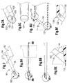
- a still further alternative distal end 120 for an IOL cartridge 90 is shown in Figures 7-8 .
- the IOL cartridge 90 may be similar to that shown in Figure 5 , or may be another configuration such as that shown in Figure 1 .
- the majority of the cartridge 90 is not particularly relevant to the disclosure of the present invention, and thus is shown in phantom.
- the distal end 120 is shown in greater detail in Figures 7A and 8A-8F , and defines a straight bevel angle ⁇ as seen in Figure 8D , preferably about 40-45°.
- an outer edge 122 of a distal face 124 lies in and defines the bevel plane.
- the distal face 124 extends between an outer cartridge wall 126 and an inner cartridge wall 128 that defines the tube lumen.
- the distal face 124 has a chamfer angle that does not lie flush in the bevel plane.
- the distal end 120 is similar to the distal end 100 of Figures 5-6 , though one difference is that the extension of the tubular nose 96 of the cartridge 90 becomes gradually more elliptical, or more like a rounded rectangle. This configuration may accommodate the IOLs somewhat better as the optic portion assumes a more flattened as opposed to rolled tubular shape.
- an inner edge 130 of the distal face 124 is recessed into the lumen.
- the distal face 124 makes a chamfer angle ⁇ that is larger than the bevel angle.
- the distal face 124 makes a chamfer angle ⁇ that is opposite the bevel angle.
- the angle ⁇ may be equal to the angle ⁇ or one may be larger than the other.
- the distal face chamfer angle ⁇ at the leading tip 132 is greater than the distal face chamfer angle ⁇ at the trailing heel 134.
- leading chamfer angle ⁇ is between about 70-80°, while the trailing chamfer angle ⁇ is between about 60-70°.
- trailing chamfer angle ⁇ may be as small as 0°, such as in the embodiment of Figures 4A-4E , though it is desirably greater than 30° to result in an obtuse inner corner angle.
- Both the leading tip 132 and trailing heel 134 therefore define sharp points at their outer edges 122, but relatively shallow (obtuse) inner corner angles at their inner edges 130. These shallow corner angles reduce the chance of the inner edges 130 causing damage to the passing IOL, and reduce the stress concentration in the distal end 120 which might lead to tearing.
- Figure 8F also shows a somewhat different trailing heel 134 than in earlier embodiments.
- the distal face 124 at that point does not intersect the outer cartridge wall 126, but instead terminates at its outer edge 122 a short way down the straight bevel.
- Another way to state this is that the distal face 124 at the trailing heel 134 does not pass through the intersection of the bevel with the outer cartridge wall 126. This results in a short length of added material at the sharp point of the outer cartridge wall 126 which helps strengthen the wall and avoids tearing during expulsion of the compressed IOL.
- a still further alternative distal end 140 for an IOL cartridge 90 is shown in Figures 9-10 .
- the IOL cartridge 90 may be similar to that shown in Figure 5 , or may be another configuration such as that shown in Figure 1 .
- the distal end 140 is shown in greater detail in Figures 9A and 10C-10F , and once again defines a straight bevel angle ⁇ as seen in Figure 10D , preferably about 40-45°.
- An outer edge 142 of a distal face lies in and defines the bevel plane.
- the distal face extends between an outer cartridge wall 144 and an inner cartridge wall 146 that defines the tube lumen.
- the distal face does not lie flush in the bevel plane, but in this configuration there is no single chamfer but a more rounded face from the trailing heel 148 to the leading tip 150 and in between.
- the distal face extends between an outer edge 152 and an inner edge 154 and forms a rounded face 156.
- the distal face forms a rounded face 158.
- These rounded faces 156, 158 may have similar curvatures, though due to their different geometries the rounded face 158 at the trailing heel 148 extends around a greater arc than the face 156 at the leading tip 150.
- the result is a smooth surface around the distal end 140 of the cartridge 90, which eliminates any sharp edges and corresponding danger of scratching the IOL. It should be noted that a rounded distal face is not flush with the particular bevel, much like the earlier-described chamfers.
- a slightly different cartridge distal end 170 (not forming part of the invention) is shown.
- the distal end 170 is pointed with a leading tip 172 and a trailing heel 174.
- the distal end 170 has a curved bevel, with a relatively shallow curvature 176 adjacent the leading tip 172 gradually increasing to a step 178 adjacent the trailing heel 174.
- the angle of the curved bevel at the trailing heel 174 is about 0°.
- the bevel angle adjacent the leading tip 172 is greater than the bevel angle adjacent the trailing heel 174.
- curved bevel is not strictly a bevel, but the terminology will be used to indicate its proximity to a straight bevel.
- a beveled end refers to both straight and curved bevels, wherein both include a leading tip opposed to a trailing heel.
- a preferred configuration provides symmetry about a central plane through a diametrically opposed leading tip 172 and trailing heel 174, though a symmetric configurations are contemplated.
- distal face is flush with the curved bevel, meaning that the entire distal face lies in the curvature of the distal end 170 as seen from the side in Figure 11A . Consequently, as seen in Figure 11B , the distal face has a 90° inner corner angle 180 at the trailing heel 174, much like the embodiment of Figures 4A-4C . Once more, this reduces the potential for damaging IOL as it passes out of the lumen of the cartridge end 170.
- the distal face need not lie flush within the curvature of the distal end 170, and may be chamfered as described in several embodiments above.
- Figures 12A-12B illustrate a still further cartridge distal end 190 (not forming part of the invention) having a curved bevel.
- the curved bevel extends between a leading tip 192 and a trailing heel 194.
- the distal face lies flush with the curvature of the curved bevel.
- the bevel angle adjacent the leading tip 192 is greater than the bevel angle adjacent the trailing heel 194.
- the curvature is modified, with a shallow arc 196 adjacent the leading tip 192 which transitions into a less pronounced step 198 adjacent to the trailing heel 194. This configuration results in a slightly acute inner corner 200 at the trailing heel 194, as seen in Figure 12B .
- the inner corner 200 will be sufficiently blunt to avoid damage to the passing IOL.
- the distal face forms an inner corner 200 with a wall of the lumen at the trailing heel 194 having an angle that is ⁇ 60°.
- several embodiments above described inner corner angles of 90° and greater, and the lower limit of 60° is considered to be the sharpest inner corner angle that can be utilized without creating significant risk of scratching the IOL.
- the cartridge distal end 220 shown in Figures 13A-13B includes a partial planar bevel. More particularly, a majority of the distal face 222 lies flush with the plane of the bevel, which may be 40-45°, but is interrupted by a scoop or cutout 224 at the trailing heel 226. In other words, as seen in Figure 13B , the distal face 222 extends from a leading tip 228 up into proximity with the trailing heel 226, but is interrupted by the cutout 224.
- the cutout 224 extends a short distance down around the distal end 220, such as about 30° symmetrically from a central vertical plane.
- the cutout 224 may be formed at an angle perpendicular to the central axis of the tubular cartridge distal end 220, as shown, or may be slightly angled toward the bevel (up to about 30°) or even chamfered in an opposite direction to the bevel. The result is an inner corner angle that is less likely to scratch or otherwise damage the passing IOL. Moreover, the remaining portion of the distal end can remain as a planar bevel, which maintains ease of cartridge tip insertion into the wound and is proven effective in delivering the IOL. In the illustrated embodiment the inner corner angle is 90°.
- the cutout 224 can be viewed as an abbreviated chamfer in contrast to the variably chamfered embodiments described above.
- the various solutions for cartridge distal ends provided herein permit the distal ends to have diameters down to about 1.4 mm, with a wall thickness of about 0.014 mm.
- Materials used for the IOL cartridges described herein include polypropylene, polycarbonate, polyurethane or other appropriate thermoplastics.
- the various shapes for the distal ends can be formed by molding or laser cutting. In particular, the variable chamfer geometries are especially well-suited to injection molding.
Landscapes
- Health & Medical Sciences (AREA)
- Ophthalmology & Optometry (AREA)
- Cardiology (AREA)
- Oral & Maxillofacial Surgery (AREA)
- Transplantation (AREA)
- Engineering & Computer Science (AREA)
- Biomedical Technology (AREA)
- Heart & Thoracic Surgery (AREA)
- Vascular Medicine (AREA)
- Life Sciences & Earth Sciences (AREA)
- Animal Behavior & Ethology (AREA)
- General Health & Medical Sciences (AREA)
- Public Health (AREA)
- Veterinary Medicine (AREA)
- Prostheses (AREA)
Claims (8)
- Kartusche (20, 60, 70, 90) zur Aufnahme und Abgabe einer Intraokularlinse an das Innenauge, umfassend:einen Hauptkörper (22), der sich in Längsrichtung von einer proximalen Öffnung (24) zur Aufnahme der Intraokularlinse zu einem distalen Ende (26, 62) erstreckt, undein Lumen (32), das sich von der proximalen Öffnung (24) zum distalen Ende (26, 62) erstreckt, das eine distale Öffnung (34) definiert, die kleiner als die Intraokularlinse ist,wobei das distale Ende (26, 62) in der Seitenansicht gesehen abgeschrägt ist und eine vordere Spitze (36, 84, 112, 132, 150, 172, 192, 228) unter und gegenüber einem hinteren Ende (38, 66, 86, 114, 134, 148, 174, 194, 226) aufweist,wobei das distale Ende (26, 62) ferner eine distale Fläche (74, 104, 124, 222) zwischen einer Außenseite und dem Lumen definiert,dadurch gekennzeichnet, dassdie distale Fläche (74, 104, 124, 222) eine innere Ecke mit einer Wand des Lumens (32) am hinteren Ende (38, 66, 86, 114, 134, 148, 174, 194, 226) mit einem Winkel φ ≥ 60° bildet.
- Kartusche (20, 60, 70, 90) nach Anspruch 1, wobei die distale Fläche (74, 104, 124, 222) eine innere Ecke mit einer Wand des Lumens am hinteren Ende (38, 66, 86, 114, 134, 148, 174, 194, 226) mit einem Winkel φ ≥ 90° bildet.
- Kartusche (20, 60, 70, 90) nach Anspruch 1, wobei das abgeschrägte distale Ende (26, 62) eine gerade Abschrägung definiert.
- Kartusche (20, 60, 70, 90) nach Anspruch 1, wobei das abgeschrägte distale Ende (26, 62) eine gebogene Abschrägung definiert.
- Kartusche (20, 60, 70, 90) nach Anspruch 4, wobei ein Neigungswinkel neben der vorderen Spitze (36, 84, 112, 132, 150, 172, 192, 228) größer als ein Neigungswinkel neben dem hinteren Ende (38, 66, 86, 114, 134, 148, 174, 194, 226) ist.
- Kartusche (20, 60, 70, 90) nach Anspruch 1, wobei die distale Fläche (74, 104, 124, 222) eine Abfasung aufweist, die in einer Ausschnittregion gebildet ist, die mit dem abgeschrägten distalen Ende (26, 62) nicht bündig ist.
- Kartusche (20, 60, 70, 90) nach Anspruch 1, wobei die distale Fläche (74, 104, 124, 222) um ihren gesamten Umfang nicht mit dem abgeschrägten distalen Ende (26, 62) bündig ist.
- Kartusche (90) nach Anspruch 1, wobei die distale Fläche (104) an der vorderen Spitze (112) einen Fasenwinkel θ an der distalen Spitze (112) bildet, der größer als ein Neigungswinkel ist, und die distale Fläche (104) am hinteren Ende (114) einen Fasenwinkel α bildet, der ebenfalls größer als der Neigungswinkel und in der entgegengesetzten Richtung ist, so dass er in einem stumpfen inneren Eckwinkel φ resultiert.
Applications Claiming Priority (2)
| Application Number | Priority Date | Filing Date | Title |
|---|---|---|---|
| US201361773496P | 2013-03-06 | 2013-03-06 | |
| PCT/US2014/019987 WO2014137925A1 (en) | 2013-03-06 | 2014-03-03 | Atraumatic iol insertion cartridge opening |
Publications (2)
| Publication Number | Publication Date |
|---|---|
| EP2964150A1 EP2964150A1 (de) | 2016-01-13 |
| EP2964150B1 true EP2964150B1 (de) | 2017-04-19 |
Family
ID=50290319
Family Applications (1)
| Application Number | Title | Priority Date | Filing Date |
|---|---|---|---|
| EP14711109.0A Active EP2964150B1 (de) | 2013-03-06 | 2014-03-03 | Atraumatische iol-einsatzkartuschenöffnung |
Country Status (5)
| Country | Link |
|---|---|
| US (4) | US10265164B2 (de) |
| EP (1) | EP2964150B1 (de) |
| AU (1) | AU2014226148B2 (de) |
| CA (1) | CA2875869C (de) |
| WO (1) | WO2014137925A1 (de) |
Families Citing this family (3)
| Publication number | Priority date | Publication date | Assignee | Title |
|---|---|---|---|---|
| EP2964150B1 (de) * | 2013-03-06 | 2017-04-19 | Abbott Medical Optics Inc. | Atraumatische iol-einsatzkartuschenöffnung |
| DE102020109867B4 (de) * | 2020-04-08 | 2023-08-31 | Carl Zeiss Meditec Ag | Intraokularlinsen-Injektor mit spezifischer Einstechspitze einer Hohlnadel |
| DE102020125130B3 (de) * | 2020-09-25 | 2022-01-13 | Carl Zeiss Meditec Ag | Injektor |
Family Cites Families (30)
| Publication number | Priority date | Publication date | Assignee | Title |
|---|---|---|---|---|
| BE720694A (de) * | 1968-09-11 | 1969-02-17 | ||
| US4490139A (en) * | 1983-01-28 | 1984-12-25 | Eli Lilly And Company | Implant needle and method |
| US4681102A (en) | 1985-09-11 | 1987-07-21 | Bartell Michael T | Apparatus and method for insertion of an intra-ocular lens |
| US4919130A (en) * | 1986-11-07 | 1990-04-24 | Nestle S.A. | Tool for inserting compressible intraocular lenses into the eye and method |
| US5928245A (en) * | 1992-09-30 | 1999-07-27 | Staar Surgical Company, Inc. | Deformable intraocular lens injecting apparatus with transverse hinged lens cartridge |
| US6056757A (en) * | 1992-09-30 | 2000-05-02 | Staar Surgical Company, Inc. | Implantation device with deformable nozzle tip for implanting a deformable intraocular lens |
| US6506195B2 (en) * | 1992-09-30 | 2003-01-14 | Staar Surgical Company, Inc. | Deformable intraocular lens insertion system |
| US5653715A (en) * | 1993-03-09 | 1997-08-05 | Chiron Vision Corporation | Apparatus for preparing an intraocular lens for insertion |
| US5702402A (en) | 1994-04-29 | 1997-12-30 | Allergal | Method and apparatus for folding of intraocular lens |
| US5575780A (en) * | 1995-04-28 | 1996-11-19 | Saito; Yoshikuni | Medical hollow needle and a method of producing thereof |
| US5536259A (en) * | 1995-07-28 | 1996-07-16 | Medisystems Technology Corp | Hypodermic cannula |
| US5788679A (en) * | 1996-06-26 | 1998-08-04 | Gravlee, Jr.; Joseph F. | Phacoemulsification needle |
| US5876406A (en) * | 1996-08-02 | 1999-03-02 | Staar Surgical Company, Inc. | Deformable intraocular lens injecting apparatus with transverse hinged lens cartridge |
| US5810834A (en) * | 1996-10-07 | 1998-09-22 | Chiron Vision Corporation | Tip formation for inserting a flexible membrane into an eye |
| KR100213463B1 (ko) * | 1997-03-31 | 1999-08-02 | 신명철 | 생체 조직 채취용 바늘과 그 제조 방법 및 그 조작 기구 |
| US7063681B1 (en) * | 1998-04-23 | 2006-06-20 | Alza Corporation | Trocar for inserting implants |
| US6447520B1 (en) * | 2001-03-19 | 2002-09-10 | Advanced Medical Optics, Inc. | IOL insertion apparatus with IOL engagement structure and method for using same |
| US6248111B1 (en) * | 1999-08-06 | 2001-06-19 | Allergan Sales, Inc. | IOL insertion apparatus and methods for using same |
| GB0011507D0 (en) * | 2000-05-13 | 2000-06-28 | Duckworth & Kent Ltd | Ophthalmic lens injectors |
| WO2006070628A1 (ja) * | 2004-12-27 | 2006-07-06 | Hoya Corporation | 眼内レンズ移植装置 |
| US20060167466A1 (en) * | 2005-01-21 | 2006-07-27 | Vaclav Dusek | Intraocular lens inserter system components |
| CA2599455A1 (en) * | 2005-01-28 | 2006-08-03 | The General Hospital Corporation | Biopsy needle |
| US7670299B2 (en) * | 2006-03-07 | 2010-03-02 | Ethincon Endo-Surgery, Inc. | Device for minimally invasive internal tissue removal |
| US20080312661A1 (en) | 2007-06-12 | 2008-12-18 | Downer David A | Lens Injector Lumen Tip for Wound Assisted Delivery |
| JP5470753B2 (ja) * | 2008-06-17 | 2014-04-16 | Hoya株式会社 | 眼内レンズ挿入器具 |
| GB201002946D0 (en) * | 2010-02-22 | 2010-04-07 | Rayner Intraocular Lenses Ltd | Device for inserting an intraocular lens into an eye |
| JP5658992B2 (ja) * | 2010-12-14 | 2015-01-28 | 興和株式会社 | 眼内レンズの挿入器具 |
| US9155615B2 (en) * | 2012-11-09 | 2015-10-13 | Bausch & Lomb Incorporated | Hingeless cartridge for use with an intraocular lens injector providing haptic control |
| EP2964150B1 (de) * | 2013-03-06 | 2017-04-19 | Abbott Medical Optics Inc. | Atraumatische iol-einsatzkartuschenöffnung |
| US10806901B2 (en) * | 2015-10-28 | 2020-10-20 | Becton, Dickinson And Company | Catheter adapter with distal inner diameter curvature providing kink resistance |
-
2014
- 2014-03-03 EP EP14711109.0A patent/EP2964150B1/de active Active
- 2014-03-03 CA CA2875869A patent/CA2875869C/en active Active
- 2014-03-03 US US14/195,622 patent/US10265164B2/en active Active
- 2014-03-03 AU AU2014226148A patent/AU2014226148B2/en not_active Ceased
- 2014-03-03 WO PCT/US2014/019987 patent/WO2014137925A1/en not_active Ceased
-
2019
- 2019-01-24 US US16/257,010 patent/US11000368B2/en active Active
-
2021
- 2021-04-19 US US17/234,685 patent/US11717396B2/en active Active
-
2023
- 2023-03-05 US US18/178,509 patent/US12053368B2/en active Active
Non-Patent Citations (1)
| Title |
|---|
| None * |
Also Published As
| Publication number | Publication date |
|---|---|
| CA2875869A1 (en) | 2014-09-12 |
| CA2875869C (en) | 2021-06-29 |
| AU2014226148B2 (en) | 2018-02-15 |
| WO2014137925A1 (en) | 2014-09-12 |
| US12053368B2 (en) | 2024-08-06 |
| US20230200979A1 (en) | 2023-06-29 |
| US20190151080A1 (en) | 2019-05-23 |
| EP2964150A1 (de) | 2016-01-13 |
| US11000368B2 (en) | 2021-05-11 |
| US20140257316A1 (en) | 2014-09-11 |
| US20210236272A1 (en) | 2021-08-05 |
| US11717396B2 (en) | 2023-08-08 |
| US10265164B2 (en) | 2019-04-23 |
| AU2014226148A1 (en) | 2014-11-06 |
Similar Documents
| Publication | Publication Date | Title |
|---|---|---|
| US12053368B2 (en) | Atraumatic IOL insertion cartridge opening | |
| JP4685897B2 (ja) | ウーン・アシステッド送達用のレンズ注入器用管腔チップ | |
| US7033366B2 (en) | Stepped IOL insertion cartridge inserting an intraocular lens in an eye | |
| US6733507B2 (en) | Intraocular lens insertion apparatus | |
| US5258002A (en) | Dual tapered surgical knife | |
| EP0723429B1 (de) | Intraokulares linsen-einführungssystem | |
| CA2722953C (en) | Back loaded iol insertion cartridge | |
| EP0980230B1 (de) | Verbesserter kolben | |
| KR101264267B1 (ko) | 렌즈 전달 시스템 카트리지 | |
| US20060264971A1 (en) | Intraocular lens injection nozzle | |
| US9155615B2 (en) | Hingeless cartridge for use with an intraocular lens injector providing haptic control | |
| EP1262154A1 (de) | Instrument zum Einführen einer Intraokularlinse | |
| JP2008259833A (ja) | レンズ送達装置用カートリッジとその製造方法 | |
| JP2025026462A (ja) | 眼科用ブレード及び器具並びにその使用方法 | |
| KR102390116B1 (ko) | 쉽고 안전한 방법으로 안압을 내릴 수 있는 안질환용 임플란트 장치 | |
| US11950998B2 (en) | Intraocular lens insertion device | |
| EP3787719B1 (de) | Intraokularlinseninjektor | |
| AU2020333735B2 (en) | Ophthalmic blades and instruments and methods of use thereof | |
| AU717897B2 (en) | Intraocular lens insertion system |
Legal Events
| Date | Code | Title | Description |
|---|---|---|---|
| PUAI | Public reference made under article 153(3) epc to a published international application that has entered the european phase |
Free format text: ORIGINAL CODE: 0009012 |
|
| 17P | Request for examination filed |
Effective date: 20150929 |
|
| AK | Designated contracting states |
Kind code of ref document: A1 Designated state(s): AL AT BE BG CH CY CZ DE DK EE ES FI FR GB GR HR HU IE IS IT LI LT LU LV MC MK MT NL NO PL PT RO RS SE SI SK SM TR |
|
| AX | Request for extension of the european patent |
Extension state: BA ME |
|
| DAX | Request for extension of the european patent (deleted) | ||
| GRAP | Despatch of communication of intention to grant a patent |
Free format text: ORIGINAL CODE: EPIDOSNIGR1 |
|
| INTG | Intention to grant announced |
Effective date: 20161129 |
|
| GRAS | Grant fee paid |
Free format text: ORIGINAL CODE: EPIDOSNIGR3 |
|
| GRAA | (expected) grant |
Free format text: ORIGINAL CODE: 0009210 |
|
| AK | Designated contracting states |
Kind code of ref document: B1 Designated state(s): AL AT BE BG CH CY CZ DE DK EE ES FI FR GB GR HR HU IE IS IT LI LT LU LV MC MK MT NL NO PL PT RO RS SE SI SK SM TR |
|
| REG | Reference to a national code |
Ref country code: GB Ref legal event code: FG4D |
|
| REG | Reference to a national code |
Ref country code: CH Ref legal event code: EP |
|
| REG | Reference to a national code |
Ref country code: AT Ref legal event code: REF Ref document number: 885197 Country of ref document: AT Kind code of ref document: T Effective date: 20170515 |
|
| REG | Reference to a national code |
Ref country code: IE Ref legal event code: FG4D |
|
| REG | Reference to a national code |
Ref country code: DE Ref legal event code: R096 Ref document number: 602014008774 Country of ref document: DE |
|
| REG | Reference to a national code |
Ref country code: NL Ref legal event code: FP |
|
| REG | Reference to a national code |
Ref country code: LT Ref legal event code: MG4D |
|
| REG | Reference to a national code |
Ref country code: AT Ref legal event code: MK05 Ref document number: 885197 Country of ref document: AT Kind code of ref document: T Effective date: 20170419 |
|
| PG25 | Lapsed in a contracting state [announced via postgrant information from national office to epo] |
Ref country code: GR Free format text: LAPSE BECAUSE OF FAILURE TO SUBMIT A TRANSLATION OF THE DESCRIPTION OR TO PAY THE FEE WITHIN THE PRESCRIBED TIME-LIMIT Effective date: 20170720 Ref country code: LT Free format text: LAPSE BECAUSE OF FAILURE TO SUBMIT A TRANSLATION OF THE DESCRIPTION OR TO PAY THE FEE WITHIN THE PRESCRIBED TIME-LIMIT Effective date: 20170419 Ref country code: FI Free format text: LAPSE BECAUSE OF FAILURE TO SUBMIT A TRANSLATION OF THE DESCRIPTION OR TO PAY THE FEE WITHIN THE PRESCRIBED TIME-LIMIT Effective date: 20170419 Ref country code: NO Free format text: LAPSE BECAUSE OF FAILURE TO SUBMIT A TRANSLATION OF THE DESCRIPTION OR TO PAY THE FEE WITHIN THE PRESCRIBED TIME-LIMIT Effective date: 20170719 Ref country code: AT Free format text: LAPSE BECAUSE OF FAILURE TO SUBMIT A TRANSLATION OF THE DESCRIPTION OR TO PAY THE FEE WITHIN THE PRESCRIBED TIME-LIMIT Effective date: 20170419 Ref country code: HR Free format text: LAPSE BECAUSE OF FAILURE TO SUBMIT A TRANSLATION OF THE DESCRIPTION OR TO PAY THE FEE WITHIN THE PRESCRIBED TIME-LIMIT Effective date: 20170419 Ref country code: ES Free format text: LAPSE BECAUSE OF FAILURE TO SUBMIT A TRANSLATION OF THE DESCRIPTION OR TO PAY THE FEE WITHIN THE PRESCRIBED TIME-LIMIT Effective date: 20170419 |
|
| PG25 | Lapsed in a contracting state [announced via postgrant information from national office to epo] |
Ref country code: SE Free format text: LAPSE BECAUSE OF FAILURE TO SUBMIT A TRANSLATION OF THE DESCRIPTION OR TO PAY THE FEE WITHIN THE PRESCRIBED TIME-LIMIT Effective date: 20170419 Ref country code: RS Free format text: LAPSE BECAUSE OF FAILURE TO SUBMIT A TRANSLATION OF THE DESCRIPTION OR TO PAY THE FEE WITHIN THE PRESCRIBED TIME-LIMIT Effective date: 20170419 Ref country code: LV Free format text: LAPSE BECAUSE OF FAILURE TO SUBMIT A TRANSLATION OF THE DESCRIPTION OR TO PAY THE FEE WITHIN THE PRESCRIBED TIME-LIMIT Effective date: 20170419 Ref country code: PL Free format text: LAPSE BECAUSE OF FAILURE TO SUBMIT A TRANSLATION OF THE DESCRIPTION OR TO PAY THE FEE WITHIN THE PRESCRIBED TIME-LIMIT Effective date: 20170419 Ref country code: IS Free format text: LAPSE BECAUSE OF FAILURE TO SUBMIT A TRANSLATION OF THE DESCRIPTION OR TO PAY THE FEE WITHIN THE PRESCRIBED TIME-LIMIT Effective date: 20170819 Ref country code: BG Free format text: LAPSE BECAUSE OF FAILURE TO SUBMIT A TRANSLATION OF THE DESCRIPTION OR TO PAY THE FEE WITHIN THE PRESCRIBED TIME-LIMIT Effective date: 20170719 |
|
| REG | Reference to a national code |
Ref country code: DE Ref legal event code: R097 Ref document number: 602014008774 Country of ref document: DE |
|
| PG25 | Lapsed in a contracting state [announced via postgrant information from national office to epo] |
Ref country code: SK Free format text: LAPSE BECAUSE OF FAILURE TO SUBMIT A TRANSLATION OF THE DESCRIPTION OR TO PAY THE FEE WITHIN THE PRESCRIBED TIME-LIMIT Effective date: 20170419 Ref country code: CZ Free format text: LAPSE BECAUSE OF FAILURE TO SUBMIT A TRANSLATION OF THE DESCRIPTION OR TO PAY THE FEE WITHIN THE PRESCRIBED TIME-LIMIT Effective date: 20170419 Ref country code: EE Free format text: LAPSE BECAUSE OF FAILURE TO SUBMIT A TRANSLATION OF THE DESCRIPTION OR TO PAY THE FEE WITHIN THE PRESCRIBED TIME-LIMIT Effective date: 20170419 Ref country code: DK Free format text: LAPSE BECAUSE OF FAILURE TO SUBMIT A TRANSLATION OF THE DESCRIPTION OR TO PAY THE FEE WITHIN THE PRESCRIBED TIME-LIMIT Effective date: 20170419 Ref country code: RO Free format text: LAPSE BECAUSE OF FAILURE TO SUBMIT A TRANSLATION OF THE DESCRIPTION OR TO PAY THE FEE WITHIN THE PRESCRIBED TIME-LIMIT Effective date: 20170419 |
|
| REG | Reference to a national code |
Ref country code: CH Ref legal event code: NV Representative=s name: E. BLUM AND CO. AG PATENT- UND MARKENANWAELTE , CH |
|
| PLBE | No opposition filed within time limit |
Free format text: ORIGINAL CODE: 0009261 |
|
| REG | Reference to a national code |
Ref country code: FR Ref legal event code: PLFP Year of fee payment: 5 |
|
| STAA | Information on the status of an ep patent application or granted ep patent |
Free format text: STATUS: NO OPPOSITION FILED WITHIN TIME LIMIT |
|
| PG25 | Lapsed in a contracting state [announced via postgrant information from national office to epo] |
Ref country code: IT Free format text: LAPSE BECAUSE OF FAILURE TO SUBMIT A TRANSLATION OF THE DESCRIPTION OR TO PAY THE FEE WITHIN THE PRESCRIBED TIME-LIMIT Effective date: 20170419 Ref country code: SM Free format text: LAPSE BECAUSE OF FAILURE TO SUBMIT A TRANSLATION OF THE DESCRIPTION OR TO PAY THE FEE WITHIN THE PRESCRIBED TIME-LIMIT Effective date: 20170419 |
|
| 26N | No opposition filed |
Effective date: 20180122 |
|
| PG25 | Lapsed in a contracting state [announced via postgrant information from national office to epo] |
Ref country code: SI Free format text: LAPSE BECAUSE OF FAILURE TO SUBMIT A TRANSLATION OF THE DESCRIPTION OR TO PAY THE FEE WITHIN THE PRESCRIBED TIME-LIMIT Effective date: 20170419 |
|
| PG25 | Lapsed in a contracting state [announced via postgrant information from national office to epo] |
Ref country code: MC Free format text: LAPSE BECAUSE OF FAILURE TO SUBMIT A TRANSLATION OF THE DESCRIPTION OR TO PAY THE FEE WITHIN THE PRESCRIBED TIME-LIMIT Effective date: 20170419 |
|
| REG | Reference to a national code |
Ref country code: CH Ref legal event code: PFA Owner name: JOHNSON AND JOHNSON SURGICAL VISION, INC., US Free format text: FORMER OWNER: ABBOTT MEDICAL OPTICS INC., US |
|
| REG | Reference to a national code |
Ref country code: BE Ref legal event code: MM Effective date: 20180331 |
|
| REG | Reference to a national code |
Ref country code: IE Ref legal event code: MM4A |
|
| PG25 | Lapsed in a contracting state [announced via postgrant information from national office to epo] |
Ref country code: LU Free format text: LAPSE BECAUSE OF NON-PAYMENT OF DUE FEES Effective date: 20180303 |
|
| REG | Reference to a national code |
Ref country code: DE Ref legal event code: R081 Ref document number: 602014008774 Country of ref document: DE Owner name: JOHNSON & JOHNSON SURGICAL VISION, INC., IRVIN, US Free format text: FORMER OWNER: ABBOTT MEDICAL OPTICS INC., SANTA ANA, CALIF., US Ref country code: DE Ref legal event code: R081 Ref document number: 602014008774 Country of ref document: DE Owner name: JOHNSON & JOHNSON SURGICAL VISION, INC. (N. D., US Free format text: FORMER OWNER: ABBOTT MEDICAL OPTICS INC., SANTA ANA, CALIF., US |
|
| REG | Reference to a national code |
Ref country code: NL Ref legal event code: HC Owner name: JOHNSON & JOHNSON SURGICAL VISION, INC.; US Free format text: DETAILS ASSIGNMENT: CHANGE OF OWNER(S), CHANGE OF OWNER(S) NAME; FORMER OWNER NAME: ABBOTT MEDICAL OPTICS INC. Effective date: 20181204 |
|
| PG25 | Lapsed in a contracting state [announced via postgrant information from national office to epo] |
Ref country code: IE Free format text: LAPSE BECAUSE OF NON-PAYMENT OF DUE FEES Effective date: 20180303 |
|
| PG25 | Lapsed in a contracting state [announced via postgrant information from national office to epo] |
Ref country code: BE Free format text: LAPSE BECAUSE OF NON-PAYMENT OF DUE FEES Effective date: 20180331 |
|
| PG25 | Lapsed in a contracting state [announced via postgrant information from national office to epo] |
Ref country code: MT Free format text: LAPSE BECAUSE OF NON-PAYMENT OF DUE FEES Effective date: 20180303 |
|
| PG25 | Lapsed in a contracting state [announced via postgrant information from national office to epo] |
Ref country code: TR Free format text: LAPSE BECAUSE OF FAILURE TO SUBMIT A TRANSLATION OF THE DESCRIPTION OR TO PAY THE FEE WITHIN THE PRESCRIBED TIME-LIMIT Effective date: 20170419 |
|
| PG25 | Lapsed in a contracting state [announced via postgrant information from national office to epo] |
Ref country code: PT Free format text: LAPSE BECAUSE OF FAILURE TO SUBMIT A TRANSLATION OF THE DESCRIPTION OR TO PAY THE FEE WITHIN THE PRESCRIBED TIME-LIMIT Effective date: 20170419 |
|
| PG25 | Lapsed in a contracting state [announced via postgrant information from national office to epo] |
Ref country code: MK Free format text: LAPSE BECAUSE OF NON-PAYMENT OF DUE FEES Effective date: 20170419 Ref country code: HU Free format text: LAPSE BECAUSE OF FAILURE TO SUBMIT A TRANSLATION OF THE DESCRIPTION OR TO PAY THE FEE WITHIN THE PRESCRIBED TIME-LIMIT; INVALID AB INITIO Effective date: 20140303 Ref country code: CY Free format text: LAPSE BECAUSE OF FAILURE TO SUBMIT A TRANSLATION OF THE DESCRIPTION OR TO PAY THE FEE WITHIN THE PRESCRIBED TIME-LIMIT Effective date: 20170419 |
|
| PG25 | Lapsed in a contracting state [announced via postgrant information from national office to epo] |
Ref country code: AL Free format text: LAPSE BECAUSE OF FAILURE TO SUBMIT A TRANSLATION OF THE DESCRIPTION OR TO PAY THE FEE WITHIN THE PRESCRIBED TIME-LIMIT Effective date: 20170419 |
|
| REG | Reference to a national code |
Ref country code: DE Ref legal event code: R081 Ref document number: 602014008774 Country of ref document: DE Owner name: JOHNSON & JOHNSON SURGICAL VISION, INC., IRVIN, US Free format text: FORMER OWNER: JOHNSON & JOHNSON SURGICAL VISION, INC. (N. D. GES. D. STAATES DELAWARE), SANTA ANA, CA, US |
|
| PGFP | Annual fee paid to national office [announced via postgrant information from national office to epo] |
Ref country code: NL Payment date: 20250217 Year of fee payment: 12 |
|
| PGFP | Annual fee paid to national office [announced via postgrant information from national office to epo] |
Ref country code: DE Payment date: 20250128 Year of fee payment: 12 |
|
| PGFP | Annual fee paid to national office [announced via postgrant information from national office to epo] |
Ref country code: FR Payment date: 20250210 Year of fee payment: 12 |
|
| PGFP | Annual fee paid to national office [announced via postgrant information from national office to epo] |
Ref country code: GB Payment date: 20250130 Year of fee payment: 12 |
|
| PGFP | Annual fee paid to national office [announced via postgrant information from national office to epo] |
Ref country code: CH Payment date: 20250401 Year of fee payment: 12 |