EP2963739B1 - Borne à lame mâle à deux extrémités double épaisseur et procédé de fabrication - Google Patents
Borne à lame mâle à deux extrémités double épaisseur et procédé de fabrication Download PDFInfo
- Publication number
- EP2963739B1 EP2963739B1 EP15173604.8A EP15173604A EP2963739B1 EP 2963739 B1 EP2963739 B1 EP 2963739B1 EP 15173604 A EP15173604 A EP 15173604A EP 2963739 B1 EP2963739 B1 EP 2963739B1
- Authority
- EP
- European Patent Office
- Prior art keywords
- blade
- terminal
- thickness
- electrical
- electrical terminal
- Prior art date
- Legal status (The legal status is an assumption and is not a legal conclusion. Google has not performed a legal analysis and makes no representation as to the accuracy of the status listed.)
- Active
Links
- 238000004519 manufacturing process Methods 0.000 title claims description 9
- 230000009977 dual effect Effects 0.000 title 1
- 238000000034 method Methods 0.000 claims description 16
- 239000000758 substrate Substances 0.000 claims description 10
- 238000004049 embossing Methods 0.000 claims description 9
- 239000004020 conductor Substances 0.000 claims description 8
- 230000013011 mating Effects 0.000 description 9
- RYGMFSIKBFXOCR-UHFFFAOYSA-N Copper Chemical group [Cu] RYGMFSIKBFXOCR-UHFFFAOYSA-N 0.000 description 6
- 229910052802 copper Inorganic materials 0.000 description 6
- 239000010949 copper Substances 0.000 description 6
- 239000000463 material Substances 0.000 description 6
- 230000008901 benefit Effects 0.000 description 3
- 229910052751 metal Inorganic materials 0.000 description 3
- 239000002184 metal Substances 0.000 description 3
- 150000003071 polychlorinated biphenyls Chemical class 0.000 description 3
- 229910001369 Brass Inorganic materials 0.000 description 2
- 229910000881 Cu alloy Inorganic materials 0.000 description 2
- DMFGNRRURHSENX-UHFFFAOYSA-N beryllium copper Chemical compound [Be].[Cu] DMFGNRRURHSENX-UHFFFAOYSA-N 0.000 description 2
- 239000010951 brass Substances 0.000 description 2
- 238000003780 insertion Methods 0.000 description 2
- 230000037431 insertion Effects 0.000 description 2
- ATJFFYVFTNAWJD-UHFFFAOYSA-N Tin Chemical compound [Sn] ATJFFYVFTNAWJD-UHFFFAOYSA-N 0.000 description 1
- 229910045601 alloy Inorganic materials 0.000 description 1
- 239000000956 alloy Substances 0.000 description 1
- 239000000919 ceramic Substances 0.000 description 1
- 239000011248 coating agent Substances 0.000 description 1
- 238000000576 coating method Methods 0.000 description 1
- 238000005260 corrosion Methods 0.000 description 1
- 230000007797 corrosion Effects 0.000 description 1
- 238000005520 cutting process Methods 0.000 description 1
- 230000001419 dependent effect Effects 0.000 description 1
- 238000009429 electrical wiring Methods 0.000 description 1
- 239000003822 epoxy resin Substances 0.000 description 1
- 239000004744 fabric Substances 0.000 description 1
- 239000000835 fiber Substances 0.000 description 1
- 239000011521 glass Substances 0.000 description 1
- 238000009434 installation Methods 0.000 description 1
- 239000002648 laminated material Substances 0.000 description 1
- 239000011159 matrix material Substances 0.000 description 1
- 239000007769 metal material Substances 0.000 description 1
- 230000037361 pathway Effects 0.000 description 1
- 229920000647 polyepoxide Polymers 0.000 description 1
- 229920001721 polyimide Polymers 0.000 description 1
- 239000009719 polyimide resin Substances 0.000 description 1
- 229920000642 polymer Polymers 0.000 description 1
- 239000011347 resin Substances 0.000 description 1
- 229920005989 resin Polymers 0.000 description 1
- 229910000679 solder Inorganic materials 0.000 description 1
- 238000005476 soldering Methods 0.000 description 1
Images
Classifications
-
- H—ELECTRICITY
- H01—ELECTRIC ELEMENTS
- H01R—ELECTRICALLY-CONDUCTIVE CONNECTIONS; STRUCTURAL ASSOCIATIONS OF A PLURALITY OF MUTUALLY-INSULATED ELECTRICAL CONNECTING ELEMENTS; COUPLING DEVICES; CURRENT COLLECTORS
- H01R13/00—Details of coupling devices of the kinds covered by groups H01R12/70 or H01R24/00 - H01R33/00
- H01R13/02—Contact members
- H01R13/04—Pins or blades for co-operation with sockets
-
- H—ELECTRICITY
- H01—ELECTRIC ELEMENTS
- H01R—ELECTRICALLY-CONDUCTIVE CONNECTIONS; STRUCTURAL ASSOCIATIONS OF A PLURALITY OF MUTUALLY-INSULATED ELECTRICAL CONNECTING ELEMENTS; COUPLING DEVICES; CURRENT COLLECTORS
- H01R12/00—Structural associations of a plurality of mutually-insulated electrical connecting elements, specially adapted for printed circuits, e.g. printed circuit boards [PCB], flat or ribbon cables, or like generally planar structures, e.g. terminal strips, terminal blocks; Coupling devices specially adapted for printed circuits, flat or ribbon cables, or like generally planar structures; Terminals specially adapted for contact with, or insertion into, printed circuits, flat or ribbon cables, or like generally planar structures
- H01R12/50—Fixed connections
- H01R12/51—Fixed connections for rigid printed circuits or like structures
- H01R12/55—Fixed connections for rigid printed circuits or like structures characterised by the terminals
- H01R12/58—Fixed connections for rigid printed circuits or like structures characterised by the terminals terminals for insertion into holes
- H01R12/585—Terminals having a press fit or a compliant portion and a shank passing through a hole in the printed circuit board
-
- H—ELECTRICITY
- H01—ELECTRIC ELEMENTS
- H01R—ELECTRICALLY-CONDUCTIVE CONNECTIONS; STRUCTURAL ASSOCIATIONS OF A PLURALITY OF MUTUALLY-INSULATED ELECTRICAL CONNECTING ELEMENTS; COUPLING DEVICES; CURRENT COLLECTORS
- H01R12/00—Structural associations of a plurality of mutually-insulated electrical connecting elements, specially adapted for printed circuits, e.g. printed circuit boards [PCB], flat or ribbon cables, or like generally planar structures, e.g. terminal strips, terminal blocks; Coupling devices specially adapted for printed circuits, flat or ribbon cables, or like generally planar structures; Terminals specially adapted for contact with, or insertion into, printed circuits, flat or ribbon cables, or like generally planar structures
- H01R12/50—Fixed connections
- H01R12/51—Fixed connections for rigid printed circuits or like structures
- H01R12/55—Fixed connections for rigid printed circuits or like structures characterised by the terminals
- H01R12/58—Fixed connections for rigid printed circuits or like structures characterised by the terminals terminals for insertion into holes
-
- H—ELECTRICITY
- H01—ELECTRIC ELEMENTS
- H01R—ELECTRICALLY-CONDUCTIVE CONNECTIONS; STRUCTURAL ASSOCIATIONS OF A PLURALITY OF MUTUALLY-INSULATED ELECTRICAL CONNECTING ELEMENTS; COUPLING DEVICES; CURRENT COLLECTORS
- H01R43/00—Apparatus or processes specially adapted for manufacturing, assembling, maintaining, or repairing of line connectors or current collectors or for joining electric conductors
- H01R43/16—Apparatus or processes specially adapted for manufacturing, assembling, maintaining, or repairing of line connectors or current collectors or for joining electric conductors for manufacturing contact members, e.g. by punching and by bending
-
- B—PERFORMING OPERATIONS; TRANSPORTING
- B60—VEHICLES IN GENERAL
- B60R—VEHICLES, VEHICLE FITTINGS, OR VEHICLE PARTS, NOT OTHERWISE PROVIDED FOR
- B60R16/00—Electric or fluid circuits specially adapted for vehicles and not otherwise provided for; Arrangement of elements of electric or fluid circuits specially adapted for vehicles and not otherwise provided for
- B60R16/02—Electric or fluid circuits specially adapted for vehicles and not otherwise provided for; Arrangement of elements of electric or fluid circuits specially adapted for vehicles and not otherwise provided for electric constitutive elements
- B60R16/023—Electric or fluid circuits specially adapted for vehicles and not otherwise provided for; Arrangement of elements of electric or fluid circuits specially adapted for vehicles and not otherwise provided for electric constitutive elements for transmission of signals between vehicle parts or subsystems
- B60R16/0238—Electrical distribution centers
-
- H—ELECTRICITY
- H01—ELECTRIC ELEMENTS
- H01R—ELECTRICALLY-CONDUCTIVE CONNECTIONS; STRUCTURAL ASSOCIATIONS OF A PLURALITY OF MUTUALLY-INSULATED ELECTRICAL CONNECTING ELEMENTS; COUPLING DEVICES; CURRENT COLLECTORS
- H01R13/00—Details of coupling devices of the kinds covered by groups H01R12/70 or H01R24/00 - H01R33/00
- H01R13/02—Contact members
- H01R13/04—Pins or blades for co-operation with sockets
- H01R13/05—Resilient pins or blades
- H01R13/055—Resilient pins or blades co-operating with sockets having a rectangular transverse section
Definitions
- Both the double-ended male blade terminal 30 and the single-ended male blade terminal 36 are formed of a conductive material, such as copper alloys, brass, or beryllium copper.
- the double-ended terminal 30 and single-ended terminal 36 may be plated, for example with a tin-based alloy, to provide corrosion resistance.
- the double-ended terminal 30 is not connected to a PCB trace while the single-ended terminal 36 is connected to a PCB trace 38.
- Alternative embodiments of the PCB assembly may be envisioned wherein the double-ended male blade terminal is connected to a conductive trace on the PCB.
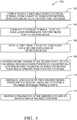
- STEP 102 FORM A DOUBLE-ENDED MALE BLADE ELECTRICAL TERMINAL FROM A SHEET OF CONDUCTIVE MATERIAL HAVING A UNIFORM FIRST THICKNESS, includes forming the double-ended terminal 30 from a sheet of conductive material having the uniform first thickness T1.
- the double-ended terminal 30 may be formed from a sheet of a conductive material, such as copper alloys, brass, or beryllium copper.
- the double-ended terminal 30 may be formed by cutting, stamping, fine blanking, or any other method of forming a terminal blank from a sheet of conductive material known to those skilled in the art.
- the first thickness T1 of the sheet is about 0.8 mm (0.8 +0.052/- 0.0 mm).
- the second blade width W2 may be greater than the first blade width W1 and one side of the first blade 40 and one side of the second blade 42 may be coplanar.
Landscapes
- Engineering & Computer Science (AREA)
- Manufacturing & Machinery (AREA)
- Coupling Device And Connection With Printed Circuit (AREA)
- Manufacturing Of Electrical Connectors (AREA)
- Structures For Mounting Electric Components On Printed Circuit Boards (AREA)
Claims (11)
- Borne électrique (30) à lame mâle à deux extrémités, comprenant :une première lame (40), laquelle première lame est configurée pour être connectée à une borne femelle correspondante dans un dispositif électrique et présente une première épaisseur uniforme (T1) ; etune seconde lame (42), laquelle seconde lame est configurée pour être connectée à une borne femelle correspondante dans un connecteur électrique et présente une zone mésiale estampée (44) qui caractérise une seconde épaisseur uniforme (T2), la seconde épaisseur (T2) étant supérieure à la première épaisseur (T1),caractérisée en ce qu'une première extrémité distale (56) de la première lame (40) et une seconde extrémité distale (58) de la seconde lame (42) sont biseautées et dans laquelle une extrémité avant (60) de la zone estampée (44) proche de la seconde extrémité distale (58) définit une forme de triangle isocèle arrondi (62), les côtés (66) de la zone estampée (44) sont parallèles aux côtés (68) de la seconde lame (42) et une extrémité arrière (70) de la zone estampée (44) est dotée de coins arrondis (72).
- Borne électrique (30) selon la revendication 1, dans laquelle la première épaisseur (T1) est d'environ 0,8 millimètre et la seconde épaisseur (T2) est d'environ 1,2 millimètre.
- Borne électrique (30) selon l'une quelconque des revendications 1 à 2, dans laquelle un côté de la première lame (40) et un côté de la seconde lame (42) sont coplanaires.
- Borne électrique (30) selon l'une quelconque des revendications 1 à 3, dans laquelle la borne électrique (30) définit un épaulement (74) entre la première lame (40) et la seconde lame (42), ledit épaulement (74) ayant une largeur d'épaulement (Ws) qui est supérieure à une première largeur de lame (W1) et à une seconde largeur de lame (W2).
- Borne électrique (30) selon la revendication 1, dans laquelle deux côtés (64) de l'extrémité avant (60) de la zone estampée (44) définissent un angle de 30 degrés par rapport à un axe longitudinal de la borne électrique (30).
- Borne électrique (30) selon l'une quelconque des revendications 4 à 5, dans laquelle la seconde largeur de lame (W2) est supérieure à la première largeur de lame (W1).
- Ensemble formant carte à circuits imprimés (14), comprenant :un substrat diélectrique (20) ;une trace conductrice (38) disposée sur une surface du substrat (20) ; etune borne électrique à lame mâle à double extrémité (30) selon l'une quelconque des revendications 1 à 6, ladite borne électrique (30) étant disposée dans une ouverture (32) définie par le substrat (20), dans laquelle la seconde lame (42) est configurée pour être connectée à une borne femelle correspondante dans un connecteur électrique et dans laquelle la première lame (40) est configurée pour être connectée à une borne femelle correspondante dans un dispositif électrique.
- Ensemble formant carte à circuits imprimés (14) selon la revendication 7, dans lequel la première lame (40) dépasse d'une première surface (20) du substrat (20) et la seconde lame (42) dépasse d'une seconde surface (22) du substrat (20) opposée à la première surface (20).
- Ensemble formant carte à circuits imprimés (14) selon la revendication 8, dans lequel le dispositif électrique inclut une liaison fusible et/ou un relais électromécanique.
- Procédé (100) de fabrication d'une borne électrique à lame mâle à deux extrémités (30) selon l'une quelconque des revendications 1 à 6, ledit procédé (100) comprenant les étapes consistant à :former (102) la borne électrique à lame mâle à deux extrémités (30) à partir d'une feuille de matériau conducteur ayant la première épaisseur uniforme (T1) ; etestamper (108) une zone mésiale (44) de la seconde lame (42) de sorte que la zone mésiale (44) soit caractérisée par la seconde épaisseur uniforme (T2), comprenant en outre les étapes consistant à :biseauter (106) une première extrémité distale (56) de la première lame (40) et une seconde extrémité distale (58) de la seconde lame (42) ;caractérisé par les étapes consistant à :estamper (110) une extrémité avant (60) de la zone estampée (44) proche de la seconde extrémité distale (58) pour définir une forme de triangle isocèle arrondi (62) ; etestamper (112) une extrémité arrière (70) de la zone estampée (44) pour définir une paire de coins arrondis (72), les côtés (66) de la zone estampée (44) étant parallèles aux côtés (68) de la seconde lame (42).
- Procédé (100) selon la revendication 10, comprenant en outre l'étape consistant à former (104) la borne électrique (30) pour définir un épaulement (74) entre la première lame (40) et la seconde lame (42), ledit épaulement (74) ayant une largeur d'épaulement (Ws) qui est supérieure à une première largeur de lame (W1) et à une seconde largeur de lame (W2).
Applications Claiming Priority (1)
| Application Number | Priority Date | Filing Date | Title |
|---|---|---|---|
| US14/321,922 US9331413B2 (en) | 2014-07-02 | 2014-07-02 | Dual thickness double-ended male blade terminal |
Publications (2)
| Publication Number | Publication Date |
|---|---|
| EP2963739A1 EP2963739A1 (fr) | 2016-01-06 |
| EP2963739B1 true EP2963739B1 (fr) | 2018-12-19 |
Family
ID=53539484
Family Applications (1)
| Application Number | Title | Priority Date | Filing Date |
|---|---|---|---|
| EP15173604.8A Active EP2963739B1 (fr) | 2014-07-02 | 2015-06-24 | Borne à lame mâle à deux extrémités double épaisseur et procédé de fabrication |
Country Status (6)
| Country | Link |
|---|---|
| US (1) | US9331413B2 (fr) |
| EP (1) | EP2963739B1 (fr) |
| JP (1) | JP6124953B2 (fr) |
| KR (1) | KR101683386B1 (fr) |
| CN (1) | CN105322330B (fr) |
| BR (1) | BR102015013010A2 (fr) |
Families Citing this family (5)
| Publication number | Priority date | Publication date | Assignee | Title |
|---|---|---|---|---|
| JP6183667B2 (ja) * | 2015-10-01 | 2017-08-23 | 住友電装株式会社 | コネクタ |
| US10349539B2 (en) * | 2017-10-03 | 2019-07-09 | Aptiv Technologies Limited | Vehicle electrical center and method of manufacturing same |
| EP3637564B1 (fr) | 2018-10-08 | 2021-06-09 | Aptiv Technologies Limited | Procédé de fabrication d'un ensemble de câblage électrique |
| CN117293575A (zh) * | 2020-03-26 | 2023-12-26 | 上海莫仕连接器有限公司 | 电连接装置及端子 |
| US20210408710A1 (en) * | 2020-06-29 | 2021-12-30 | Microsoft Technology Licensing, Llc | Systems and methods for improving safety on electronic device connections |
Family Cites Families (22)
| Publication number | Priority date | Publication date | Assignee | Title |
|---|---|---|---|---|
| US2130424A (en) * | 1936-06-29 | 1938-09-20 | Albert T Otto & Sons Inc | Attachment plug |
| US2752580A (en) | 1953-04-27 | 1956-06-26 | Charles A Shewmaker | Printed circuit board and terminal connections |
| US2811702A (en) | 1956-06-21 | 1957-10-29 | Malco Tool & Mfg Co | Terminal pin for printed circuit board |
| US3977075A (en) * | 1971-10-28 | 1976-08-31 | Amp Incorporated | Method of fabricating multi-layer printed circuit board |
| JPS5968187A (ja) * | 1982-10-13 | 1984-04-18 | 富士通株式会社 | 端子構造 |
| US4923414A (en) | 1989-07-03 | 1990-05-08 | E. I. Du Pont De Nemours And Company | Compliant section for circuit board contact elements |
| US5023752A (en) * | 1989-10-31 | 1991-06-11 | General Motors Corporation | Electrical power distribution center |
| US5046960A (en) * | 1990-12-20 | 1991-09-10 | Amp Incorporated | High density connector system |
| US5207603A (en) * | 1992-06-02 | 1993-05-04 | Molex Incorporated | Dual thickness blade type electrical terminal |
| EP0713263B1 (fr) * | 1994-11-17 | 2000-09-06 | Molex Incorporated | Structure de connexion enfichable autoverrouillant |
| US5582519A (en) * | 1994-12-15 | 1996-12-10 | The Whitaker Corporation | Make-first-break-last ground connections |
| US5831814A (en) | 1997-03-14 | 1998-11-03 | General Motors Corporation | Electrical center bus plate assembly |
| US6008982A (en) * | 1998-05-20 | 1999-12-28 | General Motors Corporation | Low profile electrical distribution center and method of making a bus subassembly therefor |
| US6062916A (en) * | 1998-07-14 | 2000-05-16 | General Motors Corporation | Printed circuit board with pass through bussed terminal system for a bussed electrical distribution center |
| JP2002058134A (ja) * | 2000-08-09 | 2002-02-22 | Auto Network Gijutsu Kenkyusho:Kk | 電子制御ユニットの搭載構造 |
| US7955133B2 (en) * | 2008-04-23 | 2011-06-07 | Littelfuse, Inc. | Flexible power distribution module |
| JP5077190B2 (ja) * | 2008-10-28 | 2012-11-21 | 住友電装株式会社 | プリント基板 |
| JP5224067B2 (ja) * | 2009-11-11 | 2013-07-03 | 住友電装株式会社 | 基板用端子およびこれを備えた基板用コネクタ |
| JP5570395B2 (ja) | 2010-10-08 | 2014-08-13 | モレックス インコーポレイテド | シートコネクタ |
| US20120268864A1 (en) | 2011-04-21 | 2012-10-25 | Delphi Technologies, Inc. | Apparatus having plurality of openings to access removable electronic devices some of which have electrical connections using no circuit board trace |
| US8961197B2 (en) * | 2012-06-08 | 2015-02-24 | Lear Corporation | Fuse housing assembly |
| CN202662858U (zh) * | 2012-06-25 | 2013-01-09 | 德尔福派克电气系统有限公司 | 一种大电流产品导电部位接触机构 |
-
2014
- 2014-07-02 US US14/321,922 patent/US9331413B2/en active Active
-
2015
- 2015-06-03 BR BR102015013010A patent/BR102015013010A2/pt not_active Application Discontinuation
- 2015-06-12 CN CN201510323420.8A patent/CN105322330B/zh active Active
- 2015-06-24 EP EP15173604.8A patent/EP2963739B1/fr active Active
- 2015-06-29 KR KR1020150091744A patent/KR101683386B1/ko active IP Right Grant
- 2015-07-01 JP JP2015132463A patent/JP6124953B2/ja active Active
Non-Patent Citations (1)
| Title |
|---|
| None * |
Also Published As
| Publication number | Publication date |
|---|---|
| US20160006155A1 (en) | 2016-01-07 |
| CN105322330B (zh) | 2018-06-12 |
| EP2963739A1 (fr) | 2016-01-06 |
| US9331413B2 (en) | 2016-05-03 |
| CN105322330A (zh) | 2016-02-10 |
| KR101683386B1 (ko) | 2016-12-06 |
| JP6124953B2 (ja) | 2017-05-10 |
| KR20160004196A (ko) | 2016-01-12 |
| JP2016028381A (ja) | 2016-02-25 |
| BR102015013010A2 (pt) | 2016-07-19 |
Similar Documents
| Publication | Publication Date | Title |
|---|---|---|
| US6062916A (en) | Printed circuit board with pass through bussed terminal system for a bussed electrical distribution center | |
| EP2963739B1 (fr) | Borne à lame mâle à deux extrémités double épaisseur et procédé de fabrication | |
| CN101364679B (zh) | 电连接组件 | |
| EP1506597B1 (fr) | Connecteur electrique | |
| US7556543B2 (en) | One-piece PC board magnet wire terminal | |
| JP5140125B2 (ja) | コネクタ端子の製造方法およびコネクタ端子 | |
| EP2284952A1 (fr) | Module haute frequence et dispositif sans fil | |
| JP2005353567A (ja) | プレスフィット端子およびそれを用いた回路基板モジュール | |
| US11050200B2 (en) | Electrical connector with hermaphroditic terminal and housing | |
| KR200293510Y1 (ko) | 가요성 기판에 장착되는 단자 핀을 가진 전기 커넥터 조립체 | |
| US8371871B1 (en) | Terminal with compliant barb | |
| US20160181710A1 (en) | Printed Circuit Board Assembly Having Improved Terminals | |
| KR100304514B1 (ko) | 평평한가요성회로를사용하는전자장치및그제조방법 | |
| US6203386B1 (en) | Terminal blades mounted on flexible substrates | |
| JP5622051B2 (ja) | 基板用端子およびそれを用いた基板用コネクタ | |
| US20170346203A1 (en) | Board terminal | |
| US11791575B2 (en) | Circuit board with U-shaped electrical terminal | |
| US20240120671A1 (en) | Connector and electronic device | |
| US20140291002A1 (en) | Printed circuit board module | |
| WO2019111583A1 (fr) | Dispositif de connexion électrique | |
| JP2023167498A (ja) | 配線接続方法およびプラグコネクタ | |
| WO2013004576A1 (fr) | Élément de contact électrique | |
| CN115693320A (zh) | 部件间连接构造 | |
| JP2008277040A (ja) | コネクタ | |
| JP2018055938A (ja) | 電子装置及び圧接端子 |
Legal Events
| Date | Code | Title | Description |
|---|---|---|---|
| PUAI | Public reference made under article 153(3) epc to a published international application that has entered the european phase |
Free format text: ORIGINAL CODE: 0009012 |
|
| AK | Designated contracting states |
Kind code of ref document: A1 Designated state(s): AL AT BE BG CH CY CZ DE DK EE ES FI FR GB GR HR HU IE IS IT LI LT LU LV MC MK MT NL NO PL PT RO RS SE SI SK SM TR |
|
| AX | Request for extension of the european patent |
Extension state: BA ME |
|
| 17P | Request for examination filed |
Effective date: 20160706 |
|
| RBV | Designated contracting states (corrected) |
Designated state(s): AL AT BE BG CH CY CZ DE DK EE ES FI FR GB GR HR HU IE IS IT LI LT LU LV MC MK MT NL NO PL PT RO RS SE SI SK SM TR |
|
| STAA | Information on the status of an ep patent application or granted ep patent |
Free format text: STATUS: EXAMINATION IS IN PROGRESS |
|
| 17Q | First examination report despatched |
Effective date: 20180125 |
|
| GRAP | Despatch of communication of intention to grant a patent |
Free format text: ORIGINAL CODE: EPIDOSNIGR1 |
|
| STAA | Information on the status of an ep patent application or granted ep patent |
Free format text: STATUS: GRANT OF PATENT IS INTENDED |
|
| RIC1 | Information provided on ipc code assigned before grant |
Ipc: H01R 13/05 20060101ALI20180705BHEP Ipc: H01R 13/04 20060101ALI20180705BHEP Ipc: H01R 12/58 20110101AFI20180705BHEP Ipc: H01R 43/16 20060101ALI20180705BHEP |
|
| INTG | Intention to grant announced |
Effective date: 20180731 |
|
| GRAS | Grant fee paid |
Free format text: ORIGINAL CODE: EPIDOSNIGR3 |
|
| GRAA | (expected) grant |
Free format text: ORIGINAL CODE: 0009210 |
|
| STAA | Information on the status of an ep patent application or granted ep patent |
Free format text: STATUS: THE PATENT HAS BEEN GRANTED |
|
| AK | Designated contracting states |
Kind code of ref document: B1 Designated state(s): AL AT BE BG CH CY CZ DE DK EE ES FI FR GB GR HR HU IE IS IT LI LT LU LV MC MK MT NL NO PL PT RO RS SE SI SK SM TR |
|
| RAP1 | Party data changed (applicant data changed or rights of an application transferred) |
Owner name: APTIV TECHNOLOGIES LIMITED |
|
| REG | Reference to a national code |
Ref country code: GB Ref legal event code: FG4D |
|
| REG | Reference to a national code |
Ref country code: CH Ref legal event code: EP |
|
| REG | Reference to a national code |
Ref country code: IE Ref legal event code: FG4D |
|
| REG | Reference to a national code |
Ref country code: DE Ref legal event code: R096 Ref document number: 602015021765 Country of ref document: DE |
|
| REG | Reference to a national code |
Ref country code: AT Ref legal event code: REF Ref document number: 1079689 Country of ref document: AT Kind code of ref document: T Effective date: 20190115 |
|
| REG | Reference to a national code |
Ref country code: NL Ref legal event code: MP Effective date: 20181219 |
|
| PG25 | Lapsed in a contracting state [announced via postgrant information from national office to epo] |
Ref country code: FI Free format text: LAPSE BECAUSE OF FAILURE TO SUBMIT A TRANSLATION OF THE DESCRIPTION OR TO PAY THE FEE WITHIN THE PRESCRIBED TIME-LIMIT Effective date: 20181219 Ref country code: HR Free format text: LAPSE BECAUSE OF FAILURE TO SUBMIT A TRANSLATION OF THE DESCRIPTION OR TO PAY THE FEE WITHIN THE PRESCRIBED TIME-LIMIT Effective date: 20181219 Ref country code: NO Free format text: LAPSE BECAUSE OF FAILURE TO SUBMIT A TRANSLATION OF THE DESCRIPTION OR TO PAY THE FEE WITHIN THE PRESCRIBED TIME-LIMIT Effective date: 20190319 Ref country code: LV Free format text: LAPSE BECAUSE OF FAILURE TO SUBMIT A TRANSLATION OF THE DESCRIPTION OR TO PAY THE FEE WITHIN THE PRESCRIBED TIME-LIMIT Effective date: 20181219 Ref country code: BG Free format text: LAPSE BECAUSE OF FAILURE TO SUBMIT A TRANSLATION OF THE DESCRIPTION OR TO PAY THE FEE WITHIN THE PRESCRIBED TIME-LIMIT Effective date: 20190319 Ref country code: LT Free format text: LAPSE BECAUSE OF FAILURE TO SUBMIT A TRANSLATION OF THE DESCRIPTION OR TO PAY THE FEE WITHIN THE PRESCRIBED TIME-LIMIT Effective date: 20181219 |
|
| REG | Reference to a national code |
Ref country code: LT Ref legal event code: MG4D |
|
| REG | Reference to a national code |
Ref country code: AT Ref legal event code: MK05 Ref document number: 1079689 Country of ref document: AT Kind code of ref document: T Effective date: 20181219 |
|
| PG25 | Lapsed in a contracting state [announced via postgrant information from national office to epo] |
Ref country code: AL Free format text: LAPSE BECAUSE OF FAILURE TO SUBMIT A TRANSLATION OF THE DESCRIPTION OR TO PAY THE FEE WITHIN THE PRESCRIBED TIME-LIMIT Effective date: 20181219 Ref country code: GR Free format text: LAPSE BECAUSE OF FAILURE TO SUBMIT A TRANSLATION OF THE DESCRIPTION OR TO PAY THE FEE WITHIN THE PRESCRIBED TIME-LIMIT Effective date: 20190320 Ref country code: SE Free format text: LAPSE BECAUSE OF FAILURE TO SUBMIT A TRANSLATION OF THE DESCRIPTION OR TO PAY THE FEE WITHIN THE PRESCRIBED TIME-LIMIT Effective date: 20181219 Ref country code: RS Free format text: LAPSE BECAUSE OF FAILURE TO SUBMIT A TRANSLATION OF THE DESCRIPTION OR TO PAY THE FEE WITHIN THE PRESCRIBED TIME-LIMIT Effective date: 20181219 |
|
| PG25 | Lapsed in a contracting state [announced via postgrant information from national office to epo] |
Ref country code: NL Free format text: LAPSE BECAUSE OF FAILURE TO SUBMIT A TRANSLATION OF THE DESCRIPTION OR TO PAY THE FEE WITHIN THE PRESCRIBED TIME-LIMIT Effective date: 20181219 |
|
| PG25 | Lapsed in a contracting state [announced via postgrant information from national office to epo] |
Ref country code: IT Free format text: LAPSE BECAUSE OF FAILURE TO SUBMIT A TRANSLATION OF THE DESCRIPTION OR TO PAY THE FEE WITHIN THE PRESCRIBED TIME-LIMIT Effective date: 20181219 Ref country code: CZ Free format text: LAPSE BECAUSE OF FAILURE TO SUBMIT A TRANSLATION OF THE DESCRIPTION OR TO PAY THE FEE WITHIN THE PRESCRIBED TIME-LIMIT Effective date: 20181219 Ref country code: PT Free format text: LAPSE BECAUSE OF FAILURE TO SUBMIT A TRANSLATION OF THE DESCRIPTION OR TO PAY THE FEE WITHIN THE PRESCRIBED TIME-LIMIT Effective date: 20190419 Ref country code: PL Free format text: LAPSE BECAUSE OF FAILURE TO SUBMIT A TRANSLATION OF THE DESCRIPTION OR TO PAY THE FEE WITHIN THE PRESCRIBED TIME-LIMIT Effective date: 20181219 Ref country code: ES Free format text: LAPSE BECAUSE OF FAILURE TO SUBMIT A TRANSLATION OF THE DESCRIPTION OR TO PAY THE FEE WITHIN THE PRESCRIBED TIME-LIMIT Effective date: 20181219 |
|
| PG25 | Lapsed in a contracting state [announced via postgrant information from national office to epo] |
Ref country code: EE Free format text: LAPSE BECAUSE OF FAILURE TO SUBMIT A TRANSLATION OF THE DESCRIPTION OR TO PAY THE FEE WITHIN THE PRESCRIBED TIME-LIMIT Effective date: 20181219 Ref country code: SM Free format text: LAPSE BECAUSE OF FAILURE TO SUBMIT A TRANSLATION OF THE DESCRIPTION OR TO PAY THE FEE WITHIN THE PRESCRIBED TIME-LIMIT Effective date: 20181219 Ref country code: RO Free format text: LAPSE BECAUSE OF FAILURE TO SUBMIT A TRANSLATION OF THE DESCRIPTION OR TO PAY THE FEE WITHIN THE PRESCRIBED TIME-LIMIT Effective date: 20181219 Ref country code: SK Free format text: LAPSE BECAUSE OF FAILURE TO SUBMIT A TRANSLATION OF THE DESCRIPTION OR TO PAY THE FEE WITHIN THE PRESCRIBED TIME-LIMIT Effective date: 20181219 Ref country code: IS Free format text: LAPSE BECAUSE OF FAILURE TO SUBMIT A TRANSLATION OF THE DESCRIPTION OR TO PAY THE FEE WITHIN THE PRESCRIBED TIME-LIMIT Effective date: 20190419 |
|
| REG | Reference to a national code |
Ref country code: DE Ref legal event code: R097 Ref document number: 602015021765 Country of ref document: DE |
|
| PLBE | No opposition filed within time limit |
Free format text: ORIGINAL CODE: 0009261 |
|
| STAA | Information on the status of an ep patent application or granted ep patent |
Free format text: STATUS: NO OPPOSITION FILED WITHIN TIME LIMIT |
|
| PG25 | Lapsed in a contracting state [announced via postgrant information from national office to epo] |
Ref country code: DK Free format text: LAPSE BECAUSE OF FAILURE TO SUBMIT A TRANSLATION OF THE DESCRIPTION OR TO PAY THE FEE WITHIN THE PRESCRIBED TIME-LIMIT Effective date: 20181219 Ref country code: AT Free format text: LAPSE BECAUSE OF FAILURE TO SUBMIT A TRANSLATION OF THE DESCRIPTION OR TO PAY THE FEE WITHIN THE PRESCRIBED TIME-LIMIT Effective date: 20181219 |
|
| 26N | No opposition filed |
Effective date: 20190920 |
|
| PG25 | Lapsed in a contracting state [announced via postgrant information from national office to epo] |
Ref country code: MC Free format text: LAPSE BECAUSE OF FAILURE TO SUBMIT A TRANSLATION OF THE DESCRIPTION OR TO PAY THE FEE WITHIN THE PRESCRIBED TIME-LIMIT Effective date: 20181219 |
|
| REG | Reference to a national code |
Ref country code: CH Ref legal event code: PL |
|
| PG25 | Lapsed in a contracting state [announced via postgrant information from national office to epo] |
Ref country code: SI Free format text: LAPSE BECAUSE OF FAILURE TO SUBMIT A TRANSLATION OF THE DESCRIPTION OR TO PAY THE FEE WITHIN THE PRESCRIBED TIME-LIMIT Effective date: 20181219 |
|
| REG | Reference to a national code |
Ref country code: BE Ref legal event code: MM Effective date: 20190630 |
|
| PG25 | Lapsed in a contracting state [announced via postgrant information from national office to epo] |
Ref country code: TR Free format text: LAPSE BECAUSE OF FAILURE TO SUBMIT A TRANSLATION OF THE DESCRIPTION OR TO PAY THE FEE WITHIN THE PRESCRIBED TIME-LIMIT Effective date: 20181219 |
|
| PG25 | Lapsed in a contracting state [announced via postgrant information from national office to epo] |
Ref country code: IE Free format text: LAPSE BECAUSE OF NON-PAYMENT OF DUE FEES Effective date: 20190624 |
|
| PG25 | Lapsed in a contracting state [announced via postgrant information from national office to epo] |
Ref country code: CH Free format text: LAPSE BECAUSE OF NON-PAYMENT OF DUE FEES Effective date: 20190630 Ref country code: LI Free format text: LAPSE BECAUSE OF NON-PAYMENT OF DUE FEES Effective date: 20190630 Ref country code: BE Free format text: LAPSE BECAUSE OF NON-PAYMENT OF DUE FEES Effective date: 20190630 Ref country code: LU Free format text: LAPSE BECAUSE OF NON-PAYMENT OF DUE FEES Effective date: 20190624 |
|
| PG25 | Lapsed in a contracting state [announced via postgrant information from national office to epo] |
Ref country code: CY Free format text: LAPSE BECAUSE OF FAILURE TO SUBMIT A TRANSLATION OF THE DESCRIPTION OR TO PAY THE FEE WITHIN THE PRESCRIBED TIME-LIMIT Effective date: 20181219 |
|
| PG25 | Lapsed in a contracting state [announced via postgrant information from national office to epo] |
Ref country code: HU Free format text: LAPSE BECAUSE OF FAILURE TO SUBMIT A TRANSLATION OF THE DESCRIPTION OR TO PAY THE FEE WITHIN THE PRESCRIBED TIME-LIMIT; INVALID AB INITIO Effective date: 20150624 Ref country code: MT Free format text: LAPSE BECAUSE OF FAILURE TO SUBMIT A TRANSLATION OF THE DESCRIPTION OR TO PAY THE FEE WITHIN THE PRESCRIBED TIME-LIMIT Effective date: 20181219 |
|
| PG25 | Lapsed in a contracting state [announced via postgrant information from national office to epo] |
Ref country code: MK Free format text: LAPSE BECAUSE OF FAILURE TO SUBMIT A TRANSLATION OF THE DESCRIPTION OR TO PAY THE FEE WITHIN THE PRESCRIBED TIME-LIMIT Effective date: 20181219 |
|
| P01 | Opt-out of the competence of the unified patent court (upc) registered |
Effective date: 20230424 |
|
| PGFP | Annual fee paid to national office [announced via postgrant information from national office to epo] |
Ref country code: DE Payment date: 20230621 Year of fee payment: 9 |
|
| PGFP | Annual fee paid to national office [announced via postgrant information from national office to epo] |
Ref country code: GB Payment date: 20240625 Year of fee payment: 10 |
|
| PGFP | Annual fee paid to national office [announced via postgrant information from national office to epo] |
Ref country code: FR Payment date: 20240627 Year of fee payment: 10 |