EP2963401A2 - Derotationsanordnung und verfahren für einen abtastsensor - Google Patents
Derotationsanordnung und verfahren für einen abtastsensor Download PDFInfo
- Publication number
- EP2963401A2 EP2963401A2 EP15170913.6A EP15170913A EP2963401A2 EP 2963401 A2 EP2963401 A2 EP 2963401A2 EP 15170913 A EP15170913 A EP 15170913A EP 2963401 A2 EP2963401 A2 EP 2963401A2
- Authority
- EP
- European Patent Office
- Prior art keywords
- housing
- sensor
- dewar
- assembly
- mount
- Prior art date
- Legal status (The legal status is an assumption and is not a legal conclusion. Google has not performed a legal analysis and makes no representation as to the accuracy of the status listed.)
- Granted
Links
Images


Classifications
-
- G—PHYSICS
- G01—MEASURING; TESTING
- G01J—MEASUREMENT OF INTENSITY, VELOCITY, SPECTRAL CONTENT, POLARISATION, PHASE OR PULSE CHARACTERISTICS OF INFRARED, VISIBLE OR ULTRAVIOLET LIGHT; COLORIMETRY; RADIATION PYROMETRY
- G01J1/00—Photometry, e.g. photographic exposure meter
- G01J1/02—Details
- G01J1/0271—Housings; Attachments or accessories for photometers
-
- G—PHYSICS
- G01—MEASURING; TESTING
- G01J—MEASUREMENT OF INTENSITY, VELOCITY, SPECTRAL CONTENT, POLARISATION, PHASE OR PULSE CHARACTERISTICS OF INFRARED, VISIBLE OR ULTRAVIOLET LIGHT; COLORIMETRY; RADIATION PYROMETRY
- G01J1/00—Photometry, e.g. photographic exposure meter
- G01J1/02—Details
- G01J1/04—Optical or mechanical part supplementary adjustable parts
- G01J1/0403—Mechanical elements; Supports for optical elements; Scanning arrangements
-
- G—PHYSICS
- G01—MEASURING; TESTING
- G01J—MEASUREMENT OF INTENSITY, VELOCITY, SPECTRAL CONTENT, POLARISATION, PHASE OR PULSE CHARACTERISTICS OF INFRARED, VISIBLE OR ULTRAVIOLET LIGHT; COLORIMETRY; RADIATION PYROMETRY
- G01J5/00—Radiation pyrometry, e.g. infrared or optical thermometry
- G01J5/02—Constructional details
- G01J5/04—Casings
- G01J5/041—Mountings in enclosures or in a particular environment
- G01J5/044—Environment with strong vibrations or shocks
-
- G—PHYSICS
- G01—MEASURING; TESTING
- G01J—MEASUREMENT OF INTENSITY, VELOCITY, SPECTRAL CONTENT, POLARISATION, PHASE OR PULSE CHARACTERISTICS OF INFRARED, VISIBLE OR ULTRAVIOLET LIGHT; COLORIMETRY; RADIATION PYROMETRY
- G01J5/00—Radiation pyrometry, e.g. infrared or optical thermometry
- G01J5/02—Constructional details
- G01J5/04—Casings
- G01J5/047—Mobile mounting; Scanning arrangements
-
- G—PHYSICS
- G01—MEASURING; TESTING
- G01J—MEASUREMENT OF INTENSITY, VELOCITY, SPECTRAL CONTENT, POLARISATION, PHASE OR PULSE CHARACTERISTICS OF INFRARED, VISIBLE OR ULTRAVIOLET LIGHT; COLORIMETRY; RADIATION PYROMETRY
- G01J5/00—Radiation pyrometry, e.g. infrared or optical thermometry
- G01J5/02—Constructional details
- G01J5/06—Arrangements for eliminating effects of disturbing radiation; Arrangements for compensating changes in sensitivity
- G01J5/061—Arrangements for eliminating effects of disturbing radiation; Arrangements for compensating changes in sensitivity by controlling the temperature of the apparatus or parts thereof, e.g. using cooling means or thermostats
-
- G—PHYSICS
- G01—MEASURING; TESTING
- G01J—MEASUREMENT OF INTENSITY, VELOCITY, SPECTRAL CONTENT, POLARISATION, PHASE OR PULSE CHARACTERISTICS OF INFRARED, VISIBLE OR ULTRAVIOLET LIGHT; COLORIMETRY; RADIATION PYROMETRY
- G01J5/00—Radiation pyrometry, e.g. infrared or optical thermometry
- G01J5/02—Constructional details
- G01J5/07—Arrangements for adjusting the solid angle of collected radiation, e.g. adjusting or orienting field of view, tracking position or encoding angular position
-
- G—PHYSICS
- G01—MEASURING; TESTING
- G01J—MEASUREMENT OF INTENSITY, VELOCITY, SPECTRAL CONTENT, POLARISATION, PHASE OR PULSE CHARACTERISTICS OF INFRARED, VISIBLE OR ULTRAVIOLET LIGHT; COLORIMETRY; RADIATION PYROMETRY
- G01J5/00—Radiation pyrometry, e.g. infrared or optical thermometry
- G01J5/02—Constructional details
- G01J5/08—Optical arrangements
- G01J5/0893—Arrangements to attach devices to a pyrometer, i.e. attaching an optical interface; Spatial relative arrangement of optical elements, e.g. folded beam path
-
- G—PHYSICS
- G02—OPTICS
- G02B—OPTICAL ELEMENTS, SYSTEMS OR APPARATUS
- G02B27/00—Optical systems or apparatus not provided for by any of the groups G02B1/00 - G02B26/00, G02B30/00
- G02B27/64—Imaging systems using optical elements for stabilisation of the lateral and angular position of the image
- G02B27/644—Imaging systems using optical elements for stabilisation of the lateral and angular position of the image compensating for large deviations, e.g. maintaining a fixed line of sight while a vehicle on which the system is mounted changes course
-
- G—PHYSICS
- G03—PHOTOGRAPHY; CINEMATOGRAPHY; ANALOGOUS TECHNIQUES USING WAVES OTHER THAN OPTICAL WAVES; ELECTROGRAPHY; HOLOGRAPHY
- G03B—APPARATUS OR ARRANGEMENTS FOR TAKING PHOTOGRAPHS OR FOR PROJECTING OR VIEWING THEM; APPARATUS OR ARRANGEMENTS EMPLOYING ANALOGOUS TECHNIQUES USING WAVES OTHER THAN OPTICAL WAVES; ACCESSORIES THEREFOR
- G03B17/00—Details of cameras or camera bodies; Accessories therefor
- G03B17/48—Details of cameras or camera bodies; Accessories therefor adapted for combination with other photographic or optical apparatus
-
- G—PHYSICS
- G01—MEASURING; TESTING
- G01J—MEASUREMENT OF INTENSITY, VELOCITY, SPECTRAL CONTENT, POLARISATION, PHASE OR PULSE CHARACTERISTICS OF INFRARED, VISIBLE OR ULTRAVIOLET LIGHT; COLORIMETRY; RADIATION PYROMETRY
- G01J5/00—Radiation pyrometry, e.g. infrared or optical thermometry
- G01J2005/0077—Imaging
Definitions
- the invention is related to optical scanning systems generally, and more particularly for a derotation assembly and method for a scanning sensor.
- an infrared sensor or other infrared imaging device generally must be cryogenically cooled for optimal performance. Accordingly, the infrared sensor generally is sealed in a vacuum-insulated container called a dewar, which is coupled to a compressor for circulating a cooling fluid through the dewar to maintain a temperature below ambient temperature.
- the present invention provides an assembly that enables precise mounting of a sensor with improved heat transfer and rotation compensation.
- An integrated dewar cooler assembly incorporating the sensor is mated to a motorized mount that is controlled to stabilize the rotation of the scene.
- the sensor is radially aligned relative to the axis of rotation in two adjustment stages. A first stage of adjustment controls the radial position of the sensor inside a bearing. And a second stage of adjustment controls radial translation of the entire assembly outside the bearing. Passive heat transfer is accomplished through a pair of heat sinks that effectively sandwich a hot expander end cap of the dewar, providing multiple heat paths.
- the entire dewar assembly is rotated during operation to stabilize the scene.
- the rotating mass of a cooling compressor coupled to the dewar is counter-balanced to avoid torque due to inertia.
- the present invention provides a scanning sensor derotation assembly that includes (a) a housing; (b) an integrated dewar cooling assembly mounted to the housing, the cooling assembly including a sensor mounted in a dewar; (c) a motor coupled to the housing to rotate the housing and the integrated dewar cooling assembly about an axis that passes through a center of the sensor; (d) a compressor fluidly coupled to the dewar, the compressor being mounted to the housing at a location offset from the axis; and (e) a counterweight mounted to the housing at a location offset from the axis and diametrically opposed to the compressor to counteract the inertia of the compressor when the housing is rotated.
- the counterweight may include multiple segments coupled together to adjust the counterweight. And the counterweight may include one or more bore holes for receipt of fine trim weights.
- the motor may be a toroidal motor.
- the integrated dewar cooling assembly may be centered in the housing.
- the sensor may be an infrared sensor.
- the surface of the sensor may be perpendicular to the rotation axis.
- the derotation assembly may further include a mounting bracket coupled to the motor that is mountable to a fixed object.
- the present invention also provides a mounting arrangement for an imaging sensor having a desired alignment axis.
- the mounting arrangement includes (a) a mount adjustably mountable in two transverse directions, the transverse directions lying in a common first plane; (b) a bearing mounted to the mount; (c) a housing coupled to the bearing for rotation relative to the mount about a rotation axis; (d) a translation plate adjustably mounted to the housing, the translation plate being adjustable relative to the housing in two transverse directions that lie in a common second plane that is parallel to the first plane; and (e) an imaging sensor connected to the translation plate and mounted in a fixed position relative to the translation plate, with the sensor's alignment axis transverse the first plane and the second plane.
- the mounting arrangement may include an integrated dewar cooling assembly that includes a dewar and the sensor, the sensor being mounted in a fixed position in the dewar and the dewar being mounted to the translation plate.
- the translation plate may be secured to the housing to align the alignment axis with the rotation axis.
- the translation plate may be adjustable in orthogonal directions.
- the sensor may be substantially planar and the alignment axis may pass through a center of the sensor and may be perpendicular to the sensor.
- the bearing may have an inner race and an outer race rotatable relative to the inner race, the outer race may be mounted to the mount and the inner race may be coupled to the housing.
- the mount may be mountable to a fixed object with multiple eccentric bushings and corresponding shoulder bolts, rotation of the eccentric bushings providing the adjustment in the mounting position.
- the mounting arrangement may further include a fastener and a through-hole in the mount for securing the mount to a fixed object and fixing the position of the mount relative to the fixed object.
- the mount may be an upper mount
- the bearing may be an upper mount bearing
- the mounting arrangement may further include a lower mount spaced from the upper mount, and a lower mount bearing mounted to the lower mount, the lower mount bearing having an outer race mounted to the lower mount and an inner race connected to the housing for rotation relative to the outer race; the lower mount being adjustably mounted so that inner races of the upper mount bearing and the lower mount bearing rotate about the rotation axis.
- the housing may further include a compressor mounted to the housing at a position radially offset from the rotation axis, and a counterweight mounted to the housing at a location diametrically opposite the compressor, the counterweight having approximately the same mass as the compressor and its contents.
- the housing may further have a through-hole and the translation plate has an elongated slots that generally aligns with the through-hole in the housing for a receipt of an adjustment tool having an eccentric portion at a distal end for the purpose of adjusting the position of the translation plate relative to the housing.
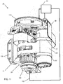
- the present invention provides a scanning sensor derotation assembly (also referred to as the derotation assembly) that facilitates maintaining a consistent field of view while the derotation assembly is moving relative to a field of view, such as when the derotation assembly is mounted on a vehicle like an airplane or a ship, and an associated mounting arrangement and method.
- the derotation assembly enables precise mounting of the sensor, improved heat transfer, and rotational-inertia compensation.
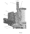
- the derotation assembly 20 includes an imaging sensor 22, such as an sensor for detecting infrared images, incorporated into an integrated dewar cooling assembly 24.
- the sensor 22 is electronically coupled to a controller 26, which may include a processor having an associated memory and program instructions, via a sensor cable 30, such as the illustrated ribbon cable.
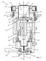
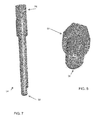
- the integrated dewar cooling assembly 24 (also referred to as the dewar assembly) includes a dewar 34 and the sensor 22 mounted in a sealed chamber 36 in the dewar 34.
- the sensor 22 is mounted in a fixed position relative to the dewar 34. Some sensors, such as infrared sensors, may require or perform better when cooled below ambient temperature.
- the dewar 34 is a double-walled vessel, typically of metal or silvered glass, with a vacuum between the walls, that is used to hold a fluid coolant, such as liquid nitrogen, at well-below-ambient temperature. The coolant keeps the sensor 22 and its immediate surroundings cooler than the ambient temperature outside the dewar 34, thereby improving the sensor's imaging capabilities.
- the illustrated dewar 34 has an elongated shape that extends along a longitudinal axis 38.
- the sealed chamber 36 has a window 40 that provides access for and may define an aperture to the sensor's field of view.
- the window 40 can be planar or curved and may be treated to provide desired optical properties.
- the sensor 22 generally captures an image of a desired field of view most efficiently when the center of the sensor 22 lies on an alignment axis aligned with a center of the desired field of view.
- the sensor 22 is substantially planar and the alignment axis passes through a center of the sensor 22 and is perpendicular to the sensor 22.
- the sensor 22 is securely mounted in the dewar 34 so that the longitudinal axis 38 of the dewar 34 passes through the center of the sensor 22, and thus the alignment axis is coincident with the longitudinal axis 38 of the dewar 34. That longitudinal axis 38 is then aligned with an axis about which the dewar assembly 24 is rotatable.
- Integrated dewar cooling assemblies are commercially available from Teledyne Judson Technologies of Montgomeryville, Pennsylvania, U.S.A., for example.
- the derotation assembly 20 also includes a housing 44 within which the dewar assembly 34 is centrally mounted for rotation about a rotation axis 46 that generally will be aligned with the center of the sensor 22, and thus also with the longitudinal axis 38 of the dewar 34 in the illustrated embodiment.
- the housing 44 is relatively open to facilitate heat removal from the dewar assembly 24 while also providing a support frame for the dewar 34 and associated components, and thus alternatively may be referred to as a frame as well as a housing.
- a portion of the housing 44 extends circumferentially around the dewar assembly 24.
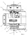
- the derotation assembly 20 provides a mounting arrangement for the sensor 22 that allows for a two-stage alignment process to radially align the center of the sensor 22 with the rotation axis 46.
- the mounting arrangement includes (a) a translation plate 50 adjustably mounted to the housing 44, (b) a bearing 66, and, (c) a mount 90 adjustably mountable in two transverse directions that lie in a common first plane.
- the bearing 66 is mounted to the mount 90, and the housing 44 is coupled to the bearing 66 for rotation relative to the mount 90 about the rotation axis 46.
- the translation plate 50 is adjustable relative to the housing 44 in two transverse directions that lie in a common second plane that is parallel to the first plane.
- the imaging sensor 22 is connected to the translation plate 50 and mounted in a fixed position relative to the translation plate 50 via the dewar 34.
- the dewar assembly 24 is mounted to the housing 44 through the translation plate 50, which is positioned between the dewar assembly 24 and the housing 44, and more particularly, from the dewar 34 being mounted to the translation plate 50.
- the translation plate 50 provides an adjustable mounting arrangement between the dewar assembly 24 and the housing 44 that allows the position of the sensor 22, generally the center of the sensor 22, to be adjusted along a direction within a plane perpendicular to the axis of rotation 46 to align the sensor 22 with the rotation axis 46.
- the translation plate 46 is affixed to the dewar assembly 24, specifically the outer surface of the dewar 34, and is attached to the housing 44 with a plurality of fasteners 52, such as screws, four of which are used to hold the translation plate 50 to the housing 44 in the illustrated embodiment. Once the dewar assembly 24 is aligned with the housing 44, the fasteners 52 are employed to fix the relative positions of the dewar assembly 24 and the housing 44.
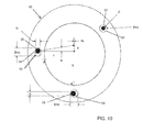
- the translation plate 50 has several openings therein for adjusting the position of the translation plate 50 relative to the housing 44 and for affixing the translation plate to the housing 44. At least one opening has an elongated shape that forms a slot 53 that allows the translation plate 50 to be moved along a length of the slot 53 before being fixed in a desired position.
- a removable adjustment tool 54 or multiple adjustment tools, may be used to adjust the position of the dewar assembly 24 relative to the housing 44.
- the illustrated adjustment tools 54 have an elongate shape with a faceted proximal end 56 for engagement by another tool, and an eccentric 58 on a distal end opposite the proximal end that is offset from an axis of rotation of the tool 54.
- the eccentric 58 is received in a through-hole or passage through the housing 44 and in a slot 53 in the translation plate 50 against which the eccentric 58 can act as the tool 54 is rotated.
- the eccentric 58 and the slot 53 act as a cam to adjust the position of the translation plate 50 in a direction parallel to the length dimension of the slot 53.
- the illustrated translation plate 50 includes two slots 53 that have length dimensions that extend in transverse directions in a common plane, more particularly orthogonal "X" and "Y" directions. This arrangement facilitates adjusting the position of the dewar assembly 24 during maintenance or after complete assembly, if needed.
- each slot 53 has a width D and a length D+d.
- the eccentric 58 at the end of the tool 54 has a diameter just less than D for receipt in the slot.
- the eccentric 58 rotates its cam-like action drives against the edge of the slot and moves the translation plate 50 in a direction transverse the length dimension of the slot 53. So, a slot 53 with a length dimension in the "Y" direction would be used to move the translation plate in the "X" direction as the eccentric 58 is rotated.
- the translation plate 50 can be adjusted by a distance, d, due to the offset of the eccentric 58 to the axis of rotation of the tool 54 and the length of the other slot 53 in the translation plate 50 in that direction.
- d due to the offset of the eccentric 58 to the axis of rotation of the tool 54 and the length of the other slot 53 in the translation plate 50 in that direction.
- the fasteners 52 can be employed to fix the dewar assembly 24 in place relative to the housing 44 and the translation plate 50.
- the openings 55 typically are enlarged to accommodate the adjustments in the position of the translation plate 50.
- the housing 44 is mounted to the bearing 66, which has an outer race 70 and an inner race 72 rotatable relative to the outer race 70.
- the housing 44 is affixed to the inner race 72 for rotation relative to the outer race 70.
- Adjustment of the dewar assembly 24 relative to the housing 44 may occur after the housing 44 is mounted in the bearing 66, in which case the adjustment of the dewar assembly 24 relative to the housing 44 also centers the sensor 22 relative to the axis of rotation of the inner race 72 of the bearing 66.
- the translation plate 50 thus is configured for adjusting a relative position of the sensor 22, and the optical assembly, relative to the inner race 72 of the bearing 66 within a plane perpendicular to the desired axis of rotation 46. Accordingly, the translation plate 50 provides an "inside-the-bearing" adjustment between the dewar assembly 24 and the housing 44.
- the housing 44 is separately coupled to a fixed object, such as a frame of a vehicle, through the mount.
- the mount is a bracket for securing the rotatable housing 44 to a fixed object, thereby providing a structure to support the rotatable housing 44 and relative to which the housing 44 can rotate.
- the illustrated mount includes two separate portions, an upper mounting bracket 90 (referred to simply as the upper mount) coupled to the housing 44 near a proximal end of the dewar assembly 24, and a lower mounting bracket 92 (referred to as the lower mount) spaced from the upper mount 90 and supporting a distal portion of the dewar assembly 24 via a bearing 96 (distinguished as the lower mount bearing) interposed between the lower mount 92 and the distal end of the dewar assembly 24.
- the bearing 66 can be referred to as the upper mount bearing 66.
- the outer race 70 of the upper mount bearing 66 is secured to the upper mount 90, and the inner race 72 is coupled to the housing 44.
- the upper mount 90 and the lower mount 92 each have off-center mounting holes for an outside-the-bearing alignment adjustment, described below.
- Bolts100 as in the illustrated embodiment, or other fasteners, inserted into enlarged through-holes 101 in the lower mount 92 allow the lower mount 92 to be secured in place after the dewar assembly 24 has been positioned relative to the housing 44, and the housing 44 has been secured to the upper mount 90.
- the upper mount's adjustment is similar to the adjustment of the translation plate 50 but it does not use the eccentric adjustment tools 54. Instead, eccentric bushings 102 and shoulder bolts 104 provide independent translation of the upper mount 90 relative to the fixed object to which it is to be secured in transverse, or orthogonal X- and Y-directions (typically but not necessarily perpendicular directions) in a common second plane.
- the shoulder bolts 104 are circumferentially spaced apart in tangentially-elongated openings or slots 105.
- the eccentric bushings 102 each have a faceted (such as hexagonal) head portion106 that is accessible to rotate the bushings 102 independently or together as needed, whereby rotation of the eccentric bushings 102 provides the adjustment in the mounting position.
- the shoulder bolts 104 are received in the slots 105, and rotating the bushings 102 drives the side of the bolt 104 against the side of the slot1 05, thereby moving the upper mount 90 in a direction transverse the length of the slot.
- the illustrated embodiment also includes a separate fastener 110 in the form of a screw without a bushing, spaced from the shoulder bolts 104 to secure the upper mount 90 in a third location in a through-hole 109 in the upper mount 90 and to help fix the position of the upper mount 90 once the adjustment is complete.
- the derotation alignment process occurs in two stages.
- an inner adjustment is performed to center the sensor 22 within the upper mount bearing 66 so that the center of the sensor 22 (and thus the field of view) corresponds with the center of the bearing 66 (aligning the center of the field of view with the axis of rotation 46).
- some components may need to be removed to permit the eccentric adjustment tool 54 to access the translation plate 40.
- the eccentric adjustment tools 54 are inserted through the housing 44 and into openings in the translation plate 40. Rotating one tool 54 at a first location causes a translation in a first direction, generally parallel to the plane of the translation plate 40.
- Rotating the other tool 54 at a second location causes a translation in a second direction transverse to and preferably perpendicular to the first direction, but in the same plane.
- the first direction and the second direction can be referred to as the X-direction and the Y-direction, respectively, both lying in the X-Y plane.
- the dewar assembly 24 and the housing 44 are adjusted to align the alignment axis of the sensor 22 with the center of the bearing 66. Once this inner adjustment is complete, screws or other fasteners 52 are tightened down to fix the position of the sensor 22 (via the dewar assembly 24) relative to the housing 44.
- the housing 44 is coupled to a fixed object, such as a frame of a vehicle, using eccentric bushings 102 and shoulder bolts 104, or cam bolts, that enable another translating adjustment.
- a first cam bushing 102 adjusts the position of the upper mount 90 in a first direction (X-direction), and a second cam bushing 102 adjusts the position of the upper mount 90 in a second (Y) direction transverse to the first direction but in the same plane.
- the adjustment is done while viewing a target with the sensor 22 to put the target image at the center of the sensor's field of view.
- the axis of rotation 46 desirably is within half a pixel of the center of the sensor 22.
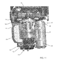
- the derotation assembly 20 also includes a motor 110, such as the illustrated direct drive toroidal motor, mounted to the upper mount 90 and coupled to the housing 44.
- An electromagnetic interference (EMI) shield 112 is mounted below the motor 110 to minimize or eliminate electromagnetic interference from the motor 110.
- the motor 110 has a stationary portion (sometimes referred to as a hub) 114 and a movable portion 116, both of which form concentric circles with an open center through which the axis of rotation 46 passes. The open center of the motor 110 also provides access to the window 40 in the dewar assembly 24, and thus the sensor 22.
- the stationary portion 114 of the motor 110 is affixed to the upper mount 90, and the movable portion 116 of the motor 110 engages the housing 44. This is a direct connection, without any intervening gears, thereby avoiding problems such as gear train backlash associated with imperfectly-meshing gear teeth.
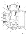
- the derotation assembly 20 further includes a compressor 120 mounted to the housing 44, radially offset from the axis of rotation 46 and spaced from the dewar assembly 24.
- the compressor 120 is secured to the housing 44 with a pair of hose clamps 122.
- the compressor 120 is fluidly-coupled to the dewar 34 to provide a cooling fluid, referred to as coolant, to the dewar 34 and to compress heated coolant received from the dewar 34 before returning it to the dewar 34.
- the coolant is circulated between the dewar 34 and the compressor 120 via coolant tubing 124 that provides a fluid passage.
- the coolant tubing 124 typically is flexible to facilitate connecting the compressor 120 to the dewar 34 and to accommodate any deformation or other movement of the housing 44 or dewar assembly 24 relative to the compressor 120 during rotation.
- a counterweight 130 is mounted to the housing 44 at a location radially offset from the rotation axis 46, spaced from the dewar assembly 24, and diametrically opposed to the compressor 120.
- the mass of the counterweight 130 is adjustable to neutrally balance the housing 44 and the compressor 120 so that the housing 44 rotates without or with minimal inertial torque.
- the counterweight 130 generally has approximately the same mass as the compressor 120 and its contents.
- the illustrated counterweight 130 has multiple segments, and segments can be added or removed to accurately counter the mass of the compressor 120.
- the counterweight 130 includes a mass or weight 132 that is incorporated into and thus is permanently integrated into the housing 44, and a main weight segment 134 that is secured to the housing 44 adjacent the weight 132 by a pair of fasteners 136, such as bolts, that permit the segment 134 to be changed if necessary.
- a trim weight 140 is sandwiched between the housing 44 and the main weight segment 134.
- a fine trim weight 142 is an additional option that may be added in bore holes 144 in the main weight 134.
- the bore holes 144 can be filled with threaded weights or a threaded plug can be inserted to hold a weight in the bore hole 144.
- the threaded plugs and the bolts 136 also add their mass to the counterweight 130.
- the counterweight 130 improves the reliability of the derotation assembly 20 more than flexible tubing alone or a rotatable fitting for the tubing as alternative
- the rotation of the dewar assembly 24 and the housing 44 is limited by a pair of stop blocks 146 secured to the upper mount 90 and a stop 147 mounted to the housing 44 between the stop blocks 146 to limit the rotation of the housing 44.
- the stop 147 and the stop blocks 146 cooperate to limit the rotation of the dewar assembly 24 and the housing 44 to about thirty degrees of travel, forward or reverse from a central position (a total of sixty degrees of travel). This amount of rotation generally is sufficient, and allows the controller 26 to be in a fixed, non-rotating position, rather than requiring the controller 26 to rotate with the sensor 22, and thereby preventing the need for a complicated solution to prevent the electrical cables connected to the controller from becoming entangled.
- the derotation assembly 20 also includes a pair of heatsinks 148 and 149 coupled to or incorporated into the dewar assembly 24 to help dissipate heat from the dewar 34 passively, without the energy required for the compressor 120.
- the illustrated heatsinks are mounted to a distal end of the dewar 34 opposite the window 40 at the proximal end, and include a lower heatsink portion 144 and an upper heatsink portion 146.
- the illustrated dewar 34 has an end cap 150 at a distal end, removed from the sensor 22 and the window 40, that has a relatively large mass and an outwardly-extending flange to help control and dissipate heat generated in the dewar 34.
- This flanged end cap 150 may be referred to as a hot end cap, and the heatsinks 148 and 149 sandwich the hot end cap 150 to passively transfer heat out of the dewar 34 through conduction and convection.
- the lower heatsink 148 has a relatively large mass in close contact with a corresponding surface at a distal end of the dewar 34 for transferring heat from the dewar 34 to the lower heatsink 148 and then the environment.
- the lower heatsink 148 has a plurality of longitudinally-extending fins 152 that also extend radially outward from the central mass. While the illustrated fins 152 are parallel to a longitudinal axis of the dewar 34, but other shapes or designs of fins or other protuberances may be equally or more suitable for a given application.
- the upper heatsink 149 has a surface in close contact with a circumferential portion of the dewar 34 proximally located relative to the lower heatsink 148 but on the other side of the flanged end cap 150.
- a plurality of rod-like fins 154 extend parallel to the rotation axis 46 and extend axially into a space in the housing 44 between the dewar 34 and the counterweights 130 and the compressor 120.
- a thermal heat transfer material may be applied between each heatsink 148 and 149 and an adjacent surface of the dewar 34 to improve the thermal contact and heat transfer.
- the heatsinks 148 and 149 provide a passive cooling element that assists the compressor 120 and can help to minimize the size and energy requirements of the compressor 120 to maintain the desired coolant temperature. And employing dual heatsinks 148 and 149 adjacent the hot end cap 150 provides multiple paths for the heat to escape the dewar 34, in addition to the active cooling provided by the coolant and the compressor 120.
- the derotation assembly 20 also includes a resolver 160, mounted to a distal end of the dewar assembly 24 for monitoring its rotational position about the rotation axis 46.
- a forty arc second (194 ⁇ rad) resolver for example, is sufficiently accurate for this assembly.
- the resolver 160 is electronically coupled to the controller 26 through a flexible electrical cable 162.
- the controller 26 is coupled to the upper mount 90 or the housing 44 or the fixed object to which the derotation assembly 20 is coupled, and generally does not need to rotate with the dewar assembly 24.
- the controller 26 receives data from the resolver 160 and the sensor 22 and controls the motor 110 to maintain the desired orientation of the sensor 22 relative to the field of view.
- the controller 26 also can be coupled to the sensor 22 to process the image data generated by the sensor 22.
- the controller 26 may control the compressor 120, if necessary. If the controller 120 is not coupled to the housing 44, flexible electrical connections or wireless connections may be used to provide the electrical connection as the housing 44 and the dewar assembly 24 rotate relative to the controller 26.
- an integrated dewar cooler assembly 24 incorporating the sensor 22 is mated to a motorized mount 90 and 110 that is controlled to stabilize the rotation of the scene.
- the sensor 22 is radially aligned relative to the axis of rotation 46 in two adjustment stages. A first stage of adjustment controls the radial position of the sensor 22 inside a bearing 66. And a second stage of adjustment controls radial translation of the entire assembly 20 outside the bearing 66. Passive heat transfer is accomplished through a pair of heatsinks 144 and 146 that effectively sandwich a hot expander end cap 150 of the dewar 34, providing multiple heat paths.
- the entire dewar assembly 24 is rotated during operation to stabilize the scene. And the rotating mass of a cooling compressor 120 coupled to the dewar 34 is counter-balanced to avoid torque due to inertia.
Landscapes
- Physics & Mathematics (AREA)
- General Physics & Mathematics (AREA)
- Spectroscopy & Molecular Physics (AREA)
- Optics & Photonics (AREA)
- Photometry And Measurement Of Optical Pulse Characteristics (AREA)
- Investigating Or Analyzing Materials Using Thermal Means (AREA)
- Cooling Or The Like Of Semiconductors Or Solid State Devices (AREA)
Applications Claiming Priority (1)
| Application Number | Priority Date | Filing Date | Title |
|---|---|---|---|
| US14/302,186 US9442003B2 (en) | 2014-06-11 | 2014-06-11 | Derotation assembly and method for a scanning sensor |
Publications (3)
| Publication Number | Publication Date |
|---|---|
| EP2963401A2 true EP2963401A2 (de) | 2016-01-06 |
| EP2963401A3 EP2963401A3 (de) | 2016-04-27 |
| EP2963401B1 EP2963401B1 (de) | 2020-10-14 |
Family
ID=53442492
Family Applications (1)
| Application Number | Title | Priority Date | Filing Date |
|---|---|---|---|
| EP15170913.6A Active EP2963401B1 (de) | 2014-06-11 | 2015-06-05 | Derotationsanordnung und verfahren für einen abtastsensor |
Country Status (3)
| Country | Link |
|---|---|
| US (1) | US9442003B2 (de) |
| EP (1) | EP2963401B1 (de) |
| IL (1) | IL238085B (de) |
Families Citing this family (4)
| Publication number | Priority date | Publication date | Assignee | Title |
|---|---|---|---|---|
| US20170192342A1 (en) * | 2016-01-05 | 2017-07-06 | ZEROTECH (Chongqing) Intelligence Technology Co., Ltd. | Camera apparatus |
| CN106441401A (zh) * | 2016-08-31 | 2017-02-22 | 武汉高芯科技有限公司 | 一种可拆卸的集成式变温测试杜瓦及其组件 |
| US10823824B2 (en) * | 2017-11-20 | 2020-11-03 | Ford Global Technologies, Llc | Sensor assembly |
| US11035934B2 (en) | 2017-11-20 | 2021-06-15 | Ford Global Technologies, Llc | Sensor assembly |
Family Cites Families (14)
| Publication number | Priority date | Publication date | Assignee | Title |
|---|---|---|---|---|
| US3219822A (en) | 1961-09-01 | 1965-11-23 | Lockheed Aircraft Corp | Infrared search system |
| US3786269A (en) * | 1971-12-17 | 1974-01-15 | Texas Instruments Inc | Method and apparatus of scanning electromagnetic radiation using rotating detectors-emitters and control circuit |
| US3977793A (en) | 1975-03-05 | 1976-08-31 | Texas Instruments Incorporated | Radiation energy receiver |
| US4717822A (en) * | 1986-08-04 | 1988-01-05 | Hughes Aircraft Company | Rosette scanning surveillance sensor |
| DE4235205A1 (de) * | 1991-10-30 | 1993-05-13 | Bechem Hannelore | Radial schlagende vibrationswalze zum verdichten/bearbeiten von boeden und dgl. |
| US5886450A (en) * | 1998-01-13 | 1999-03-23 | Kuehnle; Manfred R. | Toroidal electrical motor/generator |
| US6315648B1 (en) * | 1998-03-13 | 2001-11-13 | Dana L. Neer | Apparatus for pressure treating a surface |
| US6135727A (en) | 1999-02-16 | 2000-10-24 | Tecumseh Products Company | Detachably affixed counterweight and method of assembly |
| US7094043B2 (en) * | 2002-09-23 | 2006-08-22 | Tecumseh Products Company | Compressor having counterweight shield |
| US7587896B2 (en) * | 2006-05-12 | 2009-09-15 | Flir Systems, Inc. | Cooled infrared sensor assembly with compact configuration |
| DE102007042310A1 (de) * | 2007-09-06 | 2009-03-12 | Testo Ag | Wärmebildkamera |
| US8269893B2 (en) * | 2008-05-12 | 2012-09-18 | Flir Systems, Inc. | Optical payload electrical system |
| US9174244B2 (en) * | 2012-05-24 | 2015-11-03 | Nautilus Systems, Inc. | System and apparatus for separating and orienting sample containers |
| CN203376151U (zh) | 2013-07-26 | 2014-01-01 | 南京普爱射线影像设备有限公司 | 一种x射线球管承受离心力测试装置 |
-
2014
- 2014-06-11 US US14/302,186 patent/US9442003B2/en active Active
-
2015
- 2015-04-01 IL IL238085A patent/IL238085B/en active IP Right Grant
- 2015-06-05 EP EP15170913.6A patent/EP2963401B1/de active Active
Non-Patent Citations (1)
| Title |
|---|
| None |
Also Published As
| Publication number | Publication date |
|---|---|
| EP2963401B1 (de) | 2020-10-14 |
| US20150362363A1 (en) | 2015-12-17 |
| IL238085A0 (en) | 2015-11-30 |
| US9442003B2 (en) | 2016-09-13 |
| EP2963401A3 (de) | 2016-04-27 |
| IL238085B (en) | 2019-08-29 |
Similar Documents
| Publication | Publication Date | Title |
|---|---|---|
| EP2963401B1 (de) | Derotationsanordnung und verfahren für einen abtastsensor | |
| US11286057B2 (en) | Gimbal, imaging device, and unmanned aerial vehicle | |
| EP2862527B1 (de) | Roboter zum reponieren von röhrenknochenfrakturen | |
| US11266366B2 (en) | Methods and systems for C-arm cable management | |
| CN106255403B (zh) | 用于双列直插图像传感器接插件安装的工装设备 | |
| CN110550106A (zh) | 车轮定位调整系统 | |
| EP3180604A1 (de) | Röntgenvorrichtung | |
| EP3512638B1 (de) | Thermische regelung von rotoren während der zentrifugation | |
| EP4234966B1 (de) | Tragrahmen für ct-gleitringlager | |
| CN105021619B (zh) | 电路板检测设备及其距离调节机构 | |
| CN215606343U (zh) | 一种铰接结构及取景器 | |
| CN214037575U (zh) | 线阵相机组安装机构 | |
| KR101712467B1 (ko) | 머시닝센터의 틸팅테이블 | |
| JP6736700B2 (ja) | レンズ組立体のための位置整合機構 | |
| JP2013175558A (ja) | ロードポート装置取付け機構 | |
| US8590406B2 (en) | Millimeter-wave receiving device | |
| CN213483731U (zh) | 开盖机构 | |
| CN116480896B (zh) | 云台机构 | |
| CN217981307U (zh) | 一种实现空间坐标多维度调整的转角台 | |
| CN209783621U (zh) | 一种机器视觉相机保护罩 | |
| CN121453830A (en) | Sample stage automatic positioning analysis cavity and sample transferring method based on visual feedback | |
| HK40075965B (en) | Thermal regulation of rotors during centrifugation | |
| CN208474819U (zh) | 可调节的云台结构 | |
| CN112460414A (zh) | 线阵相机组安装机构 | |
| CN120841199A (zh) | 一种沙发椅金属框架机器人智能焊接装置 |
Legal Events
| Date | Code | Title | Description |
|---|---|---|---|
| PUAI | Public reference made under article 153(3) epc to a published international application that has entered the european phase |
Free format text: ORIGINAL CODE: 0009012 |
|
| 17P | Request for examination filed |
Effective date: 20150605 |
|
| AK | Designated contracting states |
Kind code of ref document: A2 Designated state(s): AL AT BE BG CH CY CZ DE DK EE ES FI FR GB GR HR HU IE IS IT LI LT LU LV MC MK MT NL NO PL PT RO RS SE SI SK SM TR |
|
| AX | Request for extension of the european patent |
Extension state: BA ME |
|
| RIN1 | Information on inventor provided before grant (corrected) |
Inventor name: HAYNES, EVAN |
|
| PUAL | Search report despatched |
Free format text: ORIGINAL CODE: 0009013 |
|
| AK | Designated contracting states |
Kind code of ref document: A3 Designated state(s): AL AT BE BG CH CY CZ DE DK EE ES FI FR GB GR HR HU IE IS IT LI LT LU LV MC MK MT NL NO PL PT RO RS SE SI SK SM TR |
|
| AX | Request for extension of the european patent |
Extension state: BA ME |
|
| RIC1 | Information provided on ipc code assigned before grant |
Ipc: G01J 5/04 20060101AFI20160321BHEP Ipc: G01J 5/00 20060101ALI20160321BHEP Ipc: G03B 17/48 20060101ALI20160321BHEP Ipc: F04C 29/00 20060101ALI20160321BHEP Ipc: G02B 27/64 20060101ALI20160321BHEP Ipc: G01J 5/08 20060101ALI20160321BHEP Ipc: G01J 5/06 20060101ALI20160321BHEP |
|
| STAA | Information on the status of an ep patent application or granted ep patent |
Free format text: STATUS: EXAMINATION IS IN PROGRESS |
|
| 17Q | First examination report despatched |
Effective date: 20180703 |
|
| GRAP | Despatch of communication of intention to grant a patent |
Free format text: ORIGINAL CODE: EPIDOSNIGR1 |
|
| STAA | Information on the status of an ep patent application or granted ep patent |
Free format text: STATUS: GRANT OF PATENT IS INTENDED |
|
| INTG | Intention to grant announced |
Effective date: 20191023 |
|
| GRAJ | Information related to disapproval of communication of intention to grant by the applicant or resumption of examination proceedings by the epo deleted |
Free format text: ORIGINAL CODE: EPIDOSDIGR1 |
|
| STAA | Information on the status of an ep patent application or granted ep patent |
Free format text: STATUS: EXAMINATION IS IN PROGRESS |
|
| INTC | Intention to grant announced (deleted) | ||
| GRAP | Despatch of communication of intention to grant a patent |
Free format text: ORIGINAL CODE: EPIDOSNIGR1 |
|
| STAA | Information on the status of an ep patent application or granted ep patent |
Free format text: STATUS: GRANT OF PATENT IS INTENDED |
|
| INTG | Intention to grant announced |
Effective date: 20200507 |
|
| GRAS | Grant fee paid |
Free format text: ORIGINAL CODE: EPIDOSNIGR3 |
|
| GRAA | (expected) grant |
Free format text: ORIGINAL CODE: 0009210 |
|
| STAA | Information on the status of an ep patent application or granted ep patent |
Free format text: STATUS: THE PATENT HAS BEEN GRANTED |
|
| AK | Designated contracting states |
Kind code of ref document: B1 Designated state(s): AL AT BE BG CH CY CZ DE DK EE ES FI FR GB GR HR HU IE IS IT LI LT LU LV MC MK MT NL NO PL PT RO RS SE SI SK SM TR |
|
| REG | Reference to a national code |
Ref country code: GB Ref legal event code: FG4D |
|
| REG | Reference to a national code |
Ref country code: AT Ref legal event code: REF Ref document number: 1324033 Country of ref document: AT Kind code of ref document: T Effective date: 20201015 Ref country code: CH Ref legal event code: EP |
|
| REG | Reference to a national code |
Ref country code: DE Ref legal event code: R096 Ref document number: 602015060376 Country of ref document: DE |
|
| REG | Reference to a national code |
Ref country code: IE Ref legal event code: FG4D |
|
| REG | Reference to a national code |
Ref country code: AT Ref legal event code: MK05 Ref document number: 1324033 Country of ref document: AT Kind code of ref document: T Effective date: 20201014 |
|
| REG | Reference to a national code |
Ref country code: NL Ref legal event code: MP Effective date: 20201014 |
|
| PG25 | Lapsed in a contracting state [announced via postgrant information from national office to epo] |
Ref country code: FI Free format text: LAPSE BECAUSE OF FAILURE TO SUBMIT A TRANSLATION OF THE DESCRIPTION OR TO PAY THE FEE WITHIN THE PRESCRIBED TIME-LIMIT Effective date: 20201014 Ref country code: RS Free format text: LAPSE BECAUSE OF FAILURE TO SUBMIT A TRANSLATION OF THE DESCRIPTION OR TO PAY THE FEE WITHIN THE PRESCRIBED TIME-LIMIT Effective date: 20201014 Ref country code: NL Free format text: LAPSE BECAUSE OF FAILURE TO SUBMIT A TRANSLATION OF THE DESCRIPTION OR TO PAY THE FEE WITHIN THE PRESCRIBED TIME-LIMIT Effective date: 20201014 Ref country code: NO Free format text: LAPSE BECAUSE OF FAILURE TO SUBMIT A TRANSLATION OF THE DESCRIPTION OR TO PAY THE FEE WITHIN THE PRESCRIBED TIME-LIMIT Effective date: 20210114 Ref country code: PT Free format text: LAPSE BECAUSE OF FAILURE TO SUBMIT A TRANSLATION OF THE DESCRIPTION OR TO PAY THE FEE WITHIN THE PRESCRIBED TIME-LIMIT Effective date: 20210215 Ref country code: GR Free format text: LAPSE BECAUSE OF FAILURE TO SUBMIT A TRANSLATION OF THE DESCRIPTION OR TO PAY THE FEE WITHIN THE PRESCRIBED TIME-LIMIT Effective date: 20210115 |
|
| REG | Reference to a national code |
Ref country code: LT Ref legal event code: MG4D |
|
| PG25 | Lapsed in a contracting state [announced via postgrant information from national office to epo] |
Ref country code: SE Free format text: LAPSE BECAUSE OF FAILURE TO SUBMIT A TRANSLATION OF THE DESCRIPTION OR TO PAY THE FEE WITHIN THE PRESCRIBED TIME-LIMIT Effective date: 20201014 Ref country code: IS Free format text: LAPSE BECAUSE OF FAILURE TO SUBMIT A TRANSLATION OF THE DESCRIPTION OR TO PAY THE FEE WITHIN THE PRESCRIBED TIME-LIMIT Effective date: 20210214 Ref country code: PL Free format text: LAPSE BECAUSE OF FAILURE TO SUBMIT A TRANSLATION OF THE DESCRIPTION OR TO PAY THE FEE WITHIN THE PRESCRIBED TIME-LIMIT Effective date: 20201014 Ref country code: LV Free format text: LAPSE BECAUSE OF FAILURE TO SUBMIT A TRANSLATION OF THE DESCRIPTION OR TO PAY THE FEE WITHIN THE PRESCRIBED TIME-LIMIT Effective date: 20201014 Ref country code: BG Free format text: LAPSE BECAUSE OF FAILURE TO SUBMIT A TRANSLATION OF THE DESCRIPTION OR TO PAY THE FEE WITHIN THE PRESCRIBED TIME-LIMIT Effective date: 20210114 Ref country code: ES Free format text: LAPSE BECAUSE OF FAILURE TO SUBMIT A TRANSLATION OF THE DESCRIPTION OR TO PAY THE FEE WITHIN THE PRESCRIBED TIME-LIMIT Effective date: 20201014 Ref country code: AT Free format text: LAPSE BECAUSE OF FAILURE TO SUBMIT A TRANSLATION OF THE DESCRIPTION OR TO PAY THE FEE WITHIN THE PRESCRIBED TIME-LIMIT Effective date: 20201014 |
|
| PG25 | Lapsed in a contracting state [announced via postgrant information from national office to epo] |
Ref country code: HR Free format text: LAPSE BECAUSE OF FAILURE TO SUBMIT A TRANSLATION OF THE DESCRIPTION OR TO PAY THE FEE WITHIN THE PRESCRIBED TIME-LIMIT Effective date: 20201014 |
|
| REG | Reference to a national code |
Ref country code: DE Ref legal event code: R097 Ref document number: 602015060376 Country of ref document: DE |
|
| PG25 | Lapsed in a contracting state [announced via postgrant information from national office to epo] |
Ref country code: LT Free format text: LAPSE BECAUSE OF FAILURE TO SUBMIT A TRANSLATION OF THE DESCRIPTION OR TO PAY THE FEE WITHIN THE PRESCRIBED TIME-LIMIT Effective date: 20201014 Ref country code: SK Free format text: LAPSE BECAUSE OF FAILURE TO SUBMIT A TRANSLATION OF THE DESCRIPTION OR TO PAY THE FEE WITHIN THE PRESCRIBED TIME-LIMIT Effective date: 20201014 Ref country code: RO Free format text: LAPSE BECAUSE OF FAILURE TO SUBMIT A TRANSLATION OF THE DESCRIPTION OR TO PAY THE FEE WITHIN THE PRESCRIBED TIME-LIMIT Effective date: 20201014 Ref country code: EE Free format text: LAPSE BECAUSE OF FAILURE TO SUBMIT A TRANSLATION OF THE DESCRIPTION OR TO PAY THE FEE WITHIN THE PRESCRIBED TIME-LIMIT Effective date: 20201014 Ref country code: CZ Free format text: LAPSE BECAUSE OF FAILURE TO SUBMIT A TRANSLATION OF THE DESCRIPTION OR TO PAY THE FEE WITHIN THE PRESCRIBED TIME-LIMIT Effective date: 20201014 Ref country code: SM Free format text: LAPSE BECAUSE OF FAILURE TO SUBMIT A TRANSLATION OF THE DESCRIPTION OR TO PAY THE FEE WITHIN THE PRESCRIBED TIME-LIMIT Effective date: 20201014 |
|
| PLBE | No opposition filed within time limit |
Free format text: ORIGINAL CODE: 0009261 |
|
| STAA | Information on the status of an ep patent application or granted ep patent |
Free format text: STATUS: NO OPPOSITION FILED WITHIN TIME LIMIT |
|
| PG25 | Lapsed in a contracting state [announced via postgrant information from national office to epo] |
Ref country code: DK Free format text: LAPSE BECAUSE OF FAILURE TO SUBMIT A TRANSLATION OF THE DESCRIPTION OR TO PAY THE FEE WITHIN THE PRESCRIBED TIME-LIMIT Effective date: 20201014 |
|
| 26N | No opposition filed |
Effective date: 20210715 |
|
| PG25 | Lapsed in a contracting state [announced via postgrant information from national office to epo] |
Ref country code: AL Free format text: LAPSE BECAUSE OF FAILURE TO SUBMIT A TRANSLATION OF THE DESCRIPTION OR TO PAY THE FEE WITHIN THE PRESCRIBED TIME-LIMIT Effective date: 20201014 Ref country code: IT Free format text: LAPSE BECAUSE OF FAILURE TO SUBMIT A TRANSLATION OF THE DESCRIPTION OR TO PAY THE FEE WITHIN THE PRESCRIBED TIME-LIMIT Effective date: 20201014 |
|
| PG25 | Lapsed in a contracting state [announced via postgrant information from national office to epo] |
Ref country code: SI Free format text: LAPSE BECAUSE OF FAILURE TO SUBMIT A TRANSLATION OF THE DESCRIPTION OR TO PAY THE FEE WITHIN THE PRESCRIBED TIME-LIMIT Effective date: 20201014 |
|
| PG25 | Lapsed in a contracting state [announced via postgrant information from national office to epo] |
Ref country code: MC Free format text: LAPSE BECAUSE OF FAILURE TO SUBMIT A TRANSLATION OF THE DESCRIPTION OR TO PAY THE FEE WITHIN THE PRESCRIBED TIME-LIMIT Effective date: 20201014 |
|
| REG | Reference to a national code |
Ref country code: CH Ref legal event code: PL |
|
| REG | Reference to a national code |
Ref country code: BE Ref legal event code: MM Effective date: 20210630 |
|
| PG25 | Lapsed in a contracting state [announced via postgrant information from national office to epo] |
Ref country code: LU Free format text: LAPSE BECAUSE OF NON-PAYMENT OF DUE FEES Effective date: 20210605 |
|
| PG25 | Lapsed in a contracting state [announced via postgrant information from national office to epo] |
Ref country code: LI Free format text: LAPSE BECAUSE OF NON-PAYMENT OF DUE FEES Effective date: 20210630 Ref country code: IE Free format text: LAPSE BECAUSE OF NON-PAYMENT OF DUE FEES Effective date: 20210605 Ref country code: CH Free format text: LAPSE BECAUSE OF NON-PAYMENT OF DUE FEES Effective date: 20210630 |
|
| PG25 | Lapsed in a contracting state [announced via postgrant information from national office to epo] |
Ref country code: IS Free format text: LAPSE BECAUSE OF FAILURE TO SUBMIT A TRANSLATION OF THE DESCRIPTION OR TO PAY THE FEE WITHIN THE PRESCRIBED TIME-LIMIT Effective date: 20210214 |
|
| PG25 | Lapsed in a contracting state [announced via postgrant information from national office to epo] |
Ref country code: BE Free format text: LAPSE BECAUSE OF NON-PAYMENT OF DUE FEES Effective date: 20210630 |
|
| PG25 | Lapsed in a contracting state [announced via postgrant information from national office to epo] |
Ref country code: HU Free format text: LAPSE BECAUSE OF FAILURE TO SUBMIT A TRANSLATION OF THE DESCRIPTION OR TO PAY THE FEE WITHIN THE PRESCRIBED TIME-LIMIT; INVALID AB INITIO Effective date: 20150605 |
|
| PG25 | Lapsed in a contracting state [announced via postgrant information from national office to epo] |
Ref country code: CY Free format text: LAPSE BECAUSE OF FAILURE TO SUBMIT A TRANSLATION OF THE DESCRIPTION OR TO PAY THE FEE WITHIN THE PRESCRIBED TIME-LIMIT Effective date: 20201014 |
|
| P01 | Opt-out of the competence of the unified patent court (upc) registered |
Effective date: 20230530 |
|
| PG25 | Lapsed in a contracting state [announced via postgrant information from national office to epo] |
Ref country code: MK Free format text: LAPSE BECAUSE OF FAILURE TO SUBMIT A TRANSLATION OF THE DESCRIPTION OR TO PAY THE FEE WITHIN THE PRESCRIBED TIME-LIMIT Effective date: 20201014 |
|
| PG25 | Lapsed in a contracting state [announced via postgrant information from national office to epo] |
Ref country code: TR Free format text: LAPSE BECAUSE OF FAILURE TO SUBMIT A TRANSLATION OF THE DESCRIPTION OR TO PAY THE FEE WITHIN THE PRESCRIBED TIME-LIMIT Effective date: 20201014 |
|
| PG25 | Lapsed in a contracting state [announced via postgrant information from national office to epo] |
Ref country code: MT Free format text: LAPSE BECAUSE OF FAILURE TO SUBMIT A TRANSLATION OF THE DESCRIPTION OR TO PAY THE FEE WITHIN THE PRESCRIBED TIME-LIMIT Effective date: 20201014 |
|
| PGFP | Annual fee paid to national office [announced via postgrant information from national office to epo] |
Ref country code: DE Payment date: 20250520 Year of fee payment: 11 |
|
| PGFP | Annual fee paid to national office [announced via postgrant information from national office to epo] |
Ref country code: GB Payment date: 20250520 Year of fee payment: 11 |
|
| PGFP | Annual fee paid to national office [announced via postgrant information from national office to epo] |
Ref country code: FR Payment date: 20250521 Year of fee payment: 11 |