EP2963390B1 - Position detector, and lens apparatus and image pickup apparatus including the position detector - Google Patents
Position detector, and lens apparatus and image pickup apparatus including the position detector Download PDFInfo
- Publication number
- EP2963390B1 EP2963390B1 EP15001886.9A EP15001886A EP2963390B1 EP 2963390 B1 EP2963390 B1 EP 2963390B1 EP 15001886 A EP15001886 A EP 15001886A EP 2963390 B1 EP2963390 B1 EP 2963390B1
- Authority
- EP
- European Patent Office
- Prior art keywords
- signal
- sig
- abnormality
- position detector
- scale
- Prior art date
- Legal status (The legal status is an assumption and is not a legal conclusion. Google has not performed a legal analysis and makes no representation as to the accuracy of the status listed.)
- Active
Links
Images


Classifications
-
- G—PHYSICS
- G01—MEASURING; TESTING
- G01D—MEASURING NOT SPECIALLY ADAPTED FOR A SPECIFIC VARIABLE; ARRANGEMENTS FOR MEASURING TWO OR MORE VARIABLES NOT COVERED IN A SINGLE OTHER SUBCLASS; TARIFF METERING APPARATUS; MEASURING OR TESTING NOT OTHERWISE PROVIDED FOR
- G01D5/00—Mechanical means for transferring the output of a sensing member; Means for converting the output of a sensing member to another variable where the form or nature of the sensing member does not constrain the means for converting; Transducers not specially adapted for a specific variable
- G01D5/26—Mechanical means for transferring the output of a sensing member; Means for converting the output of a sensing member to another variable where the form or nature of the sensing member does not constrain the means for converting; Transducers not specially adapted for a specific variable characterised by optical transfer means, i.e. using infrared, visible, or ultraviolet light
- G01D5/32—Mechanical means for transferring the output of a sensing member; Means for converting the output of a sensing member to another variable where the form or nature of the sensing member does not constrain the means for converting; Transducers not specially adapted for a specific variable characterised by optical transfer means, i.e. using infrared, visible, or ultraviolet light with attenuation or whole or partial obturation of beams of light
- G01D5/34—Mechanical means for transferring the output of a sensing member; Means for converting the output of a sensing member to another variable where the form or nature of the sensing member does not constrain the means for converting; Transducers not specially adapted for a specific variable characterised by optical transfer means, i.e. using infrared, visible, or ultraviolet light with attenuation or whole or partial obturation of beams of light the beams of light being detected by photocells
- G01D5/347—Mechanical means for transferring the output of a sensing member; Means for converting the output of a sensing member to another variable where the form or nature of the sensing member does not constrain the means for converting; Transducers not specially adapted for a specific variable characterised by optical transfer means, i.e. using infrared, visible, or ultraviolet light with attenuation or whole or partial obturation of beams of light the beams of light being detected by photocells using displacement encoding scales
- G01D5/34776—Absolute encoders with analogue or digital scales
-
- G—PHYSICS
- G01—MEASURING; TESTING
- G01D—MEASURING NOT SPECIALLY ADAPTED FOR A SPECIFIC VARIABLE; ARRANGEMENTS FOR MEASURING TWO OR MORE VARIABLES NOT COVERED IN A SINGLE OTHER SUBCLASS; TARIFF METERING APPARATUS; MEASURING OR TESTING NOT OTHERWISE PROVIDED FOR
- G01D3/00—Indicating or recording apparatus with provision for the special purposes referred to in the subgroups
- G01D3/08—Indicating or recording apparatus with provision for the special purposes referred to in the subgroups with provision for safeguarding the apparatus, e.g. against abnormal operation, against breakdown
-
- G—PHYSICS
- G01—MEASURING; TESTING
- G01D—MEASURING NOT SPECIALLY ADAPTED FOR A SPECIFIC VARIABLE; ARRANGEMENTS FOR MEASURING TWO OR MORE VARIABLES NOT COVERED IN A SINGLE OTHER SUBCLASS; TARIFF METERING APPARATUS; MEASURING OR TESTING NOT OTHERWISE PROVIDED FOR
- G01D5/00—Mechanical means for transferring the output of a sensing member; Means for converting the output of a sensing member to another variable where the form or nature of the sensing member does not constrain the means for converting; Transducers not specially adapted for a specific variable
- G01D5/12—Mechanical means for transferring the output of a sensing member; Means for converting the output of a sensing member to another variable where the form or nature of the sensing member does not constrain the means for converting; Transducers not specially adapted for a specific variable using electric or magnetic means
- G01D5/244—Mechanical means for transferring the output of a sensing member; Means for converting the output of a sensing member to another variable where the form or nature of the sensing member does not constrain the means for converting; Transducers not specially adapted for a specific variable using electric or magnetic means influencing characteristics of pulses or pulse trains; generating pulses or pulse trains
- G01D5/24457—Failure detection
- G01D5/24466—Comparison of the error value to a threshold
-
- G—PHYSICS
- G01—MEASURING; TESTING
- G01D—MEASURING NOT SPECIALLY ADAPTED FOR A SPECIFIC VARIABLE; ARRANGEMENTS FOR MEASURING TWO OR MORE VARIABLES NOT COVERED IN A SINGLE OTHER SUBCLASS; TARIFF METERING APPARATUS; MEASURING OR TESTING NOT OTHERWISE PROVIDED FOR
- G01D5/00—Mechanical means for transferring the output of a sensing member; Means for converting the output of a sensing member to another variable where the form or nature of the sensing member does not constrain the means for converting; Transducers not specially adapted for a specific variable
- G01D5/26—Mechanical means for transferring the output of a sensing member; Means for converting the output of a sensing member to another variable where the form or nature of the sensing member does not constrain the means for converting; Transducers not specially adapted for a specific variable characterised by optical transfer means, i.e. using infrared, visible, or ultraviolet light
- G01D5/32—Mechanical means for transferring the output of a sensing member; Means for converting the output of a sensing member to another variable where the form or nature of the sensing member does not constrain the means for converting; Transducers not specially adapted for a specific variable characterised by optical transfer means, i.e. using infrared, visible, or ultraviolet light with attenuation or whole or partial obturation of beams of light
- G01D5/34—Mechanical means for transferring the output of a sensing member; Means for converting the output of a sensing member to another variable where the form or nature of the sensing member does not constrain the means for converting; Transducers not specially adapted for a specific variable characterised by optical transfer means, i.e. using infrared, visible, or ultraviolet light with attenuation or whole or partial obturation of beams of light the beams of light being detected by photocells
- G01D5/347—Mechanical means for transferring the output of a sensing member; Means for converting the output of a sensing member to another variable where the form or nature of the sensing member does not constrain the means for converting; Transducers not specially adapted for a specific variable characterised by optical transfer means, i.e. using infrared, visible, or ultraviolet light with attenuation or whole or partial obturation of beams of light the beams of light being detected by photocells using displacement encoding scales
- G01D5/34707—Scales; Discs, e.g. fixation, fabrication, compensation
- G01D5/34715—Scale reading or illumination devices
-
- G—PHYSICS
- G01—MEASURING; TESTING
- G01D—MEASURING NOT SPECIALLY ADAPTED FOR A SPECIFIC VARIABLE; ARRANGEMENTS FOR MEASURING TWO OR MORE VARIABLES NOT COVERED IN A SINGLE OTHER SUBCLASS; TARIFF METERING APPARATUS; MEASURING OR TESTING NOT OTHERWISE PROVIDED FOR
- G01D5/00—Mechanical means for transferring the output of a sensing member; Means for converting the output of a sensing member to another variable where the form or nature of the sensing member does not constrain the means for converting; Transducers not specially adapted for a specific variable
- G01D5/26—Mechanical means for transferring the output of a sensing member; Means for converting the output of a sensing member to another variable where the form or nature of the sensing member does not constrain the means for converting; Transducers not specially adapted for a specific variable characterised by optical transfer means, i.e. using infrared, visible, or ultraviolet light
- G01D5/32—Mechanical means for transferring the output of a sensing member; Means for converting the output of a sensing member to another variable where the form or nature of the sensing member does not constrain the means for converting; Transducers not specially adapted for a specific variable characterised by optical transfer means, i.e. using infrared, visible, or ultraviolet light with attenuation or whole or partial obturation of beams of light
- G01D5/34—Mechanical means for transferring the output of a sensing member; Means for converting the output of a sensing member to another variable where the form or nature of the sensing member does not constrain the means for converting; Transducers not specially adapted for a specific variable characterised by optical transfer means, i.e. using infrared, visible, or ultraviolet light with attenuation or whole or partial obturation of beams of light the beams of light being detected by photocells
- G01D5/347—Mechanical means for transferring the output of a sensing member; Means for converting the output of a sensing member to another variable where the form or nature of the sensing member does not constrain the means for converting; Transducers not specially adapted for a specific variable characterised by optical transfer means, i.e. using infrared, visible, or ultraviolet light with attenuation or whole or partial obturation of beams of light the beams of light being detected by photocells using displacement encoding scales
- G01D5/34746—Linear encoders
Definitions
- the present invention relates to a position detector, and more particularly, to an absolute position detector configured to detect an absolute position, and a lens apparatus and image pickup apparatus including the absolute position detector.
- a position detector configured to obtain an absolute position by reading a pattern array, the position detector including a sensor that covers an area larger than a pattern reading area, in which a correct position is obtained by shifting an area to be read back and forth so as to read the area when an abnormality occurs in a pattern.
- Japanese Patent Application Laid-Open No. 2011-247879 there is disclosed a technology of a position detector configured to measure the position by using only an area determined not to have an abnormality. The determination as to whether or not an abnormality has occurred is realized by comparing respective periodic signals.
- EP 2 789 988 , EP 2 385 354 , and US 6,898,744 disclose a position detector capable of assessing the reliability of position detection.
- US 2012/0116717 relates to a rotation angle detection device using magnetoresistive sensor elements and capable of detecting an abnormality of these sensor elements.
- Japanese Patent Application Laid-Open No. 2002-39727 can be adapted only to an encoder configured to obtain the absolute position by reading the pattern array, and is not applicable to an incremental type encoder or an encoder configured to obtain the absolute position based on a Vernier type.
- the present invention provides an encoder for measuring a moving distance of an object, which is capable of detecting an error caused by an abnormality such as a scratch or dust, and a position detector, lens apparatus and image pickup apparatus using the encoder.
- a position detector according to claim 1.
- the position detector capable of detecting the abnormality such as a scratch or dust
- the lens apparatus and image pickup apparatus using the position detector.
- FIG. 1 is a configuration block diagram of the position detector according to the first embodiment of the present invention.
- a light emitter 101 is a light source formed of an LED or the like, and emits light to a scale 102.
- the scale 102 reflects the light emitted from the light emitter 101 toward a light receiver 103.
- the light emitter 101 and the light receiver 103 construct a detector.
- the light receiver 103 is an optical sensor configured to convert the light reflected by the scale 102 into an electric signal. Note that, the scale 102 and the light receiver 103 are described later in detail.
- a generating unit 104 is a generating unit configured to selectively generate, from signals received from the light receiver 103, a periodic signal corresponding to a position of a movable member or an abnormality detection signal necessary to determine that an abnormality exists in the scale 102 or the light receiver 103.
- a switcher 105 is a switcher configured to switch over between the periodic signal and the abnormality detection signal as a signal to be generated by the generating unit 104.
- the switchover is determined based on a signal received from the outside so as to switch over to output, for example, the periodic signal when 0 V are applied at a terminal and the abnormality detection signal when 3 V are applied.
- An output unit 106 is an output unit configured to output the signal generated by the generating unit 104.
- the output unit 106 in the same manner as a normal incremental encoder, is configured to be able to simultaneously output two signals of phases A and B.
- An encoder 10 includes a movable member 11 and a fixed member 12.
- the movable member 11 includes the scale 102
- the fixed member 12 includes the light emitter 101, the light receiver 103, the generating unit 104, the switcher 105, and the output unit 106.
- An obtaining unit 107 is an obtaining unit configured to control the switcher 105 to obtain a desired signal from the output unit 106.
- a position deriver 108 is a position deriver configured to derive the position of the movable member 11 based on the signal obtained by the obtaining unit 107.
- the derivation of the position is the same processing as that of the normal incremental encoder, and hence a description thereof is omitted.
- An abnormality determiner 109 is an abnormality determiner configured to determine whether or not an abnormality exists in the encoder 10 based on the signal obtained by the obtaining unit 107. The abnormality determination conducted by the abnormality determiner 109 is described later.
- a notifier 110 is a notifier configured to notify an abnormality to the user when the abnormality determiner determines that the abnormality exists.
- the notifier 110 is, for example, an LED.
- the obtaining unit 107, the position deriver 108, and the abnormality determiner 109 are implemented by, for example, one CPU 13.
- FIG. 2 is a sectional view of the encoder 10 according to this embodiment. Note that, components corresponding to those illustrated in the block diagram of FIG. 1 are denoted by the same reference numerals, and descriptions thereof are partially omitted.
- the movable member 11 is a movable member capable of moving in an X-axis direction perpendicular to the paper surface.
- the scale 102 includes a regular-interval track pattern 201.
- the light receiver 103 is a light receiver for receiving the light that is emitted from the light emitter 101 and reflected by the track pattern 201, and is formed of, for example, a photodiode array.
- a signal processing circuit 202 includes the generating unit 104, the switcher 105, and the output unit 106. Note that, in this embodiment, the configuration in which the scale 102 is provided to the movable member 11 and the light emitter 101 and the light receiver 103 are provided to the fixed member 12 is exemplified. However, it should be understood that the configuration is not limited thereto.
- the scale 102 only needs to be provided to one of the fixed member 12 and the movable member 11, whereas the light emitter 101 and the light receiver 103 only need to be provided to another of the fixed member 12 and the movable member 11. The same also applies to an embodiment described later.
- FIG. 3 is a plan view of the scale 102 according to the first embodiment.
- a reflective type slit pattern (reflective pattern array, reflective pattern row) is illustrated as an example.
- the scale 102 includes a track pattern 201.
- the scale 102 is configured as follows. When the light emitted from the light emitter 101 enters reflective portions (black portions) of the track pattern 201, the light is reflected toward the light receiver 103.
- the reflective portions of the track pattern 201 are cyclically formed at equal pitches P1 in a movement direction relative to the fixed member. In this embodiment, the pitch P1 is determined so that thirty-nine reflective portions are formed over a total length Lmax of the scale, that is, to have thirty-nine cycles over the total length Lmax.
- P 1 Lmax / 39
- FIG. 4 is a plan view of the light receiver 103.
- Sixteen photodiodes 401 to 416 are arranged on the light receiver 103 at equal pitches in a horizontal direction (direction of arrangement of slit pattern (reflective pattern array, reflective pattern row)).
- This embodiment is described based on the presupposition that a length for four photodiodes included in the light receiver 103 in a direction of arrangement of the photodiodes (for example, a distance from an end of the photodiode 401 to an end of the photodiode 404) is twice as large as the pitch P1 of the reflective portions of the track pattern 201.
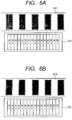
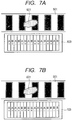
- FIG. 5 is a diagram for illustrating a relationship between the light receiver 103 and reflected light 501 reflected by the track pattern 201.
- the width for the four photodiodes included in the light receiver 103 in the X direction corresponds to one cycle of the pattern of the reflected light 501 reflected by the track pattern 201.
- the respective photodiodes 401 to 416 When the light emitted from the light emitter 101 and reflected by the track pattern 201 is received by the light receiver 103, the respective photodiodes 401 to 416 output voltage signals sig01 to sig16 obtained by converting photo-electric currents corresponding to amounts of the received light into a voltage by a current-voltage converter.
- the voltage signal sig01 can be expressed by a phase ⁇ corresponding to the cycle of the track pattern 201 as follows.
- sig 01 a 1 ⁇ sin ⁇ ⁇ + s 1
- a1 and s1 represent an amplitude and an offset, respectively.
- the voltage signal sig02 can be expressed as follows.
- the voltage signals sig03 to sig16 can be expressed as follows.
- the generating unit 104 When the switchover is made to the generation of the periodic signal by the switcher 105, as illustrated in FIG. 6A , the generating unit 104 generates a periodic signal A1 and a periodic signal B1 from the voltage signals sig01 to sigl6 output from the light receiver 103 as expressed by the following expressions.
- the periodic signals A1 and B1 are generated so that a voltage is amplified for the track pattern 201, and it is possible to generate the periodic signals A1 and B1 of the track pattern 201 whose phase are shifted from each other by 90°.
- the generating unit 104 When the switchover is made to the generation of the abnormality detection signal by the switcher 105, as illustrated in FIG. 6B , the generating unit 104 generates an abnormality detection signal A2 and an abnormality detection signal B2 from the voltage signals sig01 to sig16 output from the light receiver 103 as expressed by the following expressions.
- the abnormality detection signals A2 and B2 can be generated so that voltages cancel each other for the track pattern 201, and it is possible to generate the abnormality detection signals that are contrast with s2 irrespective of the phase ⁇ .
- e1 to e5 represent effects of the dust on the signals.
- abnormality detection signals A2 and B2 are expressed as follows.
- B 2 a 2 ⁇ sig 05 + sig 06 + sig 07 + sig 08 ⁇ sig 13 ⁇ sig 14 ⁇ sig 15 ⁇ sig 16 +
- s 2 a 2 ⁇ e 1 + e 2 + e 3 + s 2
- FIG. 8 is a flowchart for illustrating the flow of the operation of the position detector.
- Step S801 processing starts and then proceeds to Step S802.
- Step S802 the obtaining unit 107 sets the switcher 105 so that the output signal to be output from the output unit 106 is switched over to the abnormality detection signal. Then, the processing proceeds to Step S803. Specifically, a signal of 3 V is applied to the switcher 105.
- Step S803 the obtaining unit 107 obtains the abnormality detection signals A2 and B2 from the output unit 106. Then, the processing proceeds to Step S804.
- Step S804 the obtaining unit 107 sets the switcher 105 so that the output signal to be output from the output unit 106 is switched over to the periodic signal. Then, the processing proceeds to Step S805. Specifically, a signal of 0 V is applied to the switcher 105.
- Step S805 the obtaining unit 107 obtains the periodic signals A1 and B1 from the output unit 106, and the position deriver 108 derives the position from the periodic signals A1 and B1. Then, the processing proceeds to Step S806.
- Step S806 the abnormality determiner 109 determines whether or not an abnormality exists in the signal output by the output unit 106 from the abnormality detection signals A2 and B2. When an abnormality exists, the processing proceeds to Step S807, and when an abnormality does not exist, the processing proceeds to Step S808.
- the abnormality determiner 109 determines that the state is normal when A2 ⁇ B2 ⁇ 1.5 V, and that an abnormality exists otherwise.
- Step S807 the notifier 110 notifies the abnormality to the user. Then, the processing proceeds to Step S808. Specifically, the LED for abnormality notification is turned on.
- the position detector can detect an abnormality in the encoder 10, and notify the abnormality to the user.
- the abnormality detection signals A2 and B2 are generated by the encoder 10, to thereby allow the position detector to detect an abnormality in the encoder 10.
- the amplitudes of the abnormality detection signals A2 and B2 are smaller than those of the periodic signals A1 and B1, and hence when the abnormality detection signal is output, a gain may be increased to facilitate the detection of the effect of the dust.
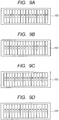
- the generation of the abnormality detection signal is not limited to the method according to this embodiment, and as exemplified in FIG. 9A, FIG. 9B ,
- FIG. 9C, and FIG. 9D the signal that is constant irrespective of the phase ⁇ only needs to be generated.
- FIG. 10 is a configuration block diagram of the position detector according to the second embodiment of the present invention.
- the same components as those of FIG. 1 serving as the configuration block diagram according to the first embodiment are denoted by the same reference numerals, and hence descriptions thereof are omitted.
- a scale 1002 has a track pattern that is different from that of the first embodiment and is obtained by multiplexing two kinds of track patterns. The details thereof are described later.
- a generating unit 1004 is a signal generating unit configured to generate the abnormality detection signal and two kinds of periodic signals that are generated from two kinds of track patterns multiplexed in the scale 1002 and that correspond to the respective track patterns.
- a switcher 1005 is a switcher configured to switch over among a first periodic signal, a second periodic signal, and the abnormality detection signal as a signal to be generated by the generating unit 1004.
- An abnormality determiner 1009 is an abnormality determiner configured to determine whether or not an abnormality exists in the encoder 10 based on the signal obtained by the obtaining unit 107. The abnormality determination conducted by the abnormality determiner 1009 is described later.
- a threshold memory 1011 is a memory configured to store a threshold value to be used by the abnormality determiner 1009 to determine that an abnormality exists, and is a non-volatile memory such as an EEPROM.
- a threshold generator 1012 is a generator configured to generate the threshold value to be stored in the threshold memory. Details thereof are described later.
- FIG. 11 is a plan view of the scale 1002.
- a track pattern 1101 of the scale 1002 is formed of two kinds of track patterns 1101a and 1101b that are arranged alternately.
- Reflective portions of the track pattern 1101a are formed at equal pitches P1, and the pitch P1 is determined so that thirty-nine reflective portions are formed over the total length Lmax of the scale, that is, to have thirty-nine cycles over the total length Lmax.
- the reflective portion of the track pattern 1101b are formed at equal pitches P2, and the pitch P2 is determined so that twenty reflective portions are formed over the total length Lmax of the scale, that is, to have twenty cycles over the total length Lmax.
- P2 and P1 have the following relationship.
- P 1 Lmax / 39
- ⁇ ⁇ P 1 / 20
- the light receiver 103 converts the reflected light reflected by the track pattern 1101 into the voltage signals sig01 to sig16.
- the voltage signal sig01 can be expressed as follows by using the phase ⁇ corresponding to the cycle of the track pattern 1101a and a phase ⁇ corresponding to the cycle of the track pattern 1101b.
- sig 01 a 1 ⁇ sin ⁇ + sin ⁇ + s 1
- the voltage signal sig02 can be expressed as follows.
- ⁇ represents a phase shift amount ascribable to the shift of P2 by ⁇ from double P1.
- sig 02 a 1 ⁇ cos ⁇ + sin ⁇ + 1 / 4 ⁇ ⁇ + s 1
- the voltage signals sig03 to sig16 can be expressed as follows.
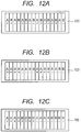
- the generating unit 1004 When the switchover is made to the generation of the first periodic signal by the switcher 1005, as illustrated in FIG. 12A , the generating unit 1004 generates a first periodic signal A1a and a first periodic signal B1a from the voltage signals sig01 to sig16 output from the light receiver 103 as expressed by the following expressions.
- the first periodic signals A1a and B1a can be generated so that the voltage is amplified for the track pattern 1101a and that the voltages cancel each other for the track pattern 1101b.
- the generating unit 1004 when the switchover is made to the generation of the second periodic signal by the switcher 1005, as illustrated in FIG. 12B , the generating unit 1004 generates a second periodic signal A1b and a second periodic signal B1b from the voltage signals sig01 to sig16 output from the light receiver 103 as expressed by the following expressions.
- the second periodic signals A1b and B1b can be generated so that the voltage is amplified for the track pattern 1101b and that the voltages cancel each other for the track pattern 1101a.
- the generating unit 1004 When the switchover is made to the generation of the abnormality detection signal by the switcher 1005, as illustrated in FIG. 12C , the generating unit 1004 generates the abnormality detection signal A2 and the abnormality detection signal B2 among the voltage signals sig01 to sig16 output from the light receiver 103 as expressed by the following expressions.
- the abnormality detection signals A2 and B2 can be generated so that the voltages cancel each other for the track patterns 1101a and 1101b, and the signal that is constant with s2 irrespective of the phases ⁇ and ⁇ can be generated.
- the effect on the signal due to the dust appears in the signal that is constant with s2 without an abnormality irrespective of the phases ⁇ and ⁇ , which allows the abnormality to be detected by using the abnormality detection signals A2 and B2.
- FIG. 13 is a flowchart for illustrating a flow of an operation of the threshold generator 1012. Note that, processing for the threshold value generation is assumed to be conducted when a product is produced, and is conducted when the threshold value generation is instructed through a switch (not shown) or the like.
- Step S1301 the processing starts and then proceeds to Step S1302.
- Step S1302 the obtaining unit 107 sets the switcher 1005 so that the output signal to be output from the output unit 106 is switched over to the abnormality detection signal. Then, the processing proceeds to Step S1303.
- Step S1303 initial values of threshold values maxA, minA, maxB, and minB are set to the present abnormality detection signals A2 and B2. Then, the processing proceeds to Step S1304.
- Step S1304 the abnormality detection signals are obtained again. Then, the processing proceeds to Step S1305.
- Step S1305 the threshold values maxA, minA, maxB, and minB are compared with the abnormality detection signals A2 and B2, and updated. Then, the processing proceeds to Step S1306.
- Step S1306 it is determined whether or not completion of the generation of the threshold value through the switch (not shown) or the like has been instructed. The processing proceeds to Step S1307 when the completion has been instructed, and returns to Step S1304 otherwise.
- Step S1307 it is determined whether or not the threshold values are appropriate.
- the processing proceeds to Step S1308, and when the threshold values are not appropriate, the processing proceeds to Step S1309. The determination as to whether or not the threshold values are appropriate is described later.
- Step S1308 the threshold values maxA, minA, maxB, and minB are stored in the non-volatile memory. Then, the processing proceeds to Step S1310.
- Step S1309 the abnormality is notified by the notifier 110. Then, the processing proceeds to Step S1310.
- Step S1310 the processing ends.
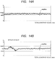
- FIG. 14A and FIG. 14B are graphs for showing the abnormality detection signal A2, in which the horizontal axis indicates a relative position of the movable member of the encoder with respect to the fixed member thereof, and the vertical axis indicates the voltage of the signal.
- a maximum value ampMax is a maximum value that can be taken by the amplitude of the abnormality detection signal A2 in a (normal) state in which there is no abnormality such as dust in design, and when an amplitude ampA of the abnormality detection signal A2 exceeds the maximum value ampMax, it is determined that the threshold value is not appropriate.
- FIG. 14A is a graph for showing the abnormality detection signal A2 in the state in which there is no abnormality such as dust, and as shown in the graph, the threshold values maxA and minA are derived by the threshold generator 1012.
- the maximum value ampMax can be guaranteed in design for the amplitude ampA including the noise amount with ampA ⁇ ampMax being satisfied in the state in which there is no abnormality such as dust, and hence it is determined that the threshold value is appropriate.
- FIG. 14B is a graph for showing the abnormality detection signal A2 subjected to the effect of an abnormality such as dust, and as shown in the graph, the threshold values maxA and minA are derived by the threshold generator 1012.
- FIG. 15 is a flowchart for illustrating the flow of the operation of the position detector.
- Step S1501 processing starts and then proceeds to Step S1502.
- Step S1502 the obtaining unit 107 sets the switcher 1005 so that the output signal to be output from the output unit 106 is switched over to the abnormality detection signal. Then, the processing proceeds to Step S1503.
- Step S1503 the obtaining unit 107 obtains the abnormality detection signals A2 and B2 from the output unit 106. Then, the processing proceeds to Step S1504.
- Step S1504 the obtaining unit 107 sets the switcher 1005 so that the output signal to be output from the output unit 106 is switched over to the first periodic signal. Then, the processing proceeds to Step S1505.
- Step S1505 the obtaining unit 107 obtains the first periodic signals A1a and B1a from the output unit 106. Then, the processing proceeds to Step S1506.
- Step S1506 the obtaining unit 107 sets the switcher 1005 so that the output signal to be output from the output unit 106 is switched over to the second periodic signal. Then, the processing proceeds to Step S1507.
- Step S1507 the obtaining unit 107 obtains the second periodic signals A1b and B1b from the output unit 106, and the position deriver 108 derives the position from the signals A1a, B1a, A1b, and B1b. Then, the processing proceeds to Step S1508.
- Step S1508 the abnormality determiner 1009 conducts the abnormality determination.
- the processing proceeds to Step S1509, and when an abnormality does not exist, the processing proceeds to Step S1510.
- the abnormality determiner 1009 is described later in detail.
- Step S1509 the position derived in Step S1507 is set as a provisional position. Then, the processing returns to Step S1502 in order to derive the position again.
- Step S1510 the position derived in Step S1507 is determined as an actual position. Then, the processing proceeds to Step S1511.
- Step S1511 the processing ends.
- FIG. 16A is a graph for showing the abnormality detection signal A2 in the state in which there is no abnormality such as dust.
- the horizontal axis indicates the relative position of the movable member of the encoder with respect to the fixed member thereof, and the vertical axis indicates the voltage of the signal.
- the threshold values maxA and minA are derived in the state in which there is no abnormality such as dust as shown in FIG. 14A
- a range N represents a range that falls out of the range of the threshold value, that is, a range in which the signal has a value larger than the threshold value maxA or smaller than the threshold value minA, and a range based on which the abnormality determiner 1009 determines that an abnormality exists.
- the graph of the abnormality detection signal B2 in the state in which there is no abnormality such as dust is the same as that of the abnormality detection signal A2 shown in FIG. 16A , and is therefore omitted.
- FIG. 16B and FIG. 16C are graphs for showing the abnormality detection signal A2 and the abnormality detection signal B2 in a state in which the effect of the abnormality such as dust is exerted.
- the abnormality detection signal A2 does not fall into the range N, and the abnormality determiner 1009 does not determine that an abnormality exists.
- the abnormality detection signals A2 and B2 fall into the range N, and the abnormality determiner 1009 can determine that an abnormality exists.
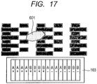
- the effect 601 of the dust or the like occurs in a range of the photodiodes 404 to 409.
- the effect of the dust does not appear in the abnormality detection signal A2, which is determined to be normal, while the effect of the dust appears in the abnormality detection signal B2, resulting in the determination that the abnormality exists.
- the periodic signal is adopted as the first signal that is for detecting the position, and the signal that does not change depending on a relative movement between the scale and the detector is adopted as the second signal that is for the abnormality detection.
- the present invention is not limited thereto.
- a signal having a value that changes within a first range, corresponding to a position of the scale relative to the detector, can be adopted as the first signal, and a signal having a value that does not change or changes in a second range smaller than the first range, corresponding to the position of the scale relative to the detector, can be adopted as the second signal.
- the abnormality detection signals A2 and B2 are generated by the encoder 10, to thereby allow the position detector to detect an abnormality in the encoder 10 even with two kinds of track patterns that are multiplexed.
- the position detector even with the track pattern obtained by multiplexing more patterns instead of two kinds of patterns, it can be determined that an abnormality exists by generating the abnormality detection signal that is constant irrespective of the phase.
- this embodiment exemplifies the case where, when it is determined that an abnormality exists, the abnormality is notified to the user and the position is derived again, but the present invention is not limited thereto.
- the position detector when the position detector includes a drive unit, there may be conducted a method of deriving the position again after driving to another position or a dust removal operation such as conducting drive at high speed, or applying vibrations, sending air toward the scale.
- a method of deriving the position again after driving to another position or a dust removal operation such as conducting drive at high speed, or applying vibrations, sending air toward the scale.
- a magnetic or electrostatic encoder may be used.
- a lens apparatus capable of exhibiting the effect of the present invention can be realized by applying the position detector of the embodiments to a lens apparatus including a movable optical member so as to detect the position of the movable optical member. Further, an image pickup apparatus capable of exhibiting the effect of the present invention can be realized by applying the position detector of the embodiments to an image pickup apparatus including a lens apparatus including a movable optical member and a camera apparatus so as to detect the position of the movable optical member.
- Embodiment(s) of the present invention can also be realized by a computer of a system or apparatus that reads out and executes computer executable instructions (e.g., one or more programs) recorded on a storage medium (which may also be referred to more fully as a 'non-transitory computer-readable storage medium') to perform the functions of one or more of the above-described embodiment(s) and/or that includes one or more circuits (e.g., application specific integrated circuit (ASIC)) for performing the functions of one or more of the above-described embodiment(s), and by a method performed by the computer of the system or apparatus by, for example, reading out and executing the computer executable instructions from the storage medium to perform the functions of one or more of the above-described embodiment(s) and/or controlling the one or more circuits to perform the functions of one or more of the above-described embodiment(s).
- computer executable instructions e.g., one or more programs
- a storage medium which may also be referred to more fully as
- the computer may comprise one or more processors (e.g., central processing unit (CPU), micro processing unit (MPU)) and may include a network of separate computers or separate processors to read out and execute the computer executable instructions.
- the computer executable instructions may be provided to the computer, for example, from a network or the storage medium.
- the storage medium may include, for example, one or more of a hard disk, a random-access memory (RAM), a read only memory (ROM), a storage of distributed computing systems, an optical disk (such as a compact disc (CD), digital versatile disc (DVD), or Blu-ray Disc (BD)TM), a flash memory device, a memory card, and the like.
Landscapes
- Physics & Mathematics (AREA)
- General Physics & Mathematics (AREA)
- Optical Transform (AREA)
- Transmission And Conversion Of Sensor Element Output (AREA)
Applications Claiming Priority (1)
| Application Number | Priority Date | Filing Date | Title |
|---|---|---|---|
| JP2014137473A JP6408804B2 (ja) | 2014-07-03 | 2014-07-03 | 位置検出装置及びそれを有するレンズ装置及び撮影装置 |
Publications (2)
| Publication Number | Publication Date |
|---|---|
| EP2963390A1 EP2963390A1 (en) | 2016-01-06 |
| EP2963390B1 true EP2963390B1 (en) | 2019-09-11 |
Family
ID=53491250
Family Applications (1)
| Application Number | Title | Priority Date | Filing Date |
|---|---|---|---|
| EP15001886.9A Active EP2963390B1 (en) | 2014-07-03 | 2015-06-25 | Position detector, and lens apparatus and image pickup apparatus including the position detector |
Country Status (3)
| Country | Link |
|---|---|
| US (1) | US9995603B2 (enExample) |
| EP (1) | EP2963390B1 (enExample) |
| JP (1) | JP6408804B2 (enExample) |
Families Citing this family (2)
| Publication number | Priority date | Publication date | Assignee | Title |
|---|---|---|---|---|
| JP6533360B2 (ja) * | 2013-10-30 | 2019-06-19 | キヤノン株式会社 | 位置検出装置及びそれを有するレンズ装置及び撮影装置 |
| US10615796B2 (en) * | 2016-07-29 | 2020-04-07 | Qualcomm Incorporated | Level shifter |
Family Cites Families (10)
| Publication number | Priority date | Publication date | Assignee | Title |
|---|---|---|---|---|
| JP2002039727A (ja) | 2000-07-21 | 2002-02-06 | Asahi Precision Co Ltd | アブソリュートエンコーダを備えた測角装置 |
| US6898744B1 (en) * | 2001-11-01 | 2005-05-24 | Louis J. Jannotta | Apparatus and methods for monitoring encoder signals |
| JP5887064B2 (ja) | 2010-04-28 | 2016-03-16 | 株式会社ミツトヨ | 光学式エンコーダ |
| US8493572B2 (en) * | 2010-05-05 | 2013-07-23 | Mitutoyo Corporation | Optical encoder having contamination and defect resistant signal processing |
| JP5375796B2 (ja) * | 2010-11-05 | 2013-12-25 | 株式会社デンソー | 回転角検出装置、および、これを用いた電動パワーステアリング装置 |
| JP5791340B2 (ja) * | 2011-04-14 | 2015-10-07 | キヤノン株式会社 | エンコーダ |
| EP2600113B1 (de) * | 2011-11-29 | 2018-01-10 | SICK STEGMANN GmbH | Verfahren und Vorrichtung zur Messung des Drehwinkels zweier relativ zueinander rotierender Objekte |
| JP5727958B2 (ja) * | 2012-03-19 | 2015-06-03 | 旭化成エレクトロニクス株式会社 | 磁場計測装置の異常検出装置 |
| JP6150462B2 (ja) * | 2012-05-02 | 2017-06-21 | キヤノン株式会社 | 位置検出エンコーダおよびこれを用いた装置 |
| JP6207208B2 (ja) * | 2013-04-12 | 2017-10-04 | キヤノン株式会社 | 位置検出手段 |
-
2014
- 2014-07-03 JP JP2014137473A patent/JP6408804B2/ja active Active
-
2015
- 2015-06-25 EP EP15001886.9A patent/EP2963390B1/en active Active
- 2015-06-30 US US14/754,895 patent/US9995603B2/en active Active
Non-Patent Citations (1)
| Title |
|---|
| None * |
Also Published As
| Publication number | Publication date |
|---|---|
| EP2963390A1 (en) | 2016-01-06 |
| US9995603B2 (en) | 2018-06-12 |
| US20160003644A1 (en) | 2016-01-07 |
| JP2016014620A (ja) | 2016-01-28 |
| JP6408804B2 (ja) | 2018-10-17 |
Similar Documents
| Publication | Publication Date | Title |
|---|---|---|
| US10540559B2 (en) | Position detection apparatus, lens apparatus, image pickup system, machine tool apparatus, position detection method, and non-transitory computer-readable storage medium which are capable of detecting abnormality | |
| KR101842259B1 (ko) | 이미지 센서 및 이를 포함하는 엑스-레이 이미지 센싱 모듈 | |
| US9200928B2 (en) | Position detector | |
| US20150115142A1 (en) | Position detecting apparatus, and lens apparatus and image pickup apparatus including the position detecting apparatus | |
| EP2963390B1 (en) | Position detector, and lens apparatus and image pickup apparatus including the position detector | |
| EP2889585B1 (en) | Encoder and encoding method for slip ring | |
| US20150130931A1 (en) | Position detecting apparatus, and lens apparatus and image pickup apparatus including the position detecting apparatus | |
| US10158780B2 (en) | Image forming apparatus and optical sensor detecting target formed on image carrier or recording medium | |
| US10067340B2 (en) | Method for determining phase of rotating polygonal mirror used in image forming apparatus | |
| US9103699B2 (en) | Encoder and apparatus using the same | |
| US8934114B2 (en) | Image processing apparatus, image processing method, and program | |
| US9606243B2 (en) | Radiation imaging apparatus, method of determining radiation irradiation, and storage medium | |
| US10078288B2 (en) | Image forming apparatus that scans photosensitive member by using rotating polygonal mirror | |
| KR20140134529A (ko) | 촬상 장치 및 제어 방법 | |
| US9470880B2 (en) | Position detecting apparatus, and lens apparatus and optical operating apparatus including the position detecting apparatus | |
| US9435667B2 (en) | Position detecting apparatus, and lens apparatus and image pickup apparatus including the position detecting apparatus | |
| JP6466642B2 (ja) | エンコーダ | |
| US10393550B2 (en) | Encoder and apparatus having the same | |
| US9383230B2 (en) | Position detection apparatus, lens apparatus, image pickup system, machine tool apparatus, position detection method, and non-transitory computer-readable storage medium | |
| US20160321810A1 (en) | Optical navigation sensor, electronic device with optical navigation function and operation method thereof | |
| JP2016151676A5 (enExample) | ||
| US10579007B2 (en) | Image forming apparatus for executing color registration adjustment | |
| US10914577B2 (en) | Position detecting apparatus, lens apparatus, position detecting method, and storage medium | |
| JP2005017000A (ja) | エンコーダ | |
| JP2019113476A (ja) | 磁気検出装置 |
Legal Events
| Date | Code | Title | Description |
|---|---|---|---|
| PUAI | Public reference made under article 153(3) epc to a published international application that has entered the european phase |
Free format text: ORIGINAL CODE: 0009012 |
|
| AK | Designated contracting states |
Kind code of ref document: A1 Designated state(s): AL AT BE BG CH CY CZ DE DK EE ES FI FR GB GR HR HU IE IS IT LI LT LU LV MC MK MT NL NO PL PT RO RS SE SI SK SM TR |
|
| AX | Request for extension of the european patent |
Extension state: BA ME |
|
| 17P | Request for examination filed |
Effective date: 20160706 |
|
| RBV | Designated contracting states (corrected) |
Designated state(s): AL AT BE BG CH CY CZ DE DK EE ES FI FR GB GR HR HU IE IS IT LI LT LU LV MC MK MT NL NO PL PT RO RS SE SI SK SM TR |
|
| GRAP | Despatch of communication of intention to grant a patent |
Free format text: ORIGINAL CODE: EPIDOSNIGR1 |
|
| STAA | Information on the status of an ep patent application or granted ep patent |
Free format text: STATUS: GRANT OF PATENT IS INTENDED |
|
| INTG | Intention to grant announced |
Effective date: 20180403 |
|
| RIN1 | Information on inventor provided before grant (corrected) |
Inventor name: YONEZAWA, TAKESHI |
|
| GRAJ | Information related to disapproval of communication of intention to grant by the applicant or resumption of examination proceedings by the epo deleted |
Free format text: ORIGINAL CODE: EPIDOSDIGR1 |
|
| STAA | Information on the status of an ep patent application or granted ep patent |
Free format text: STATUS: REQUEST FOR EXAMINATION WAS MADE |
|
| INTC | Intention to grant announced (deleted) | ||
| STAA | Information on the status of an ep patent application or granted ep patent |
Free format text: STATUS: EXAMINATION IS IN PROGRESS |
|
| 17Q | First examination report despatched |
Effective date: 20180918 |
|
| GRAP | Despatch of communication of intention to grant a patent |
Free format text: ORIGINAL CODE: EPIDOSNIGR1 |
|
| STAA | Information on the status of an ep patent application or granted ep patent |
Free format text: STATUS: GRANT OF PATENT IS INTENDED |
|
| INTG | Intention to grant announced |
Effective date: 20181221 |
|
| GRAS | Grant fee paid |
Free format text: ORIGINAL CODE: EPIDOSNIGR3 |
|
| RAP1 | Party data changed (applicant data changed or rights of an application transferred) |
Owner name: CANON KABUSHIKI KAISHA |
|
| GRAA | (expected) grant |
Free format text: ORIGINAL CODE: 0009210 |
|
| STAA | Information on the status of an ep patent application or granted ep patent |
Free format text: STATUS: THE PATENT HAS BEEN GRANTED |
|
| AK | Designated contracting states |
Kind code of ref document: B1 Designated state(s): AL AT BE BG CH CY CZ DE DK EE ES FI FR GB GR HR HU IE IS IT LI LT LU LV MC MK MT NL NO PL PT RO RS SE SI SK SM TR |
|
| REG | Reference to a national code |
Ref country code: GB Ref legal event code: FG4D |
|
| REG | Reference to a national code |
Ref country code: CH Ref legal event code: EP |
|
| REG | Reference to a national code |
Ref country code: AT Ref legal event code: REF Ref document number: 1179027 Country of ref document: AT Kind code of ref document: T Effective date: 20190915 |
|
| REG | Reference to a national code |
Ref country code: DE Ref legal event code: R096 Ref document number: 602015037583 Country of ref document: DE Ref country code: IE Ref legal event code: FG4D |
|
| REG | Reference to a national code |
Ref country code: NL Ref legal event code: MP Effective date: 20190911 |
|
| REG | Reference to a national code |
Ref country code: LT Ref legal event code: MG4D |
|
| PG25 | Lapsed in a contracting state [announced via postgrant information from national office to epo] |
Ref country code: NO Free format text: LAPSE BECAUSE OF FAILURE TO SUBMIT A TRANSLATION OF THE DESCRIPTION OR TO PAY THE FEE WITHIN THE PRESCRIBED TIME-LIMIT Effective date: 20191211 Ref country code: SE Free format text: LAPSE BECAUSE OF FAILURE TO SUBMIT A TRANSLATION OF THE DESCRIPTION OR TO PAY THE FEE WITHIN THE PRESCRIBED TIME-LIMIT Effective date: 20190911 Ref country code: FI Free format text: LAPSE BECAUSE OF FAILURE TO SUBMIT A TRANSLATION OF THE DESCRIPTION OR TO PAY THE FEE WITHIN THE PRESCRIBED TIME-LIMIT Effective date: 20190911 Ref country code: HR Free format text: LAPSE BECAUSE OF FAILURE TO SUBMIT A TRANSLATION OF THE DESCRIPTION OR TO PAY THE FEE WITHIN THE PRESCRIBED TIME-LIMIT Effective date: 20190911 Ref country code: LT Free format text: LAPSE BECAUSE OF FAILURE TO SUBMIT A TRANSLATION OF THE DESCRIPTION OR TO PAY THE FEE WITHIN THE PRESCRIBED TIME-LIMIT Effective date: 20190911 Ref country code: BG Free format text: LAPSE BECAUSE OF FAILURE TO SUBMIT A TRANSLATION OF THE DESCRIPTION OR TO PAY THE FEE WITHIN THE PRESCRIBED TIME-LIMIT Effective date: 20191211 |
|
| PG25 | Lapsed in a contracting state [announced via postgrant information from national office to epo] |
Ref country code: ES Free format text: LAPSE BECAUSE OF FAILURE TO SUBMIT A TRANSLATION OF THE DESCRIPTION OR TO PAY THE FEE WITHIN THE PRESCRIBED TIME-LIMIT Effective date: 20190911 Ref country code: AL Free format text: LAPSE BECAUSE OF FAILURE TO SUBMIT A TRANSLATION OF THE DESCRIPTION OR TO PAY THE FEE WITHIN THE PRESCRIBED TIME-LIMIT Effective date: 20190911 Ref country code: LV Free format text: LAPSE BECAUSE OF FAILURE TO SUBMIT A TRANSLATION OF THE DESCRIPTION OR TO PAY THE FEE WITHIN THE PRESCRIBED TIME-LIMIT Effective date: 20190911 Ref country code: RS Free format text: LAPSE BECAUSE OF FAILURE TO SUBMIT A TRANSLATION OF THE DESCRIPTION OR TO PAY THE FEE WITHIN THE PRESCRIBED TIME-LIMIT Effective date: 20190911 Ref country code: GR Free format text: LAPSE BECAUSE OF FAILURE TO SUBMIT A TRANSLATION OF THE DESCRIPTION OR TO PAY THE FEE WITHIN THE PRESCRIBED TIME-LIMIT Effective date: 20191212 |
|
| REG | Reference to a national code |
Ref country code: AT Ref legal event code: MK05 Ref document number: 1179027 Country of ref document: AT Kind code of ref document: T Effective date: 20190911 |
|
| PG25 | Lapsed in a contracting state [announced via postgrant information from national office to epo] |
Ref country code: RO Free format text: LAPSE BECAUSE OF FAILURE TO SUBMIT A TRANSLATION OF THE DESCRIPTION OR TO PAY THE FEE WITHIN THE PRESCRIBED TIME-LIMIT Effective date: 20190911 Ref country code: PT Free format text: LAPSE BECAUSE OF FAILURE TO SUBMIT A TRANSLATION OF THE DESCRIPTION OR TO PAY THE FEE WITHIN THE PRESCRIBED TIME-LIMIT Effective date: 20200113 Ref country code: EE Free format text: LAPSE BECAUSE OF FAILURE TO SUBMIT A TRANSLATION OF THE DESCRIPTION OR TO PAY THE FEE WITHIN THE PRESCRIBED TIME-LIMIT Effective date: 20190911 Ref country code: PL Free format text: LAPSE BECAUSE OF FAILURE TO SUBMIT A TRANSLATION OF THE DESCRIPTION OR TO PAY THE FEE WITHIN THE PRESCRIBED TIME-LIMIT Effective date: 20190911 Ref country code: NL Free format text: LAPSE BECAUSE OF FAILURE TO SUBMIT A TRANSLATION OF THE DESCRIPTION OR TO PAY THE FEE WITHIN THE PRESCRIBED TIME-LIMIT Effective date: 20190911 Ref country code: AT Free format text: LAPSE BECAUSE OF FAILURE TO SUBMIT A TRANSLATION OF THE DESCRIPTION OR TO PAY THE FEE WITHIN THE PRESCRIBED TIME-LIMIT Effective date: 20190911 Ref country code: IT Free format text: LAPSE BECAUSE OF FAILURE TO SUBMIT A TRANSLATION OF THE DESCRIPTION OR TO PAY THE FEE WITHIN THE PRESCRIBED TIME-LIMIT Effective date: 20190911 |
|
| PG25 | Lapsed in a contracting state [announced via postgrant information from national office to epo] |
Ref country code: IS Free format text: LAPSE BECAUSE OF FAILURE TO SUBMIT A TRANSLATION OF THE DESCRIPTION OR TO PAY THE FEE WITHIN THE PRESCRIBED TIME-LIMIT Effective date: 20200224 Ref country code: CZ Free format text: LAPSE BECAUSE OF FAILURE TO SUBMIT A TRANSLATION OF THE DESCRIPTION OR TO PAY THE FEE WITHIN THE PRESCRIBED TIME-LIMIT Effective date: 20190911 Ref country code: SM Free format text: LAPSE BECAUSE OF FAILURE TO SUBMIT A TRANSLATION OF THE DESCRIPTION OR TO PAY THE FEE WITHIN THE PRESCRIBED TIME-LIMIT Effective date: 20190911 Ref country code: SK Free format text: LAPSE BECAUSE OF FAILURE TO SUBMIT A TRANSLATION OF THE DESCRIPTION OR TO PAY THE FEE WITHIN THE PRESCRIBED TIME-LIMIT Effective date: 20190911 |
|
| REG | Reference to a national code |
Ref country code: DE Ref legal event code: R097 Ref document number: 602015037583 Country of ref document: DE |
|
| PLBE | No opposition filed within time limit |
Free format text: ORIGINAL CODE: 0009261 |
|
| STAA | Information on the status of an ep patent application or granted ep patent |
Free format text: STATUS: NO OPPOSITION FILED WITHIN TIME LIMIT |
|
| PG2D | Information on lapse in contracting state deleted |
Ref country code: IS |
|
| PG25 | Lapsed in a contracting state [announced via postgrant information from national office to epo] |
Ref country code: DK Free format text: LAPSE BECAUSE OF FAILURE TO SUBMIT A TRANSLATION OF THE DESCRIPTION OR TO PAY THE FEE WITHIN THE PRESCRIBED TIME-LIMIT Effective date: 20190911 Ref country code: IS Free format text: LAPSE BECAUSE OF FAILURE TO SUBMIT A TRANSLATION OF THE DESCRIPTION OR TO PAY THE FEE WITHIN THE PRESCRIBED TIME-LIMIT Effective date: 20200112 |
|
| 26N | No opposition filed |
Effective date: 20200615 |
|
| PG25 | Lapsed in a contracting state [announced via postgrant information from national office to epo] |
Ref country code: SI Free format text: LAPSE BECAUSE OF FAILURE TO SUBMIT A TRANSLATION OF THE DESCRIPTION OR TO PAY THE FEE WITHIN THE PRESCRIBED TIME-LIMIT Effective date: 20190911 |
|
| PG25 | Lapsed in a contracting state [announced via postgrant information from national office to epo] |
Ref country code: MC Free format text: LAPSE BECAUSE OF FAILURE TO SUBMIT A TRANSLATION OF THE DESCRIPTION OR TO PAY THE FEE WITHIN THE PRESCRIBED TIME-LIMIT Effective date: 20190911 |
|
| REG | Reference to a national code |
Ref country code: CH Ref legal event code: PL |
|
| PG25 | Lapsed in a contracting state [announced via postgrant information from national office to epo] |
Ref country code: LU Free format text: LAPSE BECAUSE OF NON-PAYMENT OF DUE FEES Effective date: 20200625 |
|
| REG | Reference to a national code |
Ref country code: BE Ref legal event code: MM Effective date: 20200630 |
|
| PG25 | Lapsed in a contracting state [announced via postgrant information from national office to epo] |
Ref country code: IE Free format text: LAPSE BECAUSE OF NON-PAYMENT OF DUE FEES Effective date: 20200625 Ref country code: CH Free format text: LAPSE BECAUSE OF NON-PAYMENT OF DUE FEES Effective date: 20200630 Ref country code: LI Free format text: LAPSE BECAUSE OF NON-PAYMENT OF DUE FEES Effective date: 20200630 |
|
| PG25 | Lapsed in a contracting state [announced via postgrant information from national office to epo] |
Ref country code: BE Free format text: LAPSE BECAUSE OF NON-PAYMENT OF DUE FEES Effective date: 20200630 |
|
| PG25 | Lapsed in a contracting state [announced via postgrant information from national office to epo] |
Ref country code: TR Free format text: LAPSE BECAUSE OF FAILURE TO SUBMIT A TRANSLATION OF THE DESCRIPTION OR TO PAY THE FEE WITHIN THE PRESCRIBED TIME-LIMIT Effective date: 20190911 Ref country code: MT Free format text: LAPSE BECAUSE OF FAILURE TO SUBMIT A TRANSLATION OF THE DESCRIPTION OR TO PAY THE FEE WITHIN THE PRESCRIBED TIME-LIMIT Effective date: 20190911 Ref country code: CY Free format text: LAPSE BECAUSE OF FAILURE TO SUBMIT A TRANSLATION OF THE DESCRIPTION OR TO PAY THE FEE WITHIN THE PRESCRIBED TIME-LIMIT Effective date: 20190911 |
|
| PG25 | Lapsed in a contracting state [announced via postgrant information from national office to epo] |
Ref country code: MK Free format text: LAPSE BECAUSE OF FAILURE TO SUBMIT A TRANSLATION OF THE DESCRIPTION OR TO PAY THE FEE WITHIN THE PRESCRIBED TIME-LIMIT Effective date: 20190911 |
|
| PGFP | Annual fee paid to national office [announced via postgrant information from national office to epo] |
Ref country code: DE Payment date: 20250520 Year of fee payment: 11 |
|
| PGFP | Annual fee paid to national office [announced via postgrant information from national office to epo] |
Ref country code: GB Payment date: 20250520 Year of fee payment: 11 |
|
| PGFP | Annual fee paid to national office [announced via postgrant information from national office to epo] |
Ref country code: FR Payment date: 20250521 Year of fee payment: 11 |