EP2962721B1 - Gaine pour voie d'abord étanche par un vaisseau - Google Patents
Gaine pour voie d'abord étanche par un vaisseau Download PDFInfo
- Publication number
- EP2962721B1 EP2962721B1 EP14175797.1A EP14175797A EP2962721B1 EP 2962721 B1 EP2962721 B1 EP 2962721B1 EP 14175797 A EP14175797 A EP 14175797A EP 2962721 B1 EP2962721 B1 EP 2962721B1
- Authority
- EP
- European Patent Office
- Prior art keywords
- sheath
- vessel
- base
- proximal end
- expansion device
- Prior art date
- Legal status (The legal status is an assumption and is not a legal conclusion. Google has not performed a legal analysis and makes no representation as to the accuracy of the status listed.)
- Active
Links
- 239000008280 blood Substances 0.000 claims description 6
- 210000004369 blood Anatomy 0.000 claims description 6
- 230000036772 blood pressure Effects 0.000 claims description 6
- 230000002439 hemostatic effect Effects 0.000 claims description 6
- 241001465754 Metazoa Species 0.000 claims description 4
- 238000003780 insertion Methods 0.000 description 13
- 230000037431 insertion Effects 0.000 description 13
- 210000001367 artery Anatomy 0.000 description 7
- 238000000034 method Methods 0.000 description 7
- 230000017531 blood circulation Effects 0.000 description 6
- 230000001965 increasing effect Effects 0.000 description 6
- 239000000463 material Substances 0.000 description 5
- 208000032843 Hemorrhage Diseases 0.000 description 4
- 208000027418 Wounds and injury Diseases 0.000 description 4
- 230000000740 bleeding effect Effects 0.000 description 4
- 230000023597 hemostasis Effects 0.000 description 4
- 210000004204 blood vessel Anatomy 0.000 description 3
- 230000000747 cardiac effect Effects 0.000 description 3
- 230000004087 circulation Effects 0.000 description 3
- 210000000709 aorta Anatomy 0.000 description 2
- 238000011109 contamination Methods 0.000 description 2
- 238000013461 design Methods 0.000 description 2
- 238000006073 displacement reaction Methods 0.000 description 2
- 210000005240 left ventricle Anatomy 0.000 description 2
- 238000005259 measurement Methods 0.000 description 2
- 230000035515 penetration Effects 0.000 description 2
- 239000000126 substance Substances 0.000 description 2
- 230000008961 swelling Effects 0.000 description 2
- 210000001519 tissue Anatomy 0.000 description 2
- 230000000472 traumatic effect Effects 0.000 description 2
- 230000002792 vascular Effects 0.000 description 2
- 206010018852 Haematoma Diseases 0.000 description 1
- 206010033799 Paralysis Diseases 0.000 description 1
- 208000031481 Pathologic Constriction Diseases 0.000 description 1
- 208000007536 Thrombosis Diseases 0.000 description 1
- 210000000577 adipose tissue Anatomy 0.000 description 1
- 210000001765 aortic valve Anatomy 0.000 description 1
- 244000052616 bacterial pathogen Species 0.000 description 1
- 230000004888 barrier function Effects 0.000 description 1
- 238000005452 bending Methods 0.000 description 1
- 210000005242 cardiac chamber Anatomy 0.000 description 1
- 230000002612 cardiopulmonary effect Effects 0.000 description 1
- 230000006835 compression Effects 0.000 description 1
- 238000007906 compression Methods 0.000 description 1
- 238000007887 coronary angioplasty Methods 0.000 description 1
- 230000001419 dependent effect Effects 0.000 description 1
- 238000011161 development Methods 0.000 description 1
- 230000018109 developmental process Effects 0.000 description 1
- 238000002405 diagnostic procedure Methods 0.000 description 1
- 230000010339 dilation Effects 0.000 description 1
- 210000001105 femoral artery Anatomy 0.000 description 1
- 239000012530 fluid Substances 0.000 description 1
- 230000001939 inductive effect Effects 0.000 description 1
- 230000036512 infertility Effects 0.000 description 1
- 208000014674 injury Diseases 0.000 description 1
- 238000004519 manufacturing process Methods 0.000 description 1
- 208000021090 palsy Diseases 0.000 description 1
- 244000052769 pathogen Species 0.000 description 1
- 230000010412 perfusion Effects 0.000 description 1
- 238000007789 sealing Methods 0.000 description 1
- 230000036262 stenosis Effects 0.000 description 1
- 208000037804 stenosis Diseases 0.000 description 1
- 238000007920 subcutaneous administration Methods 0.000 description 1
- 238000001356 surgical procedure Methods 0.000 description 1
- 230000007704 transition Effects 0.000 description 1
- 230000008733 trauma Effects 0.000 description 1
- 210000003462 vein Anatomy 0.000 description 1
Images


Classifications
-
- A—HUMAN NECESSITIES
- A61—MEDICAL OR VETERINARY SCIENCE; HYGIENE
- A61M—DEVICES FOR INTRODUCING MEDIA INTO, OR ONTO, THE BODY; DEVICES FOR TRANSDUCING BODY MEDIA OR FOR TAKING MEDIA FROM THE BODY; DEVICES FOR PRODUCING OR ENDING SLEEP OR STUPOR
- A61M39/00—Tubes, tube connectors, tube couplings, valves, access sites or the like, specially adapted for medical use
- A61M39/02—Access sites
- A61M39/0247—Semi-permanent or permanent transcutaneous or percutaneous access sites to the inside of the body
-
- A—HUMAN NECESSITIES
- A61—MEDICAL OR VETERINARY SCIENCE; HYGIENE
- A61M—DEVICES FOR INTRODUCING MEDIA INTO, OR ONTO, THE BODY; DEVICES FOR TRANSDUCING BODY MEDIA OR FOR TAKING MEDIA FROM THE BODY; DEVICES FOR PRODUCING OR ENDING SLEEP OR STUPOR
- A61M39/00—Tubes, tube connectors, tube couplings, valves, access sites or the like, specially adapted for medical use
- A61M39/02—Access sites
-
- A—HUMAN NECESSITIES
- A61—MEDICAL OR VETERINARY SCIENCE; HYGIENE
- A61B—DIAGNOSIS; SURGERY; IDENTIFICATION
- A61B5/00—Measuring for diagnostic purposes; Identification of persons
- A61B5/02—Detecting, measuring or recording pulse, heart rate, blood pressure or blood flow; Combined pulse/heart-rate/blood pressure determination; Evaluating a cardiovascular condition not otherwise provided for, e.g. using combinations of techniques provided for in this group with electrocardiography or electroauscultation; Heart catheters for measuring blood pressure
- A61B5/021—Measuring pressure in heart or blood vessels
- A61B5/0215—Measuring pressure in heart or blood vessels by means inserted into the body
-
- A—HUMAN NECESSITIES
- A61—MEDICAL OR VETERINARY SCIENCE; HYGIENE
- A61M—DEVICES FOR INTRODUCING MEDIA INTO, OR ONTO, THE BODY; DEVICES FOR TRANSDUCING BODY MEDIA OR FOR TAKING MEDIA FROM THE BODY; DEVICES FOR PRODUCING OR ENDING SLEEP OR STUPOR
- A61M39/00—Tubes, tube connectors, tube couplings, valves, access sites or the like, specially adapted for medical use
- A61M39/02—Access sites
- A61M39/06—Haemostasis valves, i.e. gaskets sealing around a needle, catheter or the like, closing on removal thereof
-
- A—HUMAN NECESSITIES
- A61—MEDICAL OR VETERINARY SCIENCE; HYGIENE
- A61M—DEVICES FOR INTRODUCING MEDIA INTO, OR ONTO, THE BODY; DEVICES FOR TRANSDUCING BODY MEDIA OR FOR TAKING MEDIA FROM THE BODY; DEVICES FOR PRODUCING OR ENDING SLEEP OR STUPOR
- A61M60/00—Blood pumps; Devices for mechanical circulatory actuation; Balloon pumps for circulatory assistance
- A61M60/10—Location thereof with respect to the patient's body
- A61M60/122—Implantable pumps or pumping devices, i.e. the blood being pumped inside the patient's body
- A61M60/126—Implantable pumps or pumping devices, i.e. the blood being pumped inside the patient's body implantable via, into, inside, in line, branching on, or around a blood vessel
- A61M60/13—Implantable pumps or pumping devices, i.e. the blood being pumped inside the patient's body implantable via, into, inside, in line, branching on, or around a blood vessel by means of a catheter allowing explantation, e.g. catheter pumps temporarily introduced via the vascular system
-
- A—HUMAN NECESSITIES
- A61—MEDICAL OR VETERINARY SCIENCE; HYGIENE
- A61M—DEVICES FOR INTRODUCING MEDIA INTO, OR ONTO, THE BODY; DEVICES FOR TRANSDUCING BODY MEDIA OR FOR TAKING MEDIA FROM THE BODY; DEVICES FOR PRODUCING OR ENDING SLEEP OR STUPOR
- A61M60/00—Blood pumps; Devices for mechanical circulatory actuation; Balloon pumps for circulatory assistance
- A61M60/10—Location thereof with respect to the patient's body
- A61M60/122—Implantable pumps or pumping devices, i.e. the blood being pumped inside the patient's body
- A61M60/126—Implantable pumps or pumping devices, i.e. the blood being pumped inside the patient's body implantable via, into, inside, in line, branching on, or around a blood vessel
- A61M60/148—Implantable pumps or pumping devices, i.e. the blood being pumped inside the patient's body implantable via, into, inside, in line, branching on, or around a blood vessel in line with a blood vessel using resection or like techniques, e.g. permanent endovascular heart assist devices
-
- A—HUMAN NECESSITIES
- A61—MEDICAL OR VETERINARY SCIENCE; HYGIENE
- A61M—DEVICES FOR INTRODUCING MEDIA INTO, OR ONTO, THE BODY; DEVICES FOR TRANSDUCING BODY MEDIA OR FOR TAKING MEDIA FROM THE BODY; DEVICES FOR PRODUCING OR ENDING SLEEP OR STUPOR
- A61M60/00—Blood pumps; Devices for mechanical circulatory actuation; Balloon pumps for circulatory assistance
- A61M60/20—Type thereof
- A61M60/205—Non-positive displacement blood pumps
- A61M60/216—Non-positive displacement blood pumps including a rotating member acting on the blood, e.g. impeller
-
- A—HUMAN NECESSITIES
- A61—MEDICAL OR VETERINARY SCIENCE; HYGIENE
- A61M—DEVICES FOR INTRODUCING MEDIA INTO, OR ONTO, THE BODY; DEVICES FOR TRANSDUCING BODY MEDIA OR FOR TAKING MEDIA FROM THE BODY; DEVICES FOR PRODUCING OR ENDING SLEEP OR STUPOR
- A61M60/00—Blood pumps; Devices for mechanical circulatory actuation; Balloon pumps for circulatory assistance
- A61M60/80—Constructional details other than related to driving
- A61M60/855—Constructional details other than related to driving of implantable pumps or pumping devices
- A61M60/865—Devices for guiding or inserting pumps or pumping devices into the patient's body
-
- A—HUMAN NECESSITIES
- A61—MEDICAL OR VETERINARY SCIENCE; HYGIENE
- A61M—DEVICES FOR INTRODUCING MEDIA INTO, OR ONTO, THE BODY; DEVICES FOR TRANSDUCING BODY MEDIA OR FOR TAKING MEDIA FROM THE BODY; DEVICES FOR PRODUCING OR ENDING SLEEP OR STUPOR
- A61M39/00—Tubes, tube connectors, tube couplings, valves, access sites or the like, specially adapted for medical use
- A61M39/02—Access sites
- A61M39/0247—Semi-permanent or permanent transcutaneous or percutaneous access sites to the inside of the body
- A61M2039/0258—Semi-permanent or permanent transcutaneous or percutaneous access sites to the inside of the body for vascular access, e.g. blood stream access
-
- A—HUMAN NECESSITIES
- A61—MEDICAL OR VETERINARY SCIENCE; HYGIENE
- A61M—DEVICES FOR INTRODUCING MEDIA INTO, OR ONTO, THE BODY; DEVICES FOR TRANSDUCING BODY MEDIA OR FOR TAKING MEDIA FROM THE BODY; DEVICES FOR PRODUCING OR ENDING SLEEP OR STUPOR
- A61M39/00—Tubes, tube connectors, tube couplings, valves, access sites or the like, specially adapted for medical use
- A61M39/02—Access sites
- A61M39/0247—Semi-permanent or permanent transcutaneous or percutaneous access sites to the inside of the body
- A61M2039/0267—Semi-permanent or permanent transcutaneous or percutaneous access sites to the inside of the body comprising sensors or electrical contacts
-
- A—HUMAN NECESSITIES
- A61—MEDICAL OR VETERINARY SCIENCE; HYGIENE
- A61M—DEVICES FOR INTRODUCING MEDIA INTO, OR ONTO, THE BODY; DEVICES FOR TRANSDUCING BODY MEDIA OR FOR TAKING MEDIA FROM THE BODY; DEVICES FOR PRODUCING OR ENDING SLEEP OR STUPOR
- A61M39/00—Tubes, tube connectors, tube couplings, valves, access sites or the like, specially adapted for medical use
- A61M39/02—Access sites
- A61M39/0247—Semi-permanent or permanent transcutaneous or percutaneous access sites to the inside of the body
- A61M2039/0273—Semi-permanent or permanent transcutaneous or percutaneous access sites to the inside of the body for introducing catheters into the body
-
- A—HUMAN NECESSITIES
- A61—MEDICAL OR VETERINARY SCIENCE; HYGIENE
- A61M—DEVICES FOR INTRODUCING MEDIA INTO, OR ONTO, THE BODY; DEVICES FOR TRANSDUCING BODY MEDIA OR FOR TAKING MEDIA FROM THE BODY; DEVICES FOR PRODUCING OR ENDING SLEEP OR STUPOR
- A61M39/00—Tubes, tube connectors, tube couplings, valves, access sites or the like, specially adapted for medical use
- A61M39/02—Access sites
- A61M39/0247—Semi-permanent or permanent transcutaneous or percutaneous access sites to the inside of the body
- A61M2039/0279—Semi-permanent or permanent transcutaneous or percutaneous access sites to the inside of the body for introducing medical instruments into the body, e.g. endoscope, surgical tools
-
- A—HUMAN NECESSITIES
- A61—MEDICAL OR VETERINARY SCIENCE; HYGIENE
- A61M—DEVICES FOR INTRODUCING MEDIA INTO, OR ONTO, THE BODY; DEVICES FOR TRANSDUCING BODY MEDIA OR FOR TAKING MEDIA FROM THE BODY; DEVICES FOR PRODUCING OR ENDING SLEEP OR STUPOR
- A61M39/00—Tubes, tube connectors, tube couplings, valves, access sites or the like, specially adapted for medical use
- A61M39/02—Access sites
- A61M39/0247—Semi-permanent or permanent transcutaneous or percutaneous access sites to the inside of the body
- A61M2039/0297—Semi-permanent or permanent transcutaneous or percutaneous access sites to the inside of the body at least part of it being inflatable, e.g. for anchoring, sealing or removing
-
- A—HUMAN NECESSITIES
- A61—MEDICAL OR VETERINARY SCIENCE; HYGIENE
- A61M—DEVICES FOR INTRODUCING MEDIA INTO, OR ONTO, THE BODY; DEVICES FOR TRANSDUCING BODY MEDIA OR FOR TAKING MEDIA FROM THE BODY; DEVICES FOR PRODUCING OR ENDING SLEEP OR STUPOR
- A61M2205/00—General characteristics of the apparatus
- A61M2205/32—General characteristics of the apparatus with radio-opaque indicia
-
- A—HUMAN NECESSITIES
- A61—MEDICAL OR VETERINARY SCIENCE; HYGIENE
- A61M—DEVICES FOR INTRODUCING MEDIA INTO, OR ONTO, THE BODY; DEVICES FOR TRANSDUCING BODY MEDIA OR FOR TAKING MEDIA FROM THE BODY; DEVICES FOR PRODUCING OR ENDING SLEEP OR STUPOR
- A61M2205/00—General characteristics of the apparatus
- A61M2205/33—Controlling, regulating or measuring
- A61M2205/3331—Pressure; Flow
- A61M2205/3344—Measuring or controlling pressure at the body treatment site
-
- A—HUMAN NECESSITIES
- A61—MEDICAL OR VETERINARY SCIENCE; HYGIENE
- A61M—DEVICES FOR INTRODUCING MEDIA INTO, OR ONTO, THE BODY; DEVICES FOR TRANSDUCING BODY MEDIA OR FOR TAKING MEDIA FROM THE BODY; DEVICES FOR PRODUCING OR ENDING SLEEP OR STUPOR
- A61M2205/00—General characteristics of the apparatus
- A61M2205/33—Controlling, regulating or measuring
- A61M2205/3368—Temperature
-
- A—HUMAN NECESSITIES
- A61—MEDICAL OR VETERINARY SCIENCE; HYGIENE
- A61M—DEVICES FOR INTRODUCING MEDIA INTO, OR ONTO, THE BODY; DEVICES FOR TRANSDUCING BODY MEDIA OR FOR TAKING MEDIA FROM THE BODY; DEVICES FOR PRODUCING OR ENDING SLEEP OR STUPOR
- A61M2205/00—General characteristics of the apparatus
- A61M2205/60—General characteristics of the apparatus with identification means
- A61M2205/6063—Optical identification systems
-
- A—HUMAN NECESSITIES
- A61—MEDICAL OR VETERINARY SCIENCE; HYGIENE
- A61M—DEVICES FOR INTRODUCING MEDIA INTO, OR ONTO, THE BODY; DEVICES FOR TRANSDUCING BODY MEDIA OR FOR TAKING MEDIA FROM THE BODY; DEVICES FOR PRODUCING OR ENDING SLEEP OR STUPOR
- A61M2230/00—Measuring parameters of the user
- A61M2230/30—Blood pressure
Definitions
- the present invention relates to a sheath for producing a fully sealed access to the interior of a vessel of an animal or human body, for example an artery.
- Sheaths are employed in different forms during percutaneous interventions on the human body, for example when introducing a heart catheter via an artery or vein, for example the femoral artery. Different steps of such an intervention will be set forth hereinafter in a brief and simplified form to lead up to the object of the invention.
- a puncture needle In a first phase, the vessel is punctured for this purpose with a puncture needle. Through this needle a first guidewire is then inserted into the vessel. The needle is removed and a first sheath is inserted into the vessel along the guidewire.
- This sheath normally comprises a base sheath, a removable dilator and a hemostatic valve at the proximal end of the sheath, i.e. at the end of the sheath facing the practitioner's body.
- the anatomical direction terms will be chosen with reference to the practitioner.
- the sheath possesses an outer diameter of about 2 mm. The dilator and the guidewire are successively removed, so that only the base sheath of the first sheath remains partially in the vessel.
- a stiff guidewire is now inserted into the vessel through the remaining base sheath, for example up to a depth of 40 cm. Thereafter the base sheath is removed. The guidewire remains partially in the vessel.
- the puncture into the vessel can be up-dilated by applying various sizes of dilators over the originally deployed guidewire.
- an "introducer” or an “introducing sheath” is a sheath having a hemostatic valve.
- This introducing sheath normally possesses an inner diameter of from about 4.5 to 5 mm and an outer diameter of from about 5 to 6 mm.
- the basic structure of the introducing sheath is identical to the structure of the above-mentioned first sheath, i.e. it consists of an outer base sheath, a dilator and a hemostatic valve. Dilator and guidewire are removed again, with the base sheath of the introducing sheath remaining in the blood vessel. The access for the heart pump has now been created.
- a guide catheter is now normally placed along the artery into the left ventricle.
- a so-called pigtail catheter which consists of a thin tube and a soft distal precuved guiding tip.
- a supporting guidewire may already be inserted into the guide catheter extending therein, which supports the catheter. Said soft, supporting wire is thereafter removed, and a harder guidewire is inserted into the heart through the catheter.
- the heart pump is inserted into the heart, after removal of the pigtail catheter. The inlet of the heart pump is then located in the left ventricle, the outlet in the aorta and the guidewire is retrieved.
- the pump is connected to a supply catheter which extends along the artery employed for placing the pump and which exits at the vessel aperture (puncture side).
- the pump can directly be inserted into the base sheath and can be delivered into the heart without the need for additional guide catheters and guidewires in case the pump has been designed with the appropriate features necessary to retrogradely pass the aortic valve in a trauma free manner.
- the introducing sheath that has been employed for inserting the heart pump is now removed from the vessel and pulled out completely before final removal is performed, for example by splitting along a predetermined separating line ("peel-away" technique).
- peel-away a predetermined separating line
- a further sheath is inserted into the vessel along that portion of the heart-pump supply catheter that is located outside the body.
- the last-mentioned sheath is the subject matter of the present invention. Because it is also possible to displace or reposition the heart pump through this sheath, for example via the supply catheter, the sheath is also called a repositioning sheath (or "repo sheath").
- the sheath should only be inserted into the vessel as deep as necessary and have an outer diameter just sufficient to close the vessel in a fully sealed manner, i.e. to stop bleeding or oozing that would otherwise occur.
- the vessel aperture which has meanwhile been considerably widened through the insertion of the introducing sheath, will contract again after the removal of the introducing sheath, so that the sheath now to be subsequently inserted can be reduced in its outer diameter in comparison with the introducing sheath. In some cases, however, such a contracting cannot be observed, or only partly or belatedly. This has the consequence that the subsequently inserted sheath cannot completely stop any bleeding since the outer diameter is too small.
- sheaths have hence been proposed that have a growing outer diameter along their longitudinal direction, being for example stepped in a staircase shape.
- the sheath diameter of the sheath can be enlarged as needed in the region of the vessel aperture.
- the employment of such sheaths has turned out to be disadvantageous, however, because in practice they are often unnecessarily inserted too deep, i.e. the largest outer diameter is always employed for closing the vessel aperture. This leads to an unnecessary widening of the vessel aperture.
- the excessively deep insertion and/or the large outer diameter can lead to blood flow disturbances in the vessel, as mentioned above.
- the object of the present invention is therefore to propose a sheath and a method for employing the same that allow reliable production of a fully sealed access to the interior of the vessel at the same time as a reduction of the danger of blood flow disturbances in the vessel.
- US 2008/0076959 A1 discloses a blood circulation assist system comprising an inflow cannula having a lumen and an insertion device configured to be received therein and to facilitate insertion of the inflow cannula into a heart chamber.
- the insertion device includes a shaft having distal and proximal end portions and a plurality of lumens.
- a first lumen is configured to receive a guidewire and a second lumen is configured to receive a pressurized fluid.
- An inflatable member is coupled to the distal end portion of the shaft for releasably securing the insertion device to the inflow cannula.
- WO 96/40347 A1 discloses devices and methods for temporarily inducing cardio-plegia arrest in the heart of a patient, and for establishing cardiopulmonary bypass in order to facilitate surgical procedures on the heart and its related blood vessels.
- a catheter based system is provided for isolating the heart and coronary blood vessels of a patient from the remainder of the arterial system.
- the system includes a catheter having an expandable balloon at its distal end, which is expanded within the ascending aorta to occlude the aortic lumen between the coronary ostia and the brachio-cephalic artery.
- Catheters having an expandable member, such as an inflatable balloon are also known to dilate a stenosis in a patient's vessel.
- an expandable member such as an inflatable balloon
- US 2008/0125707 A1 discloses a balloon catheter that may be used in a percutaneous transluminal coronary angioplasty (PTCA) procedure.
- PTCA percutaneous transluminal coronary angioplasty
- a sheath according to the invention for producing a fully sealed access to the interior of a vessel of an animal or human body comprises a base sheath having a tubular body defining a pass-through channel.
- the sheath comprises a conventional hemostatic valve at the proximal end.
- the base sheath is adapted to be inserted into the vessel through a vessel aperture, i.e. to be installed in the vessel through the vessel aperture.
- the sheath comprises an expansion device. The latter is adapted to cooperate with the base sheath such that the outer diameter of the sheath increases in the region of the vessel aperture with the sheath in a stationary position in the vessel and upon actuation of the expansion device.
- the sheath is therefore inserted into the vessel through the vessel aperture. Thereafter the outer diameter of the sheath is increased as needed in the region of the vessel aperture through actuation of the expansion device of the sheath.
- a pressure that is applied to the vessel aperture can be determined. This pressure can e.g. be measured indirectly by measuring the inflation pressure of a balloon that is used as expansion device. In general, any force feedback signal of the expansion device can be used in order to determine the pressure applied to the aperture.
- the outer diameter of the sheath can be increased in the region of the vessel aperture through actuation of the expansion device while the sheath is arranged in a stationary position in the vessel, the stated disadvantages of the prior art can be avoided.
- To increase the outer diameter of the sheath in case of need it is in particular unnecessary to insert the sheath deeper into the vessel, because an increase of the outer diameter of the sheath in the region of the vessel aperture is possible with the sheath in a stationary position. Since the sheath has a relatively small outer diameter in its initial state, i.e. without actuation of the expansion device, one can avoid an unnecessary widening of the vessel aperture as well as a blood flow disturbance in the vessel due to a large outer diameter or long penetration depth.
- the reason for this undersized outer diameter is that the vessel itself may have the ability to recoil elastically to a smaller hole if the initial larger sheath is placed only for a short period ( ⁇ 60min).
- the smallest obdurator which achieves hemostasis is the most preferred embodiment with the least amount of foreign material in the vessel and the smallest likelihood of full vessel obstruction and discontinued distal perfusion.
- the expanding portion of the repositioning sheath will be expanded gradually in order to obtain hemostasis.
- the expanding device is configured such that an expanding portion of the sheath is confined to the target area around the vessel puncture allowing for the proximal sheath, which extends through the skin to the outside of the body, to be recessed. In this way, bleeding would still be visible at the skin level requiring a further expansion of the expanding portion. Henceforth, it is less likely to plug the puncture at the skin level and potentially have continuous bleeding at the vessel puncture into the adjacent tissue, which would later show up as a circular hematoma.
- the expansion device is configured as an expansion sheath displaceable on the sheath in the direction of the vessel aperture.
- expansion sheath can for example tubularly encompass the base sheath.
- an expansion device can be provided that is not displaced on the base sheath in the direction of the vessel aperture, but that is arranged in the pass-through channel of the base sheath or around the base sheath.
- Such an expansion device can basically be structured like a dilator and for example widen the base sheath, or a sleeve arranged on the base sheath (to be described more exactly hereinafter), from the inside, for example like a balloon dilator.
- the balloon dilator can also be arranged on the outside of the sheath.
- an expansion device in the form of a spiral inflation tube is provided, which is preferably arranged between the base sheath and the sleeve.
- the inflation tube is spirally wound around the base sheath. During inflation of the tube, the sheath is expanded while still being flexible, i.e. bendable, in the expanded area.
- a mechanical spreading element for example a wire mesh-like stent.
- a spreading element can be brought from a contracted to an expanded position, for example by rotation or displacement of an actuating element arranged at the proximal end of the sheath and coupled with the spreading element, so that the outer diameter of the sheath increases in the region of the spreading element.
- the sheath comprises in the area to be expanded a flexible portion. This flexible portion forms a part of the base sheath and is arranged between the proximal end and the distal end. The flexible portion can be expanded by operating a pulling means which is connected to the base sheath at the distal end.
- the sheath comprises, as an expansion device, a stretchable portion in the area to be expanded.
- This stretchable portion forms part of the base sheath and is arranged between the proximal end and the distal end.
- the stretchable portion is configured to attain a first thickness in a stretched condition and a second thickness, which is larger than the first thickness, in an unstretched condition, so as to increase the outer diameter of the sheath when the proximal end portion of the base sheath is released in direction of the vessel aperture from the stretched condition to the unstretched condition.
- the sheath having the stretchable portion offers the smallest outer diameter in a stretched condition.
- the stretchable portion By releasing the stretching - from the proximal end of the sheath in direction of the vessel aperture - the stretchable portion attains an unstretched condition which results in a larger outer diameter of the sheath in the area of the vessel aperture.
- This embodiment is advantageous in case the sheath has a minimum wall thickness that precludes a uniform compression by axial displacement.
- an arbitrary other form of analogous spreading, expanding or widening apparatus can be provided as an expansion device for the purposes of the invention.
- the expansion can be automated by swelling a material with the surrounding blood (e.g. a hydrophilic gel), which only expands gently to the "right size” with minimal stress to the vessel by appropriate choice of the swelling modulus.
- the sheath comprises a case, as already indicated.
- the sleeve encases the base sheath and the expansion device such that the sleeve is in contact with the vessel aperture when the sheath has been inserted into the vessel, i.e. with the sheath in a stationary position in the vessel.
- This can prevent a traumatic effect of the expansion device on the vessel when the expansion device is actuated, in particular advanced, for increasing the outer diameter of the sheath.
- This sleeve serves as well as a sterile barrier and allows the insertion of non sterile expanders from the proximal end of the repositioning sheath.
- the sleeve encases the base sheath and the expansion sheath such that the expansion sheath is displaceable on the base sheath between the base sheath and the sleeve.
- the base sheath has a pass-through channel having an inner diameter through which a catheter, preferably a supply catheter of a heart pump, can be guided.
- a catheter preferably a supply catheter of a heart pump
- An inner diameter of about 3 mm may be sufficient for this purpose. It will be appreciated that the inner diameter of the sheath can be adjusted in accordance with the intended application. and can also be paired and operated with any other indwelling device
- the outer diameter of the sheath is chosen sufficiently large that a vessel aperture arising upon insertion of a heart pump through the vessel is closed in a fully sealed manner, ideally without actuation of the expansion device.
- An outer diameter of about 3.33 to 5 mm is sufficient for this purpose in view of currently employed heart pumps and introducing sheaths for introducing the pumps.
- the outer diameter of the sheath can also be adjusted, i.e. reduced or increased, in view of the application. But it shall be mentioned that vascular complication rates exponentially increase above 5mm, which is why the preferred target size should aim at the smallest possible diameter which achieves hemostasis.
- the expansion device of the sheath is preferably adapted to increase the outer diameter of the sheath in the region of the vessel aperture by about 1F to 3F (0.33 mm to 1.00 mm), preferably by about 1F to 4F (0.33 mm to 1.33 mm), particularly preferably by about 1F to 5F (0.33 mm to 1.66 mm). In this way it can be ensured that a fully sealed access to the interior of the vessel is produced in different scenarios, in particular in view of different patients with different vessel recoil potential and vessel sizes.
- an expanding portion of the sheath is "radially soft".
- radially soft means that this portion must not act like a stiff portion, which can distort and/or traumatize the vessel, but that this portion can still confine to the curvature/radius at which the repositioning sheath enters into the vessel.
- the degree of expansion of the outer diameter of the sheath is either guided by the inflation pressure of a balloon or any other means of force feedback that could be used to limit the expansion to a diameter sufficient to provide hemostasis.
- An expanding force slightly above the maximum blood pressure is considered to be sufficient.
- the expanding force can be considered equal to the inflation pressure of a balloon if the balloon material is highly compliant.
- a wall of the tubular body of the base sheath can have a through channel.
- This through channel extends in the wall from the distal end towards the proximal end.
- the through channel may exit the wall of the tubular body to the outside of the sheath at the proximal end of the sheath or earlier, i.e. between the distal end and the proximal end of the sheath.
- the through channel can be present separately from the pass-through channel of the base sheath.
- the through channel can be formed as a sideways extension of the pass-through channel, at least at the distal end, i.e. it has not to be separate from the pass-through channel over its entire length.
- Such through channel is adapted to conduct blood from the vessel to the proximal end of the sheath when the sheath has been inserted into a vessel. In this way one can reliably see as soon as the sheath has been inserted into the vessel through the tissue at sufficient depth.
- the channel enables a kind of insertion depth indicator to be obtained, simply by the fact that as soon as blood from the vessel becomes recognizable at the proximal end of the channel, a sufficiently deep insertion of the sheath into the vessel can be inferred. There is in particular no danger of the sheath being inserted further into the vessel than necessary, which could otherwise cause blood flow disturbances again.
- blood can also be taken for diagnostic purposes through the channel in a suitable manner.
- Significant diagnostic methods here are in particular measurement of the patient's blood pressure and a determination of the cardiac output.
- the sheath can further comprise a blood pressure measuring device which is connected to the channel.
- the cardiac output can be determined for example by means of thermodilution.
- the sheath can comprise a temperature measuring element, for example a thermistor, inserted through the channel.
- the sheath can further comprise a guidewire which is preferably installable through the channel.
- the channel is then adapted to insert the guidewire into the vessel from the proximal end of the sheath via the channel. Via such a guidewire vessel access is maintained even after withdrawal of the pump.
- the sheath comprises a fixation element at the proximal end.
- Said fixation element serves for fixing the sheath to a patient after insertion of the sheath into the patient's vessel.
- the fixation element can thus be stitched to the patient's skin, for example.
- the fixation element comprises an area spanning the base sheath for applying a sterile cover. The area slopes down in a ramp shape on both sides of the base sheath transversely to the principal direction of the base sheath.
- fixation element allows a simple and safe application of the sterile cover and thereby minimizes the places of entry for germs and pathogens at the vessel aperture.
- the fixation element can additionally comprise a fixation area which lies against the patient's skin in the fixed state.
- the fixation area is then located opposite the above-mentioned area for applying the sterile cover.
- the fixation element further comprises a guide element.
- Said guide element serves as a stop for applying the sterile cover.
- the guide element extends at the proximal end of the area transversely to the principal direction of the base sheath and substantially perpendicular to the area, but at least so as to protrude from the area such that the functionality of a stop can be provided.
- the guide element also helps to prevent an inadvertent fixation of any elements of the repositioning sheath proximal of the fixation element such as the anti-contamination sleeve used to protect the proximal parts of the catheter from contamination.
- the sheath comprises a heart pump having a supply catheter.
- the sheath is here adapted to be arranged displaceably on the supply catheter.
- heart pump, supply catheter and sheath form a cohesive system according to this embodiment.
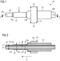
- the sheath 10 serving to produce a fully sealed access to the interior of a vessel of an animal or human body comprises a base sheath 20 having a tubular body defining a pass-through channel 22.
- a hemostatic valve 24 (cf. Fig. 6 ) terminates the sheath at the proximal end 20b.
- the pass-through channel 22 has an inner diameter d' and an outer diameter d.
- the inner diameter d' is dimensioned such that the sheath 10 is suitable to be pushed over a supply catheter 40 of a heart pump 70 (compare Figure 6 ) and preferably amounts to about 3 mm.
- the outer diameter d preferably amounts to about 3.33 mm to 5 mm, so that the sheath 10 is suitable for closing in a fully sealed manner a vessel aperture arising upon insertion of the introducer of the heart pump 70 through the vessel.
- the outer diameter d may need to be larger than 3.33 mm, based e.g. on the minimum wall thickness of the sheath 10, the size of a through channel 27 in a wall of the tubular body (cf. Fig. 2 ), or the size of the supply catheter 40 (cf. Fig. 6 ).
- the sheath 10 comprises an expansion device in the form of an expansion sheath 26 displaceable on the base sheath 20 in the direction R of the vessel aperture.
- the expansion sheath 26 is configured as an expansion sheath 26 tubularly encompassing the base sheath 20.
- the expansion sheath 26 is adapted to be displaced on the base sheath 20 in the direction R in order to increase the outer diameter d of the sheath in the region of the place of entry G into the vessel when the sheath 10 has been inserted into the vessel.
- An outer diameter D thereafter present in the region of the vessel aperture exceeds the original outer diameter d by the amount 2x, where 2x can be as large as 0.75 * d.
- the sheath 10 comprises a sleeve 28.
- the latter is preferably fastened at its distal end to the base sheath 20 and can furthermore be fastened at its proximal end to the fixation element 60.
- the sleeve 28 encases the base sheath 20 and the expansion sheath 26 such that the expansion sheath 26 is displaceable on the base sheath 20 between the base sheath 20 and the sleeve 28. In this way a traumatic effect of the expansion sheath 26 on the vessel can be prevented and sterility is maintained when the expansion sheath 26 is displaced along the base sheath 20 into the vessel aperture in order to increase the outer diameter of the sheath 10 in the vessel aperture.
- a wall 25 of the tubular body of the base sheath 20 has a through channel 27.
- the latter extends in the wall 25 from the proximal end 20b to the distal end 20a of the base sheath separately from the pass-through channel 22 of the base sheath 20 and preferably parallel to the pass-through channel 22.
- the through channel 27 is not separate from the pass-through channel 22 on its entire length, but e.g. only on the proximal end. On the distal end, the through channel 27 can form a sideways extension of the pass-through channel 22.
- the through channel 27 is adapted to conduct blood from the vessel (for example an artery) to the proximal end of the sheath 10 as soon as the sheath 10 has been inserted deep enough into the vessel. In this way a sufficient penetration depth into the vessel can be ascertained by means of the channel 27 in a simple manner.
- the sheath 10 can include an externally readable marked region in an area of the sheath, which, in operation, is intended to be located in the area of the vessel puncture site.
- External readability can e.g. be achieved by providing the region with radiopaque markers.
- fluorogenic or echogenic substances can be used for forming the markers.
- This region can, according to a first embodiment, which is shown in Fig. 2 and 3 , be defined by two limiting markers 29a and 29b. These markers further guide the expansion and help locate the correct position of the sheath in relation to the distal opening of through channel 27 and the vessel puncture site thereof.
- Respective markers can e.g. be provided on the sleeve 28 covering the base sheath 20 and on the base sheath 20.
- an expanding portion such as the above mentioned flexible portion and/or stretchable portion of the sheath, can be marked.
- Figure 3 shows another embodiment of a sheath 10 according to the invention.
- the expansion device 26' is configured as an inflation tube that is spirally wound around the base sheath 20. By inflating this tube, the outer diameter of the sheath is increased without affecting the bending flexibility of the device substantially.
- the embodiment according to Figure 4 shows a further type of expansion device 26.
- the base sheath 20 includes a flexible portion 26a between the proximal end 20b and the distal end 20a.
- the flexible portion 26a is configured to expand so as to increase the outer diameter of the sheath when the distal end portion of the base sheath 20 is pulled in the direction R of the proximal end by means of a pulling means 26b, 26c, 26d.
- a pulling means can e.g. include a slider 26d, which is located at the proximal end of the sheath.
- the slider 26d can be connected to a pull ring 26b, e.g. via a wire.
- This pull ring 26b is fixed to the base sheath 20 at the distal end, adjacent to the distal end of the flexible portion 26a.
- the flexible portion 26a of the sheath gradually expands in the desired manner so as to increase the outer diameter of the sheath 10.
- a ruler (not shown) can be provided e.g. on the base sheath 20 next to the slider 26d so that the degree of extension of the flexible portion 26a can easily be observed by the sliding distance or position of the slider 26d.
- the same result can basically be achieved by pushing the proximal end 20b towards the distal end 20a.
- the pulling means can be used in order to maintain the position of the proximal end of the sheath with respect to the vessel aperture.
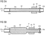
- the embodiment according to Figures 5a, 5b shows a further type of expansion device 26".
- the base sheath 20 includes a stretchable portion 26" between the proximal end 20b and the distal end 20a.
- the stretchable portion is configured to attain a first thickness in a stretched condition (cf. Fig. 5a ), and a second thickness, which is larger than the first thickness, in an unstretched condition (cf. Fig. 5b ).
- a pulling means as described with respect to Fig. 4 can be used in order to maintain the position of the proximal end of the sheath with respect to the vessel aperture, if necessary.
- FIG. 6 shows the sheath 10 of Figure 1 in a perspective view.
- the channel 27 can be connected via a suitable connection 32, 55 to different measuring devices, for example a blood pressure measuring device 30.
- a temperature measuring device for example a thermistor (not shown), can be connected to or inserted through the channel 27, for example in order to obtain information for the measurement of a patient's cardiac output.
- a guidewire 50 can further be inserted into the vessel.
- An access to the channel 27 can be created for example via a Luer connector 55.
- the sheath 10 is suited to be pushed over a supply catheter 40 of a heart pump 70.
- the heart pump 70, having the catheter 40, and the sheath 10 can be provided as a cohesive unit.
- the heart pump 70 is preferably introduced into the patient's vascular system here in the above-described manner by means of an introducing sheath which is removed using the peel-away technique and replaced by advancing the sheath 10.
- the above-mentioned fixation element 60 serves for fixing, for example stitching, the sheath 10 to the patient after insertion of the sheath into a vessel of the patient.
- openings 66 can be provided.
- the fixation element 60 possesses an area 62 spanning the base sheath 20 for applying a sterile cover (not shown).
- the area 62 of the fixation element 60 slopes down in a ramp shape on both sides of the base sheath 20 transversely to the principal direction of the base sheath.
- the fixation element 60 comprises a guide element 64 which serves as a stop for applying the sterile cover.
- the fixation element 60 may further comprise circulation openings 67 and/or circulation opening slots (not shown) in order to allow for air circulation under the sterile cover. These openings or slots pass through the fixation element preferably in the direction in which the sheath passes through.
Landscapes
- Health & Medical Sciences (AREA)
- Heart & Thoracic Surgery (AREA)
- Engineering & Computer Science (AREA)
- Life Sciences & Earth Sciences (AREA)
- Veterinary Medicine (AREA)
- Biomedical Technology (AREA)
- Animal Behavior & Ethology (AREA)
- General Health & Medical Sciences (AREA)
- Public Health (AREA)
- Anesthesiology (AREA)
- Hematology (AREA)
- Cardiology (AREA)
- Mechanical Engineering (AREA)
- Pulmonology (AREA)
- Vascular Medicine (AREA)
- Biophysics (AREA)
- Gastroenterology & Hepatology (AREA)
- Physiology (AREA)
- Physics & Mathematics (AREA)
- Pathology (AREA)
- Medical Informatics (AREA)
- Molecular Biology (AREA)
- Surgery (AREA)
- Media Introduction/Drainage Providing Device (AREA)
- Surgical Instruments (AREA)
Claims (16)
- Gaine (10) destinée à produire un accès percutané entièrement étanche à l'intérieur d'un vaisseau d'un corps d'animal ou d'être humain, comprenant :une gaine de base (20) présentant une extrémité distale (20a) et une extrémité proximale (20b), et un corps tubulaire définissant un canal de passage (22), la gaine de base (20) étant apte à être introduite dans le vaisseau à travers une ouverture de vaisseau de telle sorte qu'une région de la gaine (10) se trouve dans l'ouverture de vaisseau lorsque la gaine (10) se trouve dans une position fixe dans le vaisseau,caractérisée en ce que la gaine (10) comprend une valve hémostatique (24) à l'extrémité proximale (20b), etque la gaine (10) comprend en outre un dispositif d'expansion (26), lequel est apte à coopérer avec la gaine de base (20), de telle sorte que le diamètre extérieur (d; D) de la gaine (10) augmente dans la région de la gaine située dans l'ouverture de vaisseau, lorsque la gaine (10) se trouve dans la position fixe dans le vaisseau et suite à l'actionnement du dispositif d'expansion (26) pour fermer l'ouverture de vaisseau de manière entièrement étanche.
- Gaine (10) selon la revendication 1, dans laquelle le dispositif d'expansion (26) est configuré sous la forme d'une gaine à expansion (26) qui peut être déplacée sur la gaine de base (20) dans la direction (R) de l'ouverture de vaisseau.
- Gaine (10) selon la revendication 1, dans laquelle le dispositif d'expansion (26') est configuré sous la forme d'un tube de gonflage lequel est enroulé en spirale autour de la gaine de base (20).
- Gaine (10) selon la revendication 1, dans laquelle le dispositif d'expansion (26a, 26b, 26c, 26d) inclut une portion flexible (26a) de la gaine de base entre l'extrémité proximale (20b) et l'extrémité distale (20a), laquelle portion flexible est configurée pour l'expansion de manière à augmenter le diamètre extérieur de la gaine lorsque la portion d'extrémité distale de la gaine de base est tirée dans la direction de l'extrémité proximale à l'aide d'un moyen de traction (26b, 26c, 26d).
- Gaine (10) selon la revendication 1, dans laquelle le dispositif d'expansion (26") inclut une portion étirable (26") de la gaine de base entre l'extrémité proximale (20b) et l'extrémité distale (20a), laquelle portion étirable est configurée pour atteindre une première épaisseur dans une condition étirée, et une seconde épaisseur, laquelle est plus grande que la première épaisseur, dans une condition non étirée, de manière à augmenter le diamètre extérieur de la gaine lorsque la portion d'extrémité proximale de la gaine de base est libérée dans la direction de l'ouverture de vaisseau de la condition étirée à la condition non étirée.
- Gaine (10) selon l'une quelconque des revendications 1 à 5, comprenant un manchon (28), lequel enveloppe la gaine de base (20) et le dispositif d'expansion (26, 26', 26a), de telle sorte que le manchon (28) est en contact avec l'ouverture de vaisseau dans la position fixe de la gaine (10) dans le vaisseau.
- Gaine (10) selon la revendication 2, comprenant un manchon (28), lequel enveloppe la gaine de base (20) et le dispositif d'expansion (26), de telle sorte que le manchon (28) est en contact avec l'ouverture de vaisseau dans la position fixe de la gaine (10) dans le vaisseau, et que le dispositif d'expansion (26) peut être déplacé sur la gaine de base (20) entre la gaine de base (20) et le manchon (28).
- Gaine (10) selon l'une quelconque des revendications 1 à 7, dans laquelle le dispositif d'expansion (26) est apte à augmenter le diamètre extérieur (d) de la gaine (10) dans la région de l'ouverture de vaisseau à raison de 0,33 mm à 1,00 mm, de préférence à raison de 0,33 mm à 1,33 mm, et en particulier et de préférence à raison de 0,33 à 1,66 mm.
- Gaine (10) selon l'une quelconque des revendications 1 à 8, dans laquelle une paroi (25) du corps tubulaire de la gaine de base (20) présente un canal débouchant (27) s'étendant dans la paroi (25) de l'extrémité distale (20a) vers l'extrémité proximale (20b).
- Gaine (10) selon la revendication 9, dans laquelle le canal (27) est apte à acheminer du sang du vaisseau vers l'extrémité proximale (20b) de la gaine (10).
- Gaine (10) selon la revendication 10, comprenant un dispositif de mesure de la pression artérielle (30), lequel est raccordé au canal (27).
- Gaine (10) selon la revendication 10 ou 11, comprenant un élément de mesure de température introduit dans le canal (27).
- Gaine (10) selon l'une quelconque des revendications 9 à 12, comprenant un fil guide (50), lequel peut être introduit dans le vaisseau à partir de l'extrémité proximale (20b) de la gaine à travers le canal (27).
- Gaine (10) selon l'une quelconque des revendications 1 à 13, comprenant un élément de fixation (60) pour fixer la gaine (10) sur un patient, l'élément de fixation (60) présentant une zone (62) enjambant la gaine de base (20) pour appliquer une couverture stérile, la zone (62) s'affaissant suivant une forme de rampe sur les deux côtés de la gaine de base (20) transversalement à la direction principale de la gaine de base.
- Gaine (10) selon la revendication 14, dans laquelle l'élément de fixation (60) comprend une butée (64) pour appliquer la couverture stérile, ladite butée s'étendant sur l'extrémité proximale de la zone (62) transversalement à la direction principale de la gaine de base.
- Gaine (10) selon l'une quelconque des revendications 1 à 15, comprenant une pompe cardiaque (70) présentant un cathéter d'alimentation (40), la gaine (10) étant apte à être agencée d'une manière permettant le déplacement sur le cathéter d'alimentation (40).
Priority Applications (15)
| Application Number | Priority Date | Filing Date | Title |
|---|---|---|---|
| EP19170182.0A EP3650076A1 (fr) | 2014-07-04 | 2014-07-04 | Gaine pour l'accès étanche à un navire |
| ES14175797T ES2734216T3 (es) | 2014-07-04 | 2014-07-04 | Funda para acceso estanco a un vaso |
| EP14175797.1A EP2962721B1 (fr) | 2014-07-04 | 2014-07-04 | Gaine pour voie d'abord étanche par un vaisseau |
| DK14175797.1T DK2962721T3 (da) | 2014-07-04 | 2014-07-04 | Hylster til tætnet adgang til en åre |
| KR1020227038598A KR20220153680A (ko) | 2014-07-04 | 2015-07-06 | 혈관에의 밀폐된 접근을 위한 시스 |
| CN202010313711.XA CN111632263B (zh) | 2014-07-04 | 2015-07-06 | 用于密封到血管的通路的护套 |
| JP2017500015A JP6654619B2 (ja) | 2014-07-04 | 2015-07-06 | 血管への密閉されたアクセス用のシース |
| US15/323,660 US11730939B2 (en) | 2014-07-04 | 2015-07-06 | Sheath for sealed access to a vessel |
| PCT/EP2015/065290 WO2016001439A1 (fr) | 2014-07-04 | 2015-07-06 | Gaine pour un accès scellé de manière étanche à un vaisseau |
| CN201580036587.4A CN106659877B (zh) | 2014-07-04 | 2015-07-06 | 用于密封到血管的通路的护套 |
| KR1020177003160A KR102464849B1 (ko) | 2014-07-04 | 2015-07-06 | 혈관에의 밀폐된 접근을 위한 시스 |
| JP2019210072A JP6920400B2 (ja) | 2014-07-04 | 2019-11-21 | 血管への密閉されたアクセス用のシース |
| JP2021121210A JP7234306B2 (ja) | 2014-07-04 | 2021-07-26 | 血管への密閉されたアクセス用のシース |
| JP2023025864A JP2023054233A (ja) | 2014-07-04 | 2023-02-22 | 血管への密閉されたアクセス用のシース |
| US18/142,810 US20230381480A1 (en) | 2014-07-04 | 2023-05-03 | Sheath for sealed access to a vessel |
Applications Claiming Priority (1)
| Application Number | Priority Date | Filing Date | Title |
|---|---|---|---|
| EP14175797.1A EP2962721B1 (fr) | 2014-07-04 | 2014-07-04 | Gaine pour voie d'abord étanche par un vaisseau |
Related Child Applications (1)
| Application Number | Title | Priority Date | Filing Date |
|---|---|---|---|
| EP19170182.0A Division EP3650076A1 (fr) | 2014-07-04 | 2014-07-04 | Gaine pour l'accès étanche à un navire |
Publications (2)
| Publication Number | Publication Date |
|---|---|
| EP2962721A1 EP2962721A1 (fr) | 2016-01-06 |
| EP2962721B1 true EP2962721B1 (fr) | 2019-05-08 |
Family
ID=51136359
Family Applications (2)
| Application Number | Title | Priority Date | Filing Date |
|---|---|---|---|
| EP19170182.0A Pending EP3650076A1 (fr) | 2014-07-04 | 2014-07-04 | Gaine pour l'accès étanche à un navire |
| EP14175797.1A Active EP2962721B1 (fr) | 2014-07-04 | 2014-07-04 | Gaine pour voie d'abord étanche par un vaisseau |
Family Applications Before (1)
| Application Number | Title | Priority Date | Filing Date |
|---|---|---|---|
| EP19170182.0A Pending EP3650076A1 (fr) | 2014-07-04 | 2014-07-04 | Gaine pour l'accès étanche à un navire |
Country Status (8)
| Country | Link |
|---|---|
| US (2) | US11730939B2 (fr) |
| EP (2) | EP3650076A1 (fr) |
| JP (4) | JP6654619B2 (fr) |
| KR (2) | KR20220153680A (fr) |
| CN (2) | CN111632263B (fr) |
| DK (1) | DK2962721T3 (fr) |
| ES (1) | ES2734216T3 (fr) |
| WO (1) | WO2016001439A1 (fr) |
Families Citing this family (13)
| Publication number | Priority date | Publication date | Assignee | Title |
|---|---|---|---|---|
| DK2962720T3 (da) * | 2014-07-04 | 2020-03-16 | Abiomed Europe Gmbh | Hylster til forseglet adgang til et kar |
| KR20230095126A (ko) | 2017-03-21 | 2023-06-28 | 아비오메드, 인크. | 임베디드 서미스터를 갖는 카테터 장착 혈관 내 혈액 펌프로 심장을 연속적으로 지원하는동안 자연 심장 출력을 결정하는 시스템 및 방법 |
| EP3634528B1 (fr) | 2017-06-07 | 2023-06-07 | Shifamed Holdings, LLC | Dispositifs de déplacement de fluide intravasculaire, systèmes et procédés d'utilisation |
| US11197690B2 (en) * | 2017-09-14 | 2021-12-14 | Abiomed, Inc. | Integrated expandable access for medical device introducer |
| CN111556763B (zh) | 2017-11-13 | 2023-09-01 | 施菲姆德控股有限责任公司 | 血管内流体运动装置、系统 |
| DE102018201030A1 (de) | 2018-01-24 | 2019-07-25 | Kardion Gmbh | Magnetkuppelelement mit magnetischer Lagerungsfunktion |
| EP4085965A1 (fr) | 2018-02-01 | 2022-11-09 | Shifamed Holdings, LLC | Pompes à sang intravasculaires et procédés d'utilisation et de fabrication |
| DE102018211327A1 (de) | 2018-07-10 | 2020-01-16 | Kardion Gmbh | Laufrad für ein implantierbares, vaskuläres Unterstützungssystem |
| AU2020262078A1 (en) * | 2019-04-22 | 2021-12-23 | Abiomed, Inc. | Variable size repositioning sheath |
| US11964145B2 (en) | 2019-07-12 | 2024-04-23 | Shifamed Holdings, Llc | Intravascular blood pumps and methods of manufacture and use |
| US11654275B2 (en) | 2019-07-22 | 2023-05-23 | Shifamed Holdings, Llc | Intravascular blood pumps with struts and methods of use and manufacture |
| US11724089B2 (en) | 2019-09-25 | 2023-08-15 | Shifamed Holdings, Llc | Intravascular blood pump systems and methods of use and control thereof |
| DE102020102474A1 (de) | 2020-01-31 | 2021-08-05 | Kardion Gmbh | Pumpe zum Fördern eines Fluids und Verfahren zum Herstellen einer Pumpe |
Family Cites Families (74)
| Publication number | Priority date | Publication date | Assignee | Title |
|---|---|---|---|---|
| US4540411A (en) | 1983-11-28 | 1985-09-10 | Sherwood Medical Company | Catheter placement device |
| US4699611A (en) | 1985-04-19 | 1987-10-13 | C. R. Bard, Inc. | Biliary stent introducer |
| JPH02297381A (ja) | 1988-10-05 | 1990-12-07 | Abiomed Lp | 心機能助成気嚢及びその挿入方法 |
| US5234425A (en) | 1989-03-03 | 1993-08-10 | Thomas J. Fogarty | Variable diameter sheath method and apparatus for use in body passages |
| US5114401A (en) | 1990-02-23 | 1992-05-19 | New England Deaconess Hospital Corporation | Method for central venous catheterization |
| US5139486A (en) | 1991-01-02 | 1992-08-18 | Gerald Moss | Dilator/introducer for percutaneous gastrostomy |
| US5766151A (en) * | 1991-07-16 | 1998-06-16 | Heartport, Inc. | Endovascular system for arresting the heart |
| US5370685A (en) * | 1991-07-16 | 1994-12-06 | Stanford Surgical Technologies, Inc. | Endovascular aortic valve replacement |
| WO1993006878A1 (fr) | 1991-10-11 | 1993-04-15 | Boston Scientific Corporation | Manchon d'introduction destine a un catheter |
| US5282827A (en) | 1991-11-08 | 1994-02-01 | Kensey Nash Corporation | Hemostatic puncture closure system and method of use |
| US5395349A (en) | 1991-12-13 | 1995-03-07 | Endovascular Technologies, Inc. | Dual valve reinforced sheath and method |
| US5935122A (en) | 1991-12-13 | 1999-08-10 | Endovascular Technologies, Inc. | Dual valve, flexible expandable sheath and method |
| US5256150A (en) * | 1991-12-13 | 1993-10-26 | Endovascular Technologies, Inc. | Large-diameter expandable sheath and method |
| US5304142A (en) | 1992-08-04 | 1994-04-19 | Medamicus, Inc. | Dilator - Introducer locking hub and sheath valve apparatus |
| US5250038A (en) | 1992-10-09 | 1993-10-05 | Cook Incorporated | Multiple lumen vascular access introducer sheath |
| US5292309A (en) | 1993-01-22 | 1994-03-08 | Schneider (Usa) Inc. | Surgical depth measuring instrument and method |
| US6338730B1 (en) | 1993-02-04 | 2002-01-15 | Peter M. Bonutti | Method of using expandable cannula |
| US5320611A (en) | 1993-02-04 | 1994-06-14 | Peter M. Bonutti | Expandable cannula having longitudinal wire and method of use |
| US5360397A (en) | 1993-07-02 | 1994-11-01 | Corvita Corporation | Hemodiaylsis catheter and catheter assembly |
| US5492530A (en) | 1994-02-07 | 1996-02-20 | Cathco, Inc. | Method for accessing the coronary arteries from the radial or brachial artery in the arm |
| US5407430A (en) | 1994-03-21 | 1995-04-18 | Peters; Michael J. | Intravenous catheter |
| US5395341A (en) | 1994-03-21 | 1995-03-07 | Cordis Corporation | One piece vessel dilator/catheter sheath introducer |
| US5488960A (en) | 1994-04-11 | 1996-02-06 | Abbott Laboratories | Coronary sinus catheter introducer system |
| US5536255A (en) | 1994-10-03 | 1996-07-16 | Moss; Gerald | Dilator/introducer apparatus for percutaneous gastrostomy |
| US5971993A (en) | 1996-11-07 | 1999-10-26 | Myocardial Stents, Inc. | System for delivery of a trans myocardial device to a heart wall |
| US8323305B2 (en) * | 1997-02-11 | 2012-12-04 | Cardiva Medical, Inc. | Expansile device for use in blood vessels and tracts in the body and method |
| US5911702A (en) | 1997-11-06 | 1999-06-15 | Heartport, Inc. | Methods and devices for cannulating a patient's blood vessel |
| AR017498A1 (es) | 1998-03-13 | 2001-09-12 | Arteria Medical Science Llc | Dispositivo para proteccion contra embolizaciones, en angioplastia de carotida |
| SG76636A1 (en) * | 1998-12-22 | 2000-11-21 | Medinol Ltd | Apparatus and method for securing a stent on a balloon |
| EP1194074A4 (fr) * | 1999-05-19 | 2002-09-11 | Innerdyne Medical Inc | Systeme et procede d'etablissement d'acces vasculaire |
| US6692462B2 (en) | 1999-05-19 | 2004-02-17 | Mackenzie Andrew J. | System and method for establishing vascular access |
| US6607547B1 (en) | 1999-08-25 | 2003-08-19 | Origin Medsystems, Inc. | Longitudinal dilator and method |
| US20060287574A1 (en) | 1999-08-25 | 2006-12-21 | Chin Albert K | Longitudinal dilator |
| US7022100B1 (en) | 1999-09-03 | 2006-04-04 | A-Med Systems, Inc. | Guidable intravascular blood pump and related methods |
| ATE459388T1 (de) | 2001-12-26 | 2010-03-15 | Univ Yale | Gefäss-shuntvorrichtung |
| US7131963B1 (en) * | 2002-06-27 | 2006-11-07 | Advanced Cardiovascular Systems, Inc. | Catheters and methods of using catheters |
| US6999809B2 (en) | 2002-07-16 | 2006-02-14 | Edwards Lifesciences Corporation | Central venous catheter having a soft tip and fiber optics |
| US7488337B2 (en) * | 2002-09-30 | 2009-02-10 | Saab Mark A | Apparatus and methods for bone, tissue and duct dilatation |
| US6945957B2 (en) * | 2002-12-30 | 2005-09-20 | Scimed Life Systems, Inc. | Valve treatment catheter and methods |
| DE602004028382D1 (de) | 2003-10-03 | 2010-09-09 | Medtronic Inc | Erweiterbare führungsschleuse und gerät |
| US7194308B2 (en) * | 2003-11-12 | 2007-03-20 | Cardiac Pacemakers, Inc. | System and method for monitoring or reporting battery status of implantable medical device |
| US7993366B2 (en) * | 2004-05-27 | 2011-08-09 | Cardiva Medical, Inc. | Self-tensioning vascular occlusion device and method for its use |
| US7452351B2 (en) | 2004-04-16 | 2008-11-18 | Kyphon Sarl | Spinal diagnostic methods and apparatus |
| US20050234499A1 (en) * | 2004-04-19 | 2005-10-20 | Scimed Life Systems, Inc. | Multi-lumen balloon catheter including manifold |
| EP1819391B1 (fr) | 2004-09-09 | 2020-02-19 | Onset Medical Corporation | Gaine transluminale expansible |
| US20060084861A1 (en) | 2004-10-18 | 2006-04-20 | Topspin Medical (Isreal) Ltd. | Magnet and coil configurations for MRI probes |
| WO2006074044A2 (fr) | 2004-12-30 | 2006-07-13 | Neomend, Inc. | Procede et appareil pour fermeture de plaie par voie percutanee |
| US8556851B2 (en) * | 2005-07-05 | 2013-10-15 | Angioslide Ltd. | Balloon catheter |
| DE602006010171D1 (de) * | 2006-02-24 | 2009-12-17 | Nat Univ Ireland | Minimalinvasive intravaskuläre Behandlungsvorrichtung |
| WO2007119241A1 (fr) * | 2006-04-19 | 2007-10-25 | Transpid Ltd. | Appareil pour la régurgitation régulée de sang par l'intermédiaire d'une valvule tricuspide |
| US7906066B2 (en) * | 2006-06-30 | 2011-03-15 | Abbott Cardiovascular Systems, Inc. | Method of making a balloon catheter shaft having high strength and flexibility |
| US20090105545A1 (en) | 2007-10-17 | 2009-04-23 | Medical Research Products-B, Inc. | Apparatus and method for facilitating the implantation of a medical device |
| GB0712735D0 (en) | 2006-07-26 | 2007-08-08 | Smith & Nephew | Dressing |
| US20080051821A1 (en) | 2006-08-22 | 2008-02-28 | Gephart Matthew P | Tissue dilation tool and method of dilating tissue |
| US7905823B2 (en) * | 2006-08-30 | 2011-03-15 | Circulite, Inc. | Devices, methods and systems for establishing supplemental blood flow in the circulatory system |
| BRPI0717540A2 (pt) | 2006-09-28 | 2013-10-22 | Heart Leaflet Technologies Inc | Instrumento de fornecimento para o fornecimento percutâneo de uma prótese |
| US8795235B2 (en) * | 2006-10-06 | 2014-08-05 | Surgiquest, Inc. | Devices for and methods of performing minimally-invasive surgical procedures through a single incision |
| US7774072B2 (en) | 2006-11-30 | 2010-08-10 | Medtronic, Inc. | Attached implantable medical elongated members |
| EP2203139A4 (fr) * | 2007-10-12 | 2010-12-01 | Medical Res Products B Inc | Appareil médical et procédé destinés à faciliter la prise en charge de canaux tunnelisés à long terme |
| JP2011510796A (ja) * | 2008-02-05 | 2011-04-07 | シルク・ロード・メディカル・インコーポレイテッド | 介入カテーテルシステム及び方法 |
| US20090240202A1 (en) | 2008-03-21 | 2009-09-24 | William Joseph Drasler | Expandable introducer sheath |
| US8562559B2 (en) * | 2008-05-14 | 2013-10-22 | Onset Medical Corporation | Expandable iliac sheath and method of use |
| DE102008058864A1 (de) * | 2008-11-26 | 2010-05-27 | Aesculap Ag | Gefäßkanüle |
| US8460168B2 (en) | 2009-03-27 | 2013-06-11 | Circulite, Inc. | Transseptal cannula device, coaxial balloon delivery device, and methods of using the same |
| US10493246B2 (en) * | 2009-06-08 | 2019-12-03 | Trireme Medical, Inc. | Side branch balloon |
| US20170112480A9 (en) | 2010-12-17 | 2017-04-27 | Boston Scientific Scimed, Inc. | Expandable device sheath for vascular closure plug deployment |
| US8758402B2 (en) | 2010-12-17 | 2014-06-24 | Boston Scientific Scimed, Inc. | Tissue puncture closure device |
| EP2709712B1 (fr) * | 2011-05-16 | 2019-04-17 | Vivasure Medical Limited | Système de dilatation de gaine |
| JP2013013446A (ja) * | 2011-06-30 | 2013-01-24 | Terumo Corp | 医療器具固定具 |
| EP2606919A1 (fr) * | 2011-12-22 | 2013-06-26 | ECP Entwicklungsgesellschaft mbH | Dispositif de sas pour l'introduction d'un cathéter |
| US20130317438A1 (en) | 2012-05-25 | 2013-11-28 | Arstasis, Inc. | Vascular access configuration |
| US20130317481A1 (en) | 2012-05-25 | 2013-11-28 | Arstasis, Inc. | Vascular access configuration |
| US9179973B2 (en) * | 2013-03-15 | 2015-11-10 | St. Jude Medical, Cardiology Division, Inc. | Feedback systems and methods for renal denervation utilizing balloon catheter |
| KR102239216B1 (ko) | 2019-06-21 | 2021-04-13 | 재단법인 아산사회복지재단 | 의료용 유도관 |
-
2014
- 2014-07-04 DK DK14175797.1T patent/DK2962721T3/da active
- 2014-07-04 EP EP19170182.0A patent/EP3650076A1/fr active Pending
- 2014-07-04 ES ES14175797T patent/ES2734216T3/es active Active
- 2014-07-04 EP EP14175797.1A patent/EP2962721B1/fr active Active
-
2015
- 2015-07-06 CN CN202010313711.XA patent/CN111632263B/zh active Active
- 2015-07-06 WO PCT/EP2015/065290 patent/WO2016001439A1/fr active Application Filing
- 2015-07-06 CN CN201580036587.4A patent/CN106659877B/zh active Active
- 2015-07-06 US US15/323,660 patent/US11730939B2/en active Active
- 2015-07-06 KR KR1020227038598A patent/KR20220153680A/ko not_active Application Discontinuation
- 2015-07-06 JP JP2017500015A patent/JP6654619B2/ja active Active
- 2015-07-06 KR KR1020177003160A patent/KR102464849B1/ko active IP Right Grant
-
2019
- 2019-11-21 JP JP2019210072A patent/JP6920400B2/ja active Active
-
2021
- 2021-07-26 JP JP2021121210A patent/JP7234306B2/ja active Active
-
2023
- 2023-02-22 JP JP2023025864A patent/JP2023054233A/ja active Pending
- 2023-05-03 US US18/142,810 patent/US20230381480A1/en active Pending
Non-Patent Citations (1)
| Title |
|---|
| None * |
Also Published As
| Publication number | Publication date |
|---|---|
| JP2020036958A (ja) | 2020-03-12 |
| JP2021178194A (ja) | 2021-11-18 |
| JP2017524439A (ja) | 2017-08-31 |
| CN111632263A (zh) | 2020-09-08 |
| JP6920400B2 (ja) | 2021-08-18 |
| ES2734216T3 (es) | 2019-12-04 |
| KR20220153680A (ko) | 2022-11-18 |
| JP7234306B2 (ja) | 2023-03-07 |
| JP6654619B2 (ja) | 2020-02-26 |
| DK2962721T3 (da) | 2019-07-15 |
| WO2016001439A1 (fr) | 2016-01-07 |
| JP2023054233A (ja) | 2023-04-13 |
| EP2962721A1 (fr) | 2016-01-06 |
| CN106659877B (zh) | 2020-05-12 |
| KR102464849B1 (ko) | 2022-11-08 |
| US20170136225A1 (en) | 2017-05-18 |
| KR20170032342A (ko) | 2017-03-22 |
| CN111632263B (zh) | 2022-06-24 |
| US20230381480A1 (en) | 2023-11-30 |
| EP3650076A1 (fr) | 2020-05-13 |
| CN106659877A (zh) | 2017-05-10 |
| US11730939B2 (en) | 2023-08-22 |
Similar Documents
| Publication | Publication Date | Title |
|---|---|---|
| US20210146109A1 (en) | Sheath for sealed access to a vessel | |
| US20230381480A1 (en) | Sheath for sealed access to a vessel | |
| JP7084723B2 (ja) | 血管アクセスデバイス | |
| JP5602023B2 (ja) | 組織穿孔を探知及び封止するためのシステム及び方法 | |
| US10952710B2 (en) | Balloon closure device | |
| JP2020096855A (ja) | シースレス経橈骨動脈カテーテル法のための方法及び装置 | |
| EP2257322A1 (fr) | Procédé et appareil d accès vasculaire |
Legal Events
| Date | Code | Title | Description |
|---|---|---|---|
| PUAI | Public reference made under article 153(3) epc to a published international application that has entered the european phase |
Free format text: ORIGINAL CODE: 0009012 |
|
| AK | Designated contracting states |
Kind code of ref document: A1 Designated state(s): AL AT BE BG CH CY CZ DE DK EE ES FI FR GB GR HR HU IE IS IT LI LT LU LV MC MK MT NL NO PL PT RO RS SE SI SK SM TR |
|
| AX | Request for extension of the european patent |
Extension state: BA ME |
|
| 17P | Request for examination filed |
Effective date: 20160613 |
|
| RBV | Designated contracting states (corrected) |
Designated state(s): AL AT BE BG CH CY CZ DE DK EE ES FI FR GB GR HR HU IE IS IT LI LT LU LV MC MK MT NL NO PL PT RO RS SE SI SK SM TR |
|
| STAA | Information on the status of an ep patent application or granted ep patent |
Free format text: STATUS: EXAMINATION IS IN PROGRESS |
|
| 17Q | First examination report despatched |
Effective date: 20171019 |
|
| RIC1 | Information provided on ipc code assigned before grant |
Ipc: A61M 39/02 20060101AFI20180329BHEP Ipc: A61M 1/12 20060101ALI20180329BHEP Ipc: A61B 5/0215 20060101ALI20180329BHEP Ipc: A61M 39/06 20060101ALI20180329BHEP |
|
| GRAP | Despatch of communication of intention to grant a patent |
Free format text: ORIGINAL CODE: EPIDOSNIGR1 |
|
| STAA | Information on the status of an ep patent application or granted ep patent |
Free format text: STATUS: GRANT OF PATENT IS INTENDED |
|
| INTG | Intention to grant announced |
Effective date: 20180605 |
|
| GRAJ | Information related to disapproval of communication of intention to grant by the applicant or resumption of examination proceedings by the epo deleted |
Free format text: ORIGINAL CODE: EPIDOSDIGR1 |
|
| STAA | Information on the status of an ep patent application or granted ep patent |
Free format text: STATUS: EXAMINATION IS IN PROGRESS |
|
| INTC | Intention to grant announced (deleted) | ||
| GRAP | Despatch of communication of intention to grant a patent |
Free format text: ORIGINAL CODE: EPIDOSNIGR1 |
|
| STAA | Information on the status of an ep patent application or granted ep patent |
Free format text: STATUS: GRANT OF PATENT IS INTENDED |
|
| INTG | Intention to grant announced |
Effective date: 20181031 |
|
| GRAJ | Information related to disapproval of communication of intention to grant by the applicant or resumption of examination proceedings by the epo deleted |
Free format text: ORIGINAL CODE: EPIDOSDIGR1 |
|
| STAA | Information on the status of an ep patent application or granted ep patent |
Free format text: STATUS: EXAMINATION IS IN PROGRESS |
|
| GRAR | Information related to intention to grant a patent recorded |
Free format text: ORIGINAL CODE: EPIDOSNIGR71 |
|
| GRAS | Grant fee paid |
Free format text: ORIGINAL CODE: EPIDOSNIGR3 |
|
| STAA | Information on the status of an ep patent application or granted ep patent |
Free format text: STATUS: GRANT OF PATENT IS INTENDED |
|
| GRAA | (expected) grant |
Free format text: ORIGINAL CODE: 0009210 |
|
| STAA | Information on the status of an ep patent application or granted ep patent |
Free format text: STATUS: THE PATENT HAS BEEN GRANTED |
|
| INTC | Intention to grant announced (deleted) | ||
| INTG | Intention to grant announced |
Effective date: 20190328 |
|
| AK | Designated contracting states |
Kind code of ref document: B1 Designated state(s): AL AT BE BG CH CY CZ DE DK EE ES FI FR GB GR HR HU IE IS IT LI LT LU LV MC MK MT NL NO PL PT RO RS SE SI SK SM TR |
|
| REG | Reference to a national code |
Ref country code: GB Ref legal event code: FG4D |
|
| REG | Reference to a national code |
Ref country code: CH Ref legal event code: EP Ref country code: AT Ref legal event code: REF Ref document number: 1129237 Country of ref document: AT Kind code of ref document: T Effective date: 20190515 |
|
| REG | Reference to a national code |
Ref country code: IE Ref legal event code: FG4D |
|
| REG | Reference to a national code |
Ref country code: DE Ref legal event code: R096 Ref document number: 602014046153 Country of ref document: DE |
|
| REG | Reference to a national code |
Ref country code: NL Ref legal event code: FP |
|
| REG | Reference to a national code |
Ref country code: DK Ref legal event code: T3 Effective date: 20190711 |
|
| REG | Reference to a national code |
Ref country code: SE Ref legal event code: TRGR |
|
| REG | Reference to a national code |
Ref country code: CH Ref legal event code: NV Representative=s name: PATENTANWAELTE SCHAAD, BALASS, MENZL AND PARTN, CH |
|
| REG | Reference to a national code |
Ref country code: LT Ref legal event code: MG4D |
|
| PG25 | Lapsed in a contracting state [announced via postgrant information from national office to epo] |
Ref country code: AL Free format text: LAPSE BECAUSE OF FAILURE TO SUBMIT A TRANSLATION OF THE DESCRIPTION OR TO PAY THE FEE WITHIN THE PRESCRIBED TIME-LIMIT Effective date: 20190508 Ref country code: PT Free format text: LAPSE BECAUSE OF FAILURE TO SUBMIT A TRANSLATION OF THE DESCRIPTION OR TO PAY THE FEE WITHIN THE PRESCRIBED TIME-LIMIT Effective date: 20190908 Ref country code: FI Free format text: LAPSE BECAUSE OF FAILURE TO SUBMIT A TRANSLATION OF THE DESCRIPTION OR TO PAY THE FEE WITHIN THE PRESCRIBED TIME-LIMIT Effective date: 20190508 Ref country code: NO Free format text: LAPSE BECAUSE OF FAILURE TO SUBMIT A TRANSLATION OF THE DESCRIPTION OR TO PAY THE FEE WITHIN THE PRESCRIBED TIME-LIMIT Effective date: 20190808 Ref country code: HR Free format text: LAPSE BECAUSE OF FAILURE TO SUBMIT A TRANSLATION OF THE DESCRIPTION OR TO PAY THE FEE WITHIN THE PRESCRIBED TIME-LIMIT Effective date: 20190508 Ref country code: LT Free format text: LAPSE BECAUSE OF FAILURE TO SUBMIT A TRANSLATION OF THE DESCRIPTION OR TO PAY THE FEE WITHIN THE PRESCRIBED TIME-LIMIT Effective date: 20190508 |
|
| PG25 | Lapsed in a contracting state [announced via postgrant information from national office to epo] |
Ref country code: RS Free format text: LAPSE BECAUSE OF FAILURE TO SUBMIT A TRANSLATION OF THE DESCRIPTION OR TO PAY THE FEE WITHIN THE PRESCRIBED TIME-LIMIT Effective date: 20190508 Ref country code: BG Free format text: LAPSE BECAUSE OF FAILURE TO SUBMIT A TRANSLATION OF THE DESCRIPTION OR TO PAY THE FEE WITHIN THE PRESCRIBED TIME-LIMIT Effective date: 20190808 Ref country code: GR Free format text: LAPSE BECAUSE OF FAILURE TO SUBMIT A TRANSLATION OF THE DESCRIPTION OR TO PAY THE FEE WITHIN THE PRESCRIBED TIME-LIMIT Effective date: 20190809 Ref country code: LV Free format text: LAPSE BECAUSE OF FAILURE TO SUBMIT A TRANSLATION OF THE DESCRIPTION OR TO PAY THE FEE WITHIN THE PRESCRIBED TIME-LIMIT Effective date: 20190508 |
|
| REG | Reference to a national code |
Ref country code: ES Ref legal event code: FG2A Ref document number: 2734216 Country of ref document: ES Kind code of ref document: T3 Effective date: 20191204 |
|
| REG | Reference to a national code |
Ref country code: AT Ref legal event code: MK05 Ref document number: 1129237 Country of ref document: AT Kind code of ref document: T Effective date: 20190508 |
|
| PG25 | Lapsed in a contracting state [announced via postgrant information from national office to epo] |
Ref country code: CZ Free format text: LAPSE BECAUSE OF FAILURE TO SUBMIT A TRANSLATION OF THE DESCRIPTION OR TO PAY THE FEE WITHIN THE PRESCRIBED TIME-LIMIT Effective date: 20190508 Ref country code: AT Free format text: LAPSE BECAUSE OF FAILURE TO SUBMIT A TRANSLATION OF THE DESCRIPTION OR TO PAY THE FEE WITHIN THE PRESCRIBED TIME-LIMIT Effective date: 20190508 Ref country code: RO Free format text: LAPSE BECAUSE OF FAILURE TO SUBMIT A TRANSLATION OF THE DESCRIPTION OR TO PAY THE FEE WITHIN THE PRESCRIBED TIME-LIMIT Effective date: 20190508 Ref country code: EE Free format text: LAPSE BECAUSE OF FAILURE TO SUBMIT A TRANSLATION OF THE DESCRIPTION OR TO PAY THE FEE WITHIN THE PRESCRIBED TIME-LIMIT Effective date: 20190508 Ref country code: SK Free format text: LAPSE BECAUSE OF FAILURE TO SUBMIT A TRANSLATION OF THE DESCRIPTION OR TO PAY THE FEE WITHIN THE PRESCRIBED TIME-LIMIT Effective date: 20190508 |
|
| REG | Reference to a national code |
Ref country code: DE Ref legal event code: R097 Ref document number: 602014046153 Country of ref document: DE |
|
| PG25 | Lapsed in a contracting state [announced via postgrant information from national office to epo] |
Ref country code: MC Free format text: LAPSE BECAUSE OF FAILURE TO SUBMIT A TRANSLATION OF THE DESCRIPTION OR TO PAY THE FEE WITHIN THE PRESCRIBED TIME-LIMIT Effective date: 20190508 Ref country code: SM Free format text: LAPSE BECAUSE OF FAILURE TO SUBMIT A TRANSLATION OF THE DESCRIPTION OR TO PAY THE FEE WITHIN THE PRESCRIBED TIME-LIMIT Effective date: 20190508 |
|
| PLBE | No opposition filed within time limit |
Free format text: ORIGINAL CODE: 0009261 |
|
| STAA | Information on the status of an ep patent application or granted ep patent |
Free format text: STATUS: NO OPPOSITION FILED WITHIN TIME LIMIT |
|
| PG25 | Lapsed in a contracting state [announced via postgrant information from national office to epo] |
Ref country code: TR Free format text: LAPSE BECAUSE OF FAILURE TO SUBMIT A TRANSLATION OF THE DESCRIPTION OR TO PAY THE FEE WITHIN THE PRESCRIBED TIME-LIMIT Effective date: 20190508 |
|
| 26N | No opposition filed |
Effective date: 20200211 |
|
| REG | Reference to a national code |
Ref country code: BE Ref legal event code: MM Effective date: 20190731 |
|
| PG25 | Lapsed in a contracting state [announced via postgrant information from national office to epo] |
Ref country code: PL Free format text: LAPSE BECAUSE OF FAILURE TO SUBMIT A TRANSLATION OF THE DESCRIPTION OR TO PAY THE FEE WITHIN THE PRESCRIBED TIME-LIMIT Effective date: 20190508 |
|
| PG25 | Lapsed in a contracting state [announced via postgrant information from national office to epo] |
Ref country code: SI Free format text: LAPSE BECAUSE OF FAILURE TO SUBMIT A TRANSLATION OF THE DESCRIPTION OR TO PAY THE FEE WITHIN THE PRESCRIBED TIME-LIMIT Effective date: 20190508 Ref country code: LU Free format text: LAPSE BECAUSE OF NON-PAYMENT OF DUE FEES Effective date: 20190704 Ref country code: BE Free format text: LAPSE BECAUSE OF NON-PAYMENT OF DUE FEES Effective date: 20190731 |
|
| PG25 | Lapsed in a contracting state [announced via postgrant information from national office to epo] |
Ref country code: CY Free format text: LAPSE BECAUSE OF FAILURE TO SUBMIT A TRANSLATION OF THE DESCRIPTION OR TO PAY THE FEE WITHIN THE PRESCRIBED TIME-LIMIT Effective date: 20190508 |
|
| PG25 | Lapsed in a contracting state [announced via postgrant information from national office to epo] |
Ref country code: IS Free format text: LAPSE BECAUSE OF FAILURE TO SUBMIT A TRANSLATION OF THE DESCRIPTION OR TO PAY THE FEE WITHIN THE PRESCRIBED TIME-LIMIT Effective date: 20190908 |
|
| PG25 | Lapsed in a contracting state [announced via postgrant information from national office to epo] |
Ref country code: HU Free format text: LAPSE BECAUSE OF FAILURE TO SUBMIT A TRANSLATION OF THE DESCRIPTION OR TO PAY THE FEE WITHIN THE PRESCRIBED TIME-LIMIT; INVALID AB INITIO Effective date: 20140704 Ref country code: MT Free format text: LAPSE BECAUSE OF FAILURE TO SUBMIT A TRANSLATION OF THE DESCRIPTION OR TO PAY THE FEE WITHIN THE PRESCRIBED TIME-LIMIT Effective date: 20190508 |
|
| PG25 | Lapsed in a contracting state [announced via postgrant information from national office to epo] |
Ref country code: MK Free format text: LAPSE BECAUSE OF FAILURE TO SUBMIT A TRANSLATION OF THE DESCRIPTION OR TO PAY THE FEE WITHIN THE PRESCRIBED TIME-LIMIT Effective date: 20190508 |
|
| P01 | Opt-out of the competence of the unified patent court (upc) registered |
Effective date: 20230522 |
|
| PGFP | Annual fee paid to national office [announced via postgrant information from national office to epo] |
Ref country code: NL Payment date: 20230622 Year of fee payment: 10 Ref country code: IT Payment date: 20230620 Year of fee payment: 10 Ref country code: IE Payment date: 20230622 Year of fee payment: 10 Ref country code: FR Payment date: 20230621 Year of fee payment: 10 Ref country code: DK Payment date: 20230622 Year of fee payment: 10 |
|
| PGFP | Annual fee paid to national office [announced via postgrant information from national office to epo] |
Ref country code: SE Payment date: 20230622 Year of fee payment: 10 |
|
| PGFP | Annual fee paid to national office [announced via postgrant information from national office to epo] |
Ref country code: GB Payment date: 20230620 Year of fee payment: 10 Ref country code: ES Payment date: 20230801 Year of fee payment: 10 Ref country code: CH Payment date: 20230801 Year of fee payment: 10 |
|
| PGFP | Annual fee paid to national office [announced via postgrant information from national office to epo] |
Ref country code: DE Payment date: 20230620 Year of fee payment: 10 |