EP2962587A1 - Sports shoe - Google Patents
Sports shoe Download PDFInfo
- Publication number
- EP2962587A1 EP2962587A1 EP15001876.0A EP15001876A EP2962587A1 EP 2962587 A1 EP2962587 A1 EP 2962587A1 EP 15001876 A EP15001876 A EP 15001876A EP 2962587 A1 EP2962587 A1 EP 2962587A1
- Authority
- EP
- European Patent Office
- Prior art keywords
- shoe
- guide element
- base
- intermediate guide
- longitudinal bar
- Prior art date
- Legal status (The legal status is an assumption and is not a legal conclusion. Google has not performed a legal analysis and makes no representation as to the accuracy of the status listed.)
- Withdrawn
Links
Images


Classifications
-
- A—HUMAN NECESSITIES
- A43—FOOTWEAR
- A43B—CHARACTERISTIC FEATURES OF FOOTWEAR; PARTS OF FOOTWEAR
- A43B5/00—Footwear for sporting purposes
- A43B5/04—Ski or like boots
- A43B5/0411—Ski or like boots for cross-country
- A43B5/0413—Adaptations for soles or accessories associated with soles for cross-country bindings
-
- A—HUMAN NECESSITIES
- A43—FOOTWEAR
- A43B—CHARACTERISTIC FEATURES OF FOOTWEAR; PARTS OF FOOTWEAR
- A43B5/00—Footwear for sporting purposes
- A43B5/04—Ski or like boots
- A43B5/0427—Ski or like boots characterised by type or construction details
- A43B5/047—Ski or like boots characterised by type or construction details provided with means to improve walking with the skiboot
-
- A—HUMAN NECESSITIES
- A43—FOOTWEAR
- A43B—CHARACTERISTIC FEATURES OF FOOTWEAR; PARTS OF FOOTWEAR
- A43B5/00—Footwear for sporting purposes
- A43B5/04—Ski or like boots
- A43B5/0492—Telemark boots
- A43B5/0494—Adaptations for soles or accessories associated with soles for telemark bindings
-
- A—HUMAN NECESSITIES
- A43—FOOTWEAR
- A43B—CHARACTERISTIC FEATURES OF FOOTWEAR; PARTS OF FOOTWEAR
- A43B5/00—Footwear for sporting purposes
- A43B5/04—Ski or like boots
- A43B5/0496—Ski or like boots boots for touring or hiking skis
Definitions
- the invention relates to a shoe designed to be held reversibly to a sports gliding device, and more particularly to a shoe intended for the practice of a snow sport.
- Such shoes can be used in areas such as cross-country skiing, ski touring, telemark, snowshoeing, or other.
- a shoe of this family generally comprises an outer sole, a rod and an attachment element, the latter being provided to cooperate with a locking mechanism itself intended to be subject to the machine.
- the hooking element and the locking mechanism are a hooking means which, very often, is provided to hold the boot on the machine in a reversible manner.
- each locking mechanism In the field of cross-country skiing, it is usual for each locking mechanism to either hold a shoe or release it. This allows the choice to drive the skis or walk.
- the foot can unfold, or flex relative to the lower leg, which allows the guidance of the ski when in contact with the ground, for example in a sliding phase or in a support phase, or controlling the position of the ski when it is away from the ground, for example in a return phase of the ski forward after a thrust with back support.
- the observed phenomena are variable according to the users, because they have different weights, different sizes, different levels of practice, different driving styles.
- the conditions of use may vary depending on factors such as snow quality, inclination of the ground, or other. It generally appears that a shoe of given structure is not necessarily adapted to any user, or that if it is in some cases it is not in all cases. This is to say that a shoe is generally not versatile enough in the sense that it does not satisfy a user in all possible conditions of use.
- the invention generally seeks to improve a shoe. More specifically, the invention seeks to improve the transmission of driving pulses, the return of the reactions of the ground or of a machine, or the perception of sensory information. More specifically, the invention seeks to optimize the driving efficiency and reduce the fatigue of a user.
- the invention also wishes to make the shoe more versatile, that is to say, to make it suitable for the largest number of users. In particular, any user should obtain maximum efficiency in the transmission of driving impulses or in the perception of sensory information related to driving, regardless of the conditions of use.
- the invention proposes a shoe designed to be held reversibly to a sports machine, the shoe comprising a base, which extends in length from a rear end to a front end, in width between a lateral edge and a medial edge, and in height between a face of cooperation with the machine and an inner face, the base having, from the rear end to the front end, a rear zone, a central zone, a metatarsal zone, and a front zone, the shoe comprising a front guide element, located in the front zone on the side of the cooperation face.
- the shoe according to the invention is characterized in that it comprises an intermediate guide element, which is situated at least partly in the metatarsal zone on the side of the cooperation face, and in that it comprises a means for removably connecting the intermediate guide member with respect to the base.
- the structure of the shoe according to the invention allows the introduction or removal of the intermediate guide element.
- a change in the intermediate guide element in some cases can change the mechanical characteristics of the shoe, at the base. For example, changing the stiffness of the element changes the longitudinal flexural characteristics of the shoe at the base.
- the invention allows the optimization of mechanical properties of the shoe, such as the bending ability at the base along a transverse axis.
- the user can walk or drive a machine by performing natural movements, such as unwinding or flexing the foot, with particularly limited discomfort, or even without embarrassment.
- the invention improves the transmission of driving pulses, the return of the reactions of the ground or of a machine, or the perception of sensory information.
- the driving performance is better than with a shoe according to the prior art.
- the user is less tired, and his performance is better.
- the shoe according to the invention is more versatile because it can be better adapted to the specificities or needs of a user.
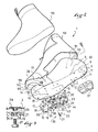
- Figures 1 to 8 it is with the help of Figures 1 to 8 that is presented the first form.
- a shoe 1 designed to accommodate the foot of the user. It will be seen later that the shoe can be held reversibly to a sports machine, for example a ski, which is not shown here.
- the shoe 1 comprises a base 2, which extends in length from a rear end 3 to a front end 4, in width between a lateral edge 5 and a medial edge 6, and in height between a face 7 with the machine and an inner face 8.
- the cooperation face 7 can, in unrepresented configurations, come into contact with the machine directly or indirectly.
- an intermediate element such as a retaining device and / or an interface plate, is placed between the boot and the machine.
- the inner face 8, as for it and as will be better understood later, can come into contact with the foot of the user directly or indirectly.
- the base 2 has, from the rear end 3 to the front end 4, a rear zone 11, provided to come opposite the heel of the foot, a central zone 12 , which comes next to the arch, a metatarsal area 13, which is next to the metatarsal, and a front zone 14, which comes next to the toes.
- the shoe also comprises a front guide element 15, located in the front zone 14 on the side of the cooperation face 7.
- the front guide member 15 here comprises a first longitudinal bar 16 and a second longitudinal bar 17, and a bridge 18 which connects to one another the first longitudinal bar and the second longitudinal bar. It will be seen better after the front guide member 15 is connected to the base 2 removably, for example by means of one or more screw-nut devices.
- the shoe 1 comprises an intermediate guide element 21, which is located at least partly in the metatarsal area 13 on the side of the cooperation face 7, and the shoe comprises a removable connecting means 22 of the intermediate guide element with respect to the base 2.
- the intermediate guide element 21 can be placed on the base, or removed. It is therefore possible to replace this element with another. Replacement can take place in case of wear, or to change the mechanical characteristics. This means that a change of the intermediate guide element in some cases can change the mechanical characteristics of the shoe, at the base 2. For example, by changing the stiffness of the element 21, the stiffness is changed at the base level.
- the user has several guide elements, he can select the one that suits him for a given use. It thus optimizes the mechanical properties of the shoe, as the ability to flex the base along a transverse axis. As a result he can walk or drive a craft by performing natural movements, such as unwinding or flexing the foot, with a particularly reduced discomfort, or even without embarrassment. The driving performance is improved.
- the intermediate guide element 21 comprises a first longitudinal bar 23 and a second longitudinal bar 24, as well as a bridge 25 which connects the first longitudinal bar 23 and the second longitudinal bar 24 to each other.
- 23, 24 and the bridge 25 form a single piece, made for example using a synthetic material. Polyurethane, polyethylene, or any other equivalent material may be suitable.
- the space 26 between the bars 23, 24 delimits a longitudinal guiding groove, designed to cooperate with a protrusion disposed optionally on the ski or on the intermediate element between the ski and the boot.
- the guide groove 26 guides the base 2 in the direction of the length of the shoe.
- the intermediate guide member comprises two or more longitudinal bars, excluding any bridge. Each bar is then secured as it is at the base.
- Each longitudinal bar 23, 24 of the intermediate guide member 21 has notches 26, only one is designated in each figure concerned for the sake of clarity.
- the cuts can be of different shapes.
- the notches open transversely and opposite the base 2.
- the bridge 25 takes up against the base 2, or near the base 2. This provision promotes a longitudinal flexion, that is to say by relative to a transverse axis parallel to the base, the intermediate guide element 21.
- the notches 26 are here aligned in two transversely: a notch of a bar 23 is opposite a notch of the other bar 24, for an optimization of the bending ability previously mentioned.
- the detachable connection means 22 of the intermediate guide element 21 relative to the base 2 comprises at least one screw-nut device. Only one of these is detailed, to show that it comprises a screw 27 and a nut 28.
- the screw 27 is placed on the side of the cooperation face 7 by passing through the intermediate guide element 21 and the base 2, while the nut 28 takes place on the side of the inner face 8 of the base.
- the intermediate guide element 21 has an orifice 29, and the base 2 has an orifice 30.
- the removable connecting means 22 comprises six screw-nut devices.
- the shoe 1 comprises a removable connection means 32 of the front guide member 15 with respect to the base 2.
- the removable connection means 32 of the front guide element It also includes at least one screw-and-nut device. And again it is for example used a screw 27 and a nut 28, set up as seen above.
- the detachable connection means 22 and the detachable connection means 32 have common elements, namely two screws 27 and two nuts 28.
- the screws and nuts in question simultaneously hold the intermediate guide element 21 and the front guide member 15.
- Each element 21, 15 may be more or less rigid, to adjust the ability of the shoe 1 to flex longitudinally, particularly at the base 2. This allows for example to adapt the shoe to the level of practice of a user .
- the boot 1 comprises, if desired, a wedge 33 disposed between the intermediate guide element 21 and the base 2.
- the wedge 33 is constituted by a plate, made for example of synthetic material, such as polyurethane, polyethylene, a layer of resin or thermoplastic material reinforced with fibers or any other charge, or the like.
- the shim 33 is retained between the intermediate guide element 21 and the base 2, by the action of the removable connection means 22, that is to say here by the action of screw-nut devices.
- the wedge 33 has orifices 34 for the passage of the screws 27.
- the shim 33 extends only facing the intermediate guide element 21. This makes it possible to adjust the rigidity of the boot, with regard to its longitudinal flexion at the base 2, in the metatarsal zone 13.
- the shim 33 extends opposite the intermediate guide element 21 and facing the element of It then follows that the adjustment of the rigidity of the shoe is done in the metatarsal zone 13 and in the front zone 14.
- first longitudinal bar 16 of the front guide member 15 is aligned with the first longitudinal bar 23 of the intermediate guide member 21, and that the second longitudinal bar 17 of the front guide member 15 is aligned with the second longitudinal bar 24 of the intermediate guide element 21.
- This allows a longitudinal guide of the base 2 at both the front zone 14 and the metatarsal zone 13.
- the boot 1 comprises means for positioning the intermediate guide element 21 with respect to the front guide element 15. This is to guarantee the relative alignment of the guide elements 21, 15.
- the positioning means by the action of the positioning means, the first bar 16 of the front element 15 is aligned with the first bar 23 of the intermediate element 21, and the second bar 17 of the front element 15 is aligned with the second bar 24 of the intermediate element 21.
- the positioning means of the intermediate guide element 21 with respect to the front guide element 15 has a stop 35 on the intermediate guide element 21 and a stop 36 on the intermediate guide element 21.
- the stops 35, 36 are shaped to bear against each other.
- the stop 35 of the intermediate guide element 21 is fragmented, and the stop 36 of the front guide element 15 is fragmented.
- the stop 35 comprises a tongue 41 at the first longitudinal bar 23, and a tongue 42 at the second longitudinal bar 24.
- the stop 36 comprises a tongue 43 at the level of the first longitudinal bar 16, and a tongue 44 at the second longitudinal bar 17. It is observed that the tabs 41, 43 of the first bars 23, 16 and the tabs 42, 44 of the second bars 24, 17 are superimposed. In fact, each tongue 41, 42, 42, 44 is a thinned end of a bar. This makes it easy to apply one to the contact of the other.
- the structure of the shoe 1 is such that in the rear zone 11 and in the central zone 12 the base 2 is extended, on the side of the inner face 8, by a lateral wall 51, a rear wall 52 and a medial wall 53, to form a rear footwear, and such that, in the front zone 14, the base 2 is extended, on the side of the inner face 8, by a side wall 54, a front wall 55 and a medial wall 56, for forming a front footwear volume, a transverse slot 57 remaining between the rear and front footwear, and still such that a flexible cover 58 covers the front footwear volume, the transverse slot 57, and the rear footwear volume.
- the shoe 1 comprises a shoe 59, which can be made by any technique known to a person skilled in the art.
- the slipper 59 takes place against the inner face 8 of the base 2, being covered by the flexible cover 58.
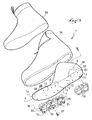
- FIG. 9 there is a shoe 1, with a base 2, a rear end 3, a front end 4, a lateral edge 5, a medial edge 6, a cooperation face 7 and an inner face 8.
- a rear zone 11 There is also a rear zone 11 , a central zone 12, a metatarsal zone 13 and a front zone 14, as well as a front guide element 15 and an intermediate guide element 21.
- the base 2 is extended, on the side of the inner face 8, by a side wall 61, a rear wall 62 and a medial wall 63, to form a rear footwear volume, the base 2 having the appearance of a blade forward 4, and it is also that the shoe 1 comprises a flexible rod 64 affixed to the base being nested in the rear footwear volume.
- a liner 59 is inserted into the rod 64.
- the liner may be removable, that is to say, able to be removed from the rod.
- the shoe can alternatively be secured permanently to the stem by any appropriate technique, such as a collage, or other.
- the intermediate guide element 21 and the front guide element 15 form a single piece, which is removable, that is to say, separable from the base 2.
- the intermediate guide element 21 and the front guide element 15 form a single piece, which is removable, that is to say, separable from the base 2.
- the shoe 1 comprises a detachable connecting means of the one-piece piece relative to the base 2.
- the intermediate guide member 21 comprises a first longitudinal bar 86, a second longitudinal bar 87 and a third longitudinal bar 88, as well as a bridge 89 which connects together the first longitudinal bar 86, the second longitudinal bar 87, and the third longitudinal bar 88.
- This structure allows the boot 1 to be guided longitudinally, via the intermediate guide element 21, by two projections disposed at will on the ski or on the intermediate element between the ski and the shoe.
- the guide elements 15, 21 have been shown associated with a base 2, it can alternatively be provided that these elements are associated with a sole assembly consisting of one or more layers, the sole assembly being secured to a rod for to form a shoe.
- the shoe 1 comprises a rear guide element 91, which is, optionally, removable or non-removable.
- the boot 1 comprises a hooking means provided to cooperate with a ski retainer.
- the attachment means here comprises, by way of non-limiting example, a first attachment element 92 and a second attachment element 93, knowing that only one can be provided.
- Each element 92, 93 has a subdivision of circular section. It is observed that at least one fastening element 92, 93 is secured to the front guide element 15. The fastening element extends between the bars 16, 17, and is set back from a surface the guide member 15 provided to bear on the ground. In other words, at least one subdivision of one or both fastening elements is closer to the base 2 than are the ends of the studs materialized by the notches 26.
Abstract
Chaussure (1) prévue pour être retenue de manière réversible à un engin de sport , la chaussure (1) comprenant une base (2), lacluelle s'étend en longueur depuis une extrémité arrière (3) jusqu'à une extrémité avant (4), en largeur entre un bord latéral (5) et un bord médial (6), et en hauteur entre une face de coopération (7) avec l'engin et une face interne (8), la base (2) présentant, depuis l'extrémité arrière (3) jusqu'à l'extrémité avant (4), une zone arrière (11), une zone centrale (12), une zone de métatarse (13), et une zone avant (14), la chaussure (1) comprenant un élément de guidage avant (15), situé dans la zone avant (14) du côté de la face de coopération (7), La chaussure (1) comprend un élément de guidage intermédiaire (21), lequel est situé en partie au moins dans la zone de métatarse (13) du côté de la face de coopération (7). La chaussure (1) comprend un moyen de liaison amovible (22) de l'élément de guidage intermédiaire (21) par rapport à la base (2).Shoe (1) designed to be reversibly retained on a sports apparatus, the shoe (1) comprising a base (2), the flange extends in length from a rear end (3) to a front end (4). ), in width between a lateral edge (5) and a medial edge (6), and in height between a cooperation face (7) with the machine and an inner face (8), the base (2) having, since the rear end (3) to the front end (4), a rear area (11), a central area (12), a metatarsal area (13), and a front area (14), the shoe (1) comprising a front guide element (15), located in the front zone (14) on the side of the cooperation face (7), The shoe (1) comprises an intermediate guide element (21), which is located at least partly in the metatarsal area (13) on the side of the cooperation face (7). The shoe (1) comprises a removable connection means (22) of the intermediate guide element (21) relative to the base (2).
Description
L'invention se rapporte à une chaussure prévue pour être retenue de manière réversible à un engin de sport de glisse, et concerne plus particulièrement une chaussure destinée à la pratique d'un sport de neige.The invention relates to a shoe designed to be held reversibly to a sports gliding device, and more particularly to a shoe intended for the practice of a snow sport.
De telles chaussures peuvent être utilisées dans des domaines tels que le ski de fond, la randonnée à ski, le télémark, la raquette à neige, ou autre.Such shoes can be used in areas such as cross-country skiing, ski touring, telemark, snowshoeing, or other.
Une chaussure de cette famille comprend généralement un semelage externe, une tige et un élément d'accrochage, ce dernier étant prévu pour coopérer avec un mécanisme de verrouillage lui-même prévu pour être assujetti à l'engin. L'élément d'accrochage et le mécanisme de verrouillage constituent un moyen d'accrochage qui, très souvent, est prévu pour retenir la chaussure sur l'engin de manière réversible.A shoe of this family generally comprises an outer sole, a rod and an attachment element, the latter being provided to cooperate with a locking mechanism itself intended to be subject to the machine. The hooking element and the locking mechanism are a hooking means which, very often, is provided to hold the boot on the machine in a reversible manner.
Par exemple, dans le domaine du ski de fond, il est habituel que chaque mécanisme de verrouillage puisse soit retenir une chaussure, soit la libérer. Cela permet au choix de conduire les skis ou de marcher.For example, in the field of cross-country skiing, it is usual for each locking mechanism to either hold a shoe or release it. This allows the choice to drive the skis or walk.
Il est également habituel de permettre à l'arrière de la chaussure, c'est-à-dire au talon, d'alternativement s'éloigner puis se rapprocher du ski selon des cycles répétés. Cela facilite la conduite, notamment parce qu'un utilisateur peut effectuer des mouvements plus libres qu'il ne le pourrait avec les talons immobilisés. Le corollaire de cette liberté des mouvements du talon est que, pour chaque pied, ce sont principalement les orteils et la région du métatarse qui conditionnent la conduite du ski. Cela signifie que, par exemple, la transmission d'impulsions de conduite, la restitution des réactions du sol, la perception d'informations sensorielles, ou autre, se font pour beaucoup vers l'avant du pied. Cet agencement habituel notamment dans le domaine du ski de fond est satisfaisant, entre autres, parce qu'il permet une conduite par des mouvements naturels ou quasi naturels. En effet, le pied peut se dérouler, ou fléchir par rapport au bas de jambe, ce qui permet le guidage du ski lorsqu'il est au contact du sol, par exemple dans une phase de glisse ou dans une phase d'appui, ou le contrôle de la position du ski lorsqu'il est à l'écart du sol, par exemple dans une phase de retour du ski vers l'avant après une poussée avec appui arrière.It is also usual to allow the back of the shoe, that is to say the heel, to alternately move away and then approach the ski in repeated cycles. This makes driving easier, especially because a user can move more freely than he could with the stubborn heels. The corollary of this freedom of movement of the heel is that for each foot, it is mainly the toes and the metatarsal region that condition the conduct of the ski. This means that, for example, the transmission of driving impulses, the restitution of the reactions of the ground, the perception of sensory information, or other, are done for many towards the front of the foot. This usual arrangement especially in the field of cross-country skiing is satisfactory, inter alia, because it allows driving by natural or quasi-natural movements. Indeed, the foot can unfold, or flex relative to the lower leg, which allows the guidance of the ski when in contact with the ground, for example in a sliding phase or in a support phase, or controlling the position of the ski when it is away from the ground, for example in a return phase of the ski forward after a thrust with back support.
Cependant, quelques inconvénients liés à cet agencement ont pu être observés.However, some disadvantages related to this arrangement could be observed.
Tout d'abord, pour certains utilisateurs, il a été remarqué que la transmission d'impulsions de conduite, la restitution des réactions au sol, ou de manière plus large la perception d'informations sensorielles, sont parfois un peu difficiles ou un peu incomplètes. En d'autres termes le rendement de conduite n'est pas toujours satisfaisant. Il en résulte des fatigues supplémentaires et des baisses de performances, surtout lors d'utilisations sportives.First of all, for some users, it has been noticed that the transmission of driving impulses, the restitution of the reactions on the ground, or in a wider way the perception of sensory information, are sometimes a little difficult or a little incomplete. . In other words the driving performance is not always satisfactory. This results in additional fatigue and performance declines, especially during sports uses.
Pour chaque type de chaussure les phénomènes observés sont variables selon les utilisateurs, car ceux-ci ont des poids différents, des tailles différentes, des niveaux de pratique différents, des styles de conduite différents. De plus les conditions d'utilisation peuvent varier en fonction de facteurs comme la qualité de la neige, l'inclinaison du sol, ou autre. Il apparaît d'une manière générale qu'une chaussure de structure donnée n'est pas forcément adaptée à tout utilisateur, ou que si elle l'est dans certains cas elle ne l'est pas dans tous les cas. Cela revient à dire qu'une chaussure n'est généralement pas suffisamment polyvalente, dans le sens où elle ne satisfait pas un utilisateur dans toutes les conditions d'utilisation possibles.For each type of shoe the observed phenomena are variable according to the users, because they have different weights, different sizes, different levels of practice, different driving styles. In addition, the conditions of use may vary depending on factors such as snow quality, inclination of the ground, or other. It generally appears that a shoe of given structure is not necessarily adapted to any user, or that if it is in some cases it is not in all cases. This is to say that a shoe is generally not versatile enough in the sense that it does not satisfy a user in all possible conditions of use.
Par rapport à cela l'invention cherche globalement à améliorer une chaussure. Plus précisément l'invention veut améliorer la transmission d'impulsions de conduite, la restitution des réactions du sol ou d'un engin, ou la perception d'informations sensorielles. Plus précisément encore l'invention veut optimiser le rendement de conduite, et réduire la fatigue d'un utilisateur. L'invention souhaite aussi rendre la chaussure plus polyvalente, c'est-à-dire faire en sorte de l'adapter au plus grand nombre d'utilisateurs. Notamment, il faudrait que tout utilisateur obtienne un rendement maximal dans la transmission des impulsions de conduite ou dans la perception des informations sensorielles liées à la conduite, et ce quelles que soient les conditions d'utilisation.In relation to this, the invention generally seeks to improve a shoe. More specifically, the invention seeks to improve the transmission of driving pulses, the return of the reactions of the ground or of a machine, or the perception of sensory information. More specifically, the invention seeks to optimize the driving efficiency and reduce the fatigue of a user. The invention also wishes to make the shoe more versatile, that is to say, to make it suitable for the largest number of users. In particular, any user should obtain maximum efficiency in the transmission of driving impulses or in the perception of sensory information related to driving, regardless of the conditions of use.
Pour ce faire, l'invention propose une chaussure prévue pour être retenue de manière réversible à un engin de sport , la chaussure comprenant une base, laquelle s'étend en longueur depuis une extrémité arrière jusqu'à une extrémité avant, en largeur entre un bord latéral et un bord médial, et en hauteur entre une face de coopération avec l'engin et une face interne, la base présentant, depuis l'extrémité arrière jusqu'à l'extrémité avant, une zone arrière, une zone centrale, une zone de métatarse, et une zone avant, la chaussure comprenant un élément de guidage avant, situé dans la zone avant du côté de la face de coopération.To do this, the invention proposes a shoe designed to be held reversibly to a sports machine, the shoe comprising a base, which extends in length from a rear end to a front end, in width between a lateral edge and a medial edge, and in height between a face of cooperation with the machine and an inner face, the base having, from the rear end to the front end, a rear zone, a central zone, a metatarsal zone, and a front zone, the shoe comprising a front guide element, located in the front zone on the side of the cooperation face.
La chaussure selon l'invention est caractérisée par le fait qu'elle comprend un élément de guidage intermédiaire, lequel est situé en partie au moins dans la zone de métatarse du côté de la face de coopération, et par le fait qu'elle comprend un moyen de liaison amovible de l'élément de guidage intermédiaire par rapport à la base.The shoe according to the invention is characterized in that it comprises an intermediate guide element, which is situated at least partly in the metatarsal zone on the side of the cooperation face, and in that it comprises a means for removably connecting the intermediate guide member with respect to the base.
La structure de la chaussure selon l'invention permet la mise en place ou le retrait de l'élément de guidage intermédiaire. De plus, il est possible de remplacer un élément de guidage intermédiaire par un autre. Cela signifie par exemple qu'il est possible de remplacer un élément de guidage usé par un autre, neuf ou moins usé. Il s'agit là d'une logique de maintenance. Il est également possible de remplacer un élément de guidage qui présente des caractéristiques mécaniques données, par un autre élément de guidage aux caractéristiques mécaniques différentes. En d'autres termes, un changement de l'élément de guidage intermédiaire permet dans certains cas de modifier des caractéristiques mécaniques de la chaussure, au niveau de la base. Par exemple, en changeant la raideur de l'élément, on change les caractéristiques de flexion longitudinale de la chaussure au niveau de la base.The structure of the shoe according to the invention allows the introduction or removal of the intermediate guide element. In addition, it is possible to replace one intermediate guide element with another. This means for example that it is possible to replace a worn guiding element with another, new or less worn. This is a maintenance logic. It is also possible to replace a guide element which has given mechanical characteristics, by another guide element with different mechanical characteristics. In other words, a change in the intermediate guide element in some cases can change the mechanical characteristics of the shoe, at the base. For example, changing the stiffness of the element changes the longitudinal flexural characteristics of the shoe at the base.
Si l'utilisateur dispose de plusieurs éléments de guidage, il peut sélectionner celui qui lui convient le mieux pour une utilisation donnée. En d'autres termes, l'invention permet l'optimisation de propriétés mécaniques de la chaussure, comme l'aptitude à la flexion au niveau de la base selon un axe transversal.If the user has several guiding elements, he can select the one that suits him best for a given use. In other words, the invention allows the optimization of mechanical properties of the shoe, such as the bending ability at the base along a transverse axis.
En conséquence l'utilisateur peut marcher ou conduire un engin en effectuant des mouvements naturels, comme un déroulement ou une flexion du pied, avec une gêne particulièrement réduite, voire même sans gêne. Cela revient à dire que l'invention améliore la transmission d'impulsions de conduite, la restitution des réactions du sol ou d'un engin, ou la perception d'informations sensorielles.As a result, the user can walk or drive a machine by performing natural movements, such as unwinding or flexing the foot, with particularly limited discomfort, or even without embarrassment. This amounts to saying that the invention improves the transmission of driving pulses, the return of the reactions of the ground or of a machine, or the perception of sensory information.
Il en découle avantageusement que le rendement de conduite est meilleur qu'avec une chaussure selon l'art antérieur. Avec l'invention l'utilisateur est moins fatigué, et ses performances sont meilleures. Un autre avantage est que la chaussure selon l'invention est plus polyvalente, car elle peut mieux être adaptée aux spécificités ou aux besoins d'un utilisateur.It follows advantageously that the driving performance is better than with a shoe according to the prior art. With the invention the user is less tired, and his performance is better. Another advantage is that the shoe according to the invention is more versatile because it can be better adapted to the specificities or needs of a user.
D'autres caractéristiques et avantages de l'invention seront mieux compris à l'aide de la description qui va suivre, en regard des figures annexées illustrant, selon des formes de réalisation non limitatives, comment l'invention peut être réalisée et dans lesquelles :
- la
figure 1 est une vue en perspective par-dessous d'une chaussure selon une première forme de réalisation de l'invention, dans un cas où tous ses constituants sont solidarisés les uns aux autres, - la
figure 2 est une vue éclatée de la chaussure de lafigure 1 , également en perspective par-dessous, - la
figure 3 est une coupe schématique partielle, selon III-III de lafigure 2 , - la
figure 4 est une vue en perspective d'un élément de guidage intermédiaire, pour la chaussure de lafigure 1 , - la
figure 5 est une vue à plat de l'élément de guidage intermédiaire de lafigure 4 , - la
figure 6 est une vue en perspective éclatée d'un élément de guidage intermédiaire associé à une cale, pour la chaussure de lafigure 1 , - la
figure 7 est une vue de côté de la chaussure de lafigure 1 , dans un cas où elle repose à plat sur le sol ou sur un engin, - la
figure 8 est une vue de côté de la chaussure de lafigure 1 , dans un cas où elle fléchit vers l'avant, selon un axe transversal, - la
figure 9 est une vue en perspective éclatée, par dessous, d'une chaussure selon une deuxième forme de réalisation de l'invention, - la
figure 10 est une vue de côté de la chaussure de lafigure 9 , dans un cas où tous ses constituants sont solidarisés les uns aux autres, - la
figure 11 est une vue en perspective, par-dessous, d'un élément de guidage avant et d'un élément de guidage intermédiaire formant l'un avec l'autre une pièce monobloc, pour une troisième forme de réalisation de l'invention, - la
figure 12 est une vue en perspective, par-dessous, d'un élément de guidage intermédiaire, pour une quatrième forme de réalisation de l'invention.
- the
figure 1 is a perspective view from below of a shoe according to a first embodiment of the invention, in a case where all its components are secured to one another, - the
figure 2 is an exploded view of the shoe from thefigure 1 , also in perspective from below, - the
figure 3 is a partial schematic section, according to III-III of thefigure 2 , - the
figure 4 is a perspective view of an intermediate guide element, for the shoe of thefigure 1 , - the
figure 5 is a flat view of the intermediate guide element of thefigure 4 , - the
figure 6 is an exploded perspective view of an intermediate guide element associated with a wedge, for the shoe of thefigure 1 , - the
figure 7 is a side view of the shoe of thefigure 1 , in a case where it lies flat on the ground or on a machine, - the
figure 8 is a side view of the shoe of thefigure 1 in a case where it bends forward, along a transverse axis, - the
figure 9 is an exploded perspective view, from below, of a shoe according to a second embodiment of the invention, - the
figure 10 is a side view of the shoe of thefigure 9 , in a case where all its constituents are joined to each other, - the
figure 11 is a perspective view, from below, of a front guide element and an intermediate guide element forming with each other a single piece, for a third embodiment of the invention, - the
figure 12 is a perspective view, from below, of an intermediate guide element, for a fourth embodiment of the invention.
Les formes de réalisation de l'invention qui vont être décrites après concernent plus spécialement des chaussures pour la pratique du ski de fond, de la randonnée à ski, ou du télémark. Cependant l'invention s'applique à d'autres domaines tels que ceux évoqués avant.The embodiments of the invention which will be described below relate more particularly to shoes for cross-country skiing, ski touring, or telemark. However, the invention applies to other fields such as those mentioned before.
C'est à l'aide des
De manière connue, la chaussure 1 comprend une base 2, laquelle s'étend en longueur depuis une extrémité arrière 3 jusqu'à une extrémité avant 4, en largeur entre un bord latéral 5 et un bord médial 6, et en hauteur entre une face de coopération 7 avec l'engin et une face interne 8. La face de coopération 7 peut, selon des configurations non représentées, entrer en contact avec l'engin de manière directe ou de manière indirecte. Par exemple un élément intermédiaire, tel qu'un dispositif de retenue et/ou une plaque interface, est disposé entre la chaussure et l'engin. La face interne 8, quant à elle et comme on le comprendra mieux par la suite, peut entrer en contact avec le pied de l'utilisateur directement ou indirectement.In known manner, the
Pour faciliter la description de la chaussure, on précise que la base 2 présente, depuis l'extrémité arrière 3 jusqu'à l'extrémité avant 4, une zone arrière 11, prévue pour venir en regard du talon du pied, une zone centrale 12, qui vient en regard de la voûte plantaire, une zone de métatarse 13, qui vient en regard du métatarse, et une zone avant 14, qui vient en regard des orteils.To facilitate the description of the shoe, it is specified that the
La chaussure comprend également un élément de guidage avant 15, situé dans la zone avant 14 du côté de la face de coopération 7. De manière non limitative, comme il apparaît sur les
Selon l'invention, la chaussure 1 comprend un élément de guidage intermédiaire 21, lequel est situé en partie au moins dans la zone de métatarse 13 du côté de la face de coopération 7, et la chaussure comprend un moyen de liaison amovible 22 de l'élément de guidage intermédiaire par rapport à la base 2.According to the invention, the
L'élément de guidage intermédiaire 21 peut être mis en place sur la base, ou retiré. Il est donc possible de remplacer cet élément par un autre. Le remplacement peut avoir lieu en cas d'usure, ou bien pour modifier les caractéristiques mécaniques. Cela signifie qu'un changement de l'élément de guidage intermédiaire permet dans certains cas de modifier des caractéristiques mécaniques de la chaussure, au niveau de la base 2. Par exemple, en changeant la raideur de l'élément 21, on change la raideur au niveau de la base.The
Si l'utilisateur dispose de plusieurs éléments de guidage, il peut sélectionner celui qui lui convient pour une utilisation donnée. Il optimise ainsi les propriétés mécaniques de la chaussure, comme l'aptitude à la flexion de la base selon un axe transversal. En conséquence il peut marcher ou conduire un engin en effectuant des mouvements naturels, comme un déroulement ou une flexion du pied, avec une gêne particulièrement réduite, voire même sans gêne. Le rendement de conduite est amélioré.If the user has several guide elements, he can select the one that suits him for a given use. It thus optimizes the mechanical properties of the shoe, as the ability to flex the base along a transverse axis. As a result he can walk or drive a craft by performing natural movements, such as unwinding or flexing the foot, with a particularly reduced discomfort, or even without embarrassment. The driving performance is improved.
Selon la première forme de réalisation toujours, et ce de manière non limitative, comme il apparaît sur les
Alternativement, bien que cela ne soit pas représenté ici, on peut prévoir un cas où l'élément de guidage intermédiaire comprend deux barres longitudinales, ou plus, à l'exclusion de tout pont. Chaque barre est alors solidarisée telle quelle à la base.Alternatively, although it is not shown here, there may be a case where the intermediate guide member comprises two or more longitudinal bars, excluding any bridge. Each bar is then secured as it is at the base.
Chaque barre longitudinale 23, 24 de l'élément de guidage intermédiaire 21 présente des entailles 26, dont une seule est désignée sur chaque figure concernée pour des raisons de clarté. Les entailles peuvent être de formes différentes. Les entailles débouchent transversalement et à l'opposé de la base 2. Par corollaire, le pont 25 prend place contre la base 2, ou à proximité de la base 2. Cette disposition favorise une flexion longitudinale, c'est-à-dire par rapport à un axe transversal parallèle à la base, de l'élément de guidage intermédiaire 21. Les entailles 26 sont ici alignées par deux transversalement : une entaille d'une barre 23 est en regard d'une entaille de l'autre barre 24, pour une optimisation de l'aptitude à la flexion précédemment évoquée.Each
Comme on le comprend notamment à l'aide des
Dans le même esprit, selon la première forme de réalisation, la chaussure 1 comprend un moyen de liaison amovible 32 de l'élément de guidage avant 15 par rapport à la base 2. Le moyen de liaison amovible 32 de l'élément de guidage avant 15 comprend lui aussi au moins un dispositif vis-écrou. Et là encore il est par exemple fait appel à une vis 27 et à un écrou 28, mis en place comme vu précédemment. On observe que le moyen de liaison amovible 22 et le moyen de liaison amovible 32 possèdent des éléments communs, à savoir deux vis 27 et deux écrous 28. Les vis et les écrous en cause maintiennent simultanément l'élément de guidage intermédiaire 21 et l'élément de guidage avant 15. Il est par exemple prévu un total de huit vis et huit écrous, mais un nombre différent de composants pourrait convenir. Pour chaque agencement il est, selon la première forme de réalisation, possible de retirer les éléments de guidage 21, 15, ou de les remettre en place. En d'autres termes ils sont démontables. Cela permet de les remplacer en cas d'usure, ou de sélectionner l'un ou les deux éléments en fonction de leurs propriétés mécaniques. Chaque élément 21, 15 peut être plus ou moins rigide, pour ajuster l'aptitude de la chaussure 1 à fléchir longitudinalement, notamment au niveau de la base 2. Cela permet par exemple d'adapter la chaussure au niveau de pratique d'un utilisateur.In the same spirit, according to the first embodiment, the
Afin d'aller plus loin encore dans cette démarche, comme on peut le voir sur la
De manière non limitative, selon la première forme de réalisation de l'invention, la cale 33 s'étend seulement en regard de l'élément de guidage intermédiaire 21. Cela permet d'ajuster la rigidité de la chaussure, en ce qui concerne sa flexion longitudinale au niveau de la base 2, dans la zone de métatarse 13. De manière alternative, on peut prévoir un cas où la cale 33 s'étend en regard de l'élément de guidage intermédiaire 21 et en regard de l'élément de guidage avant 15. Il s'ensuit alors que l'ajustement de la rigidité de la chaussure se fait dans la zone de métatarse 13 et dans la zone avant 14.Without limitation, according to the first embodiment of the invention, the
On remarque en complément, à l'aide des
En référence à nouveau à l'ensemble des
De manière non limitative, le moyen de positionnement, de l'élément de guidage intermédiaire 21 par rapport à l'élément de guidage avant 15, présente une butée 35 sur l'élément de guidage intermédiaire 21, ainsi qu'une butée 36 sur l'élément de guidage avant 15. Les butées 35, 36 sont conformées pour prendre appui l'une sur l'autre.In a nonlimiting manner, the positioning means of the
Afin de s'adapter à la morphologie des éléments de guidage 21, 15, la butée 35 de l'élément de guidage intermédiaire 21 est fragmentée, et la butée 36 de l'élément de guidage avant 15 est fragmentée. Cela signifie ici que la butée 35 comprend une languette 41 au niveau de la première barre longitudinale 23, ainsi qu'une languette 42 au niveau de la deuxième barre longitudinale 24. Dans le même esprit la butée 36 comprend une languette 43 au niveau de la première barre longitudinale 16, ainsi qu'une languette 44 au niveau de la deuxième barre longitudinale 17. On observe que les languettes 41, 43 des premières barres 23, 16 et les languettes 42, 44 des deuxièmes barres 24, 17 se superposent. En fait, chaque languette 41, 42, 42, 44 est une extrémité amincie d'une barre. Cela rend facile l'application de l'une au contact de l'autre.In order to adapt to the morphology of the
Toujours à propos de la première forme de réalisation de l'invention, comme on le comprend plus spécifiquement à l'aide des
Afin d'apporter un minimum de confort, la chaussure 1 comprend un chausson 59, lequel peut être réalisé par toute technique connue d'un homme du métier. Le chausson 59 prend place contre la face interne 8 de la base 2, en étant couvert par la couverture souple 58.In order to provide a minimum of comfort, the
Les autres formes de réalisation sont décrites ci-après à l'aide des
Pour la deuxième forme de réalisation, selon les
Ce qui est spécifique à la deuxième forme de réalisation c'est que, dans la zone arrière 11 et dans la zone centrale 12 la base 2 est prolongée, du côté de la face interne 8, par une paroi latérale 61, une paroi arrière 62 et une paroi médiale 63, pour former un volume chaussant arrière, la base 2 présentant l'aspect d'une lame vers l'avant 4, et c'est aussi que la chaussure 1 comprend une tige souple 64 apposée sur la base en étant emboîtée dans le volume chaussant arrière. En complément, de façon non obligatoire, un chausson 59 est inséré dans la tige 64. Le chausson peut être amovible, c'est-à-dire apte à être retiré de la tige. Mais le chausson peut aussi, alternativement, être solidarisé de façon permanente à la tige par toute technique appropriée, telle qu'un collage, ou autre.What is specific to the second embodiment is that, in the
Pour la troisième forme de réalisation, selon la
Ce qui est spécifique à la troisième forme de réalisation, c'est que l'élément de guidage intermédiaire 21 et l'élément de guidage avant 15 forment une pièce monobloc, laquelle est amovible, c'est-à-dire séparable de la base 2. Là encore il s'agit de faciliter la maintenance, ou d'ajuster l'aptitude à la flexion longitudinale de la chaussure 1, en particulier au niveau de la base 2 dans la zone de métatarse 13 et/ou dans la zone avant 14.What is specific to the third embodiment is that the
De manière identique ou similaire à ce qui a été vu avant, même si cela n'est pas détaillé ici, la chaussure 1 comprend un moyen de liaison amovible de la pièce monobloc par rapport à la base 2.Similarly or similar to what has been seen before, even if this is not detailed here, the
Pour la quatrième forme de réalisation, selon la
Ce qui est spécifique à la quatrième forme de réalisation, c'est que l'élément de guidage intermédiaire 21 comprend une première barre longitudinale 86, une deuxième barre longitudinale 87 et une troisième barre longitudinale 88, ainsi qu'un pont 89 qui relie ensemble la première barre longitudinale 86, la deuxième barre longitudinale 87, et la troisième barre longitudinale 88. Cette structure permet à la chaussure 1 d'être guidée longitudinalement, via l'élément de guidage intermédiaire 21, par deux saillies disposées au choix sur le ski ou sur l'élément intermédiaire entre le ski et la chaussure.What is specific to the fourth embodiment is that the
Dans tous les cas l'invention est réalisée à partir de matériaux et selon des techniques de mise en oeuvre connus de l'homme du métier.In all cases the invention is made from materials and according to processing techniques known to those skilled in the art.
Bien entendu l'invention n'est pas limitée aux formes de réalisation ci-avant décrites, et comprend tous les équivalents techniques pouvant entrer dans la portée des revendications qui vont suivre.Naturally, the invention is not limited to the embodiments described above, and includes all technical equivalents that fall within the scope of the claims that follow.
Par exemple, si les éléments de guidage 15, 21 ont été montrés associés à une base 2, il peut alternativement être prévu que ces éléments soient associés à un semelage constitué d'une ou de plusieurs couches, le semelage étant solidarisé à une tige pour former une chaussure.For example, if the
Comme le montre entre autres la
On observe aussi que la chaussure 1 comprend un moyen d'accrochage prévu pour coopérer avec un dispositif de retenue au ski. Ce dispositif n'est pas représenté. Le moyen d'accrochage comprend ici, à titre d'exemple non limitatif, un premier élément d'accrochage 92 et un deuxième élément d'accrochage 93, sachant qu'un seul peut être prévu. Chaque élément 92, 93 présente une subdivision de section circulaire. On observe qu'un élément d'accrochage 92, 93 au moins est solidarisé à l'élément de guidage avant 15. L'élément d'accrochage s'étend entre les barres 16, 17, et se trouve en retrait d'une surface de l'élément de guidage 15 prévue pour prendre appui au sol. En d'autres termes une subdivision au moins, de l'un ou des deux éléments d'accrochage, est plus proche de la base 2 que ne le sont les extrémités des plots matérialisés par les entailles 26.It is also observed that the
Dans un autre registre, on peut prévoir un cas où l'élément de guidage intermédiaire s'étend en arrière dans une ou plusieurs zones, par exemple aussi dans la zone centrale, ou dans la zone centrale et dans la zone arrière. On peut encore prévoir un cas où l'élément de guidage intermédiaire s'étend depuis la zone avant 14 jusqu'à la zone arrière 11.In another register, provision may be made for a case where the intermediate guide element extends backwards in one or more zones, for example also in the central zone, or in the central zone and in the rear zone. It is also possible to provide a case where the intermediate guide element extends from the
Claims (15)
caractérisée par le fait qu'elle comprend un élément de guidage intermédiaire (21), lequel est situé en partie au moins dans la zone de métatarse (13) du côté de la face de coopération (7), et par le fait qu'elle comprend un moyen de liaison amovible (22) de l'élément de guidage intermédiaire (21) par rapport à la base (2).A shoe (1) adapted to be reversibly retained on a sports apparatus, the shoe (1) comprising a base (2) which extends in length from a rear end (3) to a front end (4). ), in width between a lateral edge (5) and a medial edge (6), and in height between a cooperation face (7) with the machine and an inner face (8), the base (2) having, since the rear end (3) to the front end (4), a rear area (11), a central area (12), a metatarsal area (13), and a front area (14), the shoe (1) comprising a front guide element (15) located in the front zone (14) on the side of the cooperation face (7),
characterized in that it comprises an intermediate guide element (21), which is situated at least partly in the metatarsal zone (13) on the side of the cooperation face (7), and in that it comprises a removable connection means (22) of the intermediate guide element (21) with respect to the base (2).
Applications Claiming Priority (1)
| Application Number | Priority Date | Filing Date | Title |
|---|---|---|---|
| FR1401496A FR3023131B1 (en) | 2014-07-03 | 2014-07-03 | SPORTS SHOE |
Publications (1)
| Publication Number | Publication Date |
|---|---|
| EP2962587A1 true EP2962587A1 (en) | 2016-01-06 |
Family
ID=51483480
Family Applications (1)
| Application Number | Title | Priority Date | Filing Date |
|---|---|---|---|
| EP15001876.0A Withdrawn EP2962587A1 (en) | 2014-07-03 | 2015-06-25 | Sports shoe |
Country Status (3)
| Country | Link |
|---|---|
| EP (1) | EP2962587A1 (en) |
| FR (1) | FR3023131B1 (en) |
| RU (1) | RU2015125524A (en) |
Cited By (1)
| Publication number | Priority date | Publication date | Assignee | Title |
|---|---|---|---|---|
| EP3659456A1 (en) * | 2018-11-27 | 2020-06-03 | Fischer Sports GmbH | Sole structure for a sports shoe |
Citations (3)
| Publication number | Priority date | Publication date | Assignee | Title |
|---|---|---|---|---|
| EP0530764A2 (en) * | 1991-09-06 | 1993-03-10 | NORDICA S.p.A | Sole particularly for ski boots |
| US20140115929A1 (en) * | 2012-10-26 | 2014-05-01 | John Erik Svensson | Base for a ski boot and ski boot incorporating such a base |
| EP2737815A2 (en) * | 2012-11-30 | 2014-06-04 | Salomon S.A.S. | Adaptable sports shoe |
-
2014
- 2014-07-03 FR FR1401496A patent/FR3023131B1/en not_active Expired - Fee Related
-
2015
- 2015-06-25 EP EP15001876.0A patent/EP2962587A1/en not_active Withdrawn
- 2015-06-26 RU RU2015125524A patent/RU2015125524A/en not_active Application Discontinuation
Patent Citations (3)
| Publication number | Priority date | Publication date | Assignee | Title |
|---|---|---|---|---|
| EP0530764A2 (en) * | 1991-09-06 | 1993-03-10 | NORDICA S.p.A | Sole particularly for ski boots |
| US20140115929A1 (en) * | 2012-10-26 | 2014-05-01 | John Erik Svensson | Base for a ski boot and ski boot incorporating such a base |
| EP2737815A2 (en) * | 2012-11-30 | 2014-06-04 | Salomon S.A.S. | Adaptable sports shoe |
Cited By (2)
| Publication number | Priority date | Publication date | Assignee | Title |
|---|---|---|---|---|
| EP3659456A1 (en) * | 2018-11-27 | 2020-06-03 | Fischer Sports GmbH | Sole structure for a sports shoe |
| WO2020109293A1 (en) * | 2018-11-27 | 2020-06-04 | Fischer Sports Gmbh | Sole construction for a sports shoe |
Also Published As
| Publication number | Publication date |
|---|---|
| RU2015125524A (en) | 2017-01-10 |
| FR3023131B1 (en) | 2018-04-13 |
| FR3023131A1 (en) | 2016-01-08 |
Similar Documents
| Publication | Publication Date | Title |
|---|---|---|
| EP2465371B1 (en) | Sports shoe | |
| EP2347666B1 (en) | Shoe with improved bottom assembly | |
| EP2198729B1 (en) | Shoe with improved bottom assembly | |
| EP0787440B1 (en) | Sole for sports shoe | |
| EP1132015A1 (en) | Sole und wedge unit | |
| EP2689681A1 (en) | Shoe with improved bottom assembly | |
| EP2532261A2 (en) | Boot with improved upper | |
| EP2580978A1 (en) | Schuh mit verbesserter Einspannmöglichkeit des Schafts | |
| WO2012114002A2 (en) | Shoe for practicing sports involving gliding over the snow, or for walking | |
| FR2923362A1 (en) | IMPROVED ROD TIGHTENING SHOE | |
| EP3195748B1 (en) | Sole of footwear for cross-country skiing | |
| EP0796570B1 (en) | Snowboard boot | |
| EP2374513B1 (en) | Device for accommodating a foot or footwear on a snow gliding device | |
| FR2537011A1 (en) | Ski boot binding system | |
| EP2606760A1 (en) | Fitting element provided with an improved tightening device | |
| EP2962587A1 (en) | Sports shoe | |
| EP2737815B1 (en) | Adaptable sports shoe | |
| EP2989917B1 (en) | Sports shoe | |
| FR2656775A1 (en) | SKI SHOE IN PLASTIC MATERIAL. | |
| EP2752124A1 (en) | Sports shoe with adjustable bending | |
| FR3046718A1 (en) | SHOE INTENDED FOR THE PRACTICE OF A SNOW SPORT | |
| EP2353419A1 (en) | Shoe with improved bottom assembly | |
| FR2766381A1 (en) | Short ski boot binding | |
| FR2825287A1 (en) | Binding for snowboard boot has a middle flank and upper sections covered by shaped insert and straps for attaching to boot, allows foot turning with reduced damage to boot shaft | |
| FR2819690A1 (en) | Boot for snowshoe comprises insert which engages retaining means integral with snowshoe and allows boot to pivot about transverse axis |
Legal Events
| Date | Code | Title | Description |
|---|---|---|---|
| PUAI | Public reference made under article 153(3) epc to a published international application that has entered the european phase |
Free format text: ORIGINAL CODE: 0009012 |
|
| AK | Designated contracting states |
Kind code of ref document: A1 Designated state(s): AL AT BE BG CH CY CZ DE DK EE ES FI FR GB GR HR HU IE IS IT LI LT LU LV MC MK MT NL NO PL PT RO RS SE SI SK SM TR |
|
| AX | Request for extension of the european patent |
Extension state: BA ME |
|
| 17P | Request for examination filed |
Effective date: 20160629 |
|
| 17Q | First examination report despatched |
Effective date: 20180627 |
|
| STAA | Information on the status of an ep patent application or granted ep patent |
Free format text: STATUS: THE APPLICATION IS DEEMED TO BE WITHDRAWN |
|
| 18D | Application deemed to be withdrawn |
Effective date: 20181108 |