EP2606760A1 - Fitting element provided with an improved tightening device - Google Patents
Fitting element provided with an improved tightening device Download PDFInfo
- Publication number
- EP2606760A1 EP2606760A1 EP12008463.7A EP12008463A EP2606760A1 EP 2606760 A1 EP2606760 A1 EP 2606760A1 EP 12008463 A EP12008463 A EP 12008463A EP 2606760 A1 EP2606760 A1 EP 2606760A1
- Authority
- EP
- European Patent Office
- Prior art keywords
- guide
- lace
- deflector
- footwear
- rod
- Prior art date
- Legal status (The legal status is an assumption and is not a legal conclusion. Google has not performed a legal analysis and makes no representation as to the accuracy of the status listed.)
- Withdrawn
Links
Images


Classifications
-
- A—HUMAN NECESSITIES
- A43—FOOTWEAR
- A43B—CHARACTERISTIC FEATURES OF FOOTWEAR; PARTS OF FOOTWEAR
- A43B5/00—Footwear for sporting purposes
- A43B5/04—Ski or like boots
- A43B5/0401—Snowboard boots
-
- A—HUMAN NECESSITIES
- A43—FOOTWEAR
- A43C—FASTENINGS OR ATTACHMENTS OF FOOTWEAR; LACES IN GENERAL
- A43C3/00—Hooks for laces; Guards for hooks
Definitions
- the invention relates to a footwear element which comprises an envelope intended to cover the foot. More particularly, the invention relates to a sports shoe or walking whose stem includes an envelope. This shoe can be used in areas such as snowboarding or snowboarding, snowshoeing, snow skiing, walking, running on flat or rough terrain, a ball sport, or whatever.
- each shoe includes an outer sole and a rod. It itself includes a side area, a medial area, and a reversible clamping device neighborhoods. In known manner this arrangement allows either to loosen the rod, to put on or off, or on the contrary to tighten, to maintain the foot and sometimes the ankle, or even the lower leg.
- the shoe presented above is adapted to the practice of snowboarding, in the sense that it allows to perform the movements or to give the impulses necessary to the driving of a board. It is therefore planned to optimize the clamping distribution: it is necessary that all the parts of the foot and / or the lower leg are tightened correctly, that is to say neither excess nor insufficiently.
- the prior art has proposed various clamping device structures, including loops and a lace, the purpose of which is to improve or optimize the distribution of clamping forces of the upper of a shoe.
- the tightening of the first zone is hampered by the passers of the second zone.
- the lace is introduced into one or more passers of the second zone, while the tightening of the first zone is not yet achieved.
- the inadvertent insertion of the yaw in a passer of the second zone can occur at the moment of putting tension in the first zone, or at the time of blocking.
- the folding of a lace strand, to get the blockage leads him to break into a passer of the second zone. It is then necessary to remove the lace of the passer, then resume the clamping operation of the first zone.
- the unwanted cooperation of the lace with a passer of the second zone lengthens the time required for clamping the rod.
- This unwanted cooperation which is done randomly, makes the tightening complicated, to the extent that the user must pay more attention, and more precision, in his gestures. In other words, the tightening of the footwear element is not simple enough.
- the general object of the invention is the improvement of the clamping device of a shoe, in the case where this device comprises a lace and loops.
- One of the aims of the invention is to simplify the use of the lace clamping device, in particular by making it easier and faster to implement.
- Another aim is to ensure that the tightening of an area, or its loosening, is not hindered by interference of the lace with elements of the shoe, particularly with loops from another zone,
- the invention also aims to optimize the distribution of tensions related to the clamping of the rod. This is generally to obtain a good distribution of tensions with a simple device, which amounts to reconciling two contradictory advantages.
- the invention provides a footwear element which comprises an outer sole and a rod, the upper comprising a first casing, the first casing comprising a lateral quarter, a medial quarter and a reversible clamping device of the lateral and medial quarters, the clamp comprising a lace and at least one passer on the casing, the passer comprising a proximal wall, a distal wall and a bridge connecting the proximal and distal walls to each other, the walls and the bridge delimiting a guide for the lace.
- the footwear element according to the invention is characterized in that it comprises at least one deflector which extends in front of the guide facing the bridge, so as to provide a passage for the lace side of the distal wall.
- the deflector deflects the lace, that is to say, changes its path, as it moves along the envelope in a direction of penetration in a passer.
- a displacement of the lace is its sliding on the rod, slip which occurs during the tensioning to obtain the tightening, this is particularly true in the case where the rod comprises a lower portion, provided to cover the foot, and a high portion, intended for it to surround part of the lower leg.
- the tightening of the lower portion makes the lace in tension at this lower portion, but also along the upper portion. It is at the moment of tensioning of the lace that the risk of inadvertent penetration into a passer of the upper portion is the largest. But the deflector of the invention prevents this penetration, or interference.
- the concerned strand of the lace can be tilted and pass in front of the passer without discomfort.
- the stretched portion of the lace which extends between a passer-by or a blocking passer and the hand, can be moved freely in front of other bystanders.
- the clamping device acts for several zones, for example a low zone of foot cover and a high zone of resistance of the lower leg, the tightening or loosening of the lower zone is not hindered by interference of the lace with passers of the high zone.
- clamping device of the invention is an improvement of the devices of the prior art.
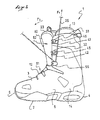
- a snowboard boot 1 is provided to accommodate the foot of the user.
- the boot 1 is a footwear element which comprises an outer sole 2 and a rod 3 secured to the sole,
- the shoe extends in length, in a longitudinal direction L, between a rear end or heel 4 and a front end or point 5, and in width, in a transverse direction W, between a lateral side 6 and a medial side 7.
- the rod 3 comprises a lower portion 10, provided to cover the foot, and a high portion 11, provided to surround the ankle and possibly the lower leg.
- the invention also applies to a footwear element comprising only a low portion.
- the rod 3 has a top 12 at the lower portion 10, and an upper end 13 or free end at the haunting portion 11, thus the shoe extends in height since the soleing external 2 to the top 12 on the side of the tip 5, and from the outer sole 2 to the upper end 13 of the side of the heel 4.
- the boot 1 is structured to allow inclinations of the lower leg during the driving of a board, a good unwinding of the foot during walking, transmissions of sensory information, and pulse transmissions for support or receptions. This is why the outer sole 2 and the rod 3 are relatively flexible.
- the rod 3 comprises a first casing 14, which constitutes the outer part of the rod 3.
- the first casing 14 thus delimits the heel 4, the tip 5, as well as the lateral 6 and medial sides 7 of the rod 3
- the rod 3 comprises a second envelope 15 inserted into the first.
- the second envelope 15 is for example a comfort slipper, removable or permanently mounted in the first envelope 14. It is however specified that the shoe 1 may be devoid of slipper, especially when the user seeks a more precise or sportier driving.
- the rod 3 consists of the first single envelope 14. This may nevertheless include an inner lining, intended to provide a minimum of comfort.
- the first envelope 14 comprises a lateral portion 21, connected to the outer sole 2 at the lateral side 6, as well as a medial portion 22, connected in turn to the outer sole 2 at the medial side 7.
- the lateral quarter 21 extends from the outer sole 2 to the top 12 of the rod 3 at the lower portion 10, remaining set back from a longitudinal plane P of the shoe or footwear element, which is median and perpendicular to the outer sole 2.
- the lateral portion 21 also remains behind the longitudinal plane P at the top portion 11.
- the medial area 22 extends from the outer sole 2 to the top 12 of the rod 3 at the lower portion 10, remaining set back from the longitudinal plane P.
- the medial area 22 also remains behind the plane Longitudinal P at the level of the upper portion 11.
- a tongue 23 which extends between the lateral 21 and medial 22.
- the footwear element 1 or shoe further comprises a reversible clamping device 25 of the lateral 21 and medial 22, which device will be described in more detail later.
- the passer 32, 33 comprises a proximal wall 34, a distal wall 35, and a bridge 36 which connects the proximal and distal walls to each other, the walls 34, 35 and the bridge 36 delimiting a guide 37 for 26.
- the proximal wall 34 is closer to the casing 14 than the distal wall 35.
- the proximal wall 34 is parallel to the casing 14 and the distal wall 35 is also parallel to the casing 14. 14, but further away by a value equal to the thickness of the bridge 36. Accordingly the distal wall 35 camber the lace 26, when in the guide 37, to move away from the casing 14 in a perpendicular direction to this one.
- the footwear element 1 comprises at least one deflector 42, 43 which extends in front of the guide 37 facing the bridge 36, so as to provide a passage 45 for the lace 26 on the side of the distal wall 35.
- the deflector deflects the lace 26 when it moves parallel to the casing 14, in a direction of penetration between the walls 34, 35 to the bridge 36. It will be better later in what conditions it can occur. In fact this architecture prevents undesired cooperation of the lace 26 with the passer. On the other hand, when the cooperation is desired, it is then sufficient to introduce the lace 26 in the loop through the passage 45, for example in a direction perpendicular to the envelope 14.
- the clamping device 25 acts on the one hand for a first clamping zone 51 and, on the other hand, for a second clamping zone 52. It is possible to obtain a first clamping level of the envelope 14 in the first zone, and a second level of tightening of the envelope 14 in the second zone. Of course, each of the levels can be chosen as the highest or the lowest. In fact, the user adjusts the tightening of each zone according to his needs.
- the first clamping zone 51 is included in the lower portion 10 of the rod 3, and the second clamping zone 52 is included in the upper portion 11.
- clamping device 25 comprises bottom loops 53, located in the lower portion 10, in particular on the lateral 21 and medial 22 quarters.
- the lace 26 travels from one quarter to the other by the loops 53, forming two strands 54, 55 intended to to join the upper end 13.
- the lace 26 loops at the passers 53 closest to the tip 5.
- the loops 53 are not described in more detail here because they are known to those skilled in the art. It is simply stated that their structure allows a free sliding of the lace 26.
- the clamping device 25 comprises one or a means for rapidly blocking each of the strands 54, 55 of the lace 26. More precisely, at the limit of the low and high portions 10 11, the footwear element 1 comprises a lateral blocker 56, clearly visible in the figures, and a medial blocking passer, not visible but arranged to be the counterpart of the lateral blocking passer in the transverse direction W.
- the footwear element 1 comprises a blocker 56.
- the lateral blocking passer 56 is a guide which has the general shape of a crescent. It is made identical or similar to that described in the document EP 0 848 917-B1 incorporated in the description by reference. However, it is specified that the blocking pass 56 comprises a body 60, made for example of plastic, having a sliding path 61 in the shape of a crescent. This path 61 is convex in its general shape, and concave in any section, to facilitate the guiding of the lace 26. It is observed that a first subdivision 62 of the path 61, placed on the side of the low loops 53 mentioned above, has a regular surface. . This makes it easy to slide the lace 26.
- a second subdivision 63 of the path 61, placed on the opposite side to the loops 53, has an irregular surface, intended to wedge, that is to say actually block, the sliding of the lace 26 along the path 61.
- the subdivision 63 has for example teeth 64 projecting inside the path 61. It is understood that a traction on the lace 26, exerted so as to spread it teeth 64, for example according to the arrow F1, allows a tensioning of the first clamping zone 51, between the front end 5 and the locking means 56. Then the drawdown of the lace 26, according to the arrow F2, in the subdivision 63, which is provided with teeth 64, allows the maintenance of clamping. Indeed, the lace 26 is stuck by the teeth: the locking effect is obtained.
- first 62 and second 63 subdivisions of the path 61 are open, in the sense that the lace 26 can be removed, but the passer 56 comprises a bridge 65 which gives the path 61 locally the appearance of a tube . This maintains the lace 26 at the blocking device, and facilitates the tightening or loosening of the first clamping zone 51.
- the clamping device 25 comprises high loops 32, 33, located in the upper portion 11 of the lateral 21 and medial 22 neighborhoods.
- the loops referenced 32, 33 are located on the lateral side 6 of the footwear element.
- other passers-by are located on the medial side 7.
- To each of the lateral passers-by 32, 33 is associated respectively a deflector 42, 43.
- This is entirely in the spirit of the invention because, because of their situation, the side loops 32, 33 are in the path of the lace 26 when it is folded to tighten the lower portion 10.
- the high loops 32, 33 are arranged between a blocking pass 56 and the upper end 13 of the rod 3.
- each strand 54, 55 of the lace 26 passes at the level of the passers 32, 33 , with the possibility of interference.
- the blocking operation could be hampered in the absence of deflectors.
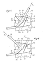
- the figure 4 shows the role of the deflector 42 during the passage of the lace 26, according to the arrow F3, at the time of tightening the lower portion 10.
- the deflector 42 moves the lace 26 away from the envelope 14, that is to say here of the lateral quarter 21. It is of course possible, conversely, to intentionally introduce the lace 26 in the loop, according to the arrow F4, as shown in FIG. figure 5 . Then the lace 26 can be stretched or blocked, as will be understood better after not only with the Figures 6 and 7 but with all of Figures 1 to 7 .
- the passage 45 between a passer 32, 33 and a deflector 42, 43, has a variable width 1. This facilitates the manual introduction of the lace in front of the guide 37. However, it may alternatively be expected that the width 1 of the passage is constant.
- the passage 45 is wider the inlet 71 of the guide 37 and, corollary, narrower at the outlet 72 of this guide 37.
- the inlet 71 is the limit of the guide facing the front end 5 or towards the lower portion 10, while the outlet 72 of the guide is oriented towards the upper end 13. This arrangement makes it easier to introduce through the passage 45 of the lace 26, especially when the latter is stressed in tension. In practice lacing is easier.
- the deflector 42, 43 has the general shape of a wedge.
- the thickness e1 of the deflector is reduced in a direction away from the passer.
- the thickness e1 of the deflector is between 90 and 110% of the thickness e2 of the passage 32, 33 at the passage 45.
- the thickness e1 of the deflector is between 0 and 20% of the thickness e2. passing in its furthest part of the passage 45, or the guide 37.
- the variation of the thickness el gives the deflector the ability to deflect the trajectory of the lace 26 during a sliding along the quarter 21 of the rod 3 .
- the guide 37 and the deflector 42, 43 form a single piece, this piece is for example made of a plastic material, metal, or any equivalent.
- the piece is secured to the casing 14 by any known means, such as riveting, gluing, or other.
- the guide 37 is convex in its general shape and concave in any section. This facilitates cooperation with the lace 26, which has for example a circular section.
- each wall 34, 35 is smooth or regular, at the point where the lace 26, that is to say in the guide 37, passes.
- a first subdivision 75 of the guide 37 has a regular surface
- a second subdivision 76 of the guide 37 has an irregular surface, for example provided with teeth 77.
- the upward pass 32, 33 is a blocking passer which functions as the passing blocker 56 which maintains the tightening of the lower portion 10. The operation of the high pass 32, 33 is not described in more detail here.
- the lace 26 is placed on all the clamping zones 51, 52.
- the footwear element comprises a locking device 80 of the two lace strands 54, 55.
- the device 80 known to man of the art, is not described in detail here. It is for example secured to the tongue 23, at the upper end 13. This facilitates the tightening of the rod 3.
- the guide 37 and the deflector 42 are two distinct elements. These are secured to the casing 14 by any known means.
- the upper portion 11 of the rod 3 comprises at least one deflector 42, 43.
- the footwear element 1 comprises two lace strands 54, 55
- the lateral portion 21 comprises at least one deflector 42, 43 which cooperates with a guide 37
- the medial quarter 22 comprises at least one deflector which cooperates with a guide.
- the invention is made from materials and according to processing techniques known to those skilled in the art.
- the guide 37 is made of a plastic material
- the deflector 42, 43 is made of a plastic material.
- baffles can be provided only on one side of the rod. It can also be expected on the lower portion.
- a rod clamping by a single yarn strand which has an attachment end to the rod and a free end.
Landscapes
- Health & Medical Sciences (AREA)
- General Health & Medical Sciences (AREA)
- Physical Education & Sports Medicine (AREA)
- Footwear And Its Accessory, Manufacturing Method And Apparatuses (AREA)
Abstract
Description
L'invention se rapporte à un élément chaussant qui comprend une enveloppe destinée à couvrir le pied. Plus particulièrement, l'invention concerne une chaussure de sport ou de marche dont la tige comprend une enveloppe. Cette chaussure peut être utilisée dans des domaines tels que le surf sur neige ou snowboard, la raquette à neige, le ski sur neige, la marche, la course sur terrain plat ou accidenté, un sport de balle, ou autre.The invention relates to a footwear element which comprises an envelope intended to cover the foot. More particularly, the invention relates to a sports shoe or walking whose stem includes an envelope. This shoe can be used in areas such as snowboarding or snowboarding, snowshoeing, snow skiing, walking, running on flat or rough terrain, a ball sport, or whatever.
Pour les utilisations envisagées, chaque chaussure comprend un semelage externe et une tige. Celle-ci comprend elle-même un quartier latéral, un quartier médial, ainsi qu'un dispositif de serrage réversible des quartiers. De manière connue cet agencement permet soit de desserrer la tige, pour chausser ou déchausser, soit au contraire de la serrer, pour maintenir le pied et parfois la cheville, voire aussi le bas de jambe.For the intended uses, each shoe includes an outer sole and a rod. It itself includes a side area, a medial area, and a reversible clamping device neighborhoods. In known manner this arrangement allows either to loosen the rod, to put on or off, or on the contrary to tighten, to maintain the foot and sometimes the ankle, or even the lower leg.
C'est le cas par exemple en snowboard, où une chaussure possède une tige qui maintient à la fois le pied, la cheville et le bas de jambe d'un utilisateur. Il est pour ce faire bien connu d'employer un dispositif de serrage qui comprend des passants associés aux quartiers et un lacet qui chemine par les passants. Le serrage du lacet amène la chaussure à assurer le maintien. Et par corollaire, bien entendu, le desserrage du lacet permet un chaussage ou un déchaussage.This is the case for example in snowboarding, where a shoe has a rod that holds both the foot, the ankle and the lower leg of a user. To this end, it is well known to employ a tightening device that includes passers-by associated with the quarters and a lace that travels through the passers-by. The tightening of the lace causes the shoe to maintain. And corollary, of course, the loosening of the lace allows a boot or a heaving.
La chaussure ci-avant présentée est adaptée à la pratique du snowboard, dans le sens où elle permet d'effectuer les mouvements ou de donner les impulsions nécessaires à la conduite d'une planche. Il est donc prévu d'optimiser la répartition de serrage : il faut que toutes les parties du pied et/ou du bas de jambe soient serrées correctement, c'est-à-dire ni en excès ni insuffisamment. Pour ce faire l'art antérieur a proposé diverses structures de dispositif de serrage, comprenant des passants et un lacet, dont la vocation est l'amélioration ou l'optimisation de la répartition des efforts de serrage de la tige d'une chaussure.The shoe presented above is adapted to the practice of snowboarding, in the sense that it allows to perform the movements or to give the impulses necessary to the driving of a board. It is therefore planned to optimize the clamping distribution: it is necessary that all the parts of the foot and / or the lower leg are tightened correctly, that is to say neither excess nor insufficiently. To do this, the prior art has proposed various clamping device structures, including loops and a lace, the purpose of which is to improve or optimize the distribution of clamping forces of the upper of a shoe.
Par exemple il est connu de prévoir deux zones de serrage pour une tige de chaussure, un même lacet agissant successivement pour une première zone de serrage puis pour une deuxième zone de serrage de la tige. Afin d'obtenir le serrage, le lacet est mis en tension au niveau de la première zone. Lorsque la tension recherchée est obtenue, par exemple par traction manuelle, cette tension est maintenue par blocage du ou des brins de lacet disposés dans la première zone. Afin de bloquer le lacet en le maintenant en tension, il est connu par exemple d'employer un passant bloqueur pour chaque brin concerné. Le passant bloqueur, tel que présenté par le document
Le mode opératoire ci-avant présenté donne satisfaction dans la mesure où, effectivement, les deux zones de serrage de la chaussure sont serrées successivement selon les besoins de l'utilisateur. Il est malgré tout apparu que ce mode opératoire, considéré en tant que tel, n'est pas toujours totalement satisfaisant.The procedure described above is satisfactory to the extent that, effectively, the two tightening zones of the shoe are tightened successively according to the needs of the user. It nevertheless appeared that this procedure, considered as such, is not always completely satisfactory.
En effet, il arrive parfois que le serrage de la première zone soit gêné par les passants de la deuxième zone. Notamment il arrive que le lacet s'introduise dans un ou plusieurs passants de la deuxième zone, alors que le serrage de la première zone n'est pas encore réalisé. L'introduction intempestive du lacet dans un passant de la deuxième zone peut se produire au moment de la mise on tension dans la première zone, ou au moment du blocage. Dans ce second cas il arrive que le rabattement d'un brin de lacet, pour obtenir le blocage, l'amène à s'introduire dans un passant de la deuxième zone. Il est alors nécessaire de faire sortir le lacet du passant, puis de reprendre l'opération de serrage de la première zone. Autrement dit la coopération non recherchée du lacet avec un passant de la deuxième zone allonge le temps nécessaire au serrage de la tige. Cette coopération non recherchée, qui se fait de manière aléatoire, rend le serrage compliqué, dans la mesure où l'utilisateur doit apporter plus d'attention, et plus de précision, dans sa gestuelle. En d'autres termes le serrage de l'élément chaussant n'est pas assez simple.Indeed, it sometimes happens that the tightening of the first zone is hampered by the passers of the second zone. In particular it happens that the lace is introduced into one or more passers of the second zone, while the tightening of the first zone is not yet achieved. The inadvertent insertion of the yaw in a passer of the second zone can occur at the moment of putting tension in the first zone, or at the time of blocking. In this second case it happens that the folding of a lace strand, to get the blockage, leads him to break into a passer of the second zone. It is then necessary to remove the lace of the passer, then resume the clamping operation of the first zone. In other words, the unwanted cooperation of the lace with a passer of the second zone lengthens the time required for clamping the rod. This unwanted cooperation, which is done randomly, makes the tightening complicated, to the extent that the user must pay more attention, and more precision, in his gestures. In other words, the tightening of the footwear element is not simple enough.
Par rapport à cela, l'invention a pour but général l'amélioration du dispositif de serrage d'une chaussure, dans le cas où ce dispositif comprend un lacet et des passants. L'un des buts de l'invention est de simplifier l'utilisation du dispositif de serrage à lacet, notamment en le rendant plus facile et plus rapide à mettre en oeuvre. Un autre but est de faire en sorte que le serrage d'une zone, ou son desserrage, ne soit pas gêné par interférence du lacet avec des éléments de la chaussure, notamment avec des passants d'une autre zone,With respect to this, the general object of the invention is the improvement of the clamping device of a shoe, in the case where this device comprises a lace and loops. One of the aims of the invention is to simplify the use of the lace clamping device, in particular by making it easier and faster to implement. Another aim is to ensure that the tightening of an area, or its loosening, is not hindered by interference of the lace with elements of the shoe, particularly with loops from another zone,
L'invention a aussi pour but d'optimiser la répartition des tensions liées au serrage de la tige. Il s'agit globalement d'obtenir une bonne répartition des tensions avec un dispositif simple, ce qui revient à concilier deux avantages contradictoires.The invention also aims to optimize the distribution of tensions related to the clamping of the rod. This is generally to obtain a good distribution of tensions with a simple device, which amounts to reconciling two contradictory advantages.
Pour ce faire, l'invention propose un élément chaussant qui comprend un semelage externe et une tige, la tige comprenant une première enveloppe, la première enveloppe comprenant un quartier latéral, un quartier médial et un dispositif de serrage réversible des quartiers latéral et médial, le dispositif de serrage comprenant un lacet et au moins un passant disposé sur l'enveloppe, le passant comprenant une paroi proximale, une paroi distale et un pont qui relie les parois proximale et distale l'une à l'autre, les parois et le pont délimitant un guide pour le lacet.To do this, the invention provides a footwear element which comprises an outer sole and a rod, the upper comprising a first casing, the first casing comprising a lateral quarter, a medial quarter and a reversible clamping device of the lateral and medial quarters, the clamp comprising a lace and at least one passer on the casing, the passer comprising a proximal wall, a distal wall and a bridge connecting the proximal and distal walls to each other, the walls and the bridge delimiting a guide for the lace.
L'élément chaussant selon l'invention est caractérisé par le fait qu'il comprend au moins un déflecteur qui s'étend devant le guide en regard du pont, de façon à ménager un passage pour le lacet du côté de la paroi distale.The footwear element according to the invention is characterized in that it comprises at least one deflector which extends in front of the guide facing the bridge, so as to provide a passage for the lace side of the distal wall.
Le déflecteur dévie le lacet, c'est-à-dire modifie sa trajectoire, lorsqu'il se déplace le long de l'enveloppe dans un sens de pénétration dans un passant. Très souvent un déplacement du lacet est son glissement sur la tige, glissement qui se produit lors de la mise en tension pour obtenir le serrage, Cela est particulièrement vrai dans le cas où la tige comprend une portion basse, prévue pour couvrir le pied, et une portion haute, prévue quant à elle pour entourer une partie du bas de jambe. Le serrage de la portion basse met le lacet en tension au niveau de cette portion basse, mais aussi le long de la portion haute. C'est au moment de la mise en tension du lacet que le risque de pénétration intempestive dans un passant de la portion haute est le plus grand. Mais le déflecteur de l'invention empêche cette pénétration, ou interférence. Il en résulte que, même lorsqu'il est tendu, le brin concerné du lacet peut être incliné et passer devant le passant sans gêne. En d'autres termes la partie tendue du lacet, qui s'étend entre un passant ou un passant bloqueur et la main, peut être déplacée librement devant d'autres passants. Un avantage qui en découle est la simplicité d'utilisation du dispositif de serrage, notamment par sa facilité et sa rapidité de mise en oeuvre.The deflector deflects the lace, that is to say, changes its path, as it moves along the envelope in a direction of penetration in a passer. Very often a displacement of the lace is its sliding on the rod, slip which occurs during the tensioning to obtain the tightening, this is particularly true in the case where the rod comprises a lower portion, provided to cover the foot, and a high portion, intended for it to surround part of the lower leg. The tightening of the lower portion makes the lace in tension at this lower portion, but also along the upper portion. It is at the moment of tensioning of the lace that the risk of inadvertent penetration into a passer of the upper portion is the largest. But the deflector of the invention prevents this penetration, or interference. As a result, even when stretched, the concerned strand of the lace can be tilted and pass in front of the passer without discomfort. In other words, the stretched portion of the lace, which extends between a passer-by or a blocking passer and the hand, can be moved freely in front of other bystanders. An advantage that arises is the simplicity of use of the clamping device, in particular by its ease and speed of implementation.
Dans le cas où le dispositif de serrage agit pour plusieurs zones, par exemple une zone basse de couverture du pied et une zone haute de tenue du bas de jambe, le serrage ou le desserrage de la zone basse n'est pas gêné par interférence du lacet avec des passants de la zone haute.In the case where the clamping device acts for several zones, for example a low zone of foot cover and a high zone of resistance of the lower leg, the tightening or loosening of the lower zone is not hindered by interference of the lace with passers of the high zone.
On remarque en complément que la répartition des tensions de serrage est optimisée. Au final, pour résumer, on peut dire que le dispositif de serrage de l'invention est une amélioration des dispositifs de l'art antérieur.It should be noted in addition that the distribution of clamping tensions is optimized. Finally, to summarize, it can be said that the clamping device of the invention is an improvement of the devices of the prior art.
D'autres caractéristiques et avantages de l'invention seront mieux compris à l'aide de la description qui va suivre, en regard du dessin annexé illustrant, selon des formes de réalisation non limitatives, comment I'invention peut être réalisée, et dans lequel :
- la
figure 1 est une vue en perspective avant d'une chaussure, selon une première forme de réalisation décrite de l'invention, - la
figure 2 est une vue de côté de la chaussure de lafigure 1 , montrant le serrage d'une portion basse de la tige, - la
figure 3 est une vue partielle de lafigure 2 , - la
figure 4 est une vue d'un passant et du déflecteur qui lui est associé, selon IV-IV de lafigure 3 , dans un cas où le lacet est déplacé le long de la tige, - la
figure 5 est similaire à lafigure 4 , dans un cas où le lacet est introduit entre le passant et le déflecteur, - la
figure 6 est une vue partielle d'un passant et d'un déflecteur situés sur une portion haute de la tige, dans un cas où le lacet est sollicité en traction pour serrer la tige, - la
figure 7 est similaire à lafigure 6 , dans un cas où le lacet est ramené dans une position de blocage, - la
figure 8 est similaire à lafigure 5 , pour une deuxième forme de réalisation de l'invention.
- the
figure 1 is a front perspective view of a shoe, according to a first described embodiment of the invention, - the
figure 2 is a side view of the shoe of thefigure 1 , showing the tightening of a lower portion of the stem, - the
figure 3 is a partial view of thefigure 2 , - the
figure 4 is a view of a passer-by and the deflector associated with it, according to IV-IV of thefigure 3 in a case where the lace is moved along the stem, - the
figure 5 is similar to thefigure 4 in a case where the lace is introduced between the passer and the deflector, - the
figure 6 is a partial view of a passer and a deflector located on an upper portion of the stem, in a case where the lace is urged in tension to tighten the rod, - the
figure 7 is similar to thefigure 6 in a case where the lace is returned to a blocking position, - the
figure 8 is similar to thefigure 5 , for a second embodiment of the invention.
Les formes de réalisation décrites après concernent par exemple des chaussures de snowboard. Cependant l'invention s'applique à d'autres domaines tels que ceux évoqués avent.The embodiments described below concern, for example, snowboard boots. However, the invention applies to other fields such as those mentioned above.
La première forme est abordée ci-après à l'aide des
Comme le montre la
Telle que représentée la tige 3 comprend une portion basse 10, prévue pour couvrir le pied, ainsi qu'une portion haute 11, prévue pour entourer la cheville et éventuellement le bas de jambe. Cependant, l'invention s'applique aussi à un élément chaussant comprenant seulement une portion basse.As shown in the
Selon la première forme de réalisation décrite, la tige 3 présente un dessus 12 au niveau de la portion basse 10, et une extrémité supérieure 13 ou extrémité libre au niveau de la portion hante 11, Ainsi la chaussure s'étend en hauteur depuis le semelage externe 2 jusqu'au dessus 12 du côté de la pointe 5, et depuis le semelage externe 2 jusqu'à l'extrémité supérieure 13 du côté du talon 4.According to the first embodiment described, the
La chaussure 1 est structurée pour permettre des inclinaisons du bas de jambe pendant la conduite d'une planche, un bon déroulement du pied pendant la marche, des transmissions d'informations sensorielles, et des transmissions d'impulsions pour des appuis ou des réceptions. C'est pourquoi le semelage externe 2 et la tige 3 sont relativement souples.The
De manière non limitative la tige 3 comprend une première enveloppe 14, laquelle constitue la partie externe de la tige 3. La première enveloppe 14 délimite donc le talon 4, la pointe 5, ainsi que les côtés latéral 6 et médial 7 de la tige 3. En complément, la tige 3 comprend une deuxième enveloppe 15 insérée dans la première. La deuxième enveloppe 15 est par exemple un chausson de confort, amovible ou monté à demeure dans la première enveloppe 14. On précise toutefois que la chaussure 1 peut être dépourvue de chausson, notamment lorsque l'utilisateur recherche une conduite plus précise ou plus sportive. Dans ce cas la tige 3 est constituée de la seule première enveloppe 14. Celle-ci peut néanmoins comprendre une doublure interna, destinée à apporter un minimum de confort.In a nonlimiting manner, the
La première enveloppe 14 comprend un quartier latéral 21, relié au semelage externe 2 au niveau du côté latéral 6, ainsi qu'un quartier médial 22, relié quant à lui au semelage externe 2 au niveau du côté médial 7.The
De manière non limitative, comme on le considère sur les
L'élément chaussant 1 ou chaussure comprend encore un dispositif de serrage réversible 25 des quartiers latéral 21 et médial 22, dispositif qui sera décrit plus en détail après. On peut néanmoins déjà préciser qu'il 25 comprend un lacet 26 et au moins un passant 32, 33 disposé sur la première enveloppe 14. Comme on peut s'en rendre compte à l'aide des
Selon l'invention, l'élément chaussant 1 comprend au moins un déflecteur 42, 43 qui s'étend devant le guide 37 en regard du pont 36, de façon à ménager un passage 45 pour le lacet 26 du côté de la paroi distale 35. Le déflecteur dévie le lacet 26 lorsqu'il se déplace parallèlement à l'enveloppe 14, dans un sens de pénétration entre les parois 34, 35 vers le pont 36. On verra mieux par la suite dans quelles conditions cela peut se produire. En fait cette architecture empêche une coopération non souhaitée du lacet 26 avec le passant. A contrario, lorsque la coopération est désirée, il suffit alors d'introduire le lacet 26 dans le passant par le passage 45, par exemple selon une direction perpendiculaire à l'enveloppe 14.According to the invention, the
Afin de mieux mettre en valeur le rôle du déflecteur 42, 43 selon l'invention il est utile maintenant, comme évoqué avant, de décrire plus en détail le dispositif de serrage réversible 25.In order to better highlight the role of the
Comme on le perçoit à l'aide des
Selon la première forme de réalisation décrite, de manière non limitative, la première zone de serrage 51 est comprise dans la portion basse 10 de la tige 3, et la deuxième zone de serrage 52 est comprise dans la portion haute 11. En corrélation le dispositif de serrage 25 comprend des passants bas 53, situés dans la portion basse 10 notamment sur les quartiers latéral 21 et médial 22. Le lacet 26 chemine d'un quartier à l'autre par les passants 53, en formant deux brins 54, 55 destinés à rejoindre l'extrémité supérieure 13. Par corollaire, le lacet 26 forme une boucle au niveau des passants 53 les plus proches de la pointe 5. Les passants bas 53 ne sont pas décrits plus en détail ici car ils sont connus de l'homme du métier. On précise simplement que leur structure permet un libre coulissement du lacet 26.According to the first embodiment described, in a nonlimiting manner, the
Afin de pouvoir serrer la première zone de serrage 51 de manière réversible, le dispositif de serrage 25 comprend un ou des moyens de blocage rapide de chacun des brins 54, 55 du lacet 26. Plus précisément, à la limite des portions basse 10 et haute 11, l'élément chaussant 1 comprend un passant bloqueur latéral 56, bien visible sur les figures, ainsi qu'un passant bloqueur médial, non visible mais disposé pour être le pendant du passant bloqueur latéral selon la direction transversale W.In order to be able to clamp the
L'emploi de deux passants bloqueurs est dû à la nécessité de serrer deux brins 54, 55 du lacet 26. Si ce dernier s'était étendu depuis une extrémité d'attache vers une seule extrémité libre, il aurait suffi d'un seul passant bloqueur. Dans tous les cas, à la limite des portions basse 10 et haute 11, l'élément chaussant 1 comprend un passant bloqueur 56.The use of two blocking loops is due to the need to tighten two
Comme le montre la
Ensuite le dispositif de serrage 25 comprend des passants hauts 32, 33, situés dans la portion haute 11 sur les quartiers latéral 21 et médial 22. Les passants référencés 32, 33 sont situés du côté latéral 6 de l'élément chaussant. Dans le même esprit, bien qu'ils ne soient pas visibles, d'autres passants sont situés du côté médial 7. A chacun des passants latéraux 32, 33 est associé respectivement un déflecteur 42, 43. Cela correspond tout à fait à l'esprit de l'invention car, de par leur situation, les passants latéraux 32, 33 sont sur la trajectoire du lacet 26 lorsque celui-ci est rabattu pour serrer la portion basse 10. En effet, les passants hauts 32, 33 sont disposés entre un passant bloqueur 56 et l'extrémité supérieure 13 de la tige 3. L'opération de blocage des brins 54, 55 du lacet 26 se traduit par un glissement de ce dernier sur le quartier latéral 21 ou sur le quartier médial 22, glissement dû à un pivotement selon un axe matérialisé par le passant bloqueur 56. Lors du glissement, chaque brin 54, 55 du lacet 26 passe à hauteur des passants 32, 33, avec l'éventualité d'une interférence. L'opération de blocage pourrait donc être gênée en l'absence des déflecteurs.Then the clamping
La
On observe que le passage 45, entre un passant 32, 33 et un déflecteur 42, 43, présente une largeur 1 variable. Cela facilite l'introduction manuelle du lacet en face du guide 37. Cependant, il peut alternativement être prévu que la largeur 1 du passage soit constante.It is observed that the
Il est par exemple prévu que le passage 45 est plus large l'entrée 71 du guide 37 et, par corollaire, plus étroit à la sortie 72 de ce guide 37. L'entrée 71 est la limite du guide orientée vers l'extrémité avant 5 ou vers la portion basse 10, tandis que la sortie 72 du guide est orientée vers l'extrémité supérieure 13. Cet agencement rend plus facile l'introduction par le passage 45 du lacet 26, notamment lorsque celui-ci est sollicité en traction. En pratique le laçage est plus facile.It is for example provided that the
On observe encore, notamment sur les
L'ensemble des
De manière non limitative, le guide 37 et le déflecteur 42, 43 forment une pièce monobloc, Cette pièce est par exemple constituée d'une matière plastique, métallique, ou de tout équivalent. La pièce est solidarisée à l'enveloppe 14 par tout moyen connu, comme un rivetage, un collage, ou autre.In a nonlimiting manner, the
Comme on le comprend à l'aide des
En référence aux
Il peut être prévu que chaque paroi 34, 35 soit lisse ou régulière, à l'endroit où passe le lacet 26, c'est-à-dire dans le guide 37. Cependant, comme le montrent les
Au final, comme on le comprend à l'aide des
La deuxième forme de réalisation est maintenant présentée à l'aide de la
Ce qui est spécifique à la deuxième forme de réalisation de l'invention, c'est que le guide 37 et le déflecteur 42 sont deux éléments distincts. Ceux-ci sont solidarisés à l'enveloppe 14 par tout moyen connu.What is specific to the second embodiment of the invention is that the
Pour chaque forme de réalisation présentée la portion haute 11 de la tige 3 comprend au moins un déflecteur 42, 43. Pour chaque forme toujours, l'élément chaussant 1 comprend deux brins de lacet 54, 55, le quartier latéral 21 comprend au moins un déflecteur 42, 43 qui coopère avec un guide 37, et le quartier médial 22 comprend au moins un déflecteur qui coopère avec un guide.For each embodiment shown, the
Dans tous les cas l'invention est réalisée à partir de matériaux et selon des techniques de mise en oeuvre connus de l'homme du métier. Par exemple, le guide 37 est constitué d'une matière plastique, et le déflecteur 42, 43 est constitué d'une matière plastique.In all cases the invention is made from materials and according to processing techniques known to those skilled in the art. For example, the
Bien entendu l'invention n'est pas limitée aux formes de réalisation ci-avant décrites, et comprend tous les équivalents techniques pouvant entrer dans la portée des revendications qui vont suive,Naturally, the invention is not limited to the embodiments described above, and includes all the technical equivalents that fall within the scope of the following claims,
Par exempte, on peut prévoir des déflecteurs seulement d'un côté de la tige. On peut aussi en prévoir sur la portion basse.For example, baffles can be provided only on one side of the rod. It can also be expected on the lower portion.
Encore, il peut être prévu un serrage de tige par un brin de lacet unique, lequel présente une extrémité d'attache à la tige et une extrémité libre.Still, there can be provided a rod clamping by a single yarn strand, which has an attachment end to the rod and a free end.
Claims (16)
caractérisé par le fait qu'il comprend au moins un déflecteur (42, 43) qui s'étend devant le guide (37) en regard du pont (36), de façon à ménager un passage (45) pour le lacet (26) du côté de la paroi distale (35).Footwear element (1) which comprises an outer sole (2) and a rod (3), the upper (3) comprising a first casing (14), the first casing (14) comprising a lateral quarter (21), a medial quarter (22) and a reversible clamping device (25) of the lateral (21) and medial (22) quarters, the clamping device (25) comprising a lace (26) and at least one passer (32, 33) disposed on the casing (14), the loop (32, 33) comprising a proximal wall (34), a distal wall (35) and a bridge (36) which connects the proximal (34) and distal (35) walls, one to the other, the walls (34, 35) and the bridge (36) delimiting a guide (37) for the lace (26),
characterized in that it comprises at least one deflector (42, 43) extending in front of the guide (37) facing the bridge (36), so as to provide a passage (45) for the lace (26) on the side of the distal wall (35).
Applications Claiming Priority (1)
| Application Number | Priority Date | Filing Date | Title |
|---|---|---|---|
| FR1104039A FR2984694B1 (en) | 2011-12-22 | 2011-12-22 | FOOTWEAR WITH AN IMPROVED TIGHTENING DEVICE |
Publications (1)
| Publication Number | Publication Date |
|---|---|
| EP2606760A1 true EP2606760A1 (en) | 2013-06-26 |
Family
ID=47358586
Family Applications (1)
| Application Number | Title | Priority Date | Filing Date |
|---|---|---|---|
| EP12008463.7A Withdrawn EP2606760A1 (en) | 2011-12-22 | 2012-12-20 | Fitting element provided with an improved tightening device |
Country Status (2)
| Country | Link |
|---|---|
| EP (1) | EP2606760A1 (en) |
| FR (1) | FR2984694B1 (en) |
Cited By (5)
| Publication number | Priority date | Publication date | Assignee | Title |
|---|---|---|---|---|
| WO2021068166A1 (en) * | 2019-10-10 | 2021-04-15 | 孙寅贵 | Boot suitable for skiing and general use |
| WO2021076439A1 (en) * | 2019-10-18 | 2021-04-22 | Nike Innovate C.V. | Lock for an adjustment cord of a wearable article |
| US11096450B2 (en) | 2019-10-25 | 2021-08-24 | Perry Leonfellner | Lace lock system |
| US11589653B2 (en) | 2019-11-25 | 2023-02-28 | Nike, Inc. | Tension-retaining system for a wearable article |
| US11707113B2 (en) | 2019-10-18 | 2023-07-25 | Nike, Inc. | Easy-access article of footwear with cord lock |
Citations (5)
| Publication number | Priority date | Publication date | Assignee | Title |
|---|---|---|---|---|
| FR2757026A1 (en) | 1996-12-17 | 1998-06-19 | Salomon Sa | BLOCKER ASSEMBLY |
| WO2001047386A1 (en) * | 1999-12-28 | 2001-07-05 | Salomon S.A. | Tight shoe lace-up device |
| WO2009103224A1 (en) * | 2008-02-21 | 2009-08-27 | Liu Hsing-Chyi | Control device for tightening or loosening a shoelace and shoes |
| EP2250920A1 (en) * | 2008-02-21 | 2010-11-17 | Guangzhou Her Sheng Footwear Co., Ltd. | Shoelace fastener and shoe |
| DE202011106009U1 (en) * | 2011-09-22 | 2011-11-10 | JACK WOLFSKIN Ausrüstung für Draussen GmbH & Co. KGaA | Lace-up hook for guiding a drawstring |
-
2011
- 2011-12-22 FR FR1104039A patent/FR2984694B1/en not_active Expired - Fee Related
-
2012
- 2012-12-20 EP EP12008463.7A patent/EP2606760A1/en not_active Withdrawn
Patent Citations (6)
| Publication number | Priority date | Publication date | Assignee | Title |
|---|---|---|---|---|
| FR2757026A1 (en) | 1996-12-17 | 1998-06-19 | Salomon Sa | BLOCKER ASSEMBLY |
| EP0848917B1 (en) | 1996-12-17 | 2000-04-19 | Salomon S.A. | Blocking device |
| WO2001047386A1 (en) * | 1999-12-28 | 2001-07-05 | Salomon S.A. | Tight shoe lace-up device |
| WO2009103224A1 (en) * | 2008-02-21 | 2009-08-27 | Liu Hsing-Chyi | Control device for tightening or loosening a shoelace and shoes |
| EP2250920A1 (en) * | 2008-02-21 | 2010-11-17 | Guangzhou Her Sheng Footwear Co., Ltd. | Shoelace fastener and shoe |
| DE202011106009U1 (en) * | 2011-09-22 | 2011-11-10 | JACK WOLFSKIN Ausrüstung für Draussen GmbH & Co. KGaA | Lace-up hook for guiding a drawstring |
Cited By (6)
| Publication number | Priority date | Publication date | Assignee | Title |
|---|---|---|---|---|
| WO2021068166A1 (en) * | 2019-10-10 | 2021-04-15 | 孙寅贵 | Boot suitable for skiing and general use |
| WO2021076439A1 (en) * | 2019-10-18 | 2021-04-22 | Nike Innovate C.V. | Lock for an adjustment cord of a wearable article |
| US11439203B2 (en) | 2019-10-18 | 2022-09-13 | Nike, Inc. | Lock for an adjustment cord of a wearable article |
| US11707113B2 (en) | 2019-10-18 | 2023-07-25 | Nike, Inc. | Easy-access article of footwear with cord lock |
| US11096450B2 (en) | 2019-10-25 | 2021-08-24 | Perry Leonfellner | Lace lock system |
| US11589653B2 (en) | 2019-11-25 | 2023-02-28 | Nike, Inc. | Tension-retaining system for a wearable article |
Also Published As
| Publication number | Publication date |
|---|---|
| FR2984694B1 (en) | 2014-01-10 |
| FR2984694A1 (en) | 2013-06-28 |
Similar Documents
| Publication | Publication Date | Title |
|---|---|---|
| EP2314177B1 (en) | Boot with improved leg tightening | |
| EP1769692B1 (en) | Shoe which enhances the retaining of the heel | |
| EP1156723B1 (en) | Tight shoe lace-up device | |
| EP1769693B1 (en) | Shoe which enhances tightening of the upper | |
| EP2604136B1 (en) | Boot with improved leg tightening | |
| EP2052636B1 (en) | Boot with improved leg tightening | |
| EP2524610A1 (en) | Device for blocking strands of yarn | |
| EP2060196B1 (en) | Boot with improved leg tightening | |
| EP1688055A1 (en) | Sports shoe | |
| EP2606760A1 (en) | Fitting element provided with an improved tightening device | |
| EP2580978A1 (en) | Schuh mit verbesserter Einspannmöglichkeit des Schafts | |
| CA2729398A1 (en) | Footwear with improved upper | |
| EP2580980A1 (en) | Schuh mit verbessertem Schaft | |
| EP2620071B1 (en) | Footwear element provided with an improved tightening device | |
| EP2481315B1 (en) | Fitting element provided with an improved tightening device | |
| WO1993025107A1 (en) | Shoe with foot retaining device | |
| EP3510886B1 (en) | Footwear in which the upper includes a top portion | |
| EP2989917B1 (en) | Sports shoe | |
| EP2617311A1 (en) | Fitting element provided with an improved tightening device | |
| EP2620070A1 (en) | Footwear element provided with an improved tightening device | |
| EP2481314A1 (en) | Footwear in which the upper includes a top portion | |
| FR3046914A1 (en) | SHOE PROVIDED WITH TWO CLAMPING DEVICES |
Legal Events
| Date | Code | Title | Description |
|---|---|---|---|
| AK | Designated contracting states |
Kind code of ref document: A1 Designated state(s): AL AT BE BG CH CY CZ DE DK EE ES FI FR GB GR HR HU IE IS IT LI LT LU LV MC MK MT NL NO PL PT RO RS SE SI SK SM TR |
|
| AX | Request for extension of the european patent |
Extension state: BA ME |
|
| PUAI | Public reference made under article 153(3) epc to a published international application that has entered the european phase |
Free format text: ORIGINAL CODE: 0009012 |
|
| 17P | Request for examination filed |
Effective date: 20131217 |
|
| STAA | Information on the status of an ep patent application or granted ep patent |
Free format text: STATUS: THE APPLICATION IS DEEMED TO BE WITHDRAWN |
|
| 18D | Application deemed to be withdrawn |
Effective date: 20160701 |