EP2606760A1 - Schuhelement, das mit einer verbesserten Festziehvorrichtung ausgestattet ist - Google Patents
Schuhelement, das mit einer verbesserten Festziehvorrichtung ausgestattet ist Download PDFInfo
- Publication number
- EP2606760A1 EP2606760A1 EP12008463.7A EP12008463A EP2606760A1 EP 2606760 A1 EP2606760 A1 EP 2606760A1 EP 12008463 A EP12008463 A EP 12008463A EP 2606760 A1 EP2606760 A1 EP 2606760A1
- Authority
- EP
- European Patent Office
- Prior art keywords
- guide
- lace
- deflector
- footwear
- rod
- Prior art date
- Legal status (The legal status is an assumption and is not a legal conclusion. Google has not performed a legal analysis and makes no representation as to the accuracy of the status listed.)
- Withdrawn
Links
Images


Classifications
-
- A—HUMAN NECESSITIES
- A43—FOOTWEAR
- A43B—CHARACTERISTIC FEATURES OF FOOTWEAR; PARTS OF FOOTWEAR
- A43B5/00—Footwear for sporting purposes
- A43B5/04—Ski or like boots
- A43B5/0401—Snowboard boots
-
- A—HUMAN NECESSITIES
- A43—FOOTWEAR
- A43C—FASTENINGS OR ATTACHMENTS OF FOOTWEAR; LACES IN GENERAL
- A43C3/00—Hooks for laces; Guards for hooks
Definitions
- the invention relates to a footwear element which comprises an envelope intended to cover the foot. More particularly, the invention relates to a sports shoe or walking whose stem includes an envelope. This shoe can be used in areas such as snowboarding or snowboarding, snowshoeing, snow skiing, walking, running on flat or rough terrain, a ball sport, or whatever.
- each shoe includes an outer sole and a rod. It itself includes a side area, a medial area, and a reversible clamping device neighborhoods. In known manner this arrangement allows either to loosen the rod, to put on or off, or on the contrary to tighten, to maintain the foot and sometimes the ankle, or even the lower leg.
- the shoe presented above is adapted to the practice of snowboarding, in the sense that it allows to perform the movements or to give the impulses necessary to the driving of a board. It is therefore planned to optimize the clamping distribution: it is necessary that all the parts of the foot and / or the lower leg are tightened correctly, that is to say neither excess nor insufficiently.
- the prior art has proposed various clamping device structures, including loops and a lace, the purpose of which is to improve or optimize the distribution of clamping forces of the upper of a shoe.
- the tightening of the first zone is hampered by the passers of the second zone.
- the lace is introduced into one or more passers of the second zone, while the tightening of the first zone is not yet achieved.
- the inadvertent insertion of the yaw in a passer of the second zone can occur at the moment of putting tension in the first zone, or at the time of blocking.
- the folding of a lace strand, to get the blockage leads him to break into a passer of the second zone. It is then necessary to remove the lace of the passer, then resume the clamping operation of the first zone.
- the unwanted cooperation of the lace with a passer of the second zone lengthens the time required for clamping the rod.
- This unwanted cooperation which is done randomly, makes the tightening complicated, to the extent that the user must pay more attention, and more precision, in his gestures. In other words, the tightening of the footwear element is not simple enough.
- the general object of the invention is the improvement of the clamping device of a shoe, in the case where this device comprises a lace and loops.
- One of the aims of the invention is to simplify the use of the lace clamping device, in particular by making it easier and faster to implement.
- Another aim is to ensure that the tightening of an area, or its loosening, is not hindered by interference of the lace with elements of the shoe, particularly with loops from another zone,
- the invention also aims to optimize the distribution of tensions related to the clamping of the rod. This is generally to obtain a good distribution of tensions with a simple device, which amounts to reconciling two contradictory advantages.
- the invention provides a footwear element which comprises an outer sole and a rod, the upper comprising a first casing, the first casing comprising a lateral quarter, a medial quarter and a reversible clamping device of the lateral and medial quarters, the clamp comprising a lace and at least one passer on the casing, the passer comprising a proximal wall, a distal wall and a bridge connecting the proximal and distal walls to each other, the walls and the bridge delimiting a guide for the lace.
- the footwear element according to the invention is characterized in that it comprises at least one deflector which extends in front of the guide facing the bridge, so as to provide a passage for the lace side of the distal wall.
- the deflector deflects the lace, that is to say, changes its path, as it moves along the envelope in a direction of penetration in a passer.
- a displacement of the lace is its sliding on the rod, slip which occurs during the tensioning to obtain the tightening, this is particularly true in the case where the rod comprises a lower portion, provided to cover the foot, and a high portion, intended for it to surround part of the lower leg.
- the tightening of the lower portion makes the lace in tension at this lower portion, but also along the upper portion. It is at the moment of tensioning of the lace that the risk of inadvertent penetration into a passer of the upper portion is the largest. But the deflector of the invention prevents this penetration, or interference.
- the concerned strand of the lace can be tilted and pass in front of the passer without discomfort.
- the stretched portion of the lace which extends between a passer-by or a blocking passer and the hand, can be moved freely in front of other bystanders.
- the clamping device acts for several zones, for example a low zone of foot cover and a high zone of resistance of the lower leg, the tightening or loosening of the lower zone is not hindered by interference of the lace with passers of the high zone.
- clamping device of the invention is an improvement of the devices of the prior art.
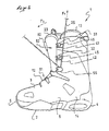
- a snowboard boot 1 is provided to accommodate the foot of the user.
- the boot 1 is a footwear element which comprises an outer sole 2 and a rod 3 secured to the sole,
- the shoe extends in length, in a longitudinal direction L, between a rear end or heel 4 and a front end or point 5, and in width, in a transverse direction W, between a lateral side 6 and a medial side 7.
- the rod 3 comprises a lower portion 10, provided to cover the foot, and a high portion 11, provided to surround the ankle and possibly the lower leg.
- the invention also applies to a footwear element comprising only a low portion.
- the rod 3 has a top 12 at the lower portion 10, and an upper end 13 or free end at the haunting portion 11, thus the shoe extends in height since the soleing external 2 to the top 12 on the side of the tip 5, and from the outer sole 2 to the upper end 13 of the side of the heel 4.
- the boot 1 is structured to allow inclinations of the lower leg during the driving of a board, a good unwinding of the foot during walking, transmissions of sensory information, and pulse transmissions for support or receptions. This is why the outer sole 2 and the rod 3 are relatively flexible.
- the rod 3 comprises a first casing 14, which constitutes the outer part of the rod 3.
- the first casing 14 thus delimits the heel 4, the tip 5, as well as the lateral 6 and medial sides 7 of the rod 3
- the rod 3 comprises a second envelope 15 inserted into the first.
- the second envelope 15 is for example a comfort slipper, removable or permanently mounted in the first envelope 14. It is however specified that the shoe 1 may be devoid of slipper, especially when the user seeks a more precise or sportier driving.
- the rod 3 consists of the first single envelope 14. This may nevertheless include an inner lining, intended to provide a minimum of comfort.
- the first envelope 14 comprises a lateral portion 21, connected to the outer sole 2 at the lateral side 6, as well as a medial portion 22, connected in turn to the outer sole 2 at the medial side 7.
- the lateral quarter 21 extends from the outer sole 2 to the top 12 of the rod 3 at the lower portion 10, remaining set back from a longitudinal plane P of the shoe or footwear element, which is median and perpendicular to the outer sole 2.
- the lateral portion 21 also remains behind the longitudinal plane P at the top portion 11.
- the medial area 22 extends from the outer sole 2 to the top 12 of the rod 3 at the lower portion 10, remaining set back from the longitudinal plane P.
- the medial area 22 also remains behind the plane Longitudinal P at the level of the upper portion 11.
- a tongue 23 which extends between the lateral 21 and medial 22.
- the footwear element 1 or shoe further comprises a reversible clamping device 25 of the lateral 21 and medial 22, which device will be described in more detail later.
- the passer 32, 33 comprises a proximal wall 34, a distal wall 35, and a bridge 36 which connects the proximal and distal walls to each other, the walls 34, 35 and the bridge 36 delimiting a guide 37 for 26.
- the proximal wall 34 is closer to the casing 14 than the distal wall 35.
- the proximal wall 34 is parallel to the casing 14 and the distal wall 35 is also parallel to the casing 14. 14, but further away by a value equal to the thickness of the bridge 36. Accordingly the distal wall 35 camber the lace 26, when in the guide 37, to move away from the casing 14 in a perpendicular direction to this one.
- the footwear element 1 comprises at least one deflector 42, 43 which extends in front of the guide 37 facing the bridge 36, so as to provide a passage 45 for the lace 26 on the side of the distal wall 35.
- the deflector deflects the lace 26 when it moves parallel to the casing 14, in a direction of penetration between the walls 34, 35 to the bridge 36. It will be better later in what conditions it can occur. In fact this architecture prevents undesired cooperation of the lace 26 with the passer. On the other hand, when the cooperation is desired, it is then sufficient to introduce the lace 26 in the loop through the passage 45, for example in a direction perpendicular to the envelope 14.
- the clamping device 25 acts on the one hand for a first clamping zone 51 and, on the other hand, for a second clamping zone 52. It is possible to obtain a first clamping level of the envelope 14 in the first zone, and a second level of tightening of the envelope 14 in the second zone. Of course, each of the levels can be chosen as the highest or the lowest. In fact, the user adjusts the tightening of each zone according to his needs.
- the first clamping zone 51 is included in the lower portion 10 of the rod 3, and the second clamping zone 52 is included in the upper portion 11.
- clamping device 25 comprises bottom loops 53, located in the lower portion 10, in particular on the lateral 21 and medial 22 quarters.
- the lace 26 travels from one quarter to the other by the loops 53, forming two strands 54, 55 intended to to join the upper end 13.
- the lace 26 loops at the passers 53 closest to the tip 5.
- the loops 53 are not described in more detail here because they are known to those skilled in the art. It is simply stated that their structure allows a free sliding of the lace 26.
- the clamping device 25 comprises one or a means for rapidly blocking each of the strands 54, 55 of the lace 26. More precisely, at the limit of the low and high portions 10 11, the footwear element 1 comprises a lateral blocker 56, clearly visible in the figures, and a medial blocking passer, not visible but arranged to be the counterpart of the lateral blocking passer in the transverse direction W.
- the footwear element 1 comprises a blocker 56.
- the lateral blocking passer 56 is a guide which has the general shape of a crescent. It is made identical or similar to that described in the document EP 0 848 917-B1 incorporated in the description by reference. However, it is specified that the blocking pass 56 comprises a body 60, made for example of plastic, having a sliding path 61 in the shape of a crescent. This path 61 is convex in its general shape, and concave in any section, to facilitate the guiding of the lace 26. It is observed that a first subdivision 62 of the path 61, placed on the side of the low loops 53 mentioned above, has a regular surface. . This makes it easy to slide the lace 26.
- a second subdivision 63 of the path 61, placed on the opposite side to the loops 53, has an irregular surface, intended to wedge, that is to say actually block, the sliding of the lace 26 along the path 61.
- the subdivision 63 has for example teeth 64 projecting inside the path 61. It is understood that a traction on the lace 26, exerted so as to spread it teeth 64, for example according to the arrow F1, allows a tensioning of the first clamping zone 51, between the front end 5 and the locking means 56. Then the drawdown of the lace 26, according to the arrow F2, in the subdivision 63, which is provided with teeth 64, allows the maintenance of clamping. Indeed, the lace 26 is stuck by the teeth: the locking effect is obtained.
- first 62 and second 63 subdivisions of the path 61 are open, in the sense that the lace 26 can be removed, but the passer 56 comprises a bridge 65 which gives the path 61 locally the appearance of a tube . This maintains the lace 26 at the blocking device, and facilitates the tightening or loosening of the first clamping zone 51.
- the clamping device 25 comprises high loops 32, 33, located in the upper portion 11 of the lateral 21 and medial 22 neighborhoods.
- the loops referenced 32, 33 are located on the lateral side 6 of the footwear element.
- other passers-by are located on the medial side 7.
- To each of the lateral passers-by 32, 33 is associated respectively a deflector 42, 43.
- This is entirely in the spirit of the invention because, because of their situation, the side loops 32, 33 are in the path of the lace 26 when it is folded to tighten the lower portion 10.
- the high loops 32, 33 are arranged between a blocking pass 56 and the upper end 13 of the rod 3.
- each strand 54, 55 of the lace 26 passes at the level of the passers 32, 33 , with the possibility of interference.
- the blocking operation could be hampered in the absence of deflectors.
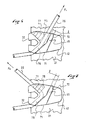
- the figure 4 shows the role of the deflector 42 during the passage of the lace 26, according to the arrow F3, at the time of tightening the lower portion 10.
- the deflector 42 moves the lace 26 away from the envelope 14, that is to say here of the lateral quarter 21. It is of course possible, conversely, to intentionally introduce the lace 26 in the loop, according to the arrow F4, as shown in FIG. figure 5 . Then the lace 26 can be stretched or blocked, as will be understood better after not only with the Figures 6 and 7 but with all of Figures 1 to 7 .
- the passage 45 between a passer 32, 33 and a deflector 42, 43, has a variable width 1. This facilitates the manual introduction of the lace in front of the guide 37. However, it may alternatively be expected that the width 1 of the passage is constant.
- the passage 45 is wider the inlet 71 of the guide 37 and, corollary, narrower at the outlet 72 of this guide 37.
- the inlet 71 is the limit of the guide facing the front end 5 or towards the lower portion 10, while the outlet 72 of the guide is oriented towards the upper end 13. This arrangement makes it easier to introduce through the passage 45 of the lace 26, especially when the latter is stressed in tension. In practice lacing is easier.
- the deflector 42, 43 has the general shape of a wedge.
- the thickness e1 of the deflector is reduced in a direction away from the passer.
- the thickness e1 of the deflector is between 90 and 110% of the thickness e2 of the passage 32, 33 at the passage 45.
- the thickness e1 of the deflector is between 0 and 20% of the thickness e2. passing in its furthest part of the passage 45, or the guide 37.
- the variation of the thickness el gives the deflector the ability to deflect the trajectory of the lace 26 during a sliding along the quarter 21 of the rod 3 .
- the guide 37 and the deflector 42, 43 form a single piece, this piece is for example made of a plastic material, metal, or any equivalent.
- the piece is secured to the casing 14 by any known means, such as riveting, gluing, or other.
- the guide 37 is convex in its general shape and concave in any section. This facilitates cooperation with the lace 26, which has for example a circular section.
- each wall 34, 35 is smooth or regular, at the point where the lace 26, that is to say in the guide 37, passes.
- a first subdivision 75 of the guide 37 has a regular surface
- a second subdivision 76 of the guide 37 has an irregular surface, for example provided with teeth 77.
- the upward pass 32, 33 is a blocking passer which functions as the passing blocker 56 which maintains the tightening of the lower portion 10. The operation of the high pass 32, 33 is not described in more detail here.
- the lace 26 is placed on all the clamping zones 51, 52.
- the footwear element comprises a locking device 80 of the two lace strands 54, 55.
- the device 80 known to man of the art, is not described in detail here. It is for example secured to the tongue 23, at the upper end 13. This facilitates the tightening of the rod 3.
- the guide 37 and the deflector 42 are two distinct elements. These are secured to the casing 14 by any known means.
- the upper portion 11 of the rod 3 comprises at least one deflector 42, 43.
- the footwear element 1 comprises two lace strands 54, 55
- the lateral portion 21 comprises at least one deflector 42, 43 which cooperates with a guide 37
- the medial quarter 22 comprises at least one deflector which cooperates with a guide.
- the invention is made from materials and according to processing techniques known to those skilled in the art.
- the guide 37 is made of a plastic material
- the deflector 42, 43 is made of a plastic material.
- baffles can be provided only on one side of the rod. It can also be expected on the lower portion.
- a rod clamping by a single yarn strand which has an attachment end to the rod and a free end.
Landscapes
- Health & Medical Sciences (AREA)
- General Health & Medical Sciences (AREA)
- Physical Education & Sports Medicine (AREA)
- Footwear And Its Accessory, Manufacturing Method And Apparatuses (AREA)
Applications Claiming Priority (1)
| Application Number | Priority Date | Filing Date | Title |
|---|---|---|---|
| FR1104039A FR2984694B1 (fr) | 2011-12-22 | 2011-12-22 | Element chaussant muni d'un dispositif de serrage ameliore |
Publications (1)
| Publication Number | Publication Date |
|---|---|
| EP2606760A1 true EP2606760A1 (de) | 2013-06-26 |
Family
ID=47358586
Family Applications (1)
| Application Number | Title | Priority Date | Filing Date |
|---|---|---|---|
| EP12008463.7A Withdrawn EP2606760A1 (de) | 2011-12-22 | 2012-12-20 | Schuhelement, das mit einer verbesserten Festziehvorrichtung ausgestattet ist |
Country Status (2)
| Country | Link |
|---|---|
| EP (1) | EP2606760A1 (de) |
| FR (1) | FR2984694B1 (de) |
Cited By (5)
| Publication number | Priority date | Publication date | Assignee | Title |
|---|---|---|---|---|
| WO2021068166A1 (zh) * | 2019-10-10 | 2021-04-15 | 孙寅贵 | 通用于滑雪和日常生活的靴子 |
| WO2021076439A1 (en) * | 2019-10-18 | 2021-04-22 | Nike Innovate C.V. | Lock for an adjustment cord of a wearable article |
| US11096450B2 (en) | 2019-10-25 | 2021-08-24 | Perry Leonfellner | Lace lock system |
| US11589653B2 (en) | 2019-11-25 | 2023-02-28 | Nike, Inc. | Tension-retaining system for a wearable article |
| US11707113B2 (en) | 2019-10-18 | 2023-07-25 | Nike, Inc. | Easy-access article of footwear with cord lock |
Citations (5)
| Publication number | Priority date | Publication date | Assignee | Title |
|---|---|---|---|---|
| FR2757026A1 (fr) | 1996-12-17 | 1998-06-19 | Salomon Sa | Ensemble bloqueur |
| WO2001047386A1 (fr) * | 1999-12-28 | 2001-07-05 | Salomon S.A. | Dispositif de serrage de puissance d'une chaussure |
| WO2009103224A1 (zh) * | 2008-02-21 | 2009-08-27 | Liu Hsing-Chyi | 鞋带松紧控制装置及鞋子 |
| EP2250920A1 (de) * | 2008-02-21 | 2010-11-17 | Guangzhou Her Sheng Footwear Co., Ltd. | Schnürsenkelbindevorrichtung und schuh |
| DE202011106009U1 (de) * | 2011-09-22 | 2011-11-10 | JACK WOLFSKIN Ausrüstung für Draussen GmbH & Co. KGaA | Schnürhaken zum Führen eines Zugbandes |
-
2011
- 2011-12-22 FR FR1104039A patent/FR2984694B1/fr not_active Expired - Fee Related
-
2012
- 2012-12-20 EP EP12008463.7A patent/EP2606760A1/de not_active Withdrawn
Patent Citations (6)
| Publication number | Priority date | Publication date | Assignee | Title |
|---|---|---|---|---|
| FR2757026A1 (fr) | 1996-12-17 | 1998-06-19 | Salomon Sa | Ensemble bloqueur |
| EP0848917B1 (de) | 1996-12-17 | 2000-04-19 | Salomon S.A. | Blockiervorrichtung |
| WO2001047386A1 (fr) * | 1999-12-28 | 2001-07-05 | Salomon S.A. | Dispositif de serrage de puissance d'une chaussure |
| WO2009103224A1 (zh) * | 2008-02-21 | 2009-08-27 | Liu Hsing-Chyi | 鞋带松紧控制装置及鞋子 |
| EP2250920A1 (de) * | 2008-02-21 | 2010-11-17 | Guangzhou Her Sheng Footwear Co., Ltd. | Schnürsenkelbindevorrichtung und schuh |
| DE202011106009U1 (de) * | 2011-09-22 | 2011-11-10 | JACK WOLFSKIN Ausrüstung für Draussen GmbH & Co. KGaA | Schnürhaken zum Führen eines Zugbandes |
Cited By (6)
| Publication number | Priority date | Publication date | Assignee | Title |
|---|---|---|---|---|
| WO2021068166A1 (zh) * | 2019-10-10 | 2021-04-15 | 孙寅贵 | 通用于滑雪和日常生活的靴子 |
| WO2021076439A1 (en) * | 2019-10-18 | 2021-04-22 | Nike Innovate C.V. | Lock for an adjustment cord of a wearable article |
| US11439203B2 (en) | 2019-10-18 | 2022-09-13 | Nike, Inc. | Lock for an adjustment cord of a wearable article |
| US11707113B2 (en) | 2019-10-18 | 2023-07-25 | Nike, Inc. | Easy-access article of footwear with cord lock |
| US11096450B2 (en) | 2019-10-25 | 2021-08-24 | Perry Leonfellner | Lace lock system |
| US11589653B2 (en) | 2019-11-25 | 2023-02-28 | Nike, Inc. | Tension-retaining system for a wearable article |
Also Published As
| Publication number | Publication date |
|---|---|
| FR2984694A1 (fr) | 2013-06-28 |
| FR2984694B1 (fr) | 2014-01-10 |
Similar Documents
| Publication | Publication Date | Title |
|---|---|---|
| EP2314177B1 (de) | Schuh mit verbesserter Festziehmöglichkeit des Schafts | |
| EP1769692B1 (de) | Schuh, der die Fersenhaltung verbessert | |
| EP1156723B1 (de) | Kraftspannvorrichtung für schuhwerk | |
| EP1769693B1 (de) | Schuh, der das Festziehen des Oberteils verbessert | |
| EP2524610A1 (de) | Vorrichtung zum Blockieren von Drahtadern | |
| EP2060196B1 (de) | Schuh mit verbesserter Festziehmöglichkeit des Schafts | |
| EP1688055A1 (de) | Sportschuh | |
| EP2604136A1 (de) | Schuh mit verbesserter Einspannmöglichkeit des Schafts | |
| FR2922416A1 (fr) | Chaussure a serrage de tige ameliore | |
| EP2606760A1 (de) | Schuhelement, das mit einer verbesserten Festziehvorrichtung ausgestattet ist | |
| EP2580978A1 (de) | Boot with improved leg tightening | |
| EP2580980B1 (de) | Improved boot | |
| CA2729398A1 (fr) | Chaussure a tige amelioree | |
| EP2620071B1 (de) | Schuhelement, das mit einer verbesserten Einspannvorrichtung ausgestattet ist | |
| EP2481315B1 (de) | Schuhelement, das mit einer verbesserten Verschlussvorrichtung ausgestattet ist | |
| EP3510886B1 (de) | Sportschuh einen schaft mit oberen abschnitt aufweist | |
| EP2481314B1 (de) | Schuhwerk, dessen Schaft einen hohen Teil umfasst | |
| EP2989917B1 (de) | Sportschuh | |
| EP2617311A1 (de) | Schuhelement, das mit einer verbesserten Einspannvorrichtung ausgestattet ist | |
| EP2620070A1 (de) | Schuhelement, das mit einer verbesserten Einspannvorrichtung ausgestattet ist | |
| FR3046914A1 (fr) | Chaussure munie de deux dispositifs de serrage |
Legal Events
| Date | Code | Title | Description |
|---|---|---|---|
| AK | Designated contracting states |
Kind code of ref document: A1 Designated state(s): AL AT BE BG CH CY CZ DE DK EE ES FI FR GB GR HR HU IE IS IT LI LT LU LV MC MK MT NL NO PL PT RO RS SE SI SK SM TR |
|
| AX | Request for extension of the european patent |
Extension state: BA ME |
|
| PUAI | Public reference made under article 153(3) epc to a published international application that has entered the european phase |
Free format text: ORIGINAL CODE: 0009012 |
|
| 17P | Request for examination filed |
Effective date: 20131217 |
|
| STAA | Information on the status of an ep patent application or granted ep patent |
Free format text: STATUS: THE APPLICATION IS DEEMED TO BE WITHDRAWN |
|
| 18D | Application deemed to be withdrawn |
Effective date: 20160701 |