EP2962235B1 - In ein gebäude integrierte photovoltaikvorrichtungen als intelligente sensoren für intelligente gebäudeenergieverwaltungssysteme - Google Patents
In ein gebäude integrierte photovoltaikvorrichtungen als intelligente sensoren für intelligente gebäudeenergieverwaltungssysteme Download PDFInfo
- Publication number
- EP2962235B1 EP2962235B1 EP14757234.1A EP14757234A EP2962235B1 EP 2962235 B1 EP2962235 B1 EP 2962235B1 EP 14757234 A EP14757234 A EP 14757234A EP 2962235 B1 EP2962235 B1 EP 2962235B1
- Authority
- EP
- European Patent Office
- Prior art keywords
- building
- energy management
- management system
- photovoltaic device
- information
- Prior art date
- Legal status (The legal status is an assumption and is not a legal conclusion. Google has not performed a legal analysis and makes no representation as to the accuracy of the status listed.)
- Active
Links
Images


Classifications
-
- G—PHYSICS
- G01—MEASURING; TESTING
- G01M—TESTING STATIC OR DYNAMIC BALANCE OF MACHINES OR STRUCTURES; TESTING OF STRUCTURES OR APPARATUS, NOT OTHERWISE PROVIDED FOR
- G01M99/00—Subject matter not provided for in other groups of this subclass
-
- F—MECHANICAL ENGINEERING; LIGHTING; HEATING; WEAPONS; BLASTING
- F24—HEATING; RANGES; VENTILATING
- F24S—SOLAR HEAT COLLECTORS; SOLAR HEAT SYSTEMS
- F24S50/00—Arrangements for controlling solar heat collectors
- F24S50/80—Arrangements for controlling solar heat collectors for controlling collection or absorption of solar radiation
-
- G—PHYSICS
- G01—MEASURING; TESTING
- G01K—MEASURING TEMPERATURE; MEASURING QUANTITY OF HEAT; THERMALLY-SENSITIVE ELEMENTS NOT OTHERWISE PROVIDED FOR
- G01K13/00—Thermometers specially adapted for specific purposes
-
- F—MECHANICAL ENGINEERING; LIGHTING; HEATING; WEAPONS; BLASTING
- F24—HEATING; RANGES; VENTILATING
- F24F—AIR-CONDITIONING; AIR-HUMIDIFICATION; VENTILATION; USE OF AIR CURRENTS FOR SCREENING
- F24F5/00—Air-conditioning systems or apparatus not covered by F24F1/00 or F24F3/00, e.g. using solar heat or combined with household units such as an oven or water heater
- F24F5/0046—Air-conditioning systems or apparatus not covered by F24F1/00 or F24F3/00, e.g. using solar heat or combined with household units such as an oven or water heater using natural energy, e.g. solar energy, energy from the ground
- F24F2005/0064—Air-conditioning systems or apparatus not covered by F24F1/00 or F24F3/00, e.g. using solar heat or combined with household units such as an oven or water heater using natural energy, e.g. solar energy, energy from the ground using solar energy
- F24F2005/0067—Air-conditioning systems or apparatus not covered by F24F1/00 or F24F3/00, e.g. using solar heat or combined with household units such as an oven or water heater using natural energy, e.g. solar energy, energy from the ground using solar energy with photovoltaic panels
-
- F—MECHANICAL ENGINEERING; LIGHTING; HEATING; WEAPONS; BLASTING
- F24—HEATING; RANGES; VENTILATING
- F24F—AIR-CONDITIONING; AIR-HUMIDIFICATION; VENTILATION; USE OF AIR CURRENTS FOR SCREENING
- F24F2130/00—Control inputs relating to environmental factors not covered by group F24F2110/00
- F24F2130/20—Sunlight
-
- G—PHYSICS
- G01—MEASURING; TESTING
- G01J—MEASUREMENT OF INTENSITY, VELOCITY, SPECTRAL CONTENT, POLARISATION, PHASE OR PULSE CHARACTERISTICS OF INFRARED, VISIBLE OR ULTRAVIOLET LIGHT; COLORIMETRY; RADIATION PYROMETRY
- G01J1/00—Photometry, e.g. photographic exposure meter
- G01J1/42—Photometry, e.g. photographic exposure meter using electric radiation detectors
- G01J1/4204—Photometry, e.g. photographic exposure meter using electric radiation detectors with determination of ambient light
-
- G—PHYSICS
- G01—MEASURING; TESTING
- G01K—MEASURING TEMPERATURE; MEASURING QUANTITY OF HEAT; THERMALLY-SENSITIVE ELEMENTS NOT OTHERWISE PROVIDED FOR
- G01K2207/00—Application of thermometers in household appliances
-
- Y—GENERAL TAGGING OF NEW TECHNOLOGICAL DEVELOPMENTS; GENERAL TAGGING OF CROSS-SECTIONAL TECHNOLOGIES SPANNING OVER SEVERAL SECTIONS OF THE IPC; TECHNICAL SUBJECTS COVERED BY FORMER USPC CROSS-REFERENCE ART COLLECTIONS [XRACs] AND DIGESTS
- Y02—TECHNOLOGIES OR APPLICATIONS FOR MITIGATION OR ADAPTATION AGAINST CLIMATE CHANGE
- Y02A—TECHNOLOGIES FOR ADAPTATION TO CLIMATE CHANGE
- Y02A30/00—Adapting or protecting infrastructure or their operation
- Y02A30/27—Relating to heating, ventilation or air conditioning [HVAC] technologies
- Y02A30/272—Solar heating or cooling
-
- Y—GENERAL TAGGING OF NEW TECHNOLOGICAL DEVELOPMENTS; GENERAL TAGGING OF CROSS-SECTIONAL TECHNOLOGIES SPANNING OVER SEVERAL SECTIONS OF THE IPC; TECHNICAL SUBJECTS COVERED BY FORMER USPC CROSS-REFERENCE ART COLLECTIONS [XRACs] AND DIGESTS
- Y02—TECHNOLOGIES OR APPLICATIONS FOR MITIGATION OR ADAPTATION AGAINST CLIMATE CHANGE
- Y02A—TECHNOLOGIES FOR ADAPTATION TO CLIMATE CHANGE
- Y02A30/00—Adapting or protecting infrastructure or their operation
- Y02A30/60—Planning or developing urban green infrastructure
-
- Y—GENERAL TAGGING OF NEW TECHNOLOGICAL DEVELOPMENTS; GENERAL TAGGING OF CROSS-SECTIONAL TECHNOLOGIES SPANNING OVER SEVERAL SECTIONS OF THE IPC; TECHNICAL SUBJECTS COVERED BY FORMER USPC CROSS-REFERENCE ART COLLECTIONS [XRACs] AND DIGESTS
- Y02—TECHNOLOGIES OR APPLICATIONS FOR MITIGATION OR ADAPTATION AGAINST CLIMATE CHANGE
- Y02B—CLIMATE CHANGE MITIGATION TECHNOLOGIES RELATED TO BUILDINGS, e.g. HOUSING, HOUSE APPLIANCES OR RELATED END-USER APPLICATIONS
- Y02B10/00—Integration of renewable energy sources in buildings
- Y02B10/10—Photovoltaic [PV]
-
- Y—GENERAL TAGGING OF NEW TECHNOLOGICAL DEVELOPMENTS; GENERAL TAGGING OF CROSS-SECTIONAL TECHNOLOGIES SPANNING OVER SEVERAL SECTIONS OF THE IPC; TECHNICAL SUBJECTS COVERED BY FORMER USPC CROSS-REFERENCE ART COLLECTIONS [XRACs] AND DIGESTS
- Y02—TECHNOLOGIES OR APPLICATIONS FOR MITIGATION OR ADAPTATION AGAINST CLIMATE CHANGE
- Y02B—CLIMATE CHANGE MITIGATION TECHNOLOGIES RELATED TO BUILDINGS, e.g. HOUSING, HOUSE APPLIANCES OR RELATED END-USER APPLICATIONS
- Y02B10/00—Integration of renewable energy sources in buildings
- Y02B10/20—Solar thermal
-
- Y—GENERAL TAGGING OF NEW TECHNOLOGICAL DEVELOPMENTS; GENERAL TAGGING OF CROSS-SECTIONAL TECHNOLOGIES SPANNING OVER SEVERAL SECTIONS OF THE IPC; TECHNICAL SUBJECTS COVERED BY FORMER USPC CROSS-REFERENCE ART COLLECTIONS [XRACs] AND DIGESTS
- Y02—TECHNOLOGIES OR APPLICATIONS FOR MITIGATION OR ADAPTATION AGAINST CLIMATE CHANGE
- Y02B—CLIMATE CHANGE MITIGATION TECHNOLOGIES RELATED TO BUILDINGS, e.g. HOUSING, HOUSE APPLIANCES OR RELATED END-USER APPLICATIONS
- Y02B70/00—Technologies for an efficient end-user side electric power management and consumption
- Y02B70/30—Systems integrating technologies related to power network operation and communication or information technologies for improving the carbon footprint of the management of residential or tertiary loads, i.e. smart grids as climate change mitigation technology in the buildings sector, including also the last stages of power distribution and the control, monitoring or operating management systems at local level
-
- Y—GENERAL TAGGING OF NEW TECHNOLOGICAL DEVELOPMENTS; GENERAL TAGGING OF CROSS-SECTIONAL TECHNOLOGIES SPANNING OVER SEVERAL SECTIONS OF THE IPC; TECHNICAL SUBJECTS COVERED BY FORMER USPC CROSS-REFERENCE ART COLLECTIONS [XRACs] AND DIGESTS
- Y02—TECHNOLOGIES OR APPLICATIONS FOR MITIGATION OR ADAPTATION AGAINST CLIMATE CHANGE
- Y02E—REDUCTION OF GREENHOUSE GAS [GHG] EMISSIONS, RELATED TO ENERGY GENERATION, TRANSMISSION OR DISTRIBUTION
- Y02E10/00—Energy generation through renewable energy sources
- Y02E10/40—Solar thermal energy, e.g. solar towers
-
- Y—GENERAL TAGGING OF NEW TECHNOLOGICAL DEVELOPMENTS; GENERAL TAGGING OF CROSS-SECTIONAL TECHNOLOGIES SPANNING OVER SEVERAL SECTIONS OF THE IPC; TECHNICAL SUBJECTS COVERED BY FORMER USPC CROSS-REFERENCE ART COLLECTIONS [XRACs] AND DIGESTS
- Y04—INFORMATION OR COMMUNICATION TECHNOLOGIES HAVING AN IMPACT ON OTHER TECHNOLOGY AREAS
- Y04S—SYSTEMS INTEGRATING TECHNOLOGIES RELATED TO POWER NETWORK OPERATION, COMMUNICATION OR INFORMATION TECHNOLOGIES FOR IMPROVING THE ELECTRICAL POWER GENERATION, TRANSMISSION, DISTRIBUTION, MANAGEMENT OR USAGE, i.e. SMART GRIDS
- Y04S20/00—Management or operation of end-user stationary applications or the last stages of power distribution; Controlling, monitoring or operating thereof
- Y04S20/20—End-user application control systems
- Y04S20/221—General power management systems
Definitions
- the present invention is directed to the use of a photovoltaic device that includes a semitransparent window unit as a sensor for a building energy management system and a system for managing energy in a building using a photovoltaic device that includes a semitransparent window unit.
- Such 'smart' buildings may incorporate a number of dynamic systems that can react to changing environmental conditions in order to minimize overall energy use while maintaining user comfort. Examples include, but are not limited to: variable transmittance electrochromic windows, automated window shades, photovoltaic energy generation and storage systems, heat pump systems, attic fan systems, and sophisticated HVAC systems.
- variable transmittance electrochromic windows automated window shades
- photovoltaic energy generation and storage systems heat pump systems
- attic fan systems and sophisticated HVAC systems.
- an intelligent building energy management system might register that it is a hot, bright, sunny day, and trigger electrochromic windows into a low transmittance state, or lower automated window shades, in order to reduce solar heat gain in the building and minimize building cooling loads.
- the energy management system might register that the temperature outside has fallen below the internal building temperature, and activate a heat pump or attic fan system to utilize the temperature differential to provide low-energy use building cooling.
- a building control system might sense a bright sunny day, but with low building energy use needs, and thus direct captured photovoltaic energy into an energy-storage system or feed it directly into the grid, rather than into local-use applications.
- a network of sensors may be required to provide the necessary data for the control system to react to.
- sensors might be required, including but not limited to: temperature sensors, light intensity sensors, and wind (e.g., direction, intensity) sensors. While such sensors are readily available, the shear number of sensors that may be required to ensure a complete building map, combined with the dynamic building controls, can create a large and complicated building energy management system. Any way to combine or reduce the overall number of smart building elements (e.g., sensors or controls) could significantly reduce the overall complexity and cost of the system.
- JP 2006 300428 describes a conventional residential environmental navigation system.
- US 2010/0127155 A1 describes a solar-powered wireless communication module with daylight intensity measurement.
- EP 1 925 923 A2 describes a method and apparatus for determining measurement values characterizing a solar radiation intensity at a location of a PV generator.
- JP H07 19563 describes an air conditioning control system.
- WO 2012/074808 A2 describes a photovoltaic device for measuring irradiance and temperature.
- JP 2004 137852 describes providing a dimmer capable of eliminating waste of electric power generated by a solar battery and increasing an amount of power generation by the solar battery sufficiently.
- the present invention provides a method of utilizing a photovoltaic device as a sensor for building energy management and a system for managing energy in a building as defined in the appended claims.
- the exemplary embodiments can combine power and sensor data generation into a single unit, thereby reducing the number, complexity, and cost of individual components, which simplifies the overall intelligent building energy management system as compared to conventional building energy management systems.
- a network of sensors may be required to provide the necessary data for the control system to react to.
- sensors might be required, including but not limited to: temperature sensors, light intensity sensors, and wind (e.g., direction, intensity) sensors. While such sensors are readily available, the shear number of sensors that may be required to ensure a complete building map, combined with the dynamic building controls, can create a large and complicated building energy management system. Any way to combine or reduce the overall number of smart building elements (e.g., sensors or controls) could significantly reduce the overall complexity and cost of the system.
- Photovoltaic (PV) modules are increasingly being attached onto or integrated into buildings in order to provide a clean, renewable source of energy to offset building energy needs.
- the output of a photovoltaic device e.g., array, module or cell
- the specific voltage and current output from a device relative to benchmark values obtained under specific conditions (i.e. ideal AM1.5 G1-sun solar irradiation), can be used to provide information about current light intensity and temperature conditions.
- both the voltage and current produced by a PV device depend on the incident illumination, but the dependence is different for each parameter.
- the current is relatively insensitive to the temperature, but the voltage produced is proportional to the temperature.
- the output parameters of the device can be used as light intensity and ambient temperature data input into an intelligent building energy management system, in addition to providing power.
- mapping could be readily incorporated into a PV device manufacturer's quality assurance testing routine. Since most PV arrays incorporate a large number of modules over relatively large areas, such systems could replace the need for a large number of independent sensors.
- a small number of auxiliary conventional (non-PV) sensors could be utilized as a backup and/or dynamic calibration of the PV device sensor data.
- small-area PV devices likely individual cells or modules, could be used to provide additional sensor data in areas that conventional module or arrays may not be desirable, be it for aesthetic, financial or energy reasons, such as low illumination intensity locations.
- Such small-area PV sensors could still provide some marginal power to help offset the energy needs of the building energy management system, such as powering a wireless transmitter for sending the sensor data to the management system.
- building-integrated photovoltaic (BIPV) devices may provide an alternative opportunity to provide energy management sensor data along with (optional) power.
- BIPV photovoltaic
- One of the most attractive forms of building-integrated photovoltaic devices is a semitransparent PV device integrated into a building window.
- a number of solar technologies have been explored for these applications, including but not limited to: conventional crystalline silicon and inorganic thin-film technologies (e.g.
- cadmium telluride or copper-indium-galliuni-selenide [CIGS]
- CGS copper-indium-galliuni-selenide
- OPV organic photovoltaic
- OPV devices are uniquely suited for BIPV applications due to their ability to have high visible light transmission (VLT), up to 70%, tunable absorption profiles, and their potentially low-cost, large-area production capabilities.
- VLT visible light transmission
- the unique ability to tune the absorption profile of the absorbed materials in OPV devices has enormous benefits for semitransparent window BIPV applications. This allows the color, VLT, and spectral response of the OPV device to be altered for different applications, markets, and visual effects. This increases the flexibility and usability of the technology, and gives more options to designers and end-users. As with all solar technologies, cost is a maj or concern.
- the present invention recognizes that conventional building sensors for use in intelligent building energy management systems add additional cost, complexity, and design restrictions on already complex systems.
- the shear number of building sensors required to adequately cover a building may result in excessively complex and expensive building energy management systems.
- core smart-building PV components such as roof-top power-generating PV arrays, low-power independent PV devices, power-generating BIPV units, or low-power BIPV devices as building sensors, the number of individual components and thus the overall complexity and cost of smart-building systems might be reduced.
- a first aspect provides a method of utilizing a photovoltaic device as a sensor for a building energy management, the method comprising the steps of: providing the photovoltaic device for both generating power and providing information about current building conditions, the current building conditions including light intensity and ambient temperature, wherein the photovoltaic device includes a semitransparent window unit; determining the information about current building conditions by comparing a voltage output parameter and a current output parameter from the photovoltaic device to predetermined values obtained under specific benchmark conditions; using, by an energy management system, the information about the current building conditions as input parameters for determining optimal settings for one or more heating, cooling, and dynamic energy-saving building elements including at least an electrochromic window element; and determining, by the energy management system based on the information about the current building conditions, whether the electrochromic window element should be in a high visible light transmission state or a low visible light transmission state.
- a further aspect provides a system for managing energy in a building, the system comprising: a photovoltaic device; an energy management system, in communication with the photovoltaic device wherein the photovoltaic device is configured for generating power and providing information about current building conditions, wherein the photovoltaic device includes a semitransparent window unit, wherein the energy management system is configured to compare a voltage output parameter and a current output parameter received from the photovoltaic device to predetermined values obtained under specific benchmark conditions to determine information about the current building conditions including light intensity and ambient temperature; and one or more heating, cooling, and dynamic energy-saving building elements, including at least an electrochromic window element, wherein the energy management system is configured to determine optimal settings for the one or more heating, cooling, and dynamic energy-saving building elements, including the electrochromic window element, based on the information about the current building conditions, and determine, based on the information about the current building conditions, whether the electrochromic window element should be in a high visible light transmission state or a low visible light transmission state.
- An example, not forming part of the claimed invention can provide a conventional roof-top PV array, made of any of a number of PV technologies, including but not limited to: crystalline silicon, thin-film inorganic technologies such as cadmium telluride, CIGS, or amorphous silicon, or OPV, wherein the PV array is tied into the intelligent building energy management system in such a way that in addition to providing power to the building, either to an energy storage system, a local microgrid, or the larger grid infrastructure, the output parameters of the array, either as a whole or from the individual modules or cells, is used as sensor data to provide information on the current building conditions, including but not limited to light intensity and ambient temperature.
- PV technologies including but not limited to: crystalline silicon, thin-film inorganic technologies such as cadmium telluride, CIGS, or amorphous silicon, or OPV
- the PV array is tied into the intelligent building energy management system in such a way that in addition to providing power to the building, either to an energy storage system, a
- the parameters output from the array, modules, and/or cells, such as the voltage and current are necessarily already tracked, and so obtaining this information has no additional costs.
- This data can then be converted to useful building condition sensor information through comparison with benchmark values obtained under specific conditions, in the form of a calibration map that was performed as part of the array, module, and/or cell manufacturing quality assurance testing, or during system design and installation.
- a small number of auxiliary conventional building sensors could be used to further supplement and/or calibrate the PV sensor data.
- an existing smart-building component in this case a power-generating PV array, module, and/or cell, could also serve to provide useful building sensor information, contributing two elements of the intelligent building energy management system from a single component, decreasing system complexity and cost. Due to the generally large areas covered by conventional PV arrays, such combined PV-sensor systems could provide extensive information about building conditions, reducing the number of independent sensor elements required considerably.
- a further example, not forming part of the claimed invention comprises a comparably small-area conventional PV device, either a module or cell, made of any of a number of PV technologies, including but not limited to: crystalline silicon, thin-film inorganic technologies such as cadmium telluride, CIGS, or amorphous silicon, or OPV, wherein the device output parameters are used to provide building condition sensor information as described previously.
- the small-area PV device may be used in a location in which it is not desirable to put a large PV array, be it due to aesthetic, financial, or energy-payback reasons.
- the small-area PV device can provide the desired sensor information, while still providing modest power output that can be used to offset building energy needs, or can be used to power independent low-energy need systems, such as for wireless transmission of the sensor data to the intelligent building energy management system.
- power output from the sensor drops below that sufficient to allow wireless sensor data transmission, that could be interpreted by the energy management system as, for example, a below-threshold light intensity.
- a further example, not forming part of the claimed invention comprises a BIPV device, such as a semitransparent window unit, composed of any of a number of PV technologies, including but not limited to: crystalline silicon or thin-film inorganic technologies such as cadmium telluride, CIGS, or amorphous silicon, wherein the BIPV device is tied into the intelligent building energy management system in such a way that in addition to providing power to the building, either to an energy storage system, a local microgrid, or the larger grid infrastructure, the output parameters of the device are used as sensor data to provide information on the current building conditions, including but not limited to light intensity and ambient temperature. The output parameters can be calibrated into useful sensor information through comparison with a calibration map as described previously.
- a BIPV device such as a semitransparent window unit, composed of any of a number of PV technologies, including but not limited to: crystalline silicon or thin-film inorganic technologies such as cadmium telluride, CIGS, or amorphous silicon
- Such building sensor information is very beneficial, as windows are a major source of building energy loss, and thus are a key component of any intelligent building energy management system.
- the sensor data from such BIPV window units can be used to provide information on how to operate building HVAC or whether or not to actuate such energy-saving components as electrochromic window or dynamic window shade elements.
- a further example, not forming part of the claimed invention comprises an OPV-based BIPV device, such as a semitransparent window unit, and particularly a SolarWindow TM , wherein the BIPV device is tied into the intelligent building energy management system in such a way that in addition to providing power to the building, either to an energy storage system, a local microgrid, or the larger grid infrastructure, the output parameters of the device are used as sensor data to provide information on the current building conditions, including but not limited to light intensity and ambient temperature.
- the output parameters can be calibrated into useful sensor information through comparison with a calibration map as described previously.
- such building sensor information is very beneficial for semitransparent window BIPV applications, such as SolarWindow TM , as windows are a major source of building energy loss, and thus are a key component of any smart-building energy management system.
- the sensor data from such BIPV window units can be used to provide information on how to operate building HVAC or whether or not to actuate such energy-saving components such as electrochromic window or dynamic window shade elements.
- the combined power generation and sensor data window units have additional benefits due to their attractive aesthetics, namely their high VLT and tunable color.
- conventional sensors would be highly visible, non-transparent elements when placed on a window, and BIPV units based on other PV technologies sensors have much poorer aesthetics, in that they generally have low VLT and fixed, undesirable visual colors/appearances.
- a further example, not forming part of the claimed invention comprises a comparably small-area BIPV device, such as a semitransparent window unit, either a module or cell, made of any of a number of PV technologies, including but not limited to: crystalline silicon, thin-film inorganic technologies such as cadmium telluride, CIGS, or amorphous silicon, or OPV, wherein the device output parameters are used to provide building condition sensor information as described previously.
- the small-area BIPV device may be used in a location in which it is not desirable to put a large BIPV device, be it due to aesthetic, financial or energy-payback reasons.
- the small-area BIPV device can provide the desired sensor information, while still providing modest power output that can be used to offset building energy needs, or can be used to power independent low-energy need systems, such as for wireless transmission of the sensor data to the central building management system.
- the intelligent building energy management system can interpret this information as, for example, a below-threshold light intensity.
- FIGS. 2-5 a conventional intelligent building energy management system with discrete power generation, sensor data generation, and controllable building elements, as shown in Figure 1 , will be described in contrast to exemplary embodiments of PV devices that combine power and sensor data generation into a single unit, in order to simplify overall intelligent building energy management system, as illustrated in examples shown in FIGS. 2-5 .
- FIG. 1 is a schematic view illustrating a conventional intelligent building energy management system with discrete power generation, sensor data generation, and controllable building elements.
- power from two roof-mounted PV arrays 101 is fed through their respective power conditioners (inverters) 102 into the building control unit 103, which utilizes additional data from two separate roof-mounted sensors 104 to determine whether or not to activate two attic fans (or heat pumps) 105 .
- the examples of PV devices can be configured to combine power and sensor data generation into a single unit, thereby simplifying the overall intelligent building energy management system as compared to conventional building energy management systems, such as the conventional example described in Figure 1 .
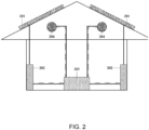
- FIG. 2 is an example of an intelligent building energy management system, not in accordance with the claimed invention, wherein the PV arrays provide both power and sensor data to the energy management system.
- two roof-mounted PV arrays 201 which may be comprised of one or more of any of a number of PV technologies, including but not limited to: crystalline silicon, thin-film inorganic technologies such as cadmium telluride, CIGS, or amorphous silicon, or OPV, or combinations of one or more types of PV technologies, send their power to their respective power conditioners (inverters) 202 .
- the example illustrates two roof-mounted PV arrays 201 . However, one or more roof-mounted PV arrays 201 may be provided.
- the power conditioners 202 convert the power from the PV arrays 201 into an appropriate format for whatever the current use for the power is; e.g. no conditioning or voltage conversion for direct current (DC) applications such as charging batteries for energy storage or DC-powered micro-grid applications, or inverters for producing alternating current (AC) for contributing to the larger grid infrastructure.
- the output parameters of voltage and current describe the power produced by the PV arrays 201, and these parameters determine what the appropriate use for the power is. As such, these parameters may be monitored and used, and in some cases are always monitored and used, as input parameters into the intelligent building energy management system 203 , which controls the power output (solid line). By comparing these output parameters to benchmark values obtained under specific conditions (i.e.
- the output parameters can be passed along to the energy management system 203 as sensor data (dashed line), and the control unit can use a calibration map to convert that data into useful information about building conditions, such as light intensity and ambient temperature.
- the energy management system 203 can then use that data to determine whether or not to activate one or more attic fans (or heat pumps), such as the two attic fans (or heat pumps) 204 illustrated in Figure 2 .
- exemplary embodiments of PV devices 201 can be configured to combine power and sensor data generation into a single unit, thereby simplifying the overall intelligent building energy management system as compared to conventional building energy management systems, such as the conventional example described in Figure 1 .
- the foregoing example describes a highly simplified building control system to illustrate the inventive features of the present invention.
- a building control system may include many more PV power and sensor generating units, additional sensor units, and additional controllable building elements.
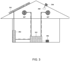
- FIG. 3 is an example of of an intelligent building energy management system, not in accordance with the claimed invention, wherein a roof-mounted PV array provides both power and sensor data to the energy management system.
- a small-area PV device also can provide sensor data and sufficient power to allow wireless transmission of the sensor data.
- the roof-mounted PV array 301 sends power to its power conditioner (inverter) 302 , which provides both power (solid line) and sensor data (dashed line) to the energy management system 303 .
- the roof-mounted small-area PV sensor device 304 provides power directly to a wireless transmitter 305 , which sends the sensor data derived from the PV sensor device output parameters to a wireless receiver 306 , which then passes the sensor information to the energy management system 303 .
- the energy management system can use the sensor data from either or both of the PV array 301 and the PV sensor device 304 to determine whether or not to turn on the attic fans (or heat pumps) 307 .
- this exemplary embodiment of a roof-mounted PV array 301 can provide both power and sensor data to an energy management system 303 , and additionally or alternatively, a small-area PV device 304 can provide sensor data and sufficient power to allow wireless transmission of the sensor data, thereby simplifying the overall intelligent building energy management system as compared to conventional building energy management systems, such as the conventional example described in Figure 1 .
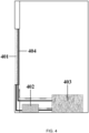
- FIG 4 is a schematic view of an example of an intelligent building energy management system, in accordance with the claimed invention wherein a BIPV device (401), in the form of, for example, a semitransparent window unit such as SolarWindow TM described above, provides both power and sensor data to the energy management system.
- the semitransparent window BIPV device 401 sends power to its power conditioner (inverter) 402 , which passes both power (solid line) and sensor data (dashed line) derived from its output parameters to the energy management system 403 , which determines whether an electrochromic window element 404 should be in its high VLT or low VLT state.
- power conditioner inverter
- this example can provide a BIPV device 401 that provides both power and sensor data to an energy management system 403 , thereby simplifying the overall intelligent building energy management system as compared to conventional building energy management systems, such as the conventional example described in Figure 1 .
- FIG. 5 is a schematic view of an example of an intelligent building energy management system wherein a BIPV device, not in accordance with the claimed invention, for example a semitransparent BIPV device, provides sensor data to the energy management system.
- a semitransparent BIPV device 501 provides power directly to a wireless transmitter 502 , which sends the sensor data derived from the PV sensor device output parameters to a wireless receiver 503 , which then passes the sensor information to the energy management system 504 .
- the energy management system 504 determines whether a dynamic window shade element 505 should be raised or lowered.
- this exemplary embodiment can provide a BIPV device 501 that provides both power and sensor data to an energy management system 503 , thereby simplifying the overall intelligent building energy management system as compared to conventional building energy management systems, such as the conventional example described in Figure 1 .
- the photovoltaic device can be a conventional roof-top photovoltaic array based upon one or more of the following photovoltaic technologies: crystalline silicon, cadmium telluride, copper-indium-gallium-selenide, copper-zinc-tin-sulfide, amorphous silicon, or organic pliotovolaties, and both the power output and sensor output can be used by the building energy management system.
- the photovoltaic device can be a small-area roof-top photovoltaic module or cell, and the power output of the device can be used to power a wireless transmitter for sending the sensor data output to the building energy management system.
- the photovoltaic device can be a semitransparent building-integrated photovoltaic module or cell based upon one of the following photovoltaic technologies: crystalline silicon, cadmium telluride, copper-indium-gallium-selenide, copper-zinc-tin-sulfide, or amorphous silicon, and both the power output and sensor output can be used by the building energy management system.
- the photovoltaic device can be a semitransparent building-integrated photovoltaic module or cell based upon one of the following photovoltaic technologies: crystalline silicon, cadmium telluride, copper-indium-gallium-selenide, copper-zinc-tin-sulfide, or amorphous silicon, and the power output can be used to power a wireless transmitter to send the sensor output data to the building energy management system.
- the photovoltaic device can be a semitransparent building-integrated photovoltaic module or cell based upon organic photovoltaic technology, and both the power output and sensor output can be used by the building energy management system.
Landscapes
- Engineering & Computer Science (AREA)
- Physics & Mathematics (AREA)
- General Physics & Mathematics (AREA)
- Thermal Sciences (AREA)
- Sustainable Development (AREA)
- Sustainable Energy (AREA)
- Life Sciences & Earth Sciences (AREA)
- Chemical & Material Sciences (AREA)
- Combustion & Propulsion (AREA)
- Mechanical Engineering (AREA)
- General Engineering & Computer Science (AREA)
- Photovoltaic Devices (AREA)
- Photometry And Measurement Of Optical Pulse Characteristics (AREA)
- Arrangements For Transmission Of Measured Signals (AREA)
- Testing Or Calibration Of Command Recording Devices (AREA)
Claims (2)
- Ein Verfahren zum Verwenden einer photovoltaischen Vorrichtung (401) als einen Sensor für eine Gebäudeenergieverwaltung, wobei das Verfahren die folgenden Schritte beinhaltet:Bereitstellen der photovoltaischen Vorrichtung (401) sowohl zum Bereitstellen von Leistung an das Gebäude als auch zum Verwenden von Ausgangsparametern der photovoltaischen Vorrichtung (401) als Sensordaten, um Informationen über aktuelle Gebäudebedingungen bereitzustellen, wobei die aktuellen Gebäudebedingungen Lichtintensität und Umgebungstemperatur umfassen, wobei die photovoltaische Vorrichtung (401) eine halbtransparente Fenstereinheit umfasst;Bestimmen der Informationen über die aktuellen Gebäudebedingungen, die Lichtintensität und Umgebungstemperatur umfassen, durch Vergleichen eines Spannungsausgangsparameters und eines Stromausgangsparameters von der photovoltaischen Vorrichtung (401) mit vorbestimmten Werten, die unter spezifischen Benchmark-Bedingungen erhalten wurden;Verwenden, durch ein Energieverwaltungssystem (403), der Informationen über die aktuellen Gebäudebedingungen als Eingangsparameter zum Bestimmen optimaler Einstellungen für ein oder mehrere Heiz-, Kühl- und dynamische energiesparende Gebäudeelemente, die wenigstens ein elektrochromes Fensterelement (404) umfassen; undBestimmen, durch das Energieverwaltungssystem (403) auf Grundlage der Informationen über die aktuellen Gebäudebedingungen, ob das elektrochrome Fensterelement (404) in einem Zustand mit hoher sichtbarer Lichtdurchlässigkeit (VLT) oder in einem Zustand mit niedriger sichtbarer Lichtdurchlässigkeit (VLT) sein sollte.
- Ein System zum Verwalten von Energie in einem Gebäude, wobei das System Folgendes beinhaltet:eine photovoltaische Vorrichtung (401);ein Energieverwaltungssystem (403), das mit der photovoltaischen Vorrichtung (401) in Verbindung steht, wobei die photovoltaische Vorrichtung (401) dazu konfiguriert ist, Leistung für das Gebäude bereitzustellen und Ausgangsparameter der photovoltaischen Vorrichtung (401) als Sensordaten zu verwenden, um Informationen über aktuelle Gebäudebedingungen bereitzustellen, wobei die photovoltaische Vorrichtung (401) eine halbtransparente Fenstereinheit umfasst,wobei das Energieverwaltungssystem dazu konfiguriert ist, einen Spannungsausgangsparameter und einen Stromausgangsparameter, die von der photovoltaischen Vorrichtung (401) empfangen werden, mit vorbestimmten Werten zu vergleichen, die unter spezifischen Benchmark-Bedingungen erhalten wurden, um Informationen über die aktuellen Gebäudebedingungen, die Lichtintensität und Umgebungstemperatur umfassen, zu bestimmen; undein oder mehrere Heiz-, Kühl- und dynamische energiesparende Bauelemente (404), die wenigstens ein elektrochromes Fensterelement (404) umfassen,wobei das Energieverwaltungssystem (403) dazu konfiguriert ist, auf Grundlage der Informationen über die aktuellen Gebäudebedingungen optimale Einstellungen für das eine oder die mehreren Heiz-, Kühl- und dynamischen energiesparenden Gebäudeelemente (404), die das elektrochrome Fensterelement (404) umfassen, zu bestimmen und auf Grundlage der Informationen über die aktuellen Gebäudebedingungen zu bestimmen, ob das elektrochrome Fensterelement (404) in einem Zustand mit hoher sichtbarer Lichtdurchlässigkeit (VLT) oder in einem Zustand mit niedriger sichtbarer Lichtdurchlässigkeit (VLT) sein sollte.
Applications Claiming Priority (2)
| Application Number | Priority Date | Filing Date | Title |
|---|---|---|---|
| US201361771612P | 2013-03-01 | 2013-03-01 | |
| PCT/US2014/019423 WO2014134451A2 (en) | 2013-03-01 | 2014-02-28 | Building intergrated photovoltaic devices as smart sensors for intelligent building energy management systems |
Publications (4)
| Publication Number | Publication Date |
|---|---|
| EP2962235A2 EP2962235A2 (de) | 2016-01-06 |
| EP2962235A4 EP2962235A4 (de) | 2017-01-04 |
| EP2962235C0 EP2962235C0 (de) | 2024-11-20 |
| EP2962235B1 true EP2962235B1 (de) | 2024-11-20 |
Family
ID=51428956
Family Applications (1)
| Application Number | Title | Priority Date | Filing Date |
|---|---|---|---|
| EP14757234.1A Active EP2962235B1 (de) | 2013-03-01 | 2014-02-28 | In ein gebäude integrierte photovoltaikvorrichtungen als intelligente sensoren für intelligente gebäudeenergieverwaltungssysteme |
Country Status (5)
| Country | Link |
|---|---|
| US (1) | US9772260B2 (de) |
| EP (1) | EP2962235B1 (de) |
| CN (1) | CN105164687B (de) |
| CA (1) | CA2941389C (de) |
| WO (1) | WO2014134451A2 (de) |
Families Citing this family (79)
| Publication number | Priority date | Publication date | Assignee | Title |
|---|---|---|---|---|
| US10747082B2 (en) | 2009-12-22 | 2020-08-18 | View, Inc. | Onboard controller for multistate windows |
| US11314139B2 (en) | 2009-12-22 | 2022-04-26 | View, Inc. | Self-contained EC IGU |
| US8213074B1 (en) | 2011-03-16 | 2012-07-03 | Soladigm, Inc. | Onboard controller for multistate windows |
| US11592723B2 (en) | 2009-12-22 | 2023-02-28 | View, Inc. | Automated commissioning of controllers in a window network |
| US10690540B2 (en) | 2015-10-06 | 2020-06-23 | View, Inc. | Multi-sensor having a light diffusing element around a periphery of a ring of photosensors |
| US10303035B2 (en) | 2009-12-22 | 2019-05-28 | View, Inc. | Self-contained EC IGU |
| US20210063836A1 (en) | 2017-04-26 | 2021-03-04 | View, Inc. | Building network |
| US20130271813A1 (en) | 2012-04-17 | 2013-10-17 | View, Inc. | Controller for optically-switchable windows |
| US9454055B2 (en) | 2011-03-16 | 2016-09-27 | View, Inc. | Multipurpose controller for multistate windows |
| US9645465B2 (en) | 2011-03-16 | 2017-05-09 | View, Inc. | Controlling transitions in optically switchable devices |
| US11054792B2 (en) | 2012-04-13 | 2021-07-06 | View, Inc. | Monitoring sites containing switchable optical devices and controllers |
| US11630367B2 (en) | 2011-03-16 | 2023-04-18 | View, Inc. | Driving thin film switchable optical devices |
| US9778532B2 (en) | 2011-03-16 | 2017-10-03 | View, Inc. | Controlling transitions in optically switchable devices |
| US11822202B2 (en) | 2011-03-16 | 2023-11-21 | View, Inc. | Controlling transitions in optically switchable devices |
| US9030725B2 (en) | 2012-04-17 | 2015-05-12 | View, Inc. | Driving thin film switchable optical devices |
| US10989977B2 (en) | 2011-03-16 | 2021-04-27 | View, Inc. | Onboard controller for multistate windows |
| US8705162B2 (en) | 2012-04-17 | 2014-04-22 | View, Inc. | Controlling transitions in optically switchable devices |
| US9412290B2 (en) | 2013-06-28 | 2016-08-09 | View, Inc. | Controlling transitions in optically switchable devices |
| US10935865B2 (en) | 2011-03-16 | 2021-03-02 | View, Inc. | Driving thin film switchable optical devices |
| WO2013059674A1 (en) | 2011-10-21 | 2013-04-25 | View, Inc. | Mitigating thermal shock in tintable windows |
| US12429742B2 (en) | 2012-03-13 | 2025-09-30 | View Operating Corporation | Methods of controlling multi-zone tintable windows |
| US11635666B2 (en) | 2012-03-13 | 2023-04-25 | View, Inc | Methods of controlling multi-zone tintable windows |
| US11950340B2 (en) | 2012-03-13 | 2024-04-02 | View, Inc. | Adjusting interior lighting based on dynamic glass tinting |
| US9638978B2 (en) | 2013-02-21 | 2017-05-02 | View, Inc. | Control method for tintable windows |
| US10048561B2 (en) | 2013-02-21 | 2018-08-14 | View, Inc. | Control method for tintable windows |
| EP2837205B1 (de) | 2012-04-13 | 2017-02-15 | View, Inc. | Anwendungen zur steuerung optisch schaltbarer vorrichtungen |
| US11300848B2 (en) | 2015-10-06 | 2022-04-12 | View, Inc. | Controllers for optically-switchable devices |
| US11674843B2 (en) | 2015-10-06 | 2023-06-13 | View, Inc. | Infrared cloud detector systems and methods |
| US10964320B2 (en) | 2012-04-13 | 2021-03-30 | View, Inc. | Controlling optically-switchable devices |
| US10503039B2 (en) | 2013-06-28 | 2019-12-10 | View, Inc. | Controlling transitions in optically switchable devices |
| US12400651B2 (en) | 2012-04-13 | 2025-08-26 | View Operating Corporation | Controlling optically-switchable devices |
| US11255120B2 (en) | 2012-05-25 | 2022-02-22 | View, Inc. | Tester and electrical connectors for insulated glass units |
| WO2014032023A1 (en) | 2012-08-23 | 2014-02-27 | View, Inc. | Photonic-powered ec devices |
| US12372846B2 (en) | 2013-02-21 | 2025-07-29 | View Operating Corporation | Control methods and systems using external 3D modeling and schedule-based computing |
| US12422725B2 (en) | 2013-02-21 | 2025-09-23 | View Operating Corporation | Control methods and systems using outside temperature as a driver for changing window tint states |
| US11966142B2 (en) | 2013-02-21 | 2024-04-23 | View, Inc. | Control methods and systems using outside temperature as a driver for changing window tint states |
| US11719990B2 (en) | 2013-02-21 | 2023-08-08 | View, Inc. | Control method for tintable windows |
| US11960190B2 (en) | 2013-02-21 | 2024-04-16 | View, Inc. | Control methods and systems using external 3D modeling and schedule-based computing |
| US9885935B2 (en) | 2013-06-28 | 2018-02-06 | View, Inc. | Controlling transitions in optically switchable devices |
| US12061404B2 (en) | 2013-06-28 | 2024-08-13 | View, Inc. | Controlling transitions in optically switchable devices |
| US12353111B2 (en) | 2013-06-28 | 2025-07-08 | View Operating Corporation | Controlling transitions in optically switchable devices |
| US10221612B2 (en) | 2014-02-04 | 2019-03-05 | View, Inc. | Infill electrochromic windows |
| US10069306B2 (en) | 2014-02-21 | 2018-09-04 | Solarlytics, Inc. | System and method for managing the power output of a photovoltaic cell |
| US11868103B2 (en) | 2014-03-05 | 2024-01-09 | View, Inc. | Site monitoring system |
| AU2015227056B2 (en) | 2014-03-05 | 2020-10-01 | View, Inc. | Monitoring sites containing switchable optical devices and controllers |
| US11150616B2 (en) | 2014-03-05 | 2021-10-19 | View, Inc. | Site monitoring system |
| US10365532B2 (en) | 2015-09-18 | 2019-07-30 | View, Inc. | Power distribution networks for electrochromic devices |
| US10859887B2 (en) | 2015-09-18 | 2020-12-08 | View, Inc. | Power distribution networks for electrochromic devices |
| US11003041B2 (en) | 2014-06-30 | 2021-05-11 | View, Inc. | Power management for electrochromic window networks |
| CN106575064B (zh) | 2014-06-30 | 2021-05-07 | 唯景公司 | 用于在功率可用性降低期间控制光学可切换窗户网络的方法和系统 |
| US10514963B2 (en) | 2014-12-08 | 2019-12-24 | View, Inc. | Multiple interacting systems at a site |
| US11740948B2 (en) | 2014-12-08 | 2023-08-29 | View, Inc. | Multiple interacting systems at a site |
| TWI746446B (zh) | 2015-07-07 | 2021-11-21 | 美商唯景公司 | 用於可著色窗戶之控制方法 |
| US11384596B2 (en) | 2015-09-18 | 2022-07-12 | View, Inc. | Trunk line window controllers |
| US12366111B2 (en) | 2015-09-18 | 2025-07-22 | View Operating Corporation | Trunk line window controllers |
| EP4290724A3 (de) | 2015-09-18 | 2024-04-03 | View, Inc. | Energieverteilungsnetze für elektrochrome vorrichtungen |
| US11255722B2 (en) | 2015-10-06 | 2022-02-22 | View, Inc. | Infrared cloud detector systems and methods |
| CN108291424B (zh) | 2015-10-29 | 2020-06-12 | 唯景公司 | 用于光学可切换装置的控制器 |
| US10763778B2 (en) * | 2015-12-09 | 2020-09-01 | Brian Patrick Janowski | Solar window construction and methods |
| US10211776B2 (en) | 2015-12-09 | 2019-02-19 | Brian Patrick Janowski | Solar window construction and methods |
| US11489483B2 (en) | 2015-12-09 | 2022-11-01 | Brian Patrick Janowski | Solar window construction and methods |
| US10138631B2 (en) * | 2016-01-25 | 2018-11-27 | Spray Tech Industries, LLC | Roofing systems and methods |
| EP4130865B1 (de) | 2016-04-29 | 2025-10-22 | View, Inc. | Kalibrierung von elektrischen parametern bei optisch schaltbaren fenstern |
| WO2017042783A1 (en) * | 2016-07-20 | 2017-03-16 | Universidad Tecnológica De Panamá | System for controlling the electrical energy for a group of buildings |
| WO2018152249A1 (en) | 2017-02-16 | 2018-08-23 | View, Inc. | Solar power dynamic glass for heating and cooling buildings |
| CN107219862B (zh) * | 2017-04-21 | 2020-12-29 | 珠海格力电器股份有限公司 | 光伏延展系统的控制方法 |
| US11747696B2 (en) | 2017-04-26 | 2023-09-05 | View, Inc. | Tandem vision window and media display |
| EP3616008A4 (de) * | 2017-04-26 | 2020-12-09 | View, Inc. | Rechenplattform für tönbares fenstersystem |
| US11493819B2 (en) | 2017-04-26 | 2022-11-08 | View, Inc. | Displays for tintable windows |
| US12147142B2 (en) | 2017-04-26 | 2024-11-19 | View, Inc. | Remote management of a facility |
| WO2019016711A1 (en) * | 2017-07-18 | 2019-01-24 | Chun Ming Lau | SYSTEM AND METHOD FOR MANAGING AND MONITORING LIFTING SYSTEMS AND CONSTRUCTION FACILITIES |
| KR20190015655A (ko) * | 2017-08-03 | 2019-02-14 | (주)비에이에너지 | 건물벽체 내장용 에너지 자립형 무선 통신 파워 컨트롤 장치 |
| JP7644501B2 (ja) | 2019-05-09 | 2025-03-12 | ビュー オペレーティング コーポレーション | 建物内の制御されたカバレッジのためのアンテナシステム |
| US11631493B2 (en) | 2020-05-27 | 2023-04-18 | View Operating Corporation | Systems and methods for managing building wellness |
| TW202206925A (zh) | 2020-03-26 | 2022-02-16 | 美商視野公司 | 多用戶端網路中之存取及傳訊 |
| CN116724404A (zh) | 2020-10-28 | 2023-09-08 | 无处不在能量公司 | 光伏智能窗户 |
| CN114297945B (zh) * | 2022-01-11 | 2025-07-29 | 重庆邮电大学 | 一种基于差分进化算法的光伏传感器优化布置方法 |
| WO2023205777A1 (en) * | 2022-04-22 | 2023-10-26 | Allen Joseph G | Intelligent building monitoring |
| US12385669B2 (en) | 2023-09-15 | 2025-08-12 | Robert L. Bullick | Water heater for heating water using various power sources and enhancing energy savings |
Citations (2)
| Publication number | Priority date | Publication date | Assignee | Title |
|---|---|---|---|---|
| US20100188057A1 (en) * | 2006-08-05 | 2010-07-29 | Min Ming Tarng | Zilinx : the 11Less Green Technology for FPIC of Smart Window |
| US20120194895A1 (en) * | 2011-01-24 | 2012-08-02 | Sage Electrochromics, Inc. | Control system for electrochromic device |
Family Cites Families (16)
| Publication number | Priority date | Publication date | Assignee | Title |
|---|---|---|---|---|
| JP3162880B2 (ja) | 1993-06-30 | 2001-05-08 | 三洋電機株式会社 | 空調制御システム |
| JP2001021202A (ja) | 1999-07-09 | 2001-01-26 | Chiyoufu Kosan Kk | スイッチ機構 |
| JP2004137852A (ja) | 2002-10-21 | 2004-05-13 | Sharp Corp | 調光装置 |
| DE202004001246U1 (de) | 2004-01-27 | 2004-04-08 | Institut für Solare Energieversorgungstechnik Verein an der Universität Kassel e.V. | Bestrahlungsstärkemessvorrichtung |
| WO2006085406A1 (ja) | 2005-02-08 | 2006-08-17 | Kazuo Miwa | 建物のエネルギー管理システム |
| JP2006300428A (ja) | 2005-04-21 | 2006-11-02 | Sekisui House Ltd | 住宅内環境ナビゲーションシステム |
| DE102006055642A1 (de) | 2006-11-22 | 2008-05-29 | Institut für Solare Energieversorgungstechnik (ISET) Verein an der Universität Kassel e.V. | Verfahren und Vorrichtung zur Ermittlung von Messwerten, die für die solare Bestrahlungsstärke am Ort eines PV-Generators charakteristisch sind |
| CN1960119B (zh) * | 2006-11-22 | 2011-05-11 | 中国科学院电工研究所 | 光伏-温差微能源与无线传感器网络节点集成自治微系统 |
| US20090014057A1 (en) * | 2007-07-13 | 2009-01-15 | Miasole | Photovoltaic modules with integrated devices |
| TWI397343B (zh) | 2008-11-21 | 2013-05-21 | Ind Tech Res Inst | 應用太陽能充電與晝光量測技術之無線傳輸模組 |
| CN201335997Y (zh) * | 2008-12-19 | 2009-10-28 | 广东工业大学 | 光伏电池阵列的组态优化控制系统 |
| US20110270446A1 (en) | 2010-05-03 | 2011-11-03 | Energy Eye, Inc. | Systems and methods for an environmental control system including a motorized vent covering |
| US20120053867A1 (en) * | 2010-08-24 | 2012-03-01 | Atonometrics, Inc. | System and methods for high-precision string-level measurement of photovoltaic array performance |
| EP2647055B1 (de) * | 2010-12-02 | 2015-08-12 | Dow Global Technologies LLC | Fotovoltaikvorrichtung zur messung von strahlung und temperatur |
| US20120271576A1 (en) * | 2011-04-22 | 2012-10-25 | Expanergy, Llc | Systems and methods for analyzing energy usage |
| US20130006435A1 (en) | 2011-07-01 | 2013-01-03 | Berrios Javier C | Solar-Powered Apparatus for Wireless Network Control of an Array of Solar Tracking Devices and Systems Based Thereon |
-
2014
- 2014-02-28 EP EP14757234.1A patent/EP2962235B1/de active Active
- 2014-02-28 CN CN201480024273.8A patent/CN105164687B/zh active Active
- 2014-02-28 CA CA2941389A patent/CA2941389C/en active Active
- 2014-02-28 WO PCT/US2014/019423 patent/WO2014134451A2/en not_active Ceased
- 2014-02-28 US US14/193,655 patent/US9772260B2/en active Active
Patent Citations (2)
| Publication number | Priority date | Publication date | Assignee | Title |
|---|---|---|---|---|
| US20100188057A1 (en) * | 2006-08-05 | 2010-07-29 | Min Ming Tarng | Zilinx : the 11Less Green Technology for FPIC of Smart Window |
| US20120194895A1 (en) * | 2011-01-24 | 2012-08-02 | Sage Electrochromics, Inc. | Control system for electrochromic device |
Also Published As
| Publication number | Publication date |
|---|---|
| EP2962235C0 (de) | 2024-11-20 |
| CN105164687B (zh) | 2021-02-05 |
| US20140330538A1 (en) | 2014-11-06 |
| WO2014134451A2 (en) | 2014-09-04 |
| CA2941389C (en) | 2023-01-24 |
| EP2962235A4 (de) | 2017-01-04 |
| EP2962235A2 (de) | 2016-01-06 |
| CN105164687A (zh) | 2015-12-16 |
| WO2014134451A3 (en) | 2015-01-29 |
| US9772260B2 (en) | 2017-09-26 |
| CA2941389A1 (en) | 2014-09-04 |
Similar Documents
| Publication | Publication Date | Title |
|---|---|---|
| EP2962235B1 (de) | In ein gebäude integrierte photovoltaikvorrichtungen als intelligente sensoren für intelligente gebäudeenergieverwaltungssysteme | |
| Ziar et al. | Photovoltatronics: intelligent PV-based devices for energy and information applications | |
| Peng et al. | Solar energy integration in buildings | |
| Sarkar et al. | A survey on development and recent trends of renewable energy generation from BIPV systems | |
| Li et al. | An analysis of a medium size grid-connected building integrated photovoltaic (BIPV) system using measured data | |
| Falih et al. | Techno-economic assessment of a hybrid connected PV solar system | |
| Shahinzadeh et al. | Design and economic study for use the photovoltaic systems for electricity supply in Isfahan Museum Park | |
| Tharakan et al. | Machine learning approach for automatic solar panel direction by using naïve bayes algorithm | |
| KR20200079360A (ko) | 건물 에너지 관리 시스템 및 이를 적용한 에너지 독립형 건물 | |
| Ishiyama | Indoor photovoltaic energy harvesting and power management for IoT devices | |
| JP2007272639A (ja) | 太陽光発電装置 | |
| Vasiliev et al. | High-transparency clear window-based agrivoltaics | |
| Barnicha et al. | Smart home energy management system monitoring and control of appliances using an arduino based network in the context of a micro-grid | |
| Maharmi et al. | Solar panel tracking control monitoring system | |
| KR20130049064A (ko) | 태양광 시스템의 설계손실 측정장치 및 방법 | |
| Qian et al. | Advancing Low-Power Self-Sustaining IoT Sensors Through CdTe PV-Driven LoRa Communication | |
| Salem | Building Integrated Photovoltaic, BIPV, System: Design and Simulation for an Educational Building | |
| Bahaj | Solar photovoltaic energy: generation in the built environment | |
| Kumar et al. | Investigation of Concentrated Semitransparent Photovoltaic System for Hot and Humid Climatic Conditions | |
| Asiri et al. | Building Integrated Photovoltaic, BIPV, System: Design and Simulation for an Educational Building | |
| Okafor et al. | Solar satellite: A green energy infrastructure for power challenged environments, a case for solar cell IV behaviour | |
| Boyekin et al. | Integrated Smart Glass and Photovoltaic Module Prototype Application Considering User Comfort Orientation | |
| Tiwari | Photovoltaic (PV) Module and Its Panel and Array | |
| Fu et al. | Design with Renewable Energy | |
| Hossain et al. | Feasibility study and design of a grid-tied low-cost solar system to replace IPS for a residential building |
Legal Events
| Date | Code | Title | Description |
|---|---|---|---|
| PUAI | Public reference made under article 153(3) epc to a published international application that has entered the european phase |
Free format text: ORIGINAL CODE: 0009012 |
|
| 17P | Request for examination filed |
Effective date: 20150930 |
|
| AK | Designated contracting states |
Kind code of ref document: A2 Designated state(s): AL AT BE BG CH CY CZ DE DK EE ES FI FR GB GR HR HU IE IS IT LI LT LU LV MC MK MT NL NO PL PT RO RS SE SI SK SM TR |
|
| AX | Request for extension of the european patent |
Extension state: BA ME |
|
| DAX | Request for extension of the european patent (deleted) | ||
| A4 | Supplementary search report drawn up and despatched |
Effective date: 20161207 |
|
| RIC1 | Information provided on ipc code assigned before grant |
Ipc: H02J 3/14 20060101ALI20161201BHEP Ipc: G06F 19/00 20110101AFI20161201BHEP |
|
| STAA | Information on the status of an ep patent application or granted ep patent |
Free format text: STATUS: REQUEST FOR EXAMINATION WAS MADE |
|
| STAA | Information on the status of an ep patent application or granted ep patent |
Free format text: STATUS: EXAMINATION IS IN PROGRESS |
|
| 17Q | First examination report despatched |
Effective date: 20171120 |
|
| RAP1 | Party data changed (applicant data changed or rights of an application transferred) |
Owner name: SOLARWINDOW TECHNOLOGIES, INC. |
|
| REG | Reference to a national code |
Ref country code: DE Ref legal event code: R079 Free format text: PREVIOUS MAIN CLASS: G06F0019000000 Ipc: H02J0003140000 Ref country code: DE Ref legal event code: R079 Ref document number: 602014091205 Country of ref document: DE Free format text: PREVIOUS MAIN CLASS: G06F0019000000 Ipc: H02J0003140000 |
|
| GRAP | Despatch of communication of intention to grant a patent |
Free format text: ORIGINAL CODE: EPIDOSNIGR1 |
|
| STAA | Information on the status of an ep patent application or granted ep patent |
Free format text: STATUS: GRANT OF PATENT IS INTENDED |
|
| RIC1 | Information provided on ipc code assigned before grant |
Ipc: H02J 3/14 20060101AFI20240515BHEP |
|
| INTG | Intention to grant announced |
Effective date: 20240617 |
|
| GRAS | Grant fee paid |
Free format text: ORIGINAL CODE: EPIDOSNIGR3 |
|
| GRAA | (expected) grant |
Free format text: ORIGINAL CODE: 0009210 |
|
| STAA | Information on the status of an ep patent application or granted ep patent |
Free format text: STATUS: THE PATENT HAS BEEN GRANTED |
|
| RAP3 | Party data changed (applicant data changed or rights of an application transferred) |
Owner name: SOLARWINDOW TECHNOLOGIES, INC. |
|
| AK | Designated contracting states |
Kind code of ref document: B1 Designated state(s): AL AT BE BG CH CY CZ DE DK EE ES FI FR GB GR HR HU IE IS IT LI LT LU LV MC MK MT NL NO PL PT RO RS SE SI SK SM TR |
|
| REG | Reference to a national code |
Ref country code: GB Ref legal event code: FG4D |
|
| REG | Reference to a national code |
Ref country code: CH Ref legal event code: EP |
|
| REG | Reference to a national code |
Ref country code: DE Ref legal event code: R096 Ref document number: 602014091205 Country of ref document: DE |
|
| REG | Reference to a national code |
Ref country code: IE Ref legal event code: FG4D |
|
| U01 | Request for unitary effect filed |
Effective date: 20241202 |
|
| U07 | Unitary effect registered |
Designated state(s): AT BE BG DE DK EE FI FR IT LT LU LV MT NL PT RO SE SI Effective date: 20241211 |
|
| U20 | Renewal fee for the european patent with unitary effect paid |
Year of fee payment: 12 Effective date: 20250108 |
|
| PG25 | Lapsed in a contracting state [announced via postgrant information from national office to epo] |
Ref country code: HR Free format text: LAPSE BECAUSE OF FAILURE TO SUBMIT A TRANSLATION OF THE DESCRIPTION OR TO PAY THE FEE WITHIN THE PRESCRIBED TIME-LIMIT Effective date: 20241120 Ref country code: IS Free format text: LAPSE BECAUSE OF FAILURE TO SUBMIT A TRANSLATION OF THE DESCRIPTION OR TO PAY THE FEE WITHIN THE PRESCRIBED TIME-LIMIT Effective date: 20250320 |
|
| PG25 | Lapsed in a contracting state [announced via postgrant information from national office to epo] |
Ref country code: ES Free format text: LAPSE BECAUSE OF FAILURE TO SUBMIT A TRANSLATION OF THE DESCRIPTION OR TO PAY THE FEE WITHIN THE PRESCRIBED TIME-LIMIT Effective date: 20241120 |
|
| PG25 | Lapsed in a contracting state [announced via postgrant information from national office to epo] |
Ref country code: NO Free format text: LAPSE BECAUSE OF FAILURE TO SUBMIT A TRANSLATION OF THE DESCRIPTION OR TO PAY THE FEE WITHIN THE PRESCRIBED TIME-LIMIT Effective date: 20250220 |
|
| PG25 | Lapsed in a contracting state [announced via postgrant information from national office to epo] |
Ref country code: GR Free format text: LAPSE BECAUSE OF FAILURE TO SUBMIT A TRANSLATION OF THE DESCRIPTION OR TO PAY THE FEE WITHIN THE PRESCRIBED TIME-LIMIT Effective date: 20250221 |
|
| PG25 | Lapsed in a contracting state [announced via postgrant information from national office to epo] |
Ref country code: PL Free format text: LAPSE BECAUSE OF FAILURE TO SUBMIT A TRANSLATION OF THE DESCRIPTION OR TO PAY THE FEE WITHIN THE PRESCRIBED TIME-LIMIT Effective date: 20241120 |
|
| PGFP | Annual fee paid to national office [announced via postgrant information from national office to epo] |
Ref country code: GB Payment date: 20250109 Year of fee payment: 12 |
|
| PG25 | Lapsed in a contracting state [announced via postgrant information from national office to epo] |
Ref country code: RS Free format text: LAPSE BECAUSE OF FAILURE TO SUBMIT A TRANSLATION OF THE DESCRIPTION OR TO PAY THE FEE WITHIN THE PRESCRIBED TIME-LIMIT Effective date: 20250220 |
|
| PG25 | Lapsed in a contracting state [announced via postgrant information from national office to epo] |
Ref country code: SM Free format text: LAPSE BECAUSE OF FAILURE TO SUBMIT A TRANSLATION OF THE DESCRIPTION OR TO PAY THE FEE WITHIN THE PRESCRIBED TIME-LIMIT Effective date: 20241120 |
|
| PG25 | Lapsed in a contracting state [announced via postgrant information from national office to epo] |
Ref country code: SK Free format text: LAPSE BECAUSE OF FAILURE TO SUBMIT A TRANSLATION OF THE DESCRIPTION OR TO PAY THE FEE WITHIN THE PRESCRIBED TIME-LIMIT Effective date: 20241120 |
|
| PG25 | Lapsed in a contracting state [announced via postgrant information from national office to epo] |
Ref country code: CZ Free format text: LAPSE BECAUSE OF FAILURE TO SUBMIT A TRANSLATION OF THE DESCRIPTION OR TO PAY THE FEE WITHIN THE PRESCRIBED TIME-LIMIT Effective date: 20241120 |
|
| PG25 | Lapsed in a contracting state [announced via postgrant information from national office to epo] |
Ref country code: MC Free format text: LAPSE BECAUSE OF FAILURE TO SUBMIT A TRANSLATION OF THE DESCRIPTION OR TO PAY THE FEE WITHIN THE PRESCRIBED TIME-LIMIT Effective date: 20241120 |
|
| PLBE | No opposition filed within time limit |
Free format text: ORIGINAL CODE: 0009261 |
|
| STAA | Information on the status of an ep patent application or granted ep patent |
Free format text: STATUS: NO OPPOSITION FILED WITHIN TIME LIMIT |
|
| REG | Reference to a national code |
Ref country code: CH Ref legal event code: PL |
|
| PG25 | Lapsed in a contracting state [announced via postgrant information from national office to epo] |
Ref country code: CH Free format text: LAPSE BECAUSE OF NON-PAYMENT OF DUE FEES Effective date: 20250228 |
|
| 26N | No opposition filed |
Effective date: 20250821 |