EP2961896B1 - Wand mit integral geformter versteifung - Google Patents
Wand mit integral geformter versteifung Download PDFInfo
- Publication number
- EP2961896B1 EP2961896B1 EP13876531.8A EP13876531A EP2961896B1 EP 2961896 B1 EP2961896 B1 EP 2961896B1 EP 13876531 A EP13876531 A EP 13876531A EP 2961896 B1 EP2961896 B1 EP 2961896B1
- Authority
- EP
- European Patent Office
- Prior art keywords
- wall
- stiffener
- side panel
- panel
- base portion
- Prior art date
- Legal status (The legal status is an assumption and is not a legal conclusion. Google has not performed a legal analysis and makes no representation as to the accuracy of the status listed.)
- Not-in-force
Links
Images


Classifications
-
- B—PERFORMING OPERATIONS; TRANSPORTING
- B66—HOISTING; LIFTING; HAULING
- B66B—ELEVATORS; ESCALATORS OR MOVING WALKWAYS
- B66B11/00—Main component parts of lifts in, or associated with, buildings or other structures
- B66B11/02—Cages, i.e. cars
- B66B11/0226—Constructional features, e.g. walls assembly, decorative panels, comfort equipment, thermal or sound insulation
-
- B—PERFORMING OPERATIONS; TRANSPORTING
- B66—HOISTING; LIFTING; HAULING
- B66B—ELEVATORS; ESCALATORS OR MOVING WALKWAYS
- B66B11/00—Main component parts of lifts in, or associated with, buildings or other structures
- B66B11/02—Cages, i.e. cars
- B66B11/0206—Car frames
-
- E—FIXED CONSTRUCTIONS
- E04—BUILDING
- E04C—STRUCTURAL ELEMENTS; BUILDING MATERIALS
- E04C2/00—Building elements of relatively thin form for the construction of parts of buildings, e.g. sheet materials, slabs, or panels
- E04C2/02—Building elements of relatively thin form for the construction of parts of buildings, e.g. sheet materials, slabs, or panels characterised by specified materials
- E04C2/08—Building elements of relatively thin form for the construction of parts of buildings, e.g. sheet materials, slabs, or panels characterised by specified materials of metal, e.g. sheet metal
-
- E—FIXED CONSTRUCTIONS
- E04—BUILDING
- E04B—GENERAL BUILDING CONSTRUCTIONS; WALLS, e.g. PARTITIONS; ROOFS; FLOORS; CEILINGS; INSULATION OR OTHER PROTECTION OF BUILDINGS
- E04B2/00—Walls, e.g. partitions, for buildings; Wall construction with regard to insulation; Connections specially adapted to walls
- E04B2/72—Non-load-bearing walls of elements of relatively thin form with respect to the thickness of the wall
Definitions
- aspects of the present invention generally relate to a wall, and more particularly relate to a wall with a stiffener integrally formed therein.
- a stiffener to reduce deflection of the wall.
- the step of attaching the stiffener to the wall can be labor intensive, and can cause damage to the wall.
- JP S62 53288 U may be useful in understanding the background of the present disclosure.
- a wall having a stiffener integrally formed therein is provided, as defined in claim 1.
- a method for integrally forming a stiffener into a wall is provided, as defined in claim 13.
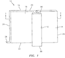
- the present disclosure describes embodiments of a wall 10 with a stiffener 12 integrally formed therein.
- the phrase "integrally formed therein" is used herein relative to the wall 10 and the stiffener 12 to describe that the wall 10 and the stiffener 12 are one unitary structure; the wall 10 and the stiffener 12 are not separate structures that are attached together.
- the wall 10 has opposing face surfaces 16, 18 and a plurality of end surfaces 20, 22, 24, 26.
- the wall 10 has a first face surface 16, a second face surface 18, a top end surface 20, a bottom end surface 22, a first side end surface 24, and a second side end surface 26.
- the wall 10 is not limited to any particular size, shape, or material.
- the wall 10 is generally rectilinearly shaped, the wall 10 has a thickness 28 extending between the opposing face surfaces 16, 18 that is equal to approximately two millimeters (2 mm), and the wall 10 is made of aluminum.
- the wall 10 may be non-rectilinearly shaped, the wall 10 may have another thickness 28 that may preferably be less than approximately 10 millimeters (10 mm), and the wall 10 may be made of another material (e.g., steel, stainless steel, metal alloys, etc.) that is capable of being formed and bent as described below.
- another material e.g., steel, stainless steel, metal alloys, etc.
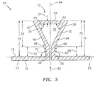
- the stiffener 12 includes a first side panel 30, a second side panel 32, an intermediate panel 34, and a cavity 36.
- the first and second side panels 30, 32 extend from the wall 10.
- the intermediate panel 34 extends between the first and second side panels 30, 32.
- the first and second side panels 30, 32 and the intermediate panel 34 at least substantially enclose a cavity 36 there between.
- the stiffener 12 has a thickness 37 that generally may be substantially equal to the thickness 28 of the wall 10.
- the first side panel 30 of the stiffener 12 includes a base portion 38 and a distal portion 40.
- the base portion 38 of the first side panel 30 extends from the wall 10.
- the distal portion 40 of the first side panel 30 is connected to the intermediate panel 34 of the stiffener 12.
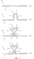
- the base portion 38 of the first side panel 30 and the wall 10 define an angle 42 that is between zero degrees (0°) and one hundred forty-five degrees (145°). In FIG. 2 , for example, the angle 42 is approximately forty-five degrees (45°). In FIGS. 3-5 , the angle 42 is approximately ninety degrees (90°).
- the distal portion 40 of the first side panel 30 and the intermediate panel 34 define an angle 44 that is between zero degrees (0°) and one hundred forty-five degrees (145°). In FIGS.
- the angle 44 is approximately forty-five degrees (45°). In FIGS. 4 and 5 , the angle 44 is approximately ninety degrees (90°).
- the base portion 38 and the distal portion 40 are shown in the drawings as being generally planar, they are not limited to planar configurations; e.g., in some embodiments, one or both of the base portion 38 and the distal portion 40 may be at least partially arcuately shaped, or otherwise shaped.
- the first side panel 30 of the stiffener 12 includes a bent portion 46 extending between the base portion 38 and the distal portion 40. The bent portion 46 may define an angle 48 that is between zero degrees (0°) and one hundred eighty degrees (180°). In FIG.
- the first side panel 30 includes a bent portion 46 that defines an angle 48 that is approximately one hundred twenty degrees (120°).
- the first side panel 30 includes a bent portion 46 that defines an angle 48 that is approximately ninety degrees (90°).
- the first side panel 30 may be characterized by a base portion height 50, a distal portion height 52, and/or a total height 54 (see FIG. 3 ).
- the base portion height 50 is the maximum heightwise distance that the base portion 38 of the first side panel 30 extends away from the wall 10.
- the distal portion height 52 is the maximum heightwise distance that the distal portion 40 of the first side panel 30 extends away from the wall 10.
- the total height 54 of the first side panel 30 is the sum of the base portion height 50 and the distal portion height 52.
- the total height 54 of the first side panel 30 may preferably be within the range of approximately ten millimeters (10 mm) to fifty millimeters (50 mm).
- the second side panel 32 of the stiffener 12 includes a base portion 56 and a distal portion 58.
- the base portion 56 of the second side panel 32 extends from the wall 10.
- the distal portion 58 of the second side panel 32 is connected to the intermediate panel 34 of the stiffener 12.
- the base portion 56 of the second side panel 32 and the wall 10 define an angle 60 that is between zero degrees (0°) and one hundred forty-five degrees (145°). In FIG. 2 , for example, the angle 60 is approximately forty-five degrees (45°). In FIGS. 3-5 , the angle 60 is approximately ninety degrees (90°).
- the distal portion 58 of the second side panel 32 and the intermediate panel 34 define an angle 62 that is between zero degrees (0°) and one hundred forty-five degrees (145°). In FIGS.
- the angle 62 is approximately forty-five degrees (45°). In FIGS. 4 and 5 , the angle 62 is approximately ninety degrees (90°).
- the base portion 56 and the distal portion 58 are shown in the drawings as being generally planar, they are not limited to planar configurations; e.g., in some embodiments, one or both of the base portion 56 and the distal portion 58 may be at least partially arcuately shaped, or otherwise shaped.
- the second side panel 32 of the stiffener 12 may include a bent portion 64 extending between the base portion 56 and the distal portion 58. The bent portion 64 may define an angle 66 that is between zero degrees (0°) and one hundred eighty degrees (180°). In FIG.
- the second side panel 32 includes a bent portion 64 that defines an angle 66 that is approximately one hundred twenty degrees (120°).
- the second side panel 32 includes a bent portion 64 that defines an angle 66 that is approximately ninety degrees (90°).
- the second side panel 32 may be characterized by a base portion height 68, a distal portion height 70, and/or a total height 72 (see FIG. 3 ).
- the base portion height 68 is the maximum heightwise distance that the base portion 56 of the second side panel 32 extends away from the wall 10.
- the distal portion height 70 is the maximum heightwise distance that the distal portion 58 of the second side panel 32 extends away from the wall 10.
- the total height 72 of the second side panel 32 is the sum of the base portion height 68 and the distal portion height 70.
- the total height 72 of the second side panel 32 may preferably be within the range of approximately ten millimeters (10 mm) to fifty millimeters (50 mm).
- the intermediate panel 34 may be generally planar, as shown for example in the embodiments of FIGS. 2 , 3 , and 5 , or the intermediate panel 34 may be at least partially arcuately shaped, or otherwise shaped.
- the intermediate panel 34 of the stiffener 12 may include a bent portion 74, 76.
- the bent portion 74, 76 may define an angle 78, 80 that is between zero degrees (0°) and one hundred forty-five degrees (145°).
- the intermediate panel 34 includes two (2) bent portions 74, 76 that define two (2) angles 78, 80, respectively.
- the angles 78, 80 both are approximately ninety degrees (90°).
- the cavity 36 is a void that is enclosed or substantially enclosed by the first and second side panels 30, 32 and the intermediate panel 34.
- the term “enclosed” is used herein relative to the cavity 36 to describe embodiments in which the first and second side panels 30, 32 are touching one another.
- the term “substantially enclosed” is used herein relative to the cavity 36 to describe embodiments in which the first and second side panels 30, 32 are in close proximity to one another.
- the cavity 36 is substantially enclosed by the first and second side panels 30, 32 and the intermediate panel 34. In the embodiments illustrated in FIGS.
- the cavity 36 is not enclosed by the first and second side panels 30, 32 and the intermediate panel 34, because the first and second side panels 30, 32 are not touching; a small gap 82 extends between the first and second side panels 30, 32.
- the cavity 36 need not have any particular size; e.g., in embodiments such as the one illustrated in FIG. 5 , the cavity 36 may be relatively small.
- the stiffener 12, or a portion of the stiffener 12, may be sized and/or shaped so that the stiffener 12 has a desired stiffness characteristic (e.g., a desired area moment of inertia). Referring to the embodiment illustrated in FIG.
- the stiffener 12 may have an area moment of inertia ( I ) relative to the axis 83 that is characterized by the following equation: I x ⁇ 2 3 h 3 t ⁇ 2 3 H 3 ⁇ h 3 t cos ⁇ ⁇ sin ⁇ cos ⁇ H ⁇ t 2 2 2 H ⁇ h ⁇ t ) t where h is the base portion height 50 of the first side panel 30 or the base portion height 68 of the second side panel 32; H is the total height 50 of the first side panel 30 or the total height 72 of the second side panel 32; t is the thickness 37 of the stiffener 12; and ⁇ is the angle 48 of the bent portion 46 of the first side panel 30 or the angle 66 of the bent portion 64 of the second side panel. Based on the equation above, the area moment of inertia ( I ) is most sensitive to changes in the dimension H.
- the first and second side panels 30, 32 and the intermediate panel 34 may be sized and shaped so that the stiffener 12 is generally symmetrical about an axis 84 (see FIGS. 2-5 ) that extends generally perpendicular to a plane defined by the wall 10.
- the first and second side panels 30, 32 and the intermediate panel 34 may be sized and shaped so that the stiffener 12 is not symmetrical.
- the first and second side panels 30, 32 may be attached to one another, for example using a mechanical fastener, welding techniques, or other acceptable means or methods.
- first and second side panels 30, 32 and the intermediate panel 34 may be sized and shaped to facilitate attachment of the first and second side panels 30, 32.
- the base portions 38, 56 of the first and second side panels 30, 32 extend generally parallel to one another, thereby facilitating attachment of the first and second side panels 30, 32.
- the stiffener 12 may extend from an end surface 20, 22, 24, 26 of the wall 10. In FIG. 1 , for example, the stiffener 12 extends from the top end surface 20 to the bottom end surface 22 of the wall 10. In FIG. 1 , a top end surface 86 of the stiffener 12 is coplanar with the top end surface 20 of the wall 10, and a bottom end surface 88 of the stiffener 12 is coplanar with the bottom end surface 22 of the wall 10. In other embodiments, the stiffener 12 may not extend from an end surface 20, 22, 24, 26 of the wall 10. In FIG. 6 , for example, the stiffener 12 does not extend from either the top end surface 20 or the bottom end surface 22 of the wall 10. In FIG. 6 , the top end surface 86 of the stiffener 12 is not coplanar with the top end surface 20 of the wall 10, and the bottom end surface 88 of the stiffener 12 is in coplanar with a bottom end surface 22 of the wall 10.
- a structure that is separate from the wall 10 and the stiffener 12 may be positioned between the first and second side panel 30, 32 of the stiffener 12.
- a decorative panel having a locating member extending there from may be positioned relative to the wall 10. The locating member of the decorative panel may extend through the gap 82 between the first and second panels 30, 32 to aid in positioning the decorative panel relative to the wall 10. In some embodiments, the locating member of the decorative panel may extend into the cavity 36 of the stiffener 12.
- the stiffener 12 can be integrally formed in the wall 10 in many different ways.
- one acceptable method for integrally forming the stiffener 12 in the wall 10 includes the steps of: (a) providing the wall 10; and (b) forming the wall 10 (e.g., using a punch press) to provide the first and second side panels 30, 32 and the intermediate panel 34 of the stiffener 12; and (c) bending the first side panel 30, the second side panel 32, and/or the intermediate panel 34 so that the first and second side panels 30, 32 and the intermediate panel 34 at least substantially encloses the cavity 36 there between.
- a punch press e.g., a punch press
- this third step is performed by biasing (e.g., using a clamp) the base portion 38 of the first side panel 30 and the base portion 56 of the second side panel 32 towards one another.
- Some methods for integrally forming the stiffener 12 in the wall 10 include the additional step of attaching the first and second side panels 30, 32 to one another.
- this optional fourth step i.e., step (d) is performed by bolting the first and second side panels 30, 32 together using a bolt 90 and a nut 92.
- the wall 10 with the stiffener 12 integrally formed therein can be used in many applications.
- the wall 10 may be particularly useful, for example, in applications that require a wall that is both stiff and lightweight.
- the wall 10 may be useful, for example, in elevator cars, or other transport cars (e.g., rail cars).
- a prior art elevator car 94 includes a door 96, a sidewall 98, a floor 100, and a ceiling 102.
- a prior art stiffener 104 is attached to the external surface 106 of the sidewall 98; the prior art stiffener 104 is not integrally formed in the sidewall 98.
- the step of attaching the prior art stiffener 104 to the sidewall 98 may be labor intensive.
- the prior art stiffener 104 may undesirably add weight to the elevator car 94.
- the prior art stiffener 104 typically may be attached to the sidewall 98 using spot welding or glue. If spot welding is used, a burn mark may be visible on the interior surface 108 of the sidewall 98. It may be necessary, therefore, to refinish or cover (e.g., with decorative paneling) the interior surface 108 of sidewall 98. If glue is used, the prior art stiffener 104 may lose contact with the sidewall 98 over time as a result of certain environmental conditions, such as high humidity or temperature. It may be necessary, therefore, to reattach the prior art stiffener 104 to the sidewall 98.
- the present wall 10 with the stiffener 12 may be just as stiff as, if not stiffer than, the sidewall 98 and the prior art stiffener 104.
- the present wall 10 with the stiffener 12 may be lighter than the sidewall 98 and the prior art stiffener 104.
- the present wall 10 with the stiffener 12 may be easier to manufacture and install than the sidewall 98 and the prior art stiffener 104; e.g., the step of attaching the prior art stiffener 104 to the sidewall 98 can be eliminated, the need to refinish or cover the interior surface of sidewall 98 can be eliminated, etc.
Landscapes
- Engineering & Computer Science (AREA)
- Civil Engineering (AREA)
- Structural Engineering (AREA)
- Architecture (AREA)
- Mechanical Engineering (AREA)
- Cage And Drive Apparatuses For Elevators (AREA)
- Finishing Walls (AREA)
Claims (14)
- Wand (10) mit einer integral geformten Versteifung (12), wobei die Versteifung (12) Folgendes umfasst:eine erste Seitenfläche (30), die sich von der Wand (10) erstreckt;eine zweite Seitenfläche (32), die sich von der Wand (10) erstreckt; undeine Zwischenfläche (34), die sich zwischen der ersten Seitenfläche (30) und der zweiten Seitenfläche (32) erstreckt;wobei die erste und die zweite Seitenfläche (30, 32) und die Zwischenfläche (34) mindestens im Wesentlichen einen Hohlraum (36) dazwischen umschließen, und die erste Seitenfläche (30) der Versteifung (12) einen Bodenabschnitt (38) und einen distalen Abschnitt (40) beinhaltet, wobei der Bodenabschnitt (38) sich von der Wand (10) erstreckt, und wobei der distale Abschnitt (40) mit der Zwischenfläche (34) der Versteifung (12) verbunden ist,dadurch gekennzeichnet, dass:
die erste Seitenfläche (30) der Versteifung (12) ferner einen gebogenen Abschnitt (46) beinhaltet, der sich zwischen dem Bodenabschnitt (38) und dem distalen Abschnitt (40) erstreckt. - Wand (10) nach Anspruch 1, wobei der Bodenabschnitt (38) der ersten Seitenfläche (30) und die Wand (10) einen Winkel (42) zwischen 0° und 145° definieren, und wobei der distale Abschnitt (40) der ersten Seitenfläche (30) und die Zwischenfläche (34) einen Winkel (44) zwischen 0° und 145° definieren, und wobei der gebogene Abschnitt (46) einen Winkel (48) zwischen 0° und 180° definiert.
- Wand (10) nach Anspruch 1 oder 2, wobei die erste Seitenfläche (30) eine Gesamthöhe zwischen 10 mm und 50 mm aufweist.
- Wand (10) nach Anspruch 1, wobei die zweite Seitenfläche (32) der Versteifung (12) einen Bodenabschnitt (56) beinhaltet, der sich von der Wand (10) erstreckt; und
wobei der Bodenabschnitt (38) der ersten Seitenfläche (30) sich allgemein parallel zu dem Bodenabschnitt (56) der zweiten Seitenfläche (32) erstreckt. - Wand (10) nach Anspruch 1, wobei die zweite Seitenfläche (32) der Versteifung (12) einen Bodenabschnitt (56) beinhaltet, der sich von der Wand (10) erstreckt; und
wobei der Bodenabschnitt (38) der ersten Seitenfläche (30) sich in unmittelbarer Nähe zu dem Bodenabschnitt (56) der zweiten Seitenfläche (32) befindet. - Wand (10) nach Anspruch 1, wobei die zweite Seitenfläche (32) der Versteifung (12) einen Bodenabschnitt (56) beinhaltet, der sich von der Wand (10) erstreckt; und
wobei der Bodenabschnitt (38) der ersten Seitenfläche (30) den Bodenabschnitt (56) der zweiten Seitenfläche (32) berührt. - Wand (10) nach einem der vorhergehenden Ansprüche, wobei die Zwischenfläche (34) einen gebogenen Abschnitt (74, 76) beinhaltet, der einen Winkel (78, 80) zwischen 0° und 145° definiert.
- Wand (10) nach einem der Ansprüche 1 bis 3, 6 oder 7, wobei die erste und die zweite Seitenfläche (30, 32) und die Zwischenfläche (34) den Hohlraum (36) dazwischen umschließen.
- Wand (10) nach Anspruch 1 bis 5 oder 7, wobei die erste und die zweite Seitenfläche (30, 32) und die Zwischenfläche (34) im Wesentlichen den Hohlraum (36) dazwischen umschließen.
- Wand (10) nach Anspruch 1 bis 5, 7 oder 9, wobei sich eine Lücke (82) zwischen der ersten und der zweiten Seitenfläche (30, 32) erstreckt.
- Wand (10) nach einem der vorhergehenden Ansprüche, wobei die Versteifung (12) allgemein symmetrisch zu einer Achse (84) ist, die sich allgemein senkrecht zu einer durch die Wand (10) definierten Ebene erstreckt.
- Aufzugkabine (94), umfassend eine Wand (10) nach einem der vorhergehenden Ansprüche.
- Verfahren zum integralen Formen einer Versteifung (12) in eine Wand (10), umfassend die folgenden Schritte:Bereitstellen der Wand (10);Formen der Wand (10), um eine erste Seitenfläche (30), eine zweite Seitenfläche (32) und eine Zwischenfläche (34) der Versteifung (12) bereitzustellen, wobei die erste Seitenfläche (30) und die zweite Seitenfläche (32) sich von der Wand (10) erstrecken, und wobei die Zwischenfläche (34) sich zwischen der ersten Seitenfläche (30) und der zweiten Seitenfläche (32) erstreckt, wobei die erste Seitenfläche (30) der Versteifung (12) einen Bodenabschnitt (38) und einen distalen Abschnitt (40) beinhaltet, wobei der Bodenabschnitt (38) sich von der Wand (10) erstreckt, und wobei der distale Abschnitt (40) mit der Zwischenfläche (34) der Versteifung (12) verbunden ist, wobei die erste Seitenfläche (30) der Versteifung (12) ferner einen gebogenen Abschnitt (46) beinhaltet, der sich zwischen dem Bodenabschnitt (38) und dem distalen Abschnitt (40) erstreckt; undBiegen mindestens einer der ersten Seitenfläche (30), der zweiten Seitenfläche (32) und der Zwischenfläche (34) der Versteifung (12), sodass die erste und die zweite Seitenfläche (30, 32) und die Zwischenfläche (34) mindestens im Wesentlichen einen Hohlraum (36) dazwischen umschließen.
- Verfahren nach Anspruch 13, ferner umfassend den Schritt des Befestigens der ersten Seitenfläche (30) an der zweiten Seitenfläche (32).
Applications Claiming Priority (1)
| Application Number | Priority Date | Filing Date | Title |
|---|---|---|---|
| PCT/US2013/027796 WO2014133484A1 (en) | 2013-02-26 | 2013-02-26 | Wall with stiffener integrally formed therein |
Publications (3)
| Publication Number | Publication Date |
|---|---|
| EP2961896A1 EP2961896A1 (de) | 2016-01-06 |
| EP2961896A4 EP2961896A4 (de) | 2016-10-26 |
| EP2961896B1 true EP2961896B1 (de) | 2018-10-31 |
Family
ID=51428613
Family Applications (1)
| Application Number | Title | Priority Date | Filing Date |
|---|---|---|---|
| EP13876531.8A Not-in-force EP2961896B1 (de) | 2013-02-26 | 2013-02-26 | Wand mit integral geformter versteifung |
Country Status (5)
| Country | Link |
|---|---|
| US (1) | US20160009527A1 (de) |
| EP (1) | EP2961896B1 (de) |
| CN (1) | CN105074099A (de) |
| ES (1) | ES2696701T3 (de) |
| WO (1) | WO2014133484A1 (de) |
Family Cites Families (9)
| Publication number | Priority date | Publication date | Assignee | Title |
|---|---|---|---|---|
| JPS4853288U (de) | 1971-10-22 | 1973-07-10 | ||
| JPS6253288U (de) * | 1985-09-20 | 1987-04-02 | ||
| JPH11350753A (ja) * | 1998-06-08 | 1999-12-21 | Sekisui Chem Co Ltd | 収納パネル |
| US8407966B2 (en) * | 2003-10-28 | 2013-04-02 | Ispan Systems Lp | Cold-formed steel joist |
| JP2006321627A (ja) * | 2005-05-20 | 2006-11-30 | Mitsubishi Electric Corp | エレベータのかご室 |
| EP1876132A1 (de) * | 2006-07-07 | 2008-01-09 | Inventio Ag | Führungsschiene für Aufzüge |
| JP2008207896A (ja) * | 2007-02-23 | 2008-09-11 | Mitsubishi Electric Corp | エレベータ装置 |
| KR101056770B1 (ko) * | 2009-03-23 | 2011-08-12 | 주식회사 미륭산업 | 롤 성형을 이용한 엘리베이터 도어 가이드레일의 제조방법 및 그 가이드레일 |
| WO2011146071A1 (en) * | 2010-05-21 | 2011-11-24 | Otis Elevator Company | Sheet metal guide rail for an elevator system |
-
2013
- 2013-02-26 EP EP13876531.8A patent/EP2961896B1/de not_active Not-in-force
- 2013-02-26 CN CN201380073832.XA patent/CN105074099A/zh active Pending
- 2013-02-26 ES ES13876531T patent/ES2696701T3/es active Active
- 2013-02-26 US US14/770,393 patent/US20160009527A1/en not_active Abandoned
- 2013-02-26 WO PCT/US2013/027796 patent/WO2014133484A1/en not_active Ceased
Non-Patent Citations (1)
| Title |
|---|
| None * |
Also Published As
| Publication number | Publication date |
|---|---|
| EP2961896A1 (de) | 2016-01-06 |
| WO2014133484A1 (en) | 2014-09-04 |
| US20160009527A1 (en) | 2016-01-14 |
| CN105074099A (zh) | 2015-11-18 |
| EP2961896A4 (de) | 2016-10-26 |
| ES2696701T3 (es) | 2019-01-17 |
Similar Documents
| Publication | Publication Date | Title |
|---|---|---|
| CA2764634C (en) | Wing panel and aircraft main wing | |
| EP3536530A1 (de) | Fahrzeugkarosseriestruktur | |
| CN104412048A (zh) | 太阳能面板支架 | |
| JP2009121479A (ja) | タワーを組立てるための方法及びシステム | |
| US10828683B2 (en) | Apparatus that manufactures closed-structure part | |
| US9315199B2 (en) | Driver's cab and railcar including driver's cab | |
| EP2682613B1 (de) | Haftflanschstruktur | |
| JP5119887B2 (ja) | 自動車のルーフ構造 | |
| US9017798B2 (en) | Press-formed product | |
| US20180016797A1 (en) | Exterior-material securing member and building exterior structure | |
| ES2413105T3 (es) | Estructura, en particular para equipos eléctricos en un vehículo ferroviario, y procedimiento para la fabricación de la estructura | |
| JP6093192B2 (ja) | 航空機の機体用パネル、航空機の翼 | |
| EP2961896B1 (de) | Wand mit integral geformter versteifung | |
| US9748891B2 (en) | Support assembly for supporting a solar panel | |
| US10773576B2 (en) | Resin back door | |
| WO2014020803A1 (ja) | クリップ | |
| JP6394538B2 (ja) | ナット取付構造 | |
| JP2015101888A (ja) | 太陽電池モジュール取付け構造 | |
| US20130076049A1 (en) | Striker for a seat | |
| JP6936606B2 (ja) | 鉄骨複合部材およびその製造方法 | |
| KR200351207Y1 (ko) | 건축용 샌드위치 패널 | |
| JP6742741B2 (ja) | 曲げ降伏型ダンパー | |
| CN218112505U (zh) | 车辆行李架安装总成和车辆 | |
| JP2016117361A (ja) | 車両前部構造 | |
| JP6273520B2 (ja) | 道路用吸音装置 |
Legal Events
| Date | Code | Title | Description |
|---|---|---|---|
| PUAI | Public reference made under article 153(3) epc to a published international application that has entered the european phase |
Free format text: ORIGINAL CODE: 0009012 |
|
| 17P | Request for examination filed |
Effective date: 20150916 |
|
| AK | Designated contracting states |
Kind code of ref document: A1 Designated state(s): AL AT BE BG CH CY CZ DE DK EE ES FI FR GB GR HR HU IE IS IT LI LT LU LV MC MK MT NL NO PL PT RO RS SE SI SK SM TR |
|
| AX | Request for extension of the european patent |
Extension state: BA ME |
|
| DAX | Request for extension of the european patent (deleted) | ||
| A4 | Supplementary search report drawn up and despatched |
Effective date: 20160928 |
|
| RIC1 | Information provided on ipc code assigned before grant |
Ipc: B66B 11/02 20060101ALI20160922BHEP Ipc: E04C 2/08 20060101ALI20160922BHEP Ipc: E04B 2/72 20060101AFI20160922BHEP |
|
| RAP1 | Party data changed (applicant data changed or rights of an application transferred) |
Owner name: OTIS ELEVATOR COMPANY |
|
| GRAP | Despatch of communication of intention to grant a patent |
Free format text: ORIGINAL CODE: EPIDOSNIGR1 |
|
| STAA | Information on the status of an ep patent application or granted ep patent |
Free format text: STATUS: GRANT OF PATENT IS INTENDED |
|
| INTG | Intention to grant announced |
Effective date: 20180514 |
|
| GRAS | Grant fee paid |
Free format text: ORIGINAL CODE: EPIDOSNIGR3 |
|
| GRAA | (expected) grant |
Free format text: ORIGINAL CODE: 0009210 |
|
| STAA | Information on the status of an ep patent application or granted ep patent |
Free format text: STATUS: THE PATENT HAS BEEN GRANTED |
|
| AK | Designated contracting states |
Kind code of ref document: B1 Designated state(s): AL AT BE BG CH CY CZ DE DK EE ES FI FR GB GR HR HU IE IS IT LI LT LU LV MC MK MT NL NO PL PT RO RS SE SI SK SM TR |
|
| REG | Reference to a national code |
Ref country code: CH Ref legal event code: EP Ref country code: GB Ref legal event code: FG4D |
|
| REG | Reference to a national code |
Ref country code: AT Ref legal event code: REF Ref document number: 1059566 Country of ref document: AT Kind code of ref document: T Effective date: 20181115 |
|
| REG | Reference to a national code |
Ref country code: DE Ref legal event code: R096 Ref document number: 602013046141 Country of ref document: DE |
|
| REG | Reference to a national code |
Ref country code: IE Ref legal event code: FG4D |
|
| REG | Reference to a national code |
Ref country code: ES Ref legal event code: FG2A Ref document number: 2696701 Country of ref document: ES Kind code of ref document: T3 Effective date: 20190117 |
|
| REG | Reference to a national code |
Ref country code: NL Ref legal event code: MP Effective date: 20181031 |
|
| REG | Reference to a national code |
Ref country code: LT Ref legal event code: MG4D |
|
| REG | Reference to a national code |
Ref country code: AT Ref legal event code: MK05 Ref document number: 1059566 Country of ref document: AT Kind code of ref document: T Effective date: 20181031 |
|
| PG25 | Lapsed in a contracting state [announced via postgrant information from national office to epo] |
Ref country code: BG Free format text: LAPSE BECAUSE OF FAILURE TO SUBMIT A TRANSLATION OF THE DESCRIPTION OR TO PAY THE FEE WITHIN THE PRESCRIBED TIME-LIMIT Effective date: 20190131 Ref country code: PL Free format text: LAPSE BECAUSE OF FAILURE TO SUBMIT A TRANSLATION OF THE DESCRIPTION OR TO PAY THE FEE WITHIN THE PRESCRIBED TIME-LIMIT Effective date: 20181031 Ref country code: FI Free format text: LAPSE BECAUSE OF FAILURE TO SUBMIT A TRANSLATION OF THE DESCRIPTION OR TO PAY THE FEE WITHIN THE PRESCRIBED TIME-LIMIT Effective date: 20181031 Ref country code: LT Free format text: LAPSE BECAUSE OF FAILURE TO SUBMIT A TRANSLATION OF THE DESCRIPTION OR TO PAY THE FEE WITHIN THE PRESCRIBED TIME-LIMIT Effective date: 20181031 Ref country code: LV Free format text: LAPSE BECAUSE OF FAILURE TO SUBMIT A TRANSLATION OF THE DESCRIPTION OR TO PAY THE FEE WITHIN THE PRESCRIBED TIME-LIMIT Effective date: 20181031 Ref country code: HR Free format text: LAPSE BECAUSE OF FAILURE TO SUBMIT A TRANSLATION OF THE DESCRIPTION OR TO PAY THE FEE WITHIN THE PRESCRIBED TIME-LIMIT Effective date: 20181031 Ref country code: AT Free format text: LAPSE BECAUSE OF FAILURE TO SUBMIT A TRANSLATION OF THE DESCRIPTION OR TO PAY THE FEE WITHIN THE PRESCRIBED TIME-LIMIT Effective date: 20181031 Ref country code: IS Free format text: LAPSE BECAUSE OF FAILURE TO SUBMIT A TRANSLATION OF THE DESCRIPTION OR TO PAY THE FEE WITHIN THE PRESCRIBED TIME-LIMIT Effective date: 20190228 Ref country code: NO Free format text: LAPSE BECAUSE OF FAILURE TO SUBMIT A TRANSLATION OF THE DESCRIPTION OR TO PAY THE FEE WITHIN THE PRESCRIBED TIME-LIMIT Effective date: 20190131 |
|
| PG25 | Lapsed in a contracting state [announced via postgrant information from national office to epo] |
Ref country code: PT Free format text: LAPSE BECAUSE OF FAILURE TO SUBMIT A TRANSLATION OF THE DESCRIPTION OR TO PAY THE FEE WITHIN THE PRESCRIBED TIME-LIMIT Effective date: 20190301 Ref country code: SE Free format text: LAPSE BECAUSE OF FAILURE TO SUBMIT A TRANSLATION OF THE DESCRIPTION OR TO PAY THE FEE WITHIN THE PRESCRIBED TIME-LIMIT Effective date: 20181031 Ref country code: NL Free format text: LAPSE BECAUSE OF FAILURE TO SUBMIT A TRANSLATION OF THE DESCRIPTION OR TO PAY THE FEE WITHIN THE PRESCRIBED TIME-LIMIT Effective date: 20181031 Ref country code: GR Free format text: LAPSE BECAUSE OF FAILURE TO SUBMIT A TRANSLATION OF THE DESCRIPTION OR TO PAY THE FEE WITHIN THE PRESCRIBED TIME-LIMIT Effective date: 20190201 Ref country code: RS Free format text: LAPSE BECAUSE OF FAILURE TO SUBMIT A TRANSLATION OF THE DESCRIPTION OR TO PAY THE FEE WITHIN THE PRESCRIBED TIME-LIMIT Effective date: 20181031 Ref country code: AL Free format text: LAPSE BECAUSE OF FAILURE TO SUBMIT A TRANSLATION OF THE DESCRIPTION OR TO PAY THE FEE WITHIN THE PRESCRIBED TIME-LIMIT Effective date: 20181031 |
|
| PG25 | Lapsed in a contracting state [announced via postgrant information from national office to epo] |
Ref country code: DK Free format text: LAPSE BECAUSE OF FAILURE TO SUBMIT A TRANSLATION OF THE DESCRIPTION OR TO PAY THE FEE WITHIN THE PRESCRIBED TIME-LIMIT Effective date: 20181031 Ref country code: IT Free format text: LAPSE BECAUSE OF FAILURE TO SUBMIT A TRANSLATION OF THE DESCRIPTION OR TO PAY THE FEE WITHIN THE PRESCRIBED TIME-LIMIT Effective date: 20181031 Ref country code: CZ Free format text: LAPSE BECAUSE OF FAILURE TO SUBMIT A TRANSLATION OF THE DESCRIPTION OR TO PAY THE FEE WITHIN THE PRESCRIBED TIME-LIMIT Effective date: 20181031 |
|
| REG | Reference to a national code |
Ref country code: DE Ref legal event code: R097 Ref document number: 602013046141 Country of ref document: DE |
|
| PG25 | Lapsed in a contracting state [announced via postgrant information from national office to epo] |
Ref country code: SK Free format text: LAPSE BECAUSE OF FAILURE TO SUBMIT A TRANSLATION OF THE DESCRIPTION OR TO PAY THE FEE WITHIN THE PRESCRIBED TIME-LIMIT Effective date: 20181031 Ref country code: SM Free format text: LAPSE BECAUSE OF FAILURE TO SUBMIT A TRANSLATION OF THE DESCRIPTION OR TO PAY THE FEE WITHIN THE PRESCRIBED TIME-LIMIT Effective date: 20181031 Ref country code: EE Free format text: LAPSE BECAUSE OF FAILURE TO SUBMIT A TRANSLATION OF THE DESCRIPTION OR TO PAY THE FEE WITHIN THE PRESCRIBED TIME-LIMIT Effective date: 20181031 Ref country code: RO Free format text: LAPSE BECAUSE OF FAILURE TO SUBMIT A TRANSLATION OF THE DESCRIPTION OR TO PAY THE FEE WITHIN THE PRESCRIBED TIME-LIMIT Effective date: 20181031 |
|
| PLBE | No opposition filed within time limit |
Free format text: ORIGINAL CODE: 0009261 |
|
| STAA | Information on the status of an ep patent application or granted ep patent |
Free format text: STATUS: NO OPPOSITION FILED WITHIN TIME LIMIT |
|
| REG | Reference to a national code |
Ref country code: CH Ref legal event code: PL |
|
| 26N | No opposition filed |
Effective date: 20190801 |
|
| GBPC | Gb: european patent ceased through non-payment of renewal fee |
Effective date: 20190226 |
|
| PG25 | Lapsed in a contracting state [announced via postgrant information from national office to epo] |
Ref country code: MC Free format text: LAPSE BECAUSE OF FAILURE TO SUBMIT A TRANSLATION OF THE DESCRIPTION OR TO PAY THE FEE WITHIN THE PRESCRIBED TIME-LIMIT Effective date: 20181031 Ref country code: SI Free format text: LAPSE BECAUSE OF FAILURE TO SUBMIT A TRANSLATION OF THE DESCRIPTION OR TO PAY THE FEE WITHIN THE PRESCRIBED TIME-LIMIT Effective date: 20181031 Ref country code: LU Free format text: LAPSE BECAUSE OF NON-PAYMENT OF DUE FEES Effective date: 20190226 |
|
| REG | Reference to a national code |
Ref country code: BE Ref legal event code: MM Effective date: 20190228 |
|
| REG | Reference to a national code |
Ref country code: IE Ref legal event code: MM4A |
|
| PG25 | Lapsed in a contracting state [announced via postgrant information from national office to epo] |
Ref country code: CH Free format text: LAPSE BECAUSE OF NON-PAYMENT OF DUE FEES Effective date: 20190228 Ref country code: LI Free format text: LAPSE BECAUSE OF NON-PAYMENT OF DUE FEES Effective date: 20190228 |
|
| PG25 | Lapsed in a contracting state [announced via postgrant information from national office to epo] |
Ref country code: GB Free format text: LAPSE BECAUSE OF NON-PAYMENT OF DUE FEES Effective date: 20190226 Ref country code: IE Free format text: LAPSE BECAUSE OF NON-PAYMENT OF DUE FEES Effective date: 20190226 |
|
| PG25 | Lapsed in a contracting state [announced via postgrant information from national office to epo] |
Ref country code: BE Free format text: LAPSE BECAUSE OF NON-PAYMENT OF DUE FEES Effective date: 20190228 |
|
| PG25 | Lapsed in a contracting state [announced via postgrant information from national office to epo] |
Ref country code: TR Free format text: LAPSE BECAUSE OF FAILURE TO SUBMIT A TRANSLATION OF THE DESCRIPTION OR TO PAY THE FEE WITHIN THE PRESCRIBED TIME-LIMIT Effective date: 20181031 |
|
| PG25 | Lapsed in a contracting state [announced via postgrant information from national office to epo] |
Ref country code: MT Free format text: LAPSE BECAUSE OF NON-PAYMENT OF DUE FEES Effective date: 20190226 |
|
| PG25 | Lapsed in a contracting state [announced via postgrant information from national office to epo] |
Ref country code: CY Free format text: LAPSE BECAUSE OF FAILURE TO SUBMIT A TRANSLATION OF THE DESCRIPTION OR TO PAY THE FEE WITHIN THE PRESCRIBED TIME-LIMIT Effective date: 20181031 |
|
| PG25 | Lapsed in a contracting state [announced via postgrant information from national office to epo] |
Ref country code: HU Free format text: LAPSE BECAUSE OF FAILURE TO SUBMIT A TRANSLATION OF THE DESCRIPTION OR TO PAY THE FEE WITHIN THE PRESCRIBED TIME-LIMIT; INVALID AB INITIO Effective date: 20130226 |
|
| PG25 | Lapsed in a contracting state [announced via postgrant information from national office to epo] |
Ref country code: MK Free format text: LAPSE BECAUSE OF FAILURE TO SUBMIT A TRANSLATION OF THE DESCRIPTION OR TO PAY THE FEE WITHIN THE PRESCRIBED TIME-LIMIT Effective date: 20181031 |
|
| PGFP | Annual fee paid to national office [announced via postgrant information from national office to epo] |
Ref country code: ES Payment date: 20240301 Year of fee payment: 12 |
|
| PGFP | Annual fee paid to national office [announced via postgrant information from national office to epo] |
Ref country code: DE Payment date: 20240123 Year of fee payment: 12 |
|
| PGFP | Annual fee paid to national office [announced via postgrant information from national office to epo] |
Ref country code: FR Payment date: 20240123 Year of fee payment: 12 |
|
| REG | Reference to a national code |
Ref country code: DE Ref legal event code: R119 Ref document number: 602013046141 Country of ref document: DE |
|
| PG25 | Lapsed in a contracting state [announced via postgrant information from national office to epo] |
Ref country code: DE Free format text: LAPSE BECAUSE OF NON-PAYMENT OF DUE FEES Effective date: 20250902 |
|
| PG25 | Lapsed in a contracting state [announced via postgrant information from national office to epo] |
Ref country code: FR Free format text: LAPSE BECAUSE OF NON-PAYMENT OF DUE FEES Effective date: 20250228 |
|
| REG | Reference to a national code |
Ref country code: ES Ref legal event code: FD2A Effective date: 20260407 |
|
| PG25 | Lapsed in a contracting state [announced via postgrant information from national office to epo] |
Ref country code: ES Free format text: LAPSE BECAUSE OF NON-PAYMENT OF DUE FEES Effective date: 20250227 |