EP2961699B1 - Process and apparatus for refining molten glass - Google Patents
Process and apparatus for refining molten glass Download PDFInfo
- Publication number
- EP2961699B1 EP2961699B1 EP14707308.4A EP14707308A EP2961699B1 EP 2961699 B1 EP2961699 B1 EP 2961699B1 EP 14707308 A EP14707308 A EP 14707308A EP 2961699 B1 EP2961699 B1 EP 2961699B1
- Authority
- EP
- European Patent Office
- Prior art keywords
- molten glass
- stream
- chamber
- refining chamber
- flow
- Prior art date
- Legal status (The legal status is an assumption and is not a legal conclusion. Google has not performed a legal analysis and makes no representation as to the accuracy of the status listed.)
- Active
Links
Images


Classifications
-
- C—CHEMISTRY; METALLURGY
- C03—GLASS; MINERAL OR SLAG WOOL
- C03B—MANUFACTURE, SHAPING, OR SUPPLEMENTARY PROCESSES
- C03B5/00—Melting in furnaces; Furnaces so far as specially adapted for glass manufacture
- C03B5/16—Special features of the melting process; Auxiliary means specially adapted for glass-melting furnaces
- C03B5/225—Refining
- C03B5/2252—Refining under reduced pressure, e.g. with vacuum refiners
-
- C—CHEMISTRY; METALLURGY
- C03—GLASS; MINERAL OR SLAG WOOL
- C03B—MANUFACTURE, SHAPING, OR SUPPLEMENTARY PROCESSES
- C03B5/00—Melting in furnaces; Furnaces so far as specially adapted for glass manufacture
- C03B5/16—Special features of the melting process; Auxiliary means specially adapted for glass-melting furnaces
- C03B5/18—Stirring devices; Homogenisation
- C03B5/187—Stirring devices; Homogenisation with moving elements
-
- C—CHEMISTRY; METALLURGY
- C03—GLASS; MINERAL OR SLAG WOOL
- C03B—MANUFACTURE, SHAPING, OR SUPPLEMENTARY PROCESSES
- C03B5/00—Melting in furnaces; Furnaces so far as specially adapted for glass manufacture
- C03B5/16—Special features of the melting process; Auxiliary means specially adapted for glass-melting furnaces
- C03B5/20—Bridges, shoes, throats, or other devices for withholding dirt, foam, or batch
-
- C—CHEMISTRY; METALLURGY
- C03—GLASS; MINERAL OR SLAG WOOL
- C03B—MANUFACTURE, SHAPING, OR SUPPLEMENTARY PROCESSES
- C03B5/00—Melting in furnaces; Furnaces so far as specially adapted for glass manufacture
- C03B5/16—Special features of the melting process; Auxiliary means specially adapted for glass-melting furnaces
- C03B5/225—Refining
- C03B5/2257—Refining by thin-layer fining
-
- C—CHEMISTRY; METALLURGY
- C03—GLASS; MINERAL OR SLAG WOOL
- C03B—MANUFACTURE, SHAPING, OR SUPPLEMENTARY PROCESSES
- C03B5/00—Melting in furnaces; Furnaces so far as specially adapted for glass manufacture
- C03B5/16—Special features of the melting process; Auxiliary means specially adapted for glass-melting furnaces
- C03B5/26—Outlets, e.g. drains, siphons; Overflows, e.g. for supplying the float tank, tweels
Definitions
- the present disclosure relates to a process and an apparatus for refining molten glass, and particularly to a process and an apparatus for continuously removing gaseous inclusions from a flowing stream of molten glass.
- Silica-based glass such as soda-lime-silica glass
- molten glass used to make such articles is conventionally prepared by melting various glass-forming materials in a furnace or tank at elevated temperature.
- the resulting molten glass typically contains gaseous inclusions, e.g., "blisters,” “bubbles,” or “seeds,” which need to be removed.
- the process of removing gaseous inclusions from molten glass is referred to as "refining,” and conventionally involves continued heating of the molten glass at high temperatures and for long periods of time to allow the gaseous inclusions to gradually rise to the surface of the molten glass and escape. This process is undesirably slow and requires high-energy input to maintain the molten glass at a suitably high temperature.
- Document US 2002/062664 A1 provides a method and an for refining a glass melting with a vacuum generated above a surface of a glass flux.
- the refinement can be improved because the glass flux is conducted upwards sequentially through several vacuum chambers, and the pressure in the successive vacuum chambers is reduced more and more relative the atmospheric pressure.
- Document JP S6237678 A also relates to a continuous refining facility for melting and refining a melt containing glass, steel, copper and the like under reduced pressure.
- the melting furnace is designed to keep the melting and refining part of the melting furnace at a high temperature for a long time in order to remove the gas content contained in the glass.
- Document JP S57149839 A describes an apparatus to feed highly defoamed and refined molten glass to a spinning section by arranging a melting section, a defoaming section and a spinning section in a line with a partition wall in-between.
- the defoaming section is formed with descending throats and weirs.
- Document US 2936549 A provides another apparatus for use in the manufacture of glass, including converter means for converting glass-forming materials into gas-containing molten glass, receiving means for receiving substantially gas-free molten glass, and conveying means operatively connected with the converter means and with the receiving means.
- the conveying means including a supporting surface adapted to support a film of molten glass flowing from the converter means to the receiving means whereby gas may easily escape from the film of flowing molten glass in order to produce a glass free of gas.
- Document AT 379793 B relates to another apparatus and method for continuously producing glass for producing glass products by introducing broken glass or frit and of refining substances in a melting furnace, melting of the starting materials and subsequent implementation of rough melting and fine melting.
- document EP 2 272 806 A1 relates to a vacuum defoaming equipment, equipment for producing a glass product and a method for producing a glass product.
- a vacuum vessel for defoaming includes a a wide portion for proving a molten glass flow path, and there the proportion of the molten flow path varies along the molten flow path, including a wider flow path section in a middle portion of the flow path.
- the general object of the present disclosure is to provide a process and an apparatus for continuously refining molten glass, which can increase the rate at which gaseous inclusions are removed from molten glass and thereby increase the efficiency of the refining process.
- a process for refining molten glass includes: (a) introducing a stream of molten glass into a controlled environment; (b) distributing the stream of molten glass over a flow surface having a length extending in a flow direction of the stream of molten glass and a width extending transverse to the flow direction of the stream of molten glass, wherein the width of the flow surface extends along the length of the flow surface from its leading edge to its trailing edge, wherein the flow surface may or may not expand in width along its entire length, such that a surface area of the stream of molten glass is increased as the stream of molten glass is distributed over the flow surface; (c) collecting the stream of molten glass from a downstream end of the flow surface to form a body of molten glass having a free surface exposed to the controlled environment; and (d) removing a stream of refined molten glass from the controlled environment at a location below the free surface of the body of molten glass, wherein the flow surface slopes
- a refining chamber for refining molten glass includes: an inlet for receiving a stream of molten glass; a distribution section for distributing the stream of molten glass over a flow surface; a reservoir section for collecting the stream of molten glass from the distribution section to form a body of molten glass; and an outlet located below a free surface of the body of molten glass for discharging a stream of refined molten glass from the refining chamber, and wherein the flow surface slopes in a generally downward direction.
- the refining chamber may further include an evacuation system for creating a sub-atmospheric pressure environment within the refining chamber.
- the process and apparatus for refining molten glass disclosed herein may be used to refine various silica-based glass compositions, including, for example, soda-lime-silica glass.
- a stream of unrefined molten glass having an undesirable amount of gaseous inclusions is supplied to an apparatus for refining molten glass, and a stream of refined molten glass having a reduced amount of gaseous inclusions is discharged from the apparatus.
- the process and apparatus of the present disclosure may be incorporated into various glass manufacturing processes and various glass furnace designs, including, but certainly not limited to, the exemplary glass manufacturing processes and glass furnace designs shown in the drawings and described hereinbelow.
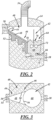
- FIG. 1 illustrates a glass furnace 10 for continuously melting, refining and homogenizing a silica-based glass composition in accordance with an exemplary embodiment of the present disclosure.
- the glass furnace 10 includes a melting chamber 12, a refining chamber 14 downstream of the melting chamber 12, and a homogenization chamber 16 downstream of the refining chamber 14.
- Glass-forming materials are supplied to the melting chamber 12, where they are heated, for example, at a temperature in the range of about 1300 degrees Celsius to about 1500 degrees Celsius, to produce a first body of molten glass 18 having a first free surface 20 exposed to an atmospheric pressure environment, e.g., an environment at ambient atmospheric pressure.
- the molten glass will contain an undesirable amount of gaseous inclusions, and thus will be "unrefined.”
- a stream of unrefined molten glass is preferably removed from the melting chamber 12 and transported to the refining chamber 14.
- Melting of the glass-forming materials in the melting chamber 12 may be performed on a batch or continuous basis, and may be accomplished using any suitable heating techniques.
- glass-forming materials are continuously supplied to the melting chamber 12 from a hopper 22 via a batch charger 24.
- the glass-forming materials may then be melted in the melting chamber 12 using electricity and/or by the combustion of fossil fuels.
- the melting chamber 12 may include a plurality of electrodes, which directly or indirectly supply heat to the glass-forming materials to produce the first body of molten glass 18.
- the melting chamber 12 may include one or more air-fueled and/or oxygen-fueled burners, which may be placed in the roof or sides of the melting chamber 12, or may be submerged within the molten glass itself.
- Unrefined molten glass may be supplied to the refining chamber 14 of the present disclosure by any suitable means.
- molten glass is supplied to the refining chamber 14 from the melting chamber 12 by way of a passageway 26 having an inlet 28 and an outlet 30.
- a pressure differential is established across the passageway 26 such that a continuous stream of molten glass can flow from the melting chamber 12, through the passageway 26, and into the refining chamber 14 without use of a pump or other mechanical device.
- the pressure differential across the passageway 26 is at least partially established by positioning the inlet 28 of the passageway 26 below the first free surface 20 of the first body of molten glass 18.
- the pressure at the inlet 28 of the passageway 26 is directly related to the hydrostatic head or height of the molten glass above the inlet 28.
- molten glass may be removed from the melting chamber 12 and supplied to the refining chamber 14 by pump or by siphon.
- a heater 32 may be located near or around a portion of the passageway 26 to heat the stream of molten glass as it flows from the melting chamber 12 to the refining chamber 14. For example, heat may be applied to the stream of molten glass to maintain or raise the temperature of the molten glass such that it exhibits a suitable viscosity for transport through the passageway 26.
- the stream of molten glass may suitably be heated to a temperature in the range of about 1450 degrees Celsius to about 1600 degrees Celsius as it flows from the melting chamber 12 to the refining chamber 14.
- the refining chamber 14 of the glass furnace 10 is an enclosed chamber in which molten glass is refined by distributing it out over a surface having an increasing surface area and exposing it to a controlled environment to expeditiously remove gaseous inclusions from the molten glass.
- controlled environment means an environment in which the temperature, pressure, humidity, and/or composition may be controlled. According to embodiments of the present disclosure, the pressure within the refining chamber 14 may be controlled to produce a sub-atmospheric environment within the refining chamber 14.
- sub-atmospheric means an environment having a pressure less than ambient atmospheric pressure, e.g., less than about 760 Torr.
- the pressure within the refining chamber 14 may be controlled to produce a sub-atmospheric environment having a pressure in the range of about 10 Torr to about 760 Torr, as this pressure range may help increase the rate at which gaseous inclusions are removed from the molten glass within the refining chamber 14.
- the pressure within the refining chamber 14 may be controlled by incorporating an evacuation system into the design of the refining chamber 14, which may include a vacuum pump and an evacuation conduit 34.
- the temperature within the refining chamber 14 also may be controlled to help increase the rate at which gaseous inclusions are removed from the molten glass. Temperature control within the refining chamber 14 may be accomplished by incorporating one or more air-fueled and/or oxygen-fueled burners into the design of the refining chamber 14.
- the refining chamber illustrated in FIGS. 1 and 2 includes an inlet 36 located in an upper portion of the refining chamber 14 for receiving a stream of unrefined molten glass, and an outlet 38 located in a lower portion of the refining chamber 14 for discharging a stream of refined molten glass therefrom.
- Molten glass is preferably held within the refining chamber 14 for a time sufficient to reduce the number of gaseous inclusions in the molten glass such that the molten glass is suitable for use in downstream forming operations.
- the residence time, or the time a volume of molten glass remains within the refining chamber 14, is controlled by controlling the rate at which molten glass enters and exits the refining chamber 14.
- the rate at which molten glass enters and exits the refining chamber 14 is controlled by adjusting the pressure within the refining chamber 14.
- the rate at which molten glass enters the refining chamber 14 may be substantially the same as the rate at which molten glass exits the refining chamber 14.
- flow control valves may be positioned at the inlet 36 and/or the outlet 38 of the refining chamber 14 to independently control of the rate at which molten glass enters and exits the refining chamber 14.
- the rate at which molten glass enters and exits the refining chamber 14 may be controlled such that it is the same or different from the rate at which the glass-forming materials are supplied to the melting chamber 12.
- the refining chamber 14 includes two sections, a distribution section 40 and a reservoir section 42, which together define a path for a stream of molten glass to flow from the inlet 36 to the outlet 38 of the refining chamber 14.
- the stream of molten glass flows through the distribution section 40, where it is distributed over a larger surface area.
- the molten glass enters the reservoir section 42, where it is collected and held for a suitable time before it is discharged from the refining chamber 14.
- the distribution section 40 has an upstream end 44, a downstream end 46, and a flow surface 48 upon which the stream of molten glass can flow from the inlet 36 of the refining chamber 14 to the reservoir section 42.
- the flow surface 48 of the distribution section 40 may be at least partially defined by walls 50, which divert from each other with respect to a flow direction of the stream of molten glass.
- the distribution section 40 also may include one or more heaters to help maintain or increase the temperature of the stream of molten glass as it flows over the flow surface 48 and into the reservoir section 42. In the embodiment shown in FIGS. 1 and 2 , a plurality of heaters 52 are positioned below the flow surface 48, which supply heat to the stream of molten glass from below.
- the stream of molten glass may suitably be heated to a temperature in the range of about 1300 degrees Celsius to about 1600 degrees Celsius as it flows over the flow surface 48.
- the flow surface 48 extends from the upstream end 44 to the downstream end 46 of the distribution section 40, and includes a leading edge 54 and a trailing edge 56.
- the flow surface 48 slopes in a generally downward direction and also increases in surface area as it extends from its leading edge 54 to its trailing edge 56.
- the flow surface 48 is configured in this way such that, when the stream of molten glass flows over the flow surface 48, it is distributed over a larger surface area, which decreases the thickness of the stream while also increasing the surface area of the stream that is exposed to the controlled environment within the refining chamber 14.
- the "thickness" of the stream of molten glass refers to the height of the stream of molten glass above the flow surface 48.
- the thickness of the stream of molten glass flowing over the flow surface 48 may be controlled, for example, by adjusting the rate at which molten glass enters the refining chamber 14, the slope angle of the flow surface 48, and the rate at which the surface area of the flow surface 48 increases.
- a suitable thickness for the stream of molten glass flowing over the flow surface 48 is in the range of about 2 cm to about 30 cm.
- the slope of the flow surface 48 may or may not be uniform along its entire length.
- the slope of the flow surface 48 may be adjusted to accommodate various flow rates, thicknesses, and viscosities of molten glass, as well as various designs and shapes of the flow surface itself.
- the flow surface 48 slopes in a generally downward direction so that gravity helps accelerate the stream of molten glass down the flow surface 48 and towards the reservoir section 42.
- the flow surface 48 may have a slope that makes an angle of greater than 0 degrees with the horizontal.
- the flow surface 48 may have a slope that makes an angle of up to and including 90 degrees with the horizontal.
- the surface area of the flow surface 48 is increased by increasing or expanding the width of the flow surface 48 as it extends from its leading edge 54 to its trailing edge 56.
- the flow surface 48 may or may not expand in width along its entire length.
- the flow surface 48 may have an expanding width section 58 and a constant width section 60.
- the flow surface 48 also may include one or more flow diverters 62 positioned within the path of the stream of molten glass to help distribute the stream of molten glass over the flow surface 48.
- the reservoir section 42 of the refining chamber 14 is located downstream of the distribution section 40 and is configured to receive a continuous stream of molten glass from the downstream end 46 of the distribution section 40.
- Molten glass is received at an open end 64 of the reservoir section 42, and is collected at a submerged end 66 of the reservoir section 42 to form a second body of molten glass 68 having a second free surface 70 exposed to the controlled environment within the refining chamber 14. Accordingly, the open end 64 of the reservoir section 42 is located above the second free surface 70, and the submerged end 66 of the reservoir section 42 is located below the second free surface 70 of the second body of molten glass 68.
- the trailing edge 56 of the flow surface 48 may be positioned above or below the second free surface 70 of the second body of molten glass 68, depending on the level or height of the second body of molten glass 68 within the reservoir section 42.
- a stirrer 72 or other suitable device may optionally be located within the reservoir section 42 to help mix or agitate the second body of molten glass 68.
- Molten glass held within the reservoir section 42 contains a reduced amount of gaseous inclusions, and is thus suitable for use in a variety downstream glass manufacturing processes.
- a stream of refined molten glass is preferably removed from the reservoir section 42 of the refining chamber 14 at a location below the second free surface 70 of the second body of molten glass 68.
- a stream of refined molten glass may be removed from the refining chamber 14 via an opening in the submerged end 66 of the reservoir section 42.
- the stream of refined molten glass may be removed from the reservoir section 42 by any suitable means, for example, by creation of a pressure differential and/or by mechanical pump.
- the refining chamber 14 is fluidly connected to the homogenization chamber 16 via a submerged passageway 74 having an inlet 76 and an outlet 78.
- a third body of molten glass 80 is held within the homogenization chamber 16 and has a third free surface 82 exposed to an atmospheric pressure environment, e.g., an environment at ambient atmospheric pressure.
- the inlet 76 of the submerged passageway 74 is located below the second free surface 70 of the second body of molten glass 68, and the outlet 78 of the submerged passageway 74 is located below the third free surface 82 of the third body of molten glass 80.
- a pressure differential is established across the submerged passageway 74 such that a continuous stream of refined molten glass flows from the reservoir section 42, through the submerged passageway 74, and into the homogenization chamber 16 without use of a pump or other mechanical device.
- the hydrostatic head or height of the second body of molten glass 68 above the inlet 76 of the submerged passageway 74 is controlled such that the pressure at the inlet 76 of the submerged passageway 74 is greater than the pressure resulting at the outlet 78 of the submerged passageway 74.
- the submerged passageway 74 also acts as a "trap,” in that the molten glass within the submerged passageway 74 creates a barrier between the refining chamber 14 and the homogenization chamber 16, which prevents air and/or other gases from entering the refining chamber 14 via the outlet 38 and potentially interfering with the controlled environment in the refining chamber 14.
- Molten glass in the homogenization chamber 16 is thoroughly mixed to chemically and thermally homogenize the glass, and to cool the glass down to a suitable temperature for downstream forming operations (e.g., less than about 1200 degrees Celsius for glass container forming operations).
Landscapes
- Chemical & Material Sciences (AREA)
- Engineering & Computer Science (AREA)
- Materials Engineering (AREA)
- Organic Chemistry (AREA)
- Glass Melting And Manufacturing (AREA)
Applications Claiming Priority (2)
| Application Number | Priority Date | Filing Date | Title |
|---|---|---|---|
| US13/782,638 US9249042B2 (en) | 2013-03-01 | 2013-03-01 | Process and apparatus for refining molten glass |
| PCT/US2014/017104 WO2014133842A1 (en) | 2013-03-01 | 2014-02-19 | Process and apparatus for refining molten glass |
Publications (2)
| Publication Number | Publication Date |
|---|---|
| EP2961699A1 EP2961699A1 (en) | 2016-01-06 |
| EP2961699B1 true EP2961699B1 (en) | 2024-04-03 |
Family
ID=50189801
Family Applications (1)
| Application Number | Title | Priority Date | Filing Date |
|---|---|---|---|
| EP14707308.4A Active EP2961699B1 (en) | 2013-03-01 | 2014-02-19 | Process and apparatus for refining molten glass |
Country Status (9)
| Country | Link |
|---|---|
| US (1) | US9249042B2 (pl) |
| EP (1) | EP2961699B1 (pl) |
| BR (1) | BR112015016639A2 (pl) |
| ES (1) | ES2978919T3 (pl) |
| HU (1) | HUE066755T2 (pl) |
| MX (1) | MX2015009809A (pl) |
| PL (1) | PL2961699T3 (pl) |
| PT (1) | PT2961699T (pl) |
| WO (1) | WO2014133842A1 (pl) |
Families Citing this family (6)
| Publication number | Priority date | Publication date | Assignee | Title |
|---|---|---|---|---|
| US10167221B2 (en) * | 2014-07-21 | 2019-01-01 | Corning Incorporated | Prefining apparatus for conditioning glasses |
| CA2974522C (en) | 2015-01-21 | 2023-03-14 | Plasma Tech Holdings, Llc | Vitrified material control system and method |
| US10815142B2 (en) | 2018-03-15 | 2020-10-27 | Owens-Brockway Glass Container Inc. | Gradient fining tank for refining foamy molten glass and a method of using the same |
| US10858277B2 (en) | 2018-03-15 | 2020-12-08 | Owens-Brockway Glass Container Inc. | Refining glass with reduced pressure |
| US11697608B2 (en) * | 2019-10-01 | 2023-07-11 | Owens-Brockway Glass Container Inc. | Selective chemical fining of small bubbles in glass |
| EP4330198B1 (en) * | 2021-04-30 | 2026-04-08 | Owens-Brockway Glass Container Inc. | High temperature and low pressure fining of submerged combustion or other glass |
Citations (1)
| Publication number | Priority date | Publication date | Assignee | Title |
|---|---|---|---|---|
| EP2272806A1 (en) * | 2008-06-02 | 2011-01-12 | Asahi Glass Company, Limited | Vacuum defoaming equipment, equipment for producing glass product, and method for producing glass product |
Family Cites Families (16)
| Publication number | Priority date | Publication date | Assignee | Title |
|---|---|---|---|---|
| US1760371A (en) * | 1926-11-19 | 1930-05-27 | Amco Inc | Apparatus for melting glass and the like |
| US2485851A (en) | 1947-02-27 | 1949-10-25 | Glass Fibers Inc | Electric melting furnace |
| US2936549A (en) | 1955-02-14 | 1960-05-17 | Mela Maschb Und Reparatur Hans | Glass making apparatus |
| ES283844A1 (es) | 1962-01-11 | 1963-03-01 | Glaverbel | Perfeccionamientos en hornos de vidriería con compartimiento de afinado del vidrio en fusión |
| JPS596827B2 (ja) | 1981-03-10 | 1984-02-14 | 日東紡績株式会社 | 再溶融式ガラス繊維製造用白金系紡糸炉 |
| AT379793B (de) | 1983-12-14 | 1986-02-25 | Harcuba Siegfried | Verfahren zum erzeugen von glas fuer die herstellung von glasprodukten sowie vorrichtung zur durchfuehrung dieses verfahrens |
| BR8402905A (pt) | 1983-06-21 | 1985-05-21 | Siegfried Harcuba | Processo e aparelho para a producao de vidro |
| JPS6237678A (ja) | 1985-08-09 | 1987-02-18 | 新日本製鐵株式会社 | 溶融物の減圧精錬装置 |
| US4780122A (en) | 1987-06-29 | 1988-10-25 | Ppg Industries, Inc. | Vacuum refining of glass or the like with enhanced foaming |
| CZ297579B6 (cs) | 1998-01-09 | 2007-02-07 | Saint-Gobain Vitrage | Zpusob a zarízení pro tavení a cerení zeskelnovatelných materiálu |
| FR2774085B3 (fr) | 1998-01-26 | 2000-02-25 | Saint Gobain Vitrage | Procede de fusion et d'affinage de matieres vitrifiables |
| JP4110663B2 (ja) | 1999-04-13 | 2008-07-02 | 旭硝子株式会社 | 溶融ガラス流の減圧脱泡方法 |
| DE10055969C1 (de) | 2000-11-11 | 2002-05-02 | Schott Glas | Verfahren und Vorrichtung zur Läuterung einer Glasschmelze |
| DE10200233C1 (de) | 2002-01-05 | 2003-04-17 | Schott Glas | Vorrichtung zum Läutern einer Glasschmelze mit einer Unterdruck-Läuterkammer |
| US8695378B2 (en) | 2008-11-26 | 2014-04-15 | Corning Incorporated | Apparatus for making glass and methods |
| JP5904204B2 (ja) | 2011-07-15 | 2016-04-13 | 日東紡績株式会社 | ガラス溶融装置、ガラス繊維製造装置及びガラス繊維製造方法 |
-
2013
- 2013-03-01 US US13/782,638 patent/US9249042B2/en active Active
-
2014
- 2014-02-19 PT PT147073084T patent/PT2961699T/pt unknown
- 2014-02-19 ES ES14707308T patent/ES2978919T3/es active Active
- 2014-02-19 PL PL14707308.4T patent/PL2961699T3/pl unknown
- 2014-02-19 BR BR112015016639A patent/BR112015016639A2/pt not_active IP Right Cessation
- 2014-02-19 WO PCT/US2014/017104 patent/WO2014133842A1/en not_active Ceased
- 2014-02-19 HU HUE14707308A patent/HUE066755T2/hu unknown
- 2014-02-19 EP EP14707308.4A patent/EP2961699B1/en active Active
- 2014-02-19 MX MX2015009809A patent/MX2015009809A/es unknown
Patent Citations (1)
| Publication number | Priority date | Publication date | Assignee | Title |
|---|---|---|---|---|
| EP2272806A1 (en) * | 2008-06-02 | 2011-01-12 | Asahi Glass Company, Limited | Vacuum defoaming equipment, equipment for producing glass product, and method for producing glass product |
Also Published As
| Publication number | Publication date |
|---|---|
| MX2015009809A (es) | 2015-10-29 |
| HUE066755T2 (hu) | 2024-09-28 |
| PL2961699T3 (pl) | 2024-06-17 |
| EP2961699A1 (en) | 2016-01-06 |
| WO2014133842A1 (en) | 2014-09-04 |
| ES2978919T3 (es) | 2024-09-23 |
| US9249042B2 (en) | 2016-02-02 |
| PT2961699T (pt) | 2024-05-24 |
| BR112015016639A2 (pt) | 2017-07-11 |
| US20140245793A1 (en) | 2014-09-04 |
Similar Documents
| Publication | Publication Date | Title |
|---|---|---|
| EP2961699B1 (en) | Process and apparatus for refining molten glass | |
| JP6821603B2 (ja) | 溶融ガラスを調整するための装置及び方法 | |
| DK168209B1 (da) | Fremgangsmåde og apparat til vakuumraffinering af glas eller lignende materiale med forøget skumning | |
| EP3152169B1 (en) | Process and apparatus for refining molten glass | |
| US10858277B2 (en) | Refining glass with reduced pressure | |
| CN110799462A (zh) | 用于减少玻璃熔体表面上的气泡寿命的方法 | |
| WO2013011837A1 (ja) | ガラス溶融装置、ガラス繊維製造装置及びガラス繊維製造方法 | |
| CN110357399B (zh) | 用于生产玻璃产品的方法及适于此的装置 | |
| US10167221B2 (en) | Prefining apparatus for conditioning glasses | |
| KR102514358B1 (ko) | 유리 제조 시스템을 재조정하는 방법 | |
| EP3765413B1 (en) | Vacuum refining of molten glass | |
| US9932258B1 (en) | Apparatus and process for making glass and glass gobs | |
| US12486190B2 (en) | Fining molten material using reduced pressure | |
| EP4051645B1 (en) | Glass fining using an objective and molten metal | |
| TWI530464B (zh) | Molten glass guide |
Legal Events
| Date | Code | Title | Description |
|---|---|---|---|
| PUAI | Public reference made under article 153(3) epc to a published international application that has entered the european phase |
Free format text: ORIGINAL CODE: 0009012 |
|
| 17P | Request for examination filed |
Effective date: 20150903 |
|
| AK | Designated contracting states |
Kind code of ref document: A1 Designated state(s): AL AT BE BG CH CY CZ DE DK EE ES FI FR GB GR HR HU IE IS IT LI LT LU LV MC MK MT NL NO PL PT RO RS SE SI SK SM TR |
|
| AX | Request for extension of the european patent |
Extension state: BA ME |
|
| DAX | Request for extension of the european patent (deleted) | ||
| STAA | Information on the status of an ep patent application or granted ep patent |
Free format text: STATUS: EXAMINATION IS IN PROGRESS |
|
| 17Q | First examination report despatched |
Effective date: 20190528 |
|
| RIC1 | Information provided on ipc code assigned before grant |
Ipc: C03B 5/26 20060101ALI20221018BHEP Ipc: C03B 5/20 20060101ALI20221018BHEP Ipc: C03B 5/18 20060101ALI20221018BHEP Ipc: C03B 5/187 20060101ALI20221018BHEP Ipc: C03B 5/225 20060101AFI20221018BHEP |
|
| GRAP | Despatch of communication of intention to grant a patent |
Free format text: ORIGINAL CODE: EPIDOSNIGR1 |
|
| STAA | Information on the status of an ep patent application or granted ep patent |
Free format text: STATUS: GRANT OF PATENT IS INTENDED |
|
| INTG | Intention to grant announced |
Effective date: 20230530 |
|
| RIN1 | Information on inventor provided before grant (corrected) |
Inventor name: WANG, ZHONGMING Inventor name: HOWSE, TERENCE K.G. |
|
| P01 | Opt-out of the competence of the unified patent court (upc) registered |
Effective date: 20230630 |
|
| GRAJ | Information related to disapproval of communication of intention to grant by the applicant or resumption of examination proceedings by the epo deleted |
Free format text: ORIGINAL CODE: EPIDOSDIGR1 |
|
| STAA | Information on the status of an ep patent application or granted ep patent |
Free format text: STATUS: EXAMINATION IS IN PROGRESS |
|
| GRAP | Despatch of communication of intention to grant a patent |
Free format text: ORIGINAL CODE: EPIDOSNIGR1 |
|
| STAA | Information on the status of an ep patent application or granted ep patent |
Free format text: STATUS: GRANT OF PATENT IS INTENDED |
|
| INTC | Intention to grant announced (deleted) | ||
| INTG | Intention to grant announced |
Effective date: 20231030 |
|
| GRAS | Grant fee paid |
Free format text: ORIGINAL CODE: EPIDOSNIGR3 |
|
| GRAA | (expected) grant |
Free format text: ORIGINAL CODE: 0009210 |
|
| STAA | Information on the status of an ep patent application or granted ep patent |
Free format text: STATUS: THE PATENT HAS BEEN GRANTED |
|
| AK | Designated contracting states |
Kind code of ref document: B1 Designated state(s): AL AT BE BG CH CY CZ DE DK EE ES FI FR GB GR HR HU IE IS IT LI LT LU LV MC MK MT NL NO PL PT RO RS SE SI SK SM TR |
|
| REG | Reference to a national code |
Ref country code: GB Ref legal event code: FG4D |
|
| REG | Reference to a national code |
Ref country code: CH Ref legal event code: EP |
|
| REG | Reference to a national code |
Ref country code: IE Ref legal event code: FG4D |
|
| REG | Reference to a national code |
Ref country code: DE Ref legal event code: R096 Ref document number: 602014089827 Country of ref document: DE |
|
| REG | Reference to a national code |
Ref country code: NL Ref legal event code: FP |
|
| REG | Reference to a national code |
Ref country code: PT Ref legal event code: SC4A Ref document number: 2961699 Country of ref document: PT Date of ref document: 20240524 Kind code of ref document: T Free format text: AVAILABILITY OF NATIONAL TRANSLATION Effective date: 20240521 |
|
| REG | Reference to a national code |
Ref country code: EE Ref legal event code: FG4A Ref document number: E024256 Country of ref document: EE Effective date: 20240502 |
|
| REG | Reference to a national code |
Ref country code: LT Ref legal event code: MG9D |
|
| REG | Reference to a national code |
Ref country code: AT Ref legal event code: MK05 Ref document number: 1672167 Country of ref document: AT Kind code of ref document: T Effective date: 20240403 |
|
| REG | Reference to a national code |
Ref country code: ES Ref legal event code: FG2A Ref document number: 2978919 Country of ref document: ES Kind code of ref document: T3 Effective date: 20240923 |
|
| REG | Reference to a national code |
Ref country code: HU Ref legal event code: AG4A Ref document number: E066755 Country of ref document: HU |
|
| PG25 | Lapsed in a contracting state [announced via postgrant information from national office to epo] |
Ref country code: IS Free format text: LAPSE BECAUSE OF FAILURE TO SUBMIT A TRANSLATION OF THE DESCRIPTION OR TO PAY THE FEE WITHIN THE PRESCRIBED TIME-LIMIT Effective date: 20240803 |
|
| PG25 | Lapsed in a contracting state [announced via postgrant information from national office to epo] |
Ref country code: BG Free format text: LAPSE BECAUSE OF FAILURE TO SUBMIT A TRANSLATION OF THE DESCRIPTION OR TO PAY THE FEE WITHIN THE PRESCRIBED TIME-LIMIT Effective date: 20240403 |
|
| PG25 | Lapsed in a contracting state [announced via postgrant information from national office to epo] |
Ref country code: HR Free format text: LAPSE BECAUSE OF FAILURE TO SUBMIT A TRANSLATION OF THE DESCRIPTION OR TO PAY THE FEE WITHIN THE PRESCRIBED TIME-LIMIT Effective date: 20240403 Ref country code: FI Free format text: LAPSE BECAUSE OF FAILURE TO SUBMIT A TRANSLATION OF THE DESCRIPTION OR TO PAY THE FEE WITHIN THE PRESCRIBED TIME-LIMIT Effective date: 20240403 |
|
| PG25 | Lapsed in a contracting state [announced via postgrant information from national office to epo] |
Ref country code: GR Free format text: LAPSE BECAUSE OF FAILURE TO SUBMIT A TRANSLATION OF THE DESCRIPTION OR TO PAY THE FEE WITHIN THE PRESCRIBED TIME-LIMIT Effective date: 20240704 |
|
| PG25 | Lapsed in a contracting state [announced via postgrant information from national office to epo] |
Ref country code: AT Free format text: LAPSE BECAUSE OF FAILURE TO SUBMIT A TRANSLATION OF THE DESCRIPTION OR TO PAY THE FEE WITHIN THE PRESCRIBED TIME-LIMIT Effective date: 20240403 |
|
| PG25 | Lapsed in a contracting state [announced via postgrant information from national office to epo] |
Ref country code: LV Free format text: LAPSE BECAUSE OF FAILURE TO SUBMIT A TRANSLATION OF THE DESCRIPTION OR TO PAY THE FEE WITHIN THE PRESCRIBED TIME-LIMIT Effective date: 20240403 |
|
| PG25 | Lapsed in a contracting state [announced via postgrant information from national office to epo] |
Ref country code: NO Free format text: LAPSE BECAUSE OF FAILURE TO SUBMIT A TRANSLATION OF THE DESCRIPTION OR TO PAY THE FEE WITHIN THE PRESCRIBED TIME-LIMIT Effective date: 20240703 Ref country code: LV Free format text: LAPSE BECAUSE OF FAILURE TO SUBMIT A TRANSLATION OF THE DESCRIPTION OR TO PAY THE FEE WITHIN THE PRESCRIBED TIME-LIMIT Effective date: 20240403 Ref country code: IS Free format text: LAPSE BECAUSE OF FAILURE TO SUBMIT A TRANSLATION OF THE DESCRIPTION OR TO PAY THE FEE WITHIN THE PRESCRIBED TIME-LIMIT Effective date: 20240803 Ref country code: HR Free format text: LAPSE BECAUSE OF FAILURE TO SUBMIT A TRANSLATION OF THE DESCRIPTION OR TO PAY THE FEE WITHIN THE PRESCRIBED TIME-LIMIT Effective date: 20240403 Ref country code: GR Free format text: LAPSE BECAUSE OF FAILURE TO SUBMIT A TRANSLATION OF THE DESCRIPTION OR TO PAY THE FEE WITHIN THE PRESCRIBED TIME-LIMIT Effective date: 20240704 Ref country code: FI Free format text: LAPSE BECAUSE OF FAILURE TO SUBMIT A TRANSLATION OF THE DESCRIPTION OR TO PAY THE FEE WITHIN THE PRESCRIBED TIME-LIMIT Effective date: 20240403 Ref country code: BG Free format text: LAPSE BECAUSE OF FAILURE TO SUBMIT A TRANSLATION OF THE DESCRIPTION OR TO PAY THE FEE WITHIN THE PRESCRIBED TIME-LIMIT Effective date: 20240403 Ref country code: AT Free format text: LAPSE BECAUSE OF FAILURE TO SUBMIT A TRANSLATION OF THE DESCRIPTION OR TO PAY THE FEE WITHIN THE PRESCRIBED TIME-LIMIT Effective date: 20240403 Ref country code: RS Free format text: LAPSE BECAUSE OF FAILURE TO SUBMIT A TRANSLATION OF THE DESCRIPTION OR TO PAY THE FEE WITHIN THE PRESCRIBED TIME-LIMIT Effective date: 20240703 |
|
| REG | Reference to a national code |
Ref country code: DE Ref legal event code: R097 Ref document number: 602014089827 Country of ref document: DE |
|
| PG25 | Lapsed in a contracting state [announced via postgrant information from national office to epo] |
Ref country code: DK Free format text: LAPSE BECAUSE OF FAILURE TO SUBMIT A TRANSLATION OF THE DESCRIPTION OR TO PAY THE FEE WITHIN THE PRESCRIBED TIME-LIMIT Effective date: 20240403 |
|
| PG25 | Lapsed in a contracting state [announced via postgrant information from national office to epo] |
Ref country code: RO Free format text: LAPSE BECAUSE OF FAILURE TO SUBMIT A TRANSLATION OF THE DESCRIPTION OR TO PAY THE FEE WITHIN THE PRESCRIBED TIME-LIMIT Effective date: 20240403 Ref country code: SK Free format text: LAPSE BECAUSE OF FAILURE TO SUBMIT A TRANSLATION OF THE DESCRIPTION OR TO PAY THE FEE WITHIN THE PRESCRIBED TIME-LIMIT Effective date: 20240403 |
|
| PG25 | Lapsed in a contracting state [announced via postgrant information from national office to epo] |
Ref country code: SM Free format text: LAPSE BECAUSE OF FAILURE TO SUBMIT A TRANSLATION OF THE DESCRIPTION OR TO PAY THE FEE WITHIN THE PRESCRIBED TIME-LIMIT Effective date: 20240403 |
|
| PG25 | Lapsed in a contracting state [announced via postgrant information from national office to epo] |
Ref country code: SM Free format text: LAPSE BECAUSE OF FAILURE TO SUBMIT A TRANSLATION OF THE DESCRIPTION OR TO PAY THE FEE WITHIN THE PRESCRIBED TIME-LIMIT Effective date: 20240403 Ref country code: SK Free format text: LAPSE BECAUSE OF FAILURE TO SUBMIT A TRANSLATION OF THE DESCRIPTION OR TO PAY THE FEE WITHIN THE PRESCRIBED TIME-LIMIT Effective date: 20240403 Ref country code: RO Free format text: LAPSE BECAUSE OF FAILURE TO SUBMIT A TRANSLATION OF THE DESCRIPTION OR TO PAY THE FEE WITHIN THE PRESCRIBED TIME-LIMIT Effective date: 20240403 Ref country code: DK Free format text: LAPSE BECAUSE OF FAILURE TO SUBMIT A TRANSLATION OF THE DESCRIPTION OR TO PAY THE FEE WITHIN THE PRESCRIBED TIME-LIMIT Effective date: 20240403 |
|
| PLBE | No opposition filed within time limit |
Free format text: ORIGINAL CODE: 0009261 |
|
| STAA | Information on the status of an ep patent application or granted ep patent |
Free format text: STATUS: NO OPPOSITION FILED WITHIN TIME LIMIT |
|
| 26N | No opposition filed |
Effective date: 20250106 |
|
| PG25 | Lapsed in a contracting state [announced via postgrant information from national office to epo] |
Ref country code: SI Free format text: LAPSE BECAUSE OF FAILURE TO SUBMIT A TRANSLATION OF THE DESCRIPTION OR TO PAY THE FEE WITHIN THE PRESCRIBED TIME-LIMIT Effective date: 20240403 |
|
| PG25 | Lapsed in a contracting state [announced via postgrant information from national office to epo] |
Ref country code: SE Free format text: LAPSE BECAUSE OF FAILURE TO SUBMIT A TRANSLATION OF THE DESCRIPTION OR TO PAY THE FEE WITHIN THE PRESCRIBED TIME-LIMIT Effective date: 20240403 |
|
| PG25 | Lapsed in a contracting state [announced via postgrant information from national office to epo] |
Ref country code: MC Free format text: LAPSE BECAUSE OF FAILURE TO SUBMIT A TRANSLATION OF THE DESCRIPTION OR TO PAY THE FEE WITHIN THE PRESCRIBED TIME-LIMIT Effective date: 20240403 |
|
| PG25 | Lapsed in a contracting state [announced via postgrant information from national office to epo] |
Ref country code: LU Free format text: LAPSE BECAUSE OF NON-PAYMENT OF DUE FEES Effective date: 20250219 |
|
| REG | Reference to a national code |
Ref country code: BE Ref legal event code: MM Effective date: 20250228 |
|
| PG25 | Lapsed in a contracting state [announced via postgrant information from national office to epo] |
Ref country code: IT Free format text: LAPSE BECAUSE OF NON-PAYMENT OF DUE FEES Effective date: 20250219 |
|
| PG25 | Lapsed in a contracting state [announced via postgrant information from national office to epo] |
Ref country code: BE Free format text: LAPSE BECAUSE OF NON-PAYMENT OF DUE FEES Effective date: 20250228 |
|
| PG25 | Lapsed in a contracting state [announced via postgrant information from national office to epo] |
Ref country code: IE Free format text: LAPSE BECAUSE OF NON-PAYMENT OF DUE FEES Effective date: 20250219 |
|
| REG | Reference to a national code |
Ref country code: CH Ref legal event code: U11 Free format text: ST27 STATUS EVENT CODE: U-0-0-U10-U11 (AS PROVIDED BY THE NATIONAL OFFICE) Effective date: 20260301 |
|
| PGFP | Annual fee paid to national office [announced via postgrant information from national office to epo] |
Ref country code: NL Payment date: 20260226 Year of fee payment: 13 |
|
| PGFP | Annual fee paid to national office [announced via postgrant information from national office to epo] |
Ref country code: HU Payment date: 20260209 Year of fee payment: 13 |
|
| PGFP | Annual fee paid to national office [announced via postgrant information from national office to epo] |
Ref country code: GB Payment date: 20260227 Year of fee payment: 13 |
|
| PGFP | Annual fee paid to national office [announced via postgrant information from national office to epo] |
Ref country code: ES Payment date: 20260302 Year of fee payment: 13 |
|
| PGFP | Annual fee paid to national office [announced via postgrant information from national office to epo] |
Ref country code: DE Payment date: 20260227 Year of fee payment: 13 |
|
| PG25 | Lapsed in a contracting state [announced via postgrant information from national office to epo] |
Ref country code: IT Free format text: LAPSE BECAUSE OF NON-PAYMENT OF DUE FEES Effective date: 20250219 |
|
| PGFP | Annual fee paid to national office [announced via postgrant information from national office to epo] |
Ref country code: IT Payment date: 20260219 Year of fee payment: 13 |
|
| PGRI | Patent reinstated in contracting state [announced from national office to epo] |
Ref country code: IT Effective date: 20250630 |
|
| PGFP | Annual fee paid to national office [announced via postgrant information from national office to epo] |
Ref country code: FR Payment date: 20260225 Year of fee payment: 13 |
|
| PGFP | Annual fee paid to national office [announced via postgrant information from national office to epo] |
Ref country code: TR Payment date: 20260206 Year of fee payment: 13 |
|
| PGFP | Annual fee paid to national office [announced via postgrant information from national office to epo] |
Ref country code: PT Payment date: 20260204 Year of fee payment: 13 Ref country code: CH Payment date: 20260301 Year of fee payment: 13 Ref country code: CZ Payment date: 20260205 Year of fee payment: 13 |
|
| PGFP | Annual fee paid to national office [announced via postgrant information from national office to epo] |
Ref country code: PL Payment date: 20260201 Year of fee payment: 13 |
|
| PGFP | Annual fee paid to national office [announced via postgrant information from national office to epo] |
Ref country code: EE Payment date: 20260210 Year of fee payment: 13 |