EP2960919A1 - Dispositif de commutation electrique - Google Patents
Dispositif de commutation electrique Download PDFInfo
- Publication number
- EP2960919A1 EP2960919A1 EP15174085.9A EP15174085A EP2960919A1 EP 2960919 A1 EP2960919 A1 EP 2960919A1 EP 15174085 A EP15174085 A EP 15174085A EP 2960919 A1 EP2960919 A1 EP 2960919A1
- Authority
- EP
- European Patent Office
- Prior art keywords
- switching device
- housing
- actuator
- clip
- switching
- Prior art date
- Legal status (The legal status is an assumption and is not a legal conclusion. Google has not performed a legal analysis and makes no representation as to the accuracy of the status listed.)
- Granted
Links
Images


Classifications
-
- H—ELECTRICITY
- H01—ELECTRIC ELEMENTS
- H01H—ELECTRIC SWITCHES; RELAYS; SELECTORS; EMERGENCY PROTECTIVE DEVICES
- H01H3/00—Mechanisms for operating contacts
- H01H3/02—Operating parts, i.e. for operating driving mechanism by a mechanical force external to the switch
- H01H3/16—Operating parts, i.e. for operating driving mechanism by a mechanical force external to the switch adapted for actuation at a limit or other predetermined position in the path of a body, the relative movement of switch and body being primarily for a purpose other than the actuation of the switch, e.g. for a door switch, a limit switch, a floor-levelling switch of a lift
-
- H—ELECTRICITY
- H01—ELECTRIC ELEMENTS
- H01H—ELECTRIC SWITCHES; RELAYS; SELECTORS; EMERGENCY PROTECTIVE DEVICES
- H01H13/00—Switches having rectilinearly-movable operating part or parts adapted for pushing or pulling in one direction only, e.g. push-button switch
- H01H13/50—Switches having rectilinearly-movable operating part or parts adapted for pushing or pulling in one direction only, e.g. push-button switch having a single operating member
- H01H13/503—Stacked switches
-
- H—ELECTRICITY
- H01—ELECTRIC ELEMENTS
- H01H—ELECTRIC SWITCHES; RELAYS; SELECTORS; EMERGENCY PROTECTIVE DEVICES
- H01H13/00—Switches having rectilinearly-movable operating part or parts adapted for pushing or pulling in one direction only, e.g. push-button switch
- H01H13/02—Details
- H01H13/12—Movable parts; Contacts mounted thereon
- H01H13/14—Operating parts, e.g. push-button
- H01H13/18—Operating parts, e.g. push-button adapted for actuation at a limit or other predetermined position in the path of a body, the relative movement of switch and body being primarily for a purpose other than the actuation of the switch, e.g. door switch, limit switch, floor-levelling switch of a lift
-
- H—ELECTRICITY
- H01—ELECTRIC ELEMENTS
- H01H—ELECTRIC SWITCHES; RELAYS; SELECTORS; EMERGENCY PROTECTIVE DEVICES
- H01H11/00—Apparatus or processes specially adapted for the manufacture of electric switches
- H01H11/0006—Apparatus or processes specially adapted for the manufacture of electric switches for converting electric switches
- H01H11/0018—Apparatus or processes specially adapted for the manufacture of electric switches for converting electric switches for allowing different operating parts
- H01H2011/0025—Apparatus or processes specially adapted for the manufacture of electric switches for converting electric switches for allowing different operating parts with provisions for allowing different orientation of the operating part, e.g. turning knob can be mounted in different positions
-
- H—ELECTRICITY
- H01—ELECTRIC ELEMENTS
- H01H—ELECTRIC SWITCHES; RELAYS; SELECTORS; EMERGENCY PROTECTIVE DEVICES
- H01H3/00—Mechanisms for operating contacts
- H01H3/02—Operating parts, i.e. for operating driving mechanism by a mechanical force external to the switch
- H01H3/16—Operating parts, i.e. for operating driving mechanism by a mechanical force external to the switch adapted for actuation at a limit or other predetermined position in the path of a body, the relative movement of switch and body being primarily for a purpose other than the actuation of the switch, e.g. for a door switch, a limit switch, a floor-levelling switch of a lift
- H01H3/161—Operating parts, i.e. for operating driving mechanism by a mechanical force external to the switch adapted for actuation at a limit or other predetermined position in the path of a body, the relative movement of switch and body being primarily for a purpose other than the actuation of the switch, e.g. for a door switch, a limit switch, a floor-levelling switch of a lift for actuation by moving a closing member, e.g. door, cover or lid
Definitions
- the invention relates to an electrical switching device according to claim 1.
- the electrical switching device can be designed in particular as a position switch, limit switches, micro-switches or other limit switches.
- Such electrical switching devices are used, for example, for the monitoring of mechanical variables, for example for the shutdown of electrical machines when a security door is opened.
- a position sensor with an alignment mechanism known.
- a position switch with a rotating head emerges.
- the invention has for its object to provide an improved in particular in terms of functionality and manufacturability electrical switching device.
- the invention has the advantage that mechanically robust components are proposed, which are inexpensive to produce and offer a favorable, ergonomic handling for the user.
- the electrical switching contacts are arranged in the housing of the electrical switching device and can be contacted there via cables.
- an actuator present which can be secured against rotation on the housing of the switching device in different rotational angle positions, which has the advantage that the switching device can be used very universally and a simple adaptation to different detection tasks by adjusting the rotational angle position is possible.
- a clasp is proposed which engages over both parts, namely by being slidable over at least a portion of the actuator and at least a portion of the housing of the switching device.
- the sliding movement which can be guided by corresponding guide grooves, is easy to carry out by the user. It can be attached to the housing of the switching device in a simple and ergonomic manner, the actuator.
- the clasp is slidable only along a translational straight line over at least part of the actuator and at least part of the housing of the switching device.
- the degrees of freedom of movement are limited when using the clip for attaching the actuator to the housing of the switching device. This simplifies the attachment of the clip for the user.
- the actuator can be mounted in different rotational angular positions on the housing of the switching device.
- the actuator may be provided that the actuator is only in different discrete rotational angular positions, e.g. at certain angular intervals, can be fastened.
- discrete rotational angular positions e.g. at certain angular intervals, can be fastened.
- discrete rotational angle positions e.g. 4, 6, 8 or more discrete rotational angle positions may be provided.
- the clip has at least one Axialfixierstoff by which the actuator is fixed in the direction of its longitudinal axis relative to the housing of the switching device.
- the actuator has a circumferential groove into which a web of the clip is immersed to form the at least one Axialfixierstoff.
- the clip has at least one Rotationsfixierstoff, by means of which the actuator is fixed against rotation with respect to its longitudinal axis relative to the housing of the switching device.
- This has the advantage that the clip acts as a further function for preventing rotation of the actuator.
- a multifunctional clasp can be specified which combines a multiplicity of advantageous functions in one component.
- the clasp may be formed in particular both with the at least one Axialfixierstoff and with the at least one Rotationsfixierstoff.
- the at least one Axialfixierstoff has a different outer shape than the at least one Rotationsfixierstoff.
- the Axialfixierstoff and the Rotationsfixierstoff may be formed as different parts of the clasp. It is possible to arrange the at least one Axialfixierstoff with spatial distance to the at least one Rotationsfixierstoff on the clip. This has the advantage that not the same part of the clasp must serve as Axialfixierstoff and Rotationsfixierstoff. The burden on the individual fixative is thereby reduced.
- the Axialfixierstoff can be designed independently of the Rotationsfixierstoff and designed to be constructive, since both fixing means are decoupled from each other.
- the clip with its Rotationsfixierstoffn and the separate Axialfixierstoffn each in direct mechanical contact with the actuator.
- the clip has a trained in the form of a nub or tooth Rotationsfixierstoff, which is adapted to engage in a recess of a plurality of arranged on the circumference of the actuator recesses.
- the recesses may e.g. be formed in the form of blind holes, notches, grooves or other depressions.
- the clip is slidable in a non-parallel to the longitudinal axis of the actuator direction, in particular in a direction perpendicular thereto, over at least a portion of the actuator and at least a portion of the housing of the switching device.
- the clip has at least one securing means which is adapted to cooperate with at least one receiving means designed as a counterpart on the housing of the switching device for securing the clip on the housing of the switching device.
- the securing means may be formed, for example, as a latching fastening means be, which engages after pushing the clip on the housing of the switching device at the local receiving means.
- the latching connection can for example be designed so that it can only be solved by tools.
- the at least one securing means in cooperation with the at least one receiving means allows a limited displaceability of the clip relative to the housing of the switching device to an end stop, in which the clip is still secured to the housing of the switching device.
- the actuator of the switching device can be removed and / or rotated about its longitudinal axis when the at least one securing means is displaced towards the end stop.
- This has the advantage that the clasp does not have to be completely removed from the housing, but the displacement path within the secured area can be used to remove the actuator from the indexing device or attach it to it, e.g. to replace an actuator, or to select a desired other rotational angular position of the actuator.
- the actuating opening in the housing of the switching device, in which the actuator is used is designed as a cylindrical or conical opening.
- a purely cylindrical or conical opening has the advantage that it is easy to manufacture.
- the function of the rotation can be moved into the clip, so that the housing of the switching device can be made simpler and in particular can be made easier.
- the tooling costs and the manufacturing process can be optimized.
- the clip has at least one mounting means for mounting the switching device to another object.
- the clasp can be used as a mounting means e.g. Having openings for the passage of screws. As a result, the functionality of the clasp is further expanded.
- the housing of the switching device has a hinged on a main housing part rotatably mounted lid, which is hinged and closable, wherein in the unfolded state, the arranged in the housing electrical contacts for connecting electrical cables are accessible.
- the lid covers at least a portion of the clip in the closed state.
- the lid can at the same time provide a mechanical safeguard for the clip in order to prevent its displacement relative to the housing of the switching device or at least to reduce the displacement.
- the cover can be prevented by the cover a displacement of the clip to a position in which the actuator can be removed from the switching device and / or about its longitudinal axis is rotatable.
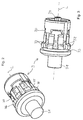
- FIG. 1 shows an electrical switching device 1, which has a housing 2, 20, an actuator 3 and a clasp 4 as separate components to be assembled.
- the clip 4 is additionally shown left above the housing 2, 20 again separately.
- the housing 2, 20 has a main housing part 2 and a lid 20 attached thereto via a hinge 23.
- the lid 20 is pivotable about the hinge 23 and may be of the in FIG. 1 shown opened position can be folded down and thus closes the main body part 2 upwards from.
- electrical switching contacts 26 which may be formed as an opener, closer or changeover, as needed.
- electrical switching contacts 26 There may be a plurality of electrical switching contacts that are the same or different in terms of the switching function.
- one or more of the switching contacts may be designed as a creeping switch or as a snap-action switch.
- the switching contacts can also be designed as overlapping openers, which only open when an associated closer is closed.
- the housing 2, 20 has an actuating opening 24 on a front side, via which the switching contacts 26 can be actuated mechanically from the outside of the housing 2, 20.
- a Jardineinwoomaschinetechnik 25 is present on the opposite rear side of the housing 2, 20.
- electrical connection cables can be led from the outside to the switching contacts 26 in order to connect them electrically.
- the actuator 3 has a substantially cylindrical body 30. Within the body 30 is located along a longitudinal axis L of the actuator 3 longitudinally displaceable actuating plunger 31, which on the in FIG. 1 unrecognizable rear side of the actuator 3 projects therefrom and thus the switch contacts 26 can operate.
- the actuator 3 is to be inserted into the actuating opening 24 and attached thereto.
- the clip 4 is provided in order to fix the actuator 3 on the housing 2, 20 in the actuating opening 24, the clip 4 is provided.
- the clasp 4 can from above, ie in a direction substantially perpendicular to the longitudinal axis L direction A (as in FIG. 5 shown) and thereby covers a part of the actuator 3 and a part of the main body part. 2
- the clasp 4 is, as mentioned above, shown separately in the upper left and in addition in an on the main body part 2 at least partially deferred position. In this position, the actuator 3 can be inserted into the actuating opening 24, in a desired rotational angular position. Then, when the clasp 4 is further displaced downwards, it fixes the actuator 3 at the same time in the axial direction, i. with respect to a displacement in the direction of the longitudinal axis L, and with respect to a rotation about the longitudinal axis L.
- the additional means required for this purpose are described in more detail with reference to the following figures.
- the clip 4 as mounting means 41 has two openings. Through these screws can be guided.
- the complete unit, ie the switching device 1 can be fastened to another object via screws guided by the mounting means 41.
- the cover 20 has a region 21 projecting in the direction of the clasp 4.
- the lid 20 overlaps in the closed state with the clip 4 and fixes them relative to the housing 2, 20.
- locking means 22 are arranged, with which the lid 20 can be connected to the main housing part 2 latching and the housing 2, 20 can be securely closed in this way.
- FIGS. 2 and 3 show further details of the actuator. It can be seen that the actuator 31 has a through actuating tappet 31, 34. When the actuator 3 is fixed to the housing 2, 20, the part 31 of the actuating tappet points outwards. The part 34 points into the interior of the housing 2, 20 and acted upon appropriate actuation of the outer part 31, the electrical switching contacts 26 mechanically.
- the actuator 3 has a circumferential groove 33 on the outer circumference of its body 30. This serves in conjunction with a protruding wall region of the clasp 4 designed as an axial fixing means 40 for axially fixing the actuator 3 to the housing 2, 20.
- the actuator 3 likewise has recesses 35 arranged on the outer circumference of the body 30 between protruding projections 32. These act together with the clip 4 as explained below.
- FIGS. 4 and 5 Is recognizable in the FIGS. 4 and 5 the clasp 4 in different views, wherein once again the protruding wall portion which forms the Axialfixierstoff 40, can be seen.
- longitudinal grooves 46 are arranged in the clip, which engage over the projections 32 of the actuator when sliding the clip.
- the clasp 4 On an inner side of the projecting wall portion, the clasp 4 as Rotationsfixierstoff 43 a protruding tooth or a knob. This Rotationsfixierstoff 43 engages in one of the recesses 35 in order to effect a rotation of the actuator 3.
- the clasp 4 may have corrugations 44 on two opposite outer sides where the clasp is gripped by hand.
- this has in the direction of the main housing part 2 projecting securing means 45, which may be formed, for example, as snap-fastening means.
- the securing means 45 cooperate with receiving means arranged on the housing 2, 20, more precisely on the main housing part 2, which after the attachment of the clasp 4 on the main housing part 2 continue to allow a certain limited displaceability of the clasp 4, but a complete Prevent removal of the clip 4 from the main body part 2.
- the clasp 4 can be in their in FIG. 1 shown position upwards relative to the main housing part 2 are moved.
- the actuator 3 can be inserted into or removed from the actuating opening 24, or a different rotational angle position of the actuator 3 can be selected.
- the clip 4 is moved downward and secured over the protruding portion 21 of the lid 20.
- the clasp 4 is secured in position by screws which are guided by the mounting means 41.
- FIG. 7 shows a section through the switching device 1 in a plane through the Rotationsfixierstoff 43. It can be seen how the Rotationsfixierstoff 43 engages in one of the recesses 35 between two adjacent projections 32 and thus secures the actuator 3 against rotation.
- FIG. 6 shows a section through the switching device 1 in a plane through the Axialfixierstoff 40. It can be seen that the Axialfixierstoff 40 surrounds the actuator 3 over an angular range of about 180 °. In this case, the circumferential groove 33 bears against the axial fixing means 40.
Applications Claiming Priority (1)
| Application Number | Priority Date | Filing Date | Title |
|---|---|---|---|
| DE102014109072.1A DE102014109072B4 (de) | 2014-06-27 | 2014-06-27 | Elektrische Schalteinrichtung |
Publications (2)
| Publication Number | Publication Date |
|---|---|
| EP2960919A1 true EP2960919A1 (fr) | 2015-12-30 |
| EP2960919B1 EP2960919B1 (fr) | 2017-03-15 |
Family
ID=53510652
Family Applications (1)
| Application Number | Title | Priority Date | Filing Date |
|---|---|---|---|
| EP15174085.9A Active EP2960919B1 (fr) | 2014-06-27 | 2015-06-26 | Dispositif de commutation electrique |
Country Status (4)
| Country | Link |
|---|---|
| US (1) | US9646777B2 (fr) |
| EP (1) | EP2960919B1 (fr) |
| DE (1) | DE102014109072B4 (fr) |
| DK (1) | DK2960919T3 (fr) |
Citations (6)
| Publication number | Priority date | Publication date | Assignee | Title |
|---|---|---|---|---|
| EP0017124A1 (fr) * | 1979-03-28 | 1980-10-15 | Square D Starkstrom GmbH | Appareil électrique, notamment appareil d'installation |
| US5230422A (en) * | 1990-11-05 | 1993-07-27 | Allen-Bradley Company, Inc. | Operator/cartridge assembly |
| US6376785B1 (en) * | 1999-09-27 | 2002-04-23 | Rockwell Automation Technologies, Inc. | Removable latch assembly for an electrical switch |
| EP1131832B1 (fr) | 1998-11-18 | 2002-10-02 | Crouzet Automatismes | Detecteur de position avec mecanisme d'orientation |
| EP1302956B1 (fr) | 2001-10-15 | 2007-11-21 | Schneider Electric Industries SAS | Interrupteur, notamment de position, à tête orientable |
| US20120103769A1 (en) * | 2010-10-29 | 2012-05-03 | Rockwell Automation Technologies, Inc. | Electrical switch latch assembly |
Family Cites Families (1)
| Publication number | Priority date | Publication date | Assignee | Title |
|---|---|---|---|---|
| US6198058B1 (en) * | 1999-09-27 | 2001-03-06 | Rockwell Technologies, Llc | Switch contact mechanism |
-
2014
- 2014-06-27 DE DE102014109072.1A patent/DE102014109072B4/de not_active Expired - Fee Related
-
2015
- 2015-06-26 US US14/752,168 patent/US9646777B2/en active Active
- 2015-06-26 DK DK15174085.9T patent/DK2960919T3/en active
- 2015-06-26 EP EP15174085.9A patent/EP2960919B1/fr active Active
Patent Citations (6)
| Publication number | Priority date | Publication date | Assignee | Title |
|---|---|---|---|---|
| EP0017124A1 (fr) * | 1979-03-28 | 1980-10-15 | Square D Starkstrom GmbH | Appareil électrique, notamment appareil d'installation |
| US5230422A (en) * | 1990-11-05 | 1993-07-27 | Allen-Bradley Company, Inc. | Operator/cartridge assembly |
| EP1131832B1 (fr) | 1998-11-18 | 2002-10-02 | Crouzet Automatismes | Detecteur de position avec mecanisme d'orientation |
| US6376785B1 (en) * | 1999-09-27 | 2002-04-23 | Rockwell Automation Technologies, Inc. | Removable latch assembly for an electrical switch |
| EP1302956B1 (fr) | 2001-10-15 | 2007-11-21 | Schneider Electric Industries SAS | Interrupteur, notamment de position, à tête orientable |
| US20120103769A1 (en) * | 2010-10-29 | 2012-05-03 | Rockwell Automation Technologies, Inc. | Electrical switch latch assembly |
Also Published As
| Publication number | Publication date |
|---|---|
| EP2960919B1 (fr) | 2017-03-15 |
| US20150380177A1 (en) | 2015-12-31 |
| DE102014109072A1 (de) | 2015-12-31 |
| US9646777B2 (en) | 2017-05-09 |
| DE102014109072B4 (de) | 2016-06-30 |
| DK2960919T3 (en) | 2017-05-15 |
Similar Documents
| Publication | Publication Date | Title |
|---|---|---|
| DE102012111397B4 (de) | Motorhaubenverriegelungsvorrichtung mit Zwei-Stufen-Führung für ein Fahrzeug | |
| EP1501453B2 (fr) | Implant reglable en hauteur destine a etre insere entre des vertebres et outil de manipulation | |
| DE602006000338T2 (de) | Antriebsvorrichtung eines elektischen Schaltgerätes mit Schaltsperre | |
| DE102011076568A1 (de) | Steckverbinder | |
| DE102009008281A1 (de) | Vorrichtung mit einer Kameraeinheit zur Bilderfassung des Außenbereiches eines Kraftfahrzeugs | |
| EP2584577B1 (fr) | Agencement de sécurisation du commutateur à plusieurs pôles pour systèmes de barre collectrice | |
| EP3914468B1 (fr) | Dispositif de raccordement de charge pour un véhicule | |
| EP2634785B1 (fr) | Dispositif de commutation | |
| EP1643060A2 (fr) | Construction de charnière et dispositif de protection avec construction de charnière | |
| DE102015220484A1 (de) | Tankdeckel | |
| DE102013103451A1 (de) | Türkontaktschalter, insbesondere für Schaltschränke | |
| DE102011002135B4 (de) | Steckerelement mit zweiter Kontaktsicherung | |
| EP1681206A1 (fr) | Dispositif incluant un manchon d'étanchéité pour le passage entre des parties de véhicules, mobiles l'une par rapport à l'autre | |
| DE102020211128A1 (de) | Endoskop mit einer funktion zur verhinderung einer kettenverklemmung | |
| DE3421930A1 (de) | Endoskop | |
| DE102008053137A1 (de) | Hebelverbindung | |
| EP2960919B1 (fr) | Dispositif de commutation electrique | |
| DE102019200066A1 (de) | Lukenanordnung für ein Freizeitfahrzeug | |
| DE602004006486T2 (de) | Verriegelungsmechanismus und ein damit ausgerüstetes Schiebedach | |
| DE102014108728A1 (de) | Verschlusseinrichtung und Steckvorrichtung mit einer derartigen Verschlusseinrichtung | |
| EP2067152B1 (fr) | Sectionneur de sécurité à coupure en charge avec dispositif de verrouillage | |
| DE102015118903A1 (de) | Kabelführungselement | |
| EP3626914A1 (fr) | Dispositif de rappel destiné à la manipulation d'une ferrure et procédé de transfert d'un dispositif de rappel entre une première position de manipulation et une seconde position de manipulation | |
| DE102013113588A1 (de) | Haubenschloss mit einer dualen Entsperrfunktion | |
| EP2632006B1 (fr) | Passage de câble entre deux éléments se déplaçant l'un par rapport à l'autre, notamment entre un battant de porte et un cadre de porte ainsi que serrure ou barre anti-panique avec un tel passage de câble |
Legal Events
| Date | Code | Title | Description |
|---|---|---|---|
| PUAI | Public reference made under article 153(3) epc to a published international application that has entered the european phase |
Free format text: ORIGINAL CODE: 0009012 |
|
| AK | Designated contracting states |
Kind code of ref document: A1 Designated state(s): AL AT BE BG CH CY CZ DE DK EE ES FI FR GB GR HR HU IE IS IT LI LT LU LV MC MK MT NL NO PL PT RO RS SE SI SK SM TR |
|
| AX | Request for extension of the european patent |
Extension state: BA ME |
|
| 17P | Request for examination filed |
Effective date: 20160113 |
|
| RBV | Designated contracting states (corrected) |
Designated state(s): AL AT BE BG CH CY CZ DE DK EE ES FI FR GB GR HR HU IE IS IT LI LT LU LV MC MK MT NL NO PL PT RO RS SE SI SK SM TR |
|
| RIC1 | Information provided on ipc code assigned before grant |
Ipc: H01H 13/50 20060101AFI20160718BHEP Ipc: H01H 13/18 20060101ALI20160718BHEP Ipc: H01H 3/16 20060101ALI20160718BHEP |
|
| GRAP | Despatch of communication of intention to grant a patent |
Free format text: ORIGINAL CODE: EPIDOSNIGR1 |
|
| INTG | Intention to grant announced |
Effective date: 20160929 |
|
| GRAS | Grant fee paid |
Free format text: ORIGINAL CODE: EPIDOSNIGR3 |
|
| GRAA | (expected) grant |
Free format text: ORIGINAL CODE: 0009210 |
|
| AK | Designated contracting states |
Kind code of ref document: B1 Designated state(s): AL AT BE BG CH CY CZ DE DK EE ES FI FR GB GR HR HU IE IS IT LI LT LU LV MC MK MT NL NO PL PT RO RS SE SI SK SM TR |
|
| REG | Reference to a national code |
Ref country code: CH Ref legal event code: EP Ref country code: GB Ref legal event code: FG4D Free format text: NOT ENGLISH |
|
| REG | Reference to a national code |
Ref country code: IE Ref legal event code: FG4D Free format text: LANGUAGE OF EP DOCUMENT: GERMAN |
|
| REG | Reference to a national code |
Ref country code: AT Ref legal event code: REF Ref document number: 876333 Country of ref document: AT Kind code of ref document: T Effective date: 20170415 |
|
| REG | Reference to a national code |
Ref country code: FR Ref legal event code: PLFP Year of fee payment: 3 |
|
| REG | Reference to a national code |
Ref country code: DE Ref legal event code: R096 Ref document number: 502015000710 Country of ref document: DE |
|
| REG | Reference to a national code |
Ref country code: DK Ref legal event code: T3 Effective date: 20170511 |
|
| REG | Reference to a national code |
Ref country code: NL Ref legal event code: FP |
|
| REG | Reference to a national code |
Ref country code: SE Ref legal event code: TRGR |
|
| REG | Reference to a national code |
Ref country code: LT Ref legal event code: MG4D |
|
| PG25 | Lapsed in a contracting state [announced via postgrant information from national office to epo] |
Ref country code: FI Free format text: LAPSE BECAUSE OF FAILURE TO SUBMIT A TRANSLATION OF THE DESCRIPTION OR TO PAY THE FEE WITHIN THE PRESCRIBED TIME-LIMIT Effective date: 20170315 Ref country code: LT Free format text: LAPSE BECAUSE OF FAILURE TO SUBMIT A TRANSLATION OF THE DESCRIPTION OR TO PAY THE FEE WITHIN THE PRESCRIBED TIME-LIMIT Effective date: 20170315 Ref country code: HR Free format text: LAPSE BECAUSE OF FAILURE TO SUBMIT A TRANSLATION OF THE DESCRIPTION OR TO PAY THE FEE WITHIN THE PRESCRIBED TIME-LIMIT Effective date: 20170315 Ref country code: NO Free format text: LAPSE BECAUSE OF FAILURE TO SUBMIT A TRANSLATION OF THE DESCRIPTION OR TO PAY THE FEE WITHIN THE PRESCRIBED TIME-LIMIT Effective date: 20170615 Ref country code: GR Free format text: LAPSE BECAUSE OF FAILURE TO SUBMIT A TRANSLATION OF THE DESCRIPTION OR TO PAY THE FEE WITHIN THE PRESCRIBED TIME-LIMIT Effective date: 20170616 |
|
| PG25 | Lapsed in a contracting state [announced via postgrant information from national office to epo] |
Ref country code: RS Free format text: LAPSE BECAUSE OF FAILURE TO SUBMIT A TRANSLATION OF THE DESCRIPTION OR TO PAY THE FEE WITHIN THE PRESCRIBED TIME-LIMIT Effective date: 20170315 Ref country code: LV Free format text: LAPSE BECAUSE OF FAILURE TO SUBMIT A TRANSLATION OF THE DESCRIPTION OR TO PAY THE FEE WITHIN THE PRESCRIBED TIME-LIMIT Effective date: 20170315 Ref country code: BG Free format text: LAPSE BECAUSE OF FAILURE TO SUBMIT A TRANSLATION OF THE DESCRIPTION OR TO PAY THE FEE WITHIN THE PRESCRIBED TIME-LIMIT Effective date: 20170615 |
|
| PG25 | Lapsed in a contracting state [announced via postgrant information from national office to epo] |
Ref country code: RO Free format text: LAPSE BECAUSE OF FAILURE TO SUBMIT A TRANSLATION OF THE DESCRIPTION OR TO PAY THE FEE WITHIN THE PRESCRIBED TIME-LIMIT Effective date: 20170315 Ref country code: SK Free format text: LAPSE BECAUSE OF FAILURE TO SUBMIT A TRANSLATION OF THE DESCRIPTION OR TO PAY THE FEE WITHIN THE PRESCRIBED TIME-LIMIT Effective date: 20170315 Ref country code: CZ Free format text: LAPSE BECAUSE OF FAILURE TO SUBMIT A TRANSLATION OF THE DESCRIPTION OR TO PAY THE FEE WITHIN THE PRESCRIBED TIME-LIMIT Effective date: 20170315 Ref country code: EE Free format text: LAPSE BECAUSE OF FAILURE TO SUBMIT A TRANSLATION OF THE DESCRIPTION OR TO PAY THE FEE WITHIN THE PRESCRIBED TIME-LIMIT Effective date: 20170315 Ref country code: ES Free format text: LAPSE BECAUSE OF FAILURE TO SUBMIT A TRANSLATION OF THE DESCRIPTION OR TO PAY THE FEE WITHIN THE PRESCRIBED TIME-LIMIT Effective date: 20170315 |
|
| PG25 | Lapsed in a contracting state [announced via postgrant information from national office to epo] |
Ref country code: PL Free format text: LAPSE BECAUSE OF FAILURE TO SUBMIT A TRANSLATION OF THE DESCRIPTION OR TO PAY THE FEE WITHIN THE PRESCRIBED TIME-LIMIT Effective date: 20170315 Ref country code: IS Free format text: LAPSE BECAUSE OF FAILURE TO SUBMIT A TRANSLATION OF THE DESCRIPTION OR TO PAY THE FEE WITHIN THE PRESCRIBED TIME-LIMIT Effective date: 20170715 Ref country code: PT Free format text: LAPSE BECAUSE OF FAILURE TO SUBMIT A TRANSLATION OF THE DESCRIPTION OR TO PAY THE FEE WITHIN THE PRESCRIBED TIME-LIMIT Effective date: 20170717 Ref country code: SM Free format text: LAPSE BECAUSE OF FAILURE TO SUBMIT A TRANSLATION OF THE DESCRIPTION OR TO PAY THE FEE WITHIN THE PRESCRIBED TIME-LIMIT Effective date: 20170315 |
|
| REG | Reference to a national code |
Ref country code: DE Ref legal event code: R097 Ref document number: 502015000710 Country of ref document: DE |
|
| PLBE | No opposition filed within time limit |
Free format text: ORIGINAL CODE: 0009261 |
|
| STAA | Information on the status of an ep patent application or granted ep patent |
Free format text: STATUS: NO OPPOSITION FILED WITHIN TIME LIMIT |
|
| PG25 | Lapsed in a contracting state [announced via postgrant information from national office to epo] |
Ref country code: MC Free format text: LAPSE BECAUSE OF FAILURE TO SUBMIT A TRANSLATION OF THE DESCRIPTION OR TO PAY THE FEE WITHIN THE PRESCRIBED TIME-LIMIT Effective date: 20170315 |
|
| 26N | No opposition filed |
Effective date: 20171218 |
|
| PG25 | Lapsed in a contracting state [announced via postgrant information from national office to epo] |
Ref country code: SI Free format text: LAPSE BECAUSE OF FAILURE TO SUBMIT A TRANSLATION OF THE DESCRIPTION OR TO PAY THE FEE WITHIN THE PRESCRIBED TIME-LIMIT Effective date: 20170315 |
|
| REG | Reference to a national code |
Ref country code: IE Ref legal event code: MM4A |
|
| PG25 | Lapsed in a contracting state [announced via postgrant information from national office to epo] |
Ref country code: LU Free format text: LAPSE BECAUSE OF NON-PAYMENT OF DUE FEES Effective date: 20170626 Ref country code: IE Free format text: LAPSE BECAUSE OF NON-PAYMENT OF DUE FEES Effective date: 20170626 |
|
| REG | Reference to a national code |
Ref country code: BE Ref legal event code: MM Effective date: 20170630 |
|
| REG | Reference to a national code |
Ref country code: FR Ref legal event code: PLFP Year of fee payment: 4 |
|
| PG25 | Lapsed in a contracting state [announced via postgrant information from national office to epo] |
Ref country code: BE Free format text: LAPSE BECAUSE OF NON-PAYMENT OF DUE FEES Effective date: 20170630 |
|
| PG25 | Lapsed in a contracting state [announced via postgrant information from national office to epo] |
Ref country code: MT Free format text: LAPSE BECAUSE OF FAILURE TO SUBMIT A TRANSLATION OF THE DESCRIPTION OR TO PAY THE FEE WITHIN THE PRESCRIBED TIME-LIMIT Effective date: 20170315 |
|
| REG | Reference to a national code |
Ref country code: CH Ref legal event code: PL |
|
| PG25 | Lapsed in a contracting state [announced via postgrant information from national office to epo] |
Ref country code: LI Free format text: LAPSE BECAUSE OF NON-PAYMENT OF DUE FEES Effective date: 20180630 Ref country code: CH Free format text: LAPSE BECAUSE OF NON-PAYMENT OF DUE FEES Effective date: 20180630 |
|
| PG25 | Lapsed in a contracting state [announced via postgrant information from national office to epo] |
Ref country code: HU Free format text: LAPSE BECAUSE OF FAILURE TO SUBMIT A TRANSLATION OF THE DESCRIPTION OR TO PAY THE FEE WITHIN THE PRESCRIBED TIME-LIMIT; INVALID AB INITIO Effective date: 20150626 |
|
| PG25 | Lapsed in a contracting state [announced via postgrant information from national office to epo] |
Ref country code: CY Free format text: LAPSE BECAUSE OF FAILURE TO SUBMIT A TRANSLATION OF THE DESCRIPTION OR TO PAY THE FEE WITHIN THE PRESCRIBED TIME-LIMIT Effective date: 20170315 |
|
| PG25 | Lapsed in a contracting state [announced via postgrant information from national office to epo] |
Ref country code: MK Free format text: LAPSE BECAUSE OF FAILURE TO SUBMIT A TRANSLATION OF THE DESCRIPTION OR TO PAY THE FEE WITHIN THE PRESCRIBED TIME-LIMIT Effective date: 20170315 |
|
| PG25 | Lapsed in a contracting state [announced via postgrant information from national office to epo] |
Ref country code: TR Free format text: LAPSE BECAUSE OF FAILURE TO SUBMIT A TRANSLATION OF THE DESCRIPTION OR TO PAY THE FEE WITHIN THE PRESCRIBED TIME-LIMIT Effective date: 20170315 |
|
| PG25 | Lapsed in a contracting state [announced via postgrant information from national office to epo] |
Ref country code: AL Free format text: LAPSE BECAUSE OF FAILURE TO SUBMIT A TRANSLATION OF THE DESCRIPTION OR TO PAY THE FEE WITHIN THE PRESCRIBED TIME-LIMIT Effective date: 20170315 |
|
| REG | Reference to a national code |
Ref country code: AT Ref legal event code: MM01 Ref document number: 876333 Country of ref document: AT Kind code of ref document: T Effective date: 20200626 |
|
| PG25 | Lapsed in a contracting state [announced via postgrant information from national office to epo] |
Ref country code: AT Free format text: LAPSE BECAUSE OF NON-PAYMENT OF DUE FEES Effective date: 20200626 |
|
| REG | Reference to a national code |
Ref country code: DE Ref legal event code: R082 Ref document number: 502015000710 Country of ref document: DE Representative=s name: MEISSNER BOLTE PATENTANWAELTE RECHTSANWAELTE P, DE |
|
| P01 | Opt-out of the competence of the unified patent court (upc) registered |
Effective date: 20230614 |
|
| PGFP | Annual fee paid to national office [announced via postgrant information from national office to epo] |
Ref country code: NL Payment date: 20230620 Year of fee payment: 9 Ref country code: FR Payment date: 20230621 Year of fee payment: 9 Ref country code: DK Payment date: 20230621 Year of fee payment: 9 Ref country code: DE Payment date: 20230630 Year of fee payment: 9 |
|
| PGFP | Annual fee paid to national office [announced via postgrant information from national office to epo] |
Ref country code: SE Payment date: 20230622 Year of fee payment: 9 |
|
| PGFP | Annual fee paid to national office [announced via postgrant information from national office to epo] |
Ref country code: IT Payment date: 20230630 Year of fee payment: 9 Ref country code: GB Payment date: 20230622 Year of fee payment: 9 |