EP2960830A1 - Mittel zur verwendung einer mikrostruktur aus materialoberfläche als eindeutige kennung - Google Patents
Mittel zur verwendung einer mikrostruktur aus materialoberfläche als eindeutige kennung Download PDFInfo
- Publication number
- EP2960830A1 EP2960830A1 EP15178070.7A EP15178070A EP2960830A1 EP 2960830 A1 EP2960830 A1 EP 2960830A1 EP 15178070 A EP15178070 A EP 15178070A EP 2960830 A1 EP2960830 A1 EP 2960830A1
- Authority
- EP
- European Patent Office
- Prior art keywords
- image
- template
- phase
- cross
- downsampled
- Prior art date
- Legal status (The legal status is an assumption and is not a legal conclusion. Google has not performed a legal analysis and makes no representation as to the accuracy of the status listed.)
- Granted
Links
- 239000000463 material Substances 0.000 title abstract description 37
- 238000000034 method Methods 0.000 claims abstract description 42
- 238000013519 translation Methods 0.000 claims abstract description 10
- 238000007781 pre-processing Methods 0.000 claims abstract description 7
- 230000001427 coherent effect Effects 0.000 claims abstract description 5
- 230000000007 visual effect Effects 0.000 claims abstract description 4
- 238000005070 sampling Methods 0.000 claims abstract 2
- 235000012489 doughnuts Nutrition 0.000 claims description 8
- 230000003287 optical effect Effects 0.000 claims description 3
- 238000005286 illumination Methods 0.000 claims 1
- 238000003384 imaging method Methods 0.000 abstract description 10
- 230000000873 masking effect Effects 0.000 abstract description 8
- 238000001454 recorded image Methods 0.000 abstract description 4
- 230000001419 dependent effect Effects 0.000 abstract 1
- 238000001514 detection method Methods 0.000 description 26
- 238000005516 engineering process Methods 0.000 description 25
- 238000013459 approach Methods 0.000 description 23
- 239000000123 paper Substances 0.000 description 17
- 230000008569 process Effects 0.000 description 15
- 238000010586 diagram Methods 0.000 description 8
- 239000000976 ink Substances 0.000 description 8
- 230000006835 compression Effects 0.000 description 7
- 238000007906 compression Methods 0.000 description 7
- 238000013461 design Methods 0.000 description 7
- 239000011248 coating agent Substances 0.000 description 6
- 238000000576 coating method Methods 0.000 description 6
- 230000001680 brushing effect Effects 0.000 description 5
- 239000011521 glass Substances 0.000 description 5
- 238000007639 printing Methods 0.000 description 5
- 238000004519 manufacturing process Methods 0.000 description 4
- 238000005259 measurement Methods 0.000 description 4
- 238000012545 processing Methods 0.000 description 4
- 238000012360 testing method Methods 0.000 description 4
- 230000000739 chaotic effect Effects 0.000 description 3
- 230000000694 effects Effects 0.000 description 3
- 238000002474 experimental method Methods 0.000 description 3
- 239000002184 metal Substances 0.000 description 3
- 229920000642 polymer Polymers 0.000 description 3
- 238000003486 chemical etching Methods 0.000 description 2
- 239000003962 counterfeit drug Substances 0.000 description 2
- 238000012986 modification Methods 0.000 description 2
- 230000004048 modification Effects 0.000 description 2
- 239000011148 porous material Substances 0.000 description 2
- 239000000523 sample Substances 0.000 description 2
- 238000006748 scratching Methods 0.000 description 2
- 230000002393 scratching effect Effects 0.000 description 2
- 238000001228 spectrum Methods 0.000 description 2
- 239000012780 transparent material Substances 0.000 description 2
- 101001010731 Homo sapiens Intraflagellar transport protein 81 homolog Proteins 0.000 description 1
- 102100030001 Intraflagellar transport protein 81 homolog Human genes 0.000 description 1
- 241000288906 Primates Species 0.000 description 1
- 238000010521 absorption reaction Methods 0.000 description 1
- 230000006978 adaptation Effects 0.000 description 1
- 238000007792 addition Methods 0.000 description 1
- 239000000853 adhesive Substances 0.000 description 1
- 230000001070 adhesive effect Effects 0.000 description 1
- 230000032683 aging Effects 0.000 description 1
- 230000004075 alteration Effects 0.000 description 1
- 239000006117 anti-reflective coating Substances 0.000 description 1
- 238000013528 artificial neural network Methods 0.000 description 1
- 230000008901 benefit Effects 0.000 description 1
- FFBHFFJDDLITSX-UHFFFAOYSA-N benzyl N-[2-hydroxy-4-(3-oxomorpholin-4-yl)phenyl]carbamate Chemical compound OC1=C(NC(=O)OCC2=CC=CC=C2)C=CC(=C1)N1CCOCC1=O FFBHFFJDDLITSX-UHFFFAOYSA-N 0.000 description 1
- 239000000090 biomarker Substances 0.000 description 1
- 238000012512 characterization method Methods 0.000 description 1
- 239000003086 colorant Substances 0.000 description 1
- 230000000295 complement effect Effects 0.000 description 1
- 238000006073 displacement reaction Methods 0.000 description 1
- 238000005553 drilling Methods 0.000 description 1
- 239000000428 dust Substances 0.000 description 1
- 238000000605 extraction Methods 0.000 description 1
- 239000002657 fibrous material Substances 0.000 description 1
- 238000011049 filling Methods 0.000 description 1
- 238000001914 filtration Methods 0.000 description 1
- 235000013305 food Nutrition 0.000 description 1
- 210000004247 hand Anatomy 0.000 description 1
- 230000008676 import Effects 0.000 description 1
- 238000007641 inkjet printing Methods 0.000 description 1
- 238000007689 inspection Methods 0.000 description 1
- PMHURSZHKKJGBM-UHFFFAOYSA-N isoxaben Chemical compound O1N=C(C(C)(CC)CC)C=C1NC(=O)C1=C(OC)C=CC=C1OC PMHURSZHKKJGBM-UHFFFAOYSA-N 0.000 description 1
- 238000010330 laser marking Methods 0.000 description 1
- 239000010985 leather Substances 0.000 description 1
- 238000003754 machining Methods 0.000 description 1
- 239000011159 matrix material Substances 0.000 description 1
- 239000007769 metal material Substances 0.000 description 1
- 238000003801 milling Methods 0.000 description 1
- 239000002991 molded plastic Substances 0.000 description 1
- 230000000877 morphologic effect Effects 0.000 description 1
- 239000005445 natural material Substances 0.000 description 1
- 238000012015 optical character recognition Methods 0.000 description 1
- 238000010422 painting Methods 0.000 description 1
- 239000002245 particle Substances 0.000 description 1
- 239000006187 pill Substances 0.000 description 1
- 239000002904 solvent Substances 0.000 description 1
- 238000009987 spinning Methods 0.000 description 1
- 230000003068 static effect Effects 0.000 description 1
- 238000003860 storage Methods 0.000 description 1
- 239000000126 substance Substances 0.000 description 1
- 238000004381 surface treatment Methods 0.000 description 1
- 238000012956 testing procedure Methods 0.000 description 1
- 210000003813 thumb Anatomy 0.000 description 1
- 238000011282 treatment Methods 0.000 description 1
- 238000002604 ultrasonography Methods 0.000 description 1
- 239000002023 wood Substances 0.000 description 1
Images


Classifications
-
- G—PHYSICS
- G07—CHECKING-DEVICES
- G07D—HANDLING OF COINS OR VALUABLE PAPERS, e.g. TESTING, SORTING BY DENOMINATIONS, COUNTING, DISPENSING, CHANGING OR DEPOSITING
- G07D7/00—Testing specially adapted to determine the identity or genuineness of valuable papers or for segregating those which are unacceptable, e.g. banknotes that are alien to a currency
- G07D7/06—Testing specially adapted to determine the identity or genuineness of valuable papers or for segregating those which are unacceptable, e.g. banknotes that are alien to a currency using wave or particle radiation
- G07D7/12—Visible light, infrared or ultraviolet radiation
- G07D7/121—Apparatus characterised by sensor details
-
- G—PHYSICS
- G06—COMPUTING; CALCULATING OR COUNTING
- G06V—IMAGE OR VIDEO RECOGNITION OR UNDERSTANDING
- G06V10/00—Arrangements for image or video recognition or understanding
- G06V10/20—Image preprocessing
- G06V10/24—Aligning, centring, orientation detection or correction of the image
- G06V10/242—Aligning, centring, orientation detection or correction of the image by image rotation, e.g. by 90 degrees
-
- G—PHYSICS
- G06—COMPUTING; CALCULATING OR COUNTING
- G06V—IMAGE OR VIDEO RECOGNITION OR UNDERSTANDING
- G06V20/00—Scenes; Scene-specific elements
- G06V20/80—Recognising image objects characterised by unique random patterns
-
- G—PHYSICS
- G06—COMPUTING; CALCULATING OR COUNTING
- G06V—IMAGE OR VIDEO RECOGNITION OR UNDERSTANDING
- G06V30/00—Character recognition; Recognising digital ink; Document-oriented image-based pattern recognition
- G06V30/10—Character recognition
- G06V30/24—Character recognition characterised by the processing or recognition method
- G06V30/248—Character recognition characterised by the processing or recognition method involving plural approaches, e.g. verification by template match; Resolving confusion among similar patterns, e.g. "O" versus "Q"
- G06V30/2504—Coarse or fine approaches, e.g. resolution of ambiguities or multiscale approaches
-
- G—PHYSICS
- G07—CHECKING-DEVICES
- G07D—HANDLING OF COINS OR VALUABLE PAPERS, e.g. TESTING, SORTING BY DENOMINATIONS, COUNTING, DISPENSING, CHANGING OR DEPOSITING
- G07D7/00—Testing specially adapted to determine the identity or genuineness of valuable papers or for segregating those which are unacceptable, e.g. banknotes that are alien to a currency
- G07D7/20—Testing patterns thereon
Definitions
- the present application concerns the visual identification of materials or documents for tracking purpose.
- this solution can also be implemented by marking the identifier directly on a label or a pill as described in US6776341 .
- US6629061 describes a solution where the identifier is printed on the circuit board and embedded in the memory device (another approach for fighting gray market in this industry is given in US 6459175 with power supplies).
- US6461987 describes a solution where unique identification is obtained by the means of micro label strips.
- the unique identification method described above is therefore a powerful approach that enables to solve three different security issues: tampering, tracking and counterfeiting.
- Ingenia Technology discloses an invention where the micro topology of carton and paper is measured using a coherent light (typically produced by a laser) and used for unique identification purposes in GB0418138.4 , GB0418173.1 , GB0418178.0 and GB0509635.9 .
- This technology may be directly embedded in printer devices (as described in PCT/GB2005/000903 ).
- This technology can basically be used on any chaotic surface, using an array of laser sources enabling to probe the material surface at various incidences (as described in PCT/GB2005/000922 ).
- Another family of solutions is based on the creation of a digital signature using the random and chaotic nature of materials.
- a digital signature can be used for authentication purposes, for encryption purposes or for tampering detection.
- Applications related to authentication are for instance disclosed in PCT/BY99/00011 (where the signature is encrypted and printed on the material itself).
- Two patent applications disclosed by the company Signoptic Technologies focus on the generation and use of a digital signature using material microstructure.
- document WO2005/122100 different applications are described where the signature is used to encrypt data.
- the document WO2006/078651 focuses specifically on signatures obtained from fibrous materials for authentication purposes.
- the invention describes how to perform a reliable identification of a product by uniquely using an optical image of the microstructure of its surface.
- the randomness of this microstructure, from one product to the other is used to identify uniquely each product.
- the identification is performed by a match between the acquired image and a database of previously recorded images for the microstructure of all the products of a given production line.
- the present invention proposes a method to automatically identify an object as defined in claim 1.
- the main fields of applications of the presented technology include tracking, identification and counterfeit detection.
- Three versions of the technology are described, each covering parts or all of the fields of application:
- This technology is based on the macroscopic structure of the item to protect. Examples of usage of this technology are watch traceability and anti-counterfeiting, authentication and anti-counterfeiting of paper document, label or package, authentication of containers, retrieval of advertisements in newspaper pages and so on. It can be used for example in watch industry, pharmaceutical industry, food industry or newspaper industry and more generally for any industry which requires identification of items without marking.
- This technology has been named "fingerprint” as it is based on concepts which are similar to those used for the human fingerprint technologies. In fact, the inside surface of hands and feet of humans (all primates in fact) contains tiny ridges with furrows in between which are unique for each individual. This is also true for the majority of materials like wood, paper, metal or other coated materials.
- An image of the surface is acquired by means of a digital imaging device, which can be a digital scanner, a digital camera, a mobile phone with integrated camera (possibly using a special macroscopic lens), a microscope, etc...
- a digital imaging device which can be a digital scanner, a digital camera, a mobile phone with integrated camera (possibly using a special macroscopic lens), a microscope, etc...
- Such device typically outputs a matrix of values corresponding to a color component sampled along a uniform orthogonal grid.
- the image acquisition can be done by reflection or transparence, depending of the product (paper, carton, metal, coating or polymer for instance) and the particular properties of the material. In the case of imaging by reflection, different types of imperfections may be imaged depending on the position of the lighting source.
- the different lighting orientations can be used to further increase the detection rate (successful finding of a match with a recorded image) and decrease the false positive detections (wrongly identifying a counterfeit product with an image of the database).
- Different light wavelength may also be used to acquire several pictures of the same area (with same or different wavelength for lighting and imaging).
- objects may be images in different color spaces which are appropriate to highlight the microstructure (RGB, HSV, Lab, etc). This application focuses specifically on the processing of 1 color, but all described processes can also be applied to the case of object images acquired with several color components. More generally, additional imaging conditions may be chosen for a given imaged product if a risk of false positive/negative is identified based on the images recorded in the database for the previous products.
- FIG. 7 A diagram illustrating this process is shown in Figure 7 .
- the acquisition device should be chosen such that relevant details can be seen.
- the diagram for acquisition by diffuse reflection with 2D CCD can be seen in Figure 12 .
- the image acquisition device (121) can be anything but a digital camera is a good candidate.
- the item to verify (124) is put in a light box.
- the light box (123) is used to diffuse the light (122). It can also be modeled by an annular flash. This can reveal some interesting details.
- the diagram for acquisition by diffuse reflection with 1 D CCD can be seen.
- the acquisition device can be anything but a scanner is a good candidate.
- the item to verify (141) is put on a sheet of glass (142).
- a moving light (143) and a moving mirror (144) are working together to reflect the light on a fixed mirror (145), which reflects it on a 1D CCD.
- the acquisition device (131) can be anything but a microscope (either optical or electronic) is a good candidate.
- Another possibility consists in modifying a digital scanner, by moving the CCD or the lighting part.
- the light (132) is coming from a known direction and is reflected (133) by the item to verify (134) in another direction that can be computed with the Descartes Law.
- the Descartes Law insures that the incidence angle is the same than the reflected angle. This can reveal different details than the diffuse light.
- FIG 15 and Figure 17 the details of a coated dial of two different watches are shown with specular axial light at about 10'000 dpi.
- Figure 16 and Figure 18 the details of the same watches are shown with diffuse light with 1 D CCD (scanner) at 4'800 dpi. It can be seen in these figures that for the first watch it is better to use diffuse light as there are more details in Figure 16 than in Figure 15 . On the contrary, for the second watch it is better to use specular light as there are more details in Figure 17 than in Figure 18 .
- acquisition device may be capable to produce images needed for rotation/translation synchronization in addition to the images used for fingerprint.
- rotation/translation synchronizations are typically performed using images of the object that include with specific feature points.
- feature points can be acquired using imaging devices with large field of views or by using motored multi-axis stages enabling to drive the sample at precise locations.
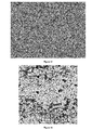
- microstructure of a metallic part is shown at 4'800 dpi.
- the size of the microstructure elements are about 47 um.
- the field of view is about 10mm x 10mm.
- microstructure of a piece of polymer is shown at 2'400 dpi.
- the size of the defaults is about 349 um and the field of view is 50mm x 50mm.
- microstructure of an offset printed label is shown at 2'400dpi.
- the size of the defaults is about 42 um and the field of view is 2.5mm x 2.5mm.
- the coated part of a dial is shown at 10'837 dpi.
- the size of the details is about 58 um and the field of view is 1.2mm x 1.2mm.
- the details are uniformly spread across the image. Thanks to some image processing steps that are described in more details in the next sections, it is possible to obtain a uniform variation of the microstructures inside an image. Furthermore it was noticed that these microstructures were randomly spread on the item. This insures randomness from item to item.
- FIG. 19 is the schema representing the different dpi necessary for each level of the fingerprint.
- the different technologies are represented on the vertical axis (191) and the different dpi's are represented on the horizontal axis (192). There are always gray zones and white zones for each technology.
- the white zone represents the best dpi zone for the technology whereas the gray zone shows up to where it is possible to extend it.
- Unique fingerprint (195) has no upper boundary as the dpi to identify an item uniquely depends on the size of its microstructures. Unique fingerprint may also extend in some cases in the lower resolutions area (like leather for instance and more generally any natural material).
- Microscopic fingerprint (194) and macroscopic fingerprint (193) are basically two times the same technology. The only difference is that, in microscopic fingerprint, microstructures are considered whereas in macroscopic fingerprint macrostructures are considered. An upper boundary is therefore necessary because it defines the boundary between microscopic and unique and between macroscopic and microscopic. For the same reasons a down boundary is also required.
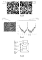
- FIG. 8 shows the contours of text printed in rotogravure technology and how they vary between two successive prints.
- these contours have some features which are common between two contours (like 81 and 83 for instance) but also features which are different (like 82 and 84).
- Common features i.e. micro fingerprint
- common features typically have sizes that extend on a larger area than different features (i.e. unique fingerprint). This means in particular that contour matching can be performed using high frequencies of the signal.
- the similar large features come from cells location on the cylinder and the variation between two prints comes from the texture of the paper and how the ink deposits on the surface.
- the print randomness depends on several parameters, including the location of the cells engraved on the cylinder, the viscosity of the ink, the printing speed and the micro structure of the carton, the ink filling of the cylinder cells, etc. on one hand and the ink absorption on the paper on the other hand. All these parameters have an influence on the randomization of the shape contours or tint area. It is this randomness that can be used to identify individual products but also production batches, individual cylinder used for production or the printing works. It is also possible to deduce the aging of the cylinder (and hence at which approximate time a product was printed) from the images (for instance, the doctor blade that pushes the ink in a rotogravure cylinder progressively wears the engraved cells after millions of rotations).
- a logo is engraved at the back of a watch, it can be done chemically. So each engraved logo is unique as it can be seen in Figure 10 .
- 101 is a part of a chemically engraved logo of a back of a watch and 102 is the same part of the same logo on another watch of the same model. This is an example of unique fingerprint.
- Chemical etching is usually done on metallic surfaces but can also be applied to any other material.
- the back of the watch can also be stamped instead of chemically engraved.
- the field of view of the acquisition device should be much lower than in the preceding case for the same dpi. If the field of view is not little enough, it will only be possible to distinguish the stamp used to stamp the surface. But it is shown in Figure 20 that with a sufficiently big ratio between the dpi and the field of view, it is possible to see differences between the two items.
- the field of view is about 0.4 x 0.6 mm and the dpi is 10'837. So the ratio is about 25'000. This is an example of unique fingerprint.
- stamping is usually done on metallic material but it can also be done on any other material.
- any surface treatment or machining process resulting in noisy images or images with sufficient entropy may be used as a template for image retrieval. This includes in particular surface sanding, milling, spinning, drilling, etc.
- Figure 23 shows the difference of microstructures of coating at about 10'000 dpi with a 1x1 mm field of view. Coating can be applied to any material.
- each drop has its own shape and location. Labels are taken as an example. A label will be the same than all the other labels that are printed with the same printer on the same position of the offset sheet. On the contrary, a label printed by another printer or in another position of the offset sheet will look different. This is shown in Figure 25 . 251 and 252
- this technology can be extended by reducing the dpi in order to check if the overall graphical design of a box matches with the original design.
- This approach is for instance applicable to fake medicines that are sold on the Internet. This is a particular example of macroscopic fingerprint.
- a specific area has to be defined; the same area will be used for recording and future comparisons.
- the location of this area is optimal when its microstructures are uniformly spread out the image.
- Such an area can be retrieved automatically. Indeed, this area should match some specific mathematical requirements enabling to maximize detection rate and minimize false detections.
- images having statistics of uniform noise have proven to perform particularly well.
- Many approaches are available in the literature which enable the measurement of noise characteristics and may be used here.
- One example is to analyze the Fourier transform of the image, for instance white noise is known for having a flat spectrum. It is also possible to derive the optimal dpi resolution by analyzing with part of the Fourier spectrum characterizes a noise signal. This is shown in Figure 26 .
- 262 is the uniform Fourier Transform of 261 which contains microstructures that are uniformly spread out the image. It is possible to take one or two images at two different levels of details for pre-processing steps purpose. This depends on the future processing and can be determined by the material, the shape and the application.
- the corresponding image has to be stored and will constitute the record set (typically accessed through database tools).
- the basic requirement is to obtain an image of the microstructures that contains a sufficient amount of details to enable a unique identification (knowing that the total amount data will also increase with the database size).
- This amount of details is of course directly linked to the image size and to the microstructure element sizes.
- a theoretical boundary of the minimum image size for a given database size may be computed in the particular case of black and white image. Indeed, for a 5x5 pixels image, the number of different possible images would be 2 ⁇ 25 ⁇ 33 millions. This means that an ideal random black and white structure could be uniquely identified in a database of 33 millions reference images. In practice much larger images (up to a size of 100 times more in each dimension) have to be used and database size may become an issue.
- wavelet compression may also be useful, as it would benefit to the image retrieval task. Indeed the image retrieval can then be hierarchically performed on increasing wavelets frequencies of the images (thus speeding up the retrieval process for instance). Other information may also be stored in place or in complement of the scanned images. For instance, invariant features (image moments for example, statistical properties, etc), parameters related to contours, minutiae features or any other information able to speed up the retrieval process or increase the matching reliability.
- the general strategy is depicted in the schema of Figure 28 .
- the picture is taken, its position and rotation in respect to the original image is not known.
- the new coordinates x' and y' have to be deduced from the translation vector, the angle of rotation and the old x and y coordinates.
- the rotation can be retrieved by a Fourier transform.
- the location can be retrieved by a 1 D projection for example.
- masking (282) has to be computed, depending on the size of the field of view and on the size of the microstructures.
- all the pre-processing operations (283), such as flattening can be computed.
- the image matching (284) is performed.
- a metric enables to decide that one or several images from the record set do actually match to a certain level.
- the number of images belonging to this matching set should be 1 (cardinality equal to singleton).
- this image will identify a unique object (and any useful side information, typically by using a database access) or set of objects with common features.
- common feature can be a mould identifier.
- the rotation angle can be found if the picture includes some anisotropic visual information which is identical for all items. For instance, if there is a line across the picture, it will be possible to use this information in order to exactly find the rotation angle. Of course this line will be a drawback for cross-correlation purposes. That is why it is possible to take different pictures from the item to verify, even at different resolutions.
- Each image can then be assigned to a specific operation.
- Transform domains may be used to aid the extraction and characterization of anisotropic information. For instance, the Hough transform or the Fourier transform may be used. In the case of the Fourier transform, the spatial anisotropy of the image will result in a line in the modulus of the Fourier transform of this image. This is shown in Figure 11 .
- 111 shows the Fourier transform and 112 shows the angle, which is a radial sum of the value of the Fourier Transform related to each angle.
- the spatial anisotropy of the image may contain several main directions (for instance a square contains two main direction which are perpendicular) which results in different candidate angles.
- the right angle can be determined by testing each of the possible angles.
- this direction is perpendicular to the angle found by the sum over the axes. That is why, in Figure 11 , the sum is done over an angle "a" in 111 and the result is displayed for an angle "a+90".
- a testing procedure consists in cross-correlation with a reference image.
- the image used for rotation detection (and the corresponding reference image) may be taken at resolution (dpi) and at a location that is different from the image used to characterize the microstructure of a surface.
- the angle value can be more precisely determined by a trial error procedure around the angle previously found. For instance, it is possible to iterate between -1 to +1 degrees by steps 0.1 degrees, computing the SNR for each angle, and keep the angle that results in the best SNR.
- the basic idea consists in taking a circular shape around a point of interest and unwarping to a rectangular shape.
- Figure 32 describes this process.
- 321 is the circular donut around a point of interest that has to be cut. The cut is done in AB. A is the origin and B is the end of the new image.
- the circular shape is then mapped (or unwarped) on a rectangular (322) shape using standard image interpolation methods.
- image can be compared (for instance using cross-correlation) with a template image that has been generated using the same process.
- the location of cross-correlation peak will vary with the rotation angle, but the SNR value will not be affected. Therefore this technique enables to detect matching images without the need for a prior compensation in rotation.
- a general approach to compensate for translation is to use image that include feature points.
- one approach is to acquire a low resolution image of the object.
- the cross-correlation of this image with a recorded template (that will be unique for the whole database) enables to find exactly the X/Y position of the snapshot and therefore to determine the location of the region of interest that should be acquired at higher resolution.
- the cross-correlation is typically computed on flattened images.
- One way to do flattening is to do a mathematical operation that consists in taking the difference between an image and its frequency low-passed version. The goal of this operation is to remove macroscopic color variations across the image and which are not significant, like lighting variations for instance. In particular enables to set all the borders of the image to the same value, which avoid border effects during a cross-correlation based on Fourier Transform (FFT based correlation implicitly tiles the image, artificially creating border effects between tiles if image is not uniform).
- FFT based correlation implicitly tiles the image, artificially creating border effects between tiles if image is not uniform.
- FIG 29 the effect of flattening is shown.
- 291 and 293 are images that have not been flattened.
- 292 and 294 are the same images after flattening.
- the cross-correlations are computed with a template image that should match with the image 293 but that should not match with the image 291.
- the cross-correlations for each image are shown on the right side. It can be seen that the cross-correlation image 295 and 296 show no correlation peak, which is normal.
- the image 297 does not show a clear cross-correlation peak although the image should normally match with the template.
- the cross-correlation of the flattened image 298 shows a clear cross-correlation peak.
- the blurring radius in pixels
- the blurring radius will typically have a value close to the microstructures size measured in pixels.
- the field of view has a size that implies that some non interesting details are visible, they should be masked.
- One possibility to do the masking is to put all the value that have not to be taken into account to the mean value of the image.
- FIG. 31 The importance of masking disturbing elements is shown in Figure 31 . It is shown that, without masking, the cross-correlation (314) of a template (311) and another picture of the same item (312) is not better than the cross-correlation (315) of the template (311) with a picture of another item (313). Even worse, the cross-correlation (315) of the template (311) and the picture of the other item (313) has a good peak because of macroscopic cross-correlation. This kind of mismatching is a false-positive detection that must be absolutely avoided. It is shown that it is possible to prevent such mismatch by padding to the mean value the disturbing element.
- the image matching purpose is to define a metric which enables to decide if two images are similar.
- a perfect similarity can be characterized by a null Mean Square Error between two images and a matching metric will typically converge to a known value in this case.
- Image matching can be performed using cross-correlation or matching in transform domains (Hough or Fourier spaces for instance) possibly enhanced by log-polar transforms in order to be invariant with scale or rotation. It is also possible to use spatially transform domain in order to map the image in a way that is more efficient for matching purposes. For instance, it is possible to compute a 1 D profile corresponding to the sum of color intensity along each line and use such 1 D function in conjunction with 1 D signal matching algorithms for fast retrieval (possibly refined with a vertical profile). Another spatially transform domain was shown in previous section and illustrated in Figure 32 . The so-called “minutiae” approach used in fingerprint matching can also be used. Its principle is to use only a limited number of localized feature points instead of using the
- contour matching techniques may then be used as for instance Fourier descriptors or 1 D cross-correlation (the contour being converted to a 1 D signal).
- Artificial neural networks may also be used in order to perform the image matching or the contour matching operation. More generally, let the image be described by a given set of parameters. Any classifier may be used to find the best match in a database. The choice of the best classifier will depend on the computational requirements, the image statistics, etc.
- Figure 8 corresponds to a letter which orientation, scale and spatial position on the item to verify is known. Therefore an automatic scanning system may be able to locate this letter with a low-resolution scan, then rescan the letter with a high resolution and finally compensate for the rotation.
- the cross-correlation is particularly suitable for matching images which contain noise. Indeed, it can be used basically for any kind of uniform noise without special tuning or adaptations.
- cross-correlations which can also perform efficiently in the case of microstructure. This is for instance the case of phase correlation and cross-correlation with special padding strategy. Indeed, in the above formula the indices k'+k or l'+l may exceed the image size in the finite case and a strategy has to be followed to define which values should be used in such cases. Some of these strategies include padding the image with values varying symmetrically or anti-symmetrically (left/right and up/down) across their borders, or padding with a fixed value (the mean value for instance).
- This value characterizes the signal to noise ratio (SNR) of the cross-correlation image and is measured in decibels (dB).
- SNR signal to noise ratio
- dB decibels
- cross-correlation is robust against some modifications of the item. In particular it is robust against adding adhesive or static layer, adding dust, damaging by scratching and all other damage that let up to half of the information. It also has to be noticed that this method is robust throughout glasses, even watch glass, flat or convex, with or without anti-reflective coating on it.
- the size in pixel of the images to cross-correlate as well as their dpi has to be chosen depending on the size and the number of the microstructures.
- a detection strategy consists in performing the detection in several stages. A first stage is performed with downsampled versions of the snapshot and template images and then the next stage use larger versions of the snapshots and templates.
- cross-correlations are first computed with a set of X0 templates using an image size of 2 n x 2 n pixels (the same method may of course be used for non square images or non integer power of 2 image sizes).
- a number X12 of cross-correlation images have an SNR over a given threshold t1 and are then selected as candidates for a second test with larger image size 2 n+1 .
- Such strategy is not limited to the case of cross-correlation and can potentially be applied with any matching metric.
Priority Applications (2)
| Application Number | Priority Date | Filing Date | Title |
|---|---|---|---|
| EP15178070.7A EP2960830B1 (de) | 2005-09-05 | 2006-09-05 | Mittel zur verwendung einer mikrostruktur aus materialoberfläche als eindeutige kennung |
| EP18174438.4A EP3399462A1 (de) | 2005-09-05 | 2006-09-05 | Mittel zur verwendung einer mikrostruktur aus materialoberfläche als eindeutige kennung |
Applications Claiming Priority (3)
| Application Number | Priority Date | Filing Date | Title |
|---|---|---|---|
| EP05108123 | 2005-09-05 | ||
| EP15178070.7A EP2960830B1 (de) | 2005-09-05 | 2006-09-05 | Mittel zur verwendung einer mikrostruktur aus materialoberfläche als eindeutige kennung |
| EP06793252.5A EP2024899B1 (de) | 2005-09-05 | 2006-09-05 | Mittel zur verwendung einer mikrostruktur aus materialoberfläche als eindeutige kennung |
Related Parent Applications (2)
| Application Number | Title | Priority Date | Filing Date |
|---|---|---|---|
| EP06793252.5A Division-Into EP2024899B1 (de) | 2005-09-05 | 2006-09-05 | Mittel zur verwendung einer mikrostruktur aus materialoberfläche als eindeutige kennung |
| EP06793252.5A Division EP2024899B1 (de) | 2005-09-05 | 2006-09-05 | Mittel zur verwendung einer mikrostruktur aus materialoberfläche als eindeutige kennung |
Related Child Applications (2)
| Application Number | Title | Priority Date | Filing Date |
|---|---|---|---|
| EP18174438.4A Division-Into EP3399462A1 (de) | 2005-09-05 | 2006-09-05 | Mittel zur verwendung einer mikrostruktur aus materialoberfläche als eindeutige kennung |
| EP18174438.4A Division EP3399462A1 (de) | 2005-09-05 | 2006-09-05 | Mittel zur verwendung einer mikrostruktur aus materialoberfläche als eindeutige kennung |
Publications (2)
| Publication Number | Publication Date |
|---|---|
| EP2960830A1 true EP2960830A1 (de) | 2015-12-30 |
| EP2960830B1 EP2960830B1 (de) | 2018-07-04 |
Family
ID=37533241
Family Applications (3)
| Application Number | Title | Priority Date | Filing Date |
|---|---|---|---|
| EP18174438.4A Pending EP3399462A1 (de) | 2005-09-05 | 2006-09-05 | Mittel zur verwendung einer mikrostruktur aus materialoberfläche als eindeutige kennung |
| EP15178070.7A Active EP2960830B1 (de) | 2005-09-05 | 2006-09-05 | Mittel zur verwendung einer mikrostruktur aus materialoberfläche als eindeutige kennung |
| EP06793252.5A Active EP2024899B1 (de) | 2005-09-05 | 2006-09-05 | Mittel zur verwendung einer mikrostruktur aus materialoberfläche als eindeutige kennung |
Family Applications Before (1)
| Application Number | Title | Priority Date | Filing Date |
|---|---|---|---|
| EP18174438.4A Pending EP3399462A1 (de) | 2005-09-05 | 2006-09-05 | Mittel zur verwendung einer mikrostruktur aus materialoberfläche als eindeutige kennung |
Family Applications After (1)
| Application Number | Title | Priority Date | Filing Date |
|---|---|---|---|
| EP06793252.5A Active EP2024899B1 (de) | 2005-09-05 | 2006-09-05 | Mittel zur verwendung einer mikrostruktur aus materialoberfläche als eindeutige kennung |
Country Status (6)
| Country | Link |
|---|---|
| US (1) | US8180174B2 (de) |
| EP (3) | EP3399462A1 (de) |
| DK (1) | DK2024899T3 (de) |
| ES (1) | ES2561058T3 (de) |
| HK (1) | HK1122887A1 (de) |
| WO (1) | WO2007028799A1 (de) |
Families Citing this family (101)
| Publication number | Priority date | Publication date | Assignee | Title |
|---|---|---|---|---|
| US7162035B1 (en) | 2000-05-24 | 2007-01-09 | Tracer Detection Technology Corp. | Authentication method and system |
| US8171567B1 (en) | 2002-09-04 | 2012-05-01 | Tracer Detection Technology Corp. | Authentication method and system |
| MXPA06010402A (es) | 2004-03-12 | 2007-01-19 | Ingenia Technology Ltd | Metodos, productos y aparatos para la verificacion de autenticidad. |
| EP2081130B1 (de) | 2004-03-12 | 2013-07-24 | Ingenia Holdings Limited | Verfahren und Vorrichtung zur Erschaffung verifizierbarer Druckartikel und deren nachträglichen Prüfung |
| GB2417592B (en) | 2004-08-13 | 2006-07-26 | Ingenia Technology Ltd | Authenticity verification of articles |
| KR101223204B1 (ko) | 2005-07-27 | 2013-01-17 | 인제니아 홀딩스 리미티드 | 진품 검증 |
| US9208394B2 (en) | 2005-09-05 | 2015-12-08 | Alpvision S.A. | Authentication of an article of manufacture using an image of the microstructure of it surface |
| EP2110776B1 (de) | 2005-12-23 | 2012-10-31 | Ingenia Holdings Limited | Optische Authentifizierung |
| EP1942443A1 (de) * | 2007-01-05 | 2008-07-09 | Siemens Aktiengesellschaft | Verfahren und Vorrichtung zum Identifizieren von Bauteilen |
| US20080272585A1 (en) | 2007-04-26 | 2008-11-06 | Bowe Bell + Howell Company | Method and programmable product for unique document identification using stock and content |
| US7995196B1 (en) | 2008-04-23 | 2011-08-09 | Tracer Detection Technology Corp. | Authentication method and system |
| EP2112834A1 (de) * | 2008-04-24 | 2009-10-28 | Psytechnics Limited | Verfahren und Gerät zur Normalisierung von Bildsignalen |
| FR2932588B1 (fr) | 2008-06-12 | 2010-12-03 | Advanced Track & Trace | Procede et dispositif de lecture d'une caracteristique physique sur un objet |
| GB2462409A (en) * | 2008-07-11 | 2010-02-10 | Ingenia Holdings | Signature of moulded article |
| GB2466465B (en) * | 2008-12-19 | 2011-02-16 | Ingenia Holdings | Authentication |
| GB2466311B (en) | 2008-12-19 | 2010-11-03 | Ingenia Holdings | Self-calibration of a matching algorithm for determining authenticity |
| US8630489B2 (en) | 2009-05-05 | 2014-01-14 | Microsoft Corporation | Efficient image matching |
| US8290205B2 (en) * | 2009-06-25 | 2012-10-16 | Eastman Kodak Company | Dating images from scanned watermarks |
| US9749607B2 (en) | 2009-07-16 | 2017-08-29 | Digimarc Corporation | Coordinated illumination and image signal capture for enhanced signal detection |
| DE102009037626A1 (de) | 2009-08-14 | 2011-02-17 | Giesecke & Devrient Gmbh | Sichere Kennzeichnung eines Produkts |
| GB2476226B (en) | 2009-11-10 | 2012-03-28 | Ingenia Holdings Ltd | Optimisation |
| WO2011061862A1 (ja) * | 2009-11-17 | 2011-05-26 | 株式会社日立製作所 | 生体情報を用いた認証システム及び認証装置 |
| WO2011104736A1 (en) | 2010-02-26 | 2011-09-01 | Faber Industrie S.P.A. | Method and system for generating tracing information for gas cylinders |
| US8526743B1 (en) | 2010-11-01 | 2013-09-03 | Raf Technology, Inc. | Defined data patterns for object handling |
| US9443298B2 (en) | 2012-03-02 | 2016-09-13 | Authentect, Inc. | Digital fingerprinting object authentication and anti-counterfeiting system |
| US8774455B2 (en) | 2011-03-02 | 2014-07-08 | Raf Technology, Inc. | Document fingerprinting |
| US9152862B2 (en) | 2011-09-15 | 2015-10-06 | Raf Technology, Inc. | Object identification and inventory management |
| WO2013018615A1 (ja) * | 2011-07-29 | 2013-02-07 | 日本電気株式会社 | 照合・検索システム、照合・検索サーバ、画像特徴抽出装置、照合・検索方法及びプログラム |
| US9842285B2 (en) | 2011-07-29 | 2017-12-12 | Nec Corporation | Collation/retrieval system, collation/retrieval server, image feature extraction apparatus, collation/retrieval method, and program |
| US10341555B2 (en) | 2011-12-02 | 2019-07-02 | Chromologic Llc | Characterization of a physical object based on its surface roughness |
| CN104205128B (zh) * | 2012-01-23 | 2018-02-16 | 破赛普提医药有限公司 | 自动化药物药丸识别 |
| ITTO20120275A1 (it) * | 2012-03-27 | 2013-09-28 | Dacom S P A | Metodo e sistema di individuazione di un segno grafico non convenzionale all'interno di un'immagine digitale o digitalizzata |
| EP2866193B1 (de) * | 2012-06-22 | 2019-06-12 | NEC Corporation | Verifizierungsverfahren, verifizierungssystem, verifizierungsvorrichtung und programm dafür |
| EP2866194A4 (de) * | 2012-06-22 | 2016-07-06 | Nec Corp | Verifizierungsverfahren, verifizierungssystem, vorrichtung, verifizierungsvorrichtung und programm |
| US9031281B2 (en) * | 2012-06-22 | 2015-05-12 | Microsoft Technology Licensing, Llc | Identifying an area of interest in imagery |
| DE102012017398A1 (de) | 2012-09-03 | 2013-02-21 | Heidelberger Druckmaschinen Ag | Sicherheitsetikett mit einem Zufallsmuster und einer Repräsentation des Zufallsmusters |
| US9014428B2 (en) * | 2013-02-15 | 2015-04-21 | Sony Corporation | Object detection using difference of image frames |
| EP2973234B1 (de) * | 2013-03-12 | 2018-10-24 | Arizona Board of Regents, a Body Corporate of the State of Arizona acting for and on behalf of Arizona State University | Dendritische strukturen und etiketten |
| WO2014142099A1 (ja) * | 2013-03-12 | 2014-09-18 | 日本電気株式会社 | 識別方法、識別システム、識別装置及びプログラム |
| US10088658B2 (en) * | 2013-03-18 | 2018-10-02 | General Electric Company | Referencing in multi-acquisition slide imaging |
| WO2014163014A1 (ja) | 2013-04-04 | 2014-10-09 | 日本電気株式会社 | 識別システム、識別方法、照合装置及びプログラム |
| US9594993B2 (en) | 2013-11-07 | 2017-03-14 | Scantrush Sa | Two dimensional barcode and method of authentication of such barcode |
| WO2015089346A1 (en) | 2013-12-13 | 2015-06-18 | Battelle Memorial Institute | Electronic component classification |
| US10424038B2 (en) | 2015-03-20 | 2019-09-24 | Digimarc Corporation | Signal encoding outside of guard band region surrounding text characters, including varying encoding strength |
| US9635378B2 (en) | 2015-03-20 | 2017-04-25 | Digimarc Corporation | Sparse modulation for robust signaling and synchronization |
| EP2921989A1 (de) | 2014-03-17 | 2015-09-23 | Université de Genève | Verfahren zur Erkennung und/oder Echtheitsprüfung von Gegenständen mittels mobiler Geräte |
| WO2016073910A1 (en) | 2014-11-07 | 2016-05-12 | Arizona Board Of Regents On Behalf Of Arizona State University | Information coding in dendritic structures and tags |
| US10956732B2 (en) * | 2014-11-21 | 2021-03-23 | Guy Le Henaff | System and method for detecting the authenticity of products |
| DE102014224557A1 (de) * | 2014-12-01 | 2016-06-02 | Osram Gmbh | Bildverarbeitung mittels Kreuzkorrelation |
| CN107110781A (zh) * | 2014-12-18 | 2017-08-29 | 3M创新有限公司 | 用于自动防伪的材料批量认证 |
| US9754341B2 (en) | 2015-03-20 | 2017-09-05 | Digimarc Corporation | Digital watermarking and data hiding with narrow-band absorption materials |
| US10783601B1 (en) | 2015-03-20 | 2020-09-22 | Digimarc Corporation | Digital watermarking and signal encoding with activable compositions |
| RU2746027C2 (ru) | 2015-04-09 | 2021-04-06 | Филигрэйд Б.В. | Способ проверки подлинности печатного изделия и терминал обработки данных |
| JP6822396B2 (ja) * | 2015-04-10 | 2021-01-27 | 日本電気株式会社 | 位置特定装置、位置特定方法及びプログラム |
| US10303988B1 (en) * | 2015-08-14 | 2019-05-28 | Digimarc Corporation | Visual search methods and systems |
| US10102407B2 (en) * | 2015-09-21 | 2018-10-16 | Robert Bosch Gmbh | Method for generating a unique package identifier based on physical properties of a package |
| CN106682912B (zh) | 2015-11-10 | 2021-06-15 | 艾普维真股份有限公司 | 3d结构的认证方法 |
| WO2017083841A1 (en) | 2015-11-13 | 2017-05-18 | University Of Maryland, College Park | Counterfeit detection scheme using paper surfaces and mobile cameras |
| JP2017099616A (ja) * | 2015-12-01 | 2017-06-08 | ソニー株式会社 | 手術用制御装置、手術用制御方法、およびプログラム、並びに手術システム |
| US10572883B2 (en) | 2016-02-19 | 2020-02-25 | Alitheon, Inc. | Preserving a level of confidence of authenticity of an object |
| US10867301B2 (en) | 2016-04-18 | 2020-12-15 | Alitheon, Inc. | Authentication-triggered processes |
| US10614302B2 (en) | 2016-05-26 | 2020-04-07 | Alitheon, Inc. | Controlled authentication of physical objects |
| EP3252680B1 (de) | 2016-05-31 | 2019-12-25 | Agfa Nv | Authentifizierungsverfahren eines zweidimensionalen strichcodes |
| US10740767B2 (en) | 2016-06-28 | 2020-08-11 | Alitheon, Inc. | Centralized databases storing digital fingerprints of objects for collaborative authentication |
| US10915612B2 (en) | 2016-07-05 | 2021-02-09 | Alitheon, Inc. | Authenticated production |
| US10902540B2 (en) | 2016-08-12 | 2021-01-26 | Alitheon, Inc. | Event-driven authentication of physical objects |
| US10839528B2 (en) | 2016-08-19 | 2020-11-17 | Alitheon, Inc. | Authentication-based tracking |
| CN106874818B (zh) | 2016-08-30 | 2019-11-22 | 阿里巴巴集团控股有限公司 | 一种数字对象唯一标识符doi识别方法与装置 |
| EP3593274A1 (de) | 2017-03-10 | 2020-01-15 | Fraunhofer-Gesellschaft zur Förderung der angewandten Forschung e.V. | Verfahren und system zur markierung und zum nachweis einer klonresistenten physikalischen einheit |
| CN110770711B (zh) | 2017-03-31 | 2023-12-22 | 3M创新有限公司 | 基于图像的伪造品检测 |
| US10789550B2 (en) | 2017-04-13 | 2020-09-29 | Battelle Memorial Institute | System and method for generating test vectors |
| MX2019012706A (es) | 2017-04-24 | 2019-12-16 | Patek Philippe Sa Geneve | Metodo para identificar un reloj. |
| EP3639188A4 (de) | 2017-06-16 | 2021-03-17 | Arizona Board of Regents on behalf of Arizona State University | Polarisiertes scannen von dendritischen identifikatoren |
| EP3435287A3 (de) | 2017-07-25 | 2019-05-01 | Alitheon, Inc. | Modellbasierte digitale fingerabdrucknahme |
| JP6853891B2 (ja) * | 2017-08-31 | 2021-03-31 | 富士フイルム富山化学株式会社 | 薬剤監査装置、画像処理装置、画像処理方法及びプログラム |
| US11062108B2 (en) | 2017-11-07 | 2021-07-13 | Digimarc Corporation | Generating and reading optical codes with variable density to adapt for visual quality and reliability |
| US10896307B2 (en) | 2017-11-07 | 2021-01-19 | Digimarc Corporation | Generating and reading optical codes with variable density to adapt for visual quality and reliability |
| US10872392B2 (en) | 2017-11-07 | 2020-12-22 | Digimarc Corporation | Generating artistic designs encoded with robust, machine-readable data |
| US11847661B2 (en) | 2017-11-30 | 2023-12-19 | 3M Innovative Properties Company | Image based counterfeit detection |
| US11087013B2 (en) | 2018-01-22 | 2021-08-10 | Alitheon, Inc. | Secure digital fingerprint key object database |
| CN108600450B (zh) * | 2018-04-24 | 2020-12-01 | 业成科技(成都)有限公司 | 面板结构 |
| US11598015B2 (en) | 2018-04-26 | 2023-03-07 | Arizona Board Of Regents On Behalf Of Arizona State University | Fabrication of dendritic structures and tags |
| WO2019246132A1 (en) * | 2018-06-18 | 2019-12-26 | Digimarc Corporation | Methods and arrangements for reconciling data from disparate data carriers |
| US10885415B2 (en) | 2018-09-07 | 2021-01-05 | Transpacks Technologies Private Limited | Anti-counterfeiting mark with 3-D features |
| WO2020110269A1 (ja) * | 2018-11-29 | 2020-06-04 | 日本電気株式会社 | 個体識別装置 |
| EP3671535A1 (de) * | 2018-12-19 | 2020-06-24 | Fairchild Fasteners Europe - VSD GmbH | Verfahren zum zusammenstellen einer bauteilsammlung sowie entsprechende anlage |
| US10963670B2 (en) | 2019-02-06 | 2021-03-30 | Alitheon, Inc. | Object change detection and measurement using digital fingerprints |
| WO2020196376A1 (ja) * | 2019-03-26 | 2020-10-01 | 日本電気株式会社 | 認証方法、認証装置、プログラム |
| EP3734506A1 (de) | 2019-05-02 | 2020-11-04 | Alitheon, Inc. | Automatisierte lokalisierung und erfassung von authentifizierungsbereichen |
| EP3736717A1 (de) | 2019-05-10 | 2020-11-11 | Alitheon, Inc. | Verfahren und system für digitale fingerabdrücke in einer schleifenkette |
| US11238146B2 (en) | 2019-10-17 | 2022-02-01 | Alitheon, Inc. | Securing composite objects using digital fingerprints |
| US11151583B2 (en) * | 2019-10-21 | 2021-10-19 | Entrupy Inc. | Shoe authentication device and authentication process |
| EP3859603A1 (de) | 2020-01-28 | 2021-08-04 | Alitheon, Inc. | Tiefenbasierte digitale fingerabdruckerstellung |
| EP3885984A1 (de) | 2020-03-23 | 2021-09-29 | Alitheon, Inc. | Gesichtsbiometriesystem und verfahren zur verwendung von digitalen fingerabdrücken |
| EP3885982A3 (de) | 2020-03-23 | 2021-12-22 | Alitheon, Inc. | Handbiometriksystem und verfahren unter verwendung von digitalen fingerabdrücken |
| US11948377B2 (en) | 2020-04-06 | 2024-04-02 | Alitheon, Inc. | Local encoding of intrinsic authentication data |
| US11663849B1 (en) | 2020-04-23 | 2023-05-30 | Alitheon, Inc. | Transform pyramiding for fingerprint matching system and method |
| EP3926496A1 (de) | 2020-06-17 | 2021-12-22 | Alitheon, Inc. | Besicherte digitale sicherheitstoken |
| DE102020215403A1 (de) | 2020-12-07 | 2022-06-09 | Robert Bosch Gesellschaft mit beschränkter Haftung | Verfahren zur Prüfung der Herkunft und/oder Identität eines Produkts |
| EP4102399A1 (de) | 2021-06-08 | 2022-12-14 | Université de Genève | Objektauthentifizierung mittels digitaler blaupausen und physischer fingerabdrücke |
| DE102022122498A1 (de) | 2021-10-07 | 2023-04-13 | Heidelberger Druckmaschinen Aktiengesellschaft | Verfahren zum Herstellen und Serialisieren einer Mehrzahl von Druckprodukten |
Citations (23)
| Publication number | Priority date | Publication date | Assignee | Title |
|---|---|---|---|---|
| US4490849A (en) * | 1982-03-04 | 1984-12-25 | Grumman Aerospace Corporation | Correlation plane recognition processor |
| GB2221870A (en) | 1988-05-31 | 1990-02-21 | De La Rue Co Plc | Security device |
| WO1992015965A1 (en) * | 1991-03-04 | 1992-09-17 | David Sarnoff Research Center, Inc. | Fast and efficient search method for graphical data |
| US5454045A (en) | 1994-04-15 | 1995-09-26 | Battelle Memorial Institute | Apparatus and method for identification and recognition of an item with ultrasonic patterns from item subsurface micro-features |
| US5975581A (en) | 1998-08-25 | 1999-11-02 | Sentry Technology Corp. | System for confirming the authenticity of an article using a magnetic reader |
| US6030657A (en) | 1994-11-01 | 2000-02-29 | Dna Technologies, Inc. | Labeling technique for countering product diversion and product counterfeiting |
| US6384409B1 (en) | 1998-04-22 | 2002-05-07 | Mqs, Inc. | Optical tracking system |
| US6459175B1 (en) | 1997-11-17 | 2002-10-01 | Patrick H. Potega | Universal power supply |
| US6461987B1 (en) | 1995-06-01 | 2002-10-08 | Mark Leroy Walker | Continuous micro-label apparatus and process |
| US20030014647A1 (en) | 2000-02-04 | 2003-01-16 | Francis Bourrieres | Method and device for reading authentication means and adapted identification means |
| US6547137B1 (en) | 2000-02-29 | 2003-04-15 | Larry J. Begelfer | System for distribution and control of merchandise |
| US6565000B2 (en) | 1997-06-24 | 2003-05-20 | Richard P. Sehr | System and methods utilizing passport documents |
| US6584214B1 (en) | 1999-04-23 | 2003-06-24 | Massachusetts Institute Of Technology | Identification and verification using complex, three-dimensional structural features |
| US6629061B1 (en) | 2000-07-31 | 2003-09-30 | Avaya Technology Corp. | Automatic concealment of product serialization information |
| US6706314B2 (en) | 2001-03-15 | 2004-03-16 | Amesbury Trust | Method of labelling an object |
| US20040079800A1 (en) * | 2002-10-29 | 2004-04-29 | Fuji Xerox Co., Ltd. | Document verification system |
| US6776341B1 (en) | 1994-08-05 | 2004-08-17 | Scott L. Sullivan | Pill printing and identification |
| US6869015B2 (en) | 2001-05-30 | 2005-03-22 | Sandia National Laboratories | Tamper-indicating barcode and method |
| US20050075984A1 (en) | 2003-10-02 | 2005-04-07 | Novatec Sa | Method to make transactions secure by means of cards having uniqe and non-reproducible identifiers |
| US6920437B2 (en) | 1996-07-15 | 2005-07-19 | Intelli-Check, Inc. | Authentication system for identification documents |
| US6922687B2 (en) | 2001-12-21 | 2005-07-26 | Barca, L.L.C. | Closed loop asset management process |
| WO2005122100A1 (fr) | 2004-05-11 | 2005-12-22 | Signoptic Technologies | Procede de reconnaissance et de suivi de supports fibreux, ainsi que les applications d'un tel procede dans le domaine informatique notamment |
| WO2006078651A1 (en) | 2005-01-21 | 2006-07-27 | The Boeing Company | Control surface assemblies with torque tube base |
Family Cites Families (11)
| Publication number | Priority date | Publication date | Assignee | Title |
|---|---|---|---|---|
| US4371866A (en) * | 1980-11-21 | 1983-02-01 | The United States Of America As Represented By The Secretary Of The Army | Real-time transformation of incoherent light images to edge-enhanced darkfield representation for cross-correlation applications |
| EP0578875A1 (de) * | 1992-07-17 | 1994-01-19 | Recognition International Inc. | Normalisierender Korrelator für Videoverarbeitung |
| EP1153373B1 (de) | 1999-12-08 | 2003-05-28 | Valentin Alexandrovich Mischenko | Verfahren und system zur authentifizierung von artikeln |
| AU2003234699A1 (en) * | 2002-04-09 | 2003-10-27 | The Escher Group, Ltd. | System and method for authentication of a workpiece using three dimensional shape recovery |
| JP3917572B2 (ja) * | 2003-09-05 | 2007-05-23 | 株式会社東芝 | 電子透かし検出方法及び装置 |
| EP2081130B1 (de) | 2004-03-12 | 2013-07-24 | Ingenia Holdings Limited | Verfahren und Vorrichtung zur Erschaffung verifizierbarer Druckartikel und deren nachträglichen Prüfung |
| GB2417707B (en) | 2004-08-13 | 2006-07-26 | Ingenia Technology Ltd | Methods and apparatuses for creating authenticatable printed articles and subsequently verifying them |
| MXPA06010402A (es) | 2004-03-12 | 2007-01-19 | Ingenia Technology Ltd | Metodos, productos y aparatos para la verificacion de autenticidad. |
| GB2444139B (en) | 2004-08-13 | 2008-11-12 | Ingenia Technology Ltd | Authenticity verification methods products and apparatuses |
| GB2417592B (en) | 2004-08-13 | 2006-07-26 | Ingenia Technology Ltd | Authenticity verification of articles |
| GB2426100B (en) | 2005-05-11 | 2007-08-22 | Ingenia Technology Ltd | Authenticity vertification |
-
2006
- 2006-09-05 EP EP18174438.4A patent/EP3399462A1/de active Pending
- 2006-09-05 DK DK06793252.5T patent/DK2024899T3/en active
- 2006-09-05 WO PCT/EP2006/066043 patent/WO2007028799A1/en active Application Filing
- 2006-09-05 EP EP15178070.7A patent/EP2960830B1/de active Active
- 2006-09-05 ES ES06793252.5T patent/ES2561058T3/es active Active
- 2006-09-05 EP EP06793252.5A patent/EP2024899B1/de active Active
-
2008
- 2008-03-04 US US12/041,790 patent/US8180174B2/en active Active
-
2009
- 2009-03-11 HK HK09102325.3A patent/HK1122887A1/xx unknown
Patent Citations (23)
| Publication number | Priority date | Publication date | Assignee | Title |
|---|---|---|---|---|
| US4490849A (en) * | 1982-03-04 | 1984-12-25 | Grumman Aerospace Corporation | Correlation plane recognition processor |
| GB2221870A (en) | 1988-05-31 | 1990-02-21 | De La Rue Co Plc | Security device |
| WO1992015965A1 (en) * | 1991-03-04 | 1992-09-17 | David Sarnoff Research Center, Inc. | Fast and efficient search method for graphical data |
| US5454045A (en) | 1994-04-15 | 1995-09-26 | Battelle Memorial Institute | Apparatus and method for identification and recognition of an item with ultrasonic patterns from item subsurface micro-features |
| US6776341B1 (en) | 1994-08-05 | 2004-08-17 | Scott L. Sullivan | Pill printing and identification |
| US6030657A (en) | 1994-11-01 | 2000-02-29 | Dna Technologies, Inc. | Labeling technique for countering product diversion and product counterfeiting |
| US6461987B1 (en) | 1995-06-01 | 2002-10-08 | Mark Leroy Walker | Continuous micro-label apparatus and process |
| US6920437B2 (en) | 1996-07-15 | 2005-07-19 | Intelli-Check, Inc. | Authentication system for identification documents |
| US6565000B2 (en) | 1997-06-24 | 2003-05-20 | Richard P. Sehr | System and methods utilizing passport documents |
| US6459175B1 (en) | 1997-11-17 | 2002-10-01 | Patrick H. Potega | Universal power supply |
| US6384409B1 (en) | 1998-04-22 | 2002-05-07 | Mqs, Inc. | Optical tracking system |
| US5975581A (en) | 1998-08-25 | 1999-11-02 | Sentry Technology Corp. | System for confirming the authenticity of an article using a magnetic reader |
| US6584214B1 (en) | 1999-04-23 | 2003-06-24 | Massachusetts Institute Of Technology | Identification and verification using complex, three-dimensional structural features |
| US20030014647A1 (en) | 2000-02-04 | 2003-01-16 | Francis Bourrieres | Method and device for reading authentication means and adapted identification means |
| US6547137B1 (en) | 2000-02-29 | 2003-04-15 | Larry J. Begelfer | System for distribution and control of merchandise |
| US6629061B1 (en) | 2000-07-31 | 2003-09-30 | Avaya Technology Corp. | Automatic concealment of product serialization information |
| US6706314B2 (en) | 2001-03-15 | 2004-03-16 | Amesbury Trust | Method of labelling an object |
| US6869015B2 (en) | 2001-05-30 | 2005-03-22 | Sandia National Laboratories | Tamper-indicating barcode and method |
| US6922687B2 (en) | 2001-12-21 | 2005-07-26 | Barca, L.L.C. | Closed loop asset management process |
| US20040079800A1 (en) * | 2002-10-29 | 2004-04-29 | Fuji Xerox Co., Ltd. | Document verification system |
| US20050075984A1 (en) | 2003-10-02 | 2005-04-07 | Novatec Sa | Method to make transactions secure by means of cards having uniqe and non-reproducible identifiers |
| WO2005122100A1 (fr) | 2004-05-11 | 2005-12-22 | Signoptic Technologies | Procede de reconnaissance et de suivi de supports fibreux, ainsi que les applications d'un tel procede dans le domaine informatique notamment |
| WO2006078651A1 (en) | 2005-01-21 | 2006-07-27 | The Boeing Company | Control surface assemblies with torque tube base |
Also Published As
| Publication number | Publication date |
|---|---|
| US8180174B2 (en) | 2012-05-15 |
| EP2024899A1 (de) | 2009-02-18 |
| ES2561058T3 (es) | 2016-02-24 |
| US20080219503A1 (en) | 2008-09-11 |
| EP2024899B1 (de) | 2015-11-04 |
| DK2024899T3 (en) | 2016-02-15 |
| WO2007028799A1 (en) | 2007-03-15 |
| HK1122887A1 (en) | 2009-05-29 |
| EP2960830B1 (de) | 2018-07-04 |
| EP3399462A1 (de) | 2018-11-07 |
Similar Documents
| Publication | Publication Date | Title |
|---|---|---|
| EP2024899B1 (de) | Mittel zur verwendung einer mikrostruktur aus materialoberfläche als eindeutige kennung | |
| US10964010B2 (en) | Means for using microstructure of materials surface as a unique identifier | |
| US10789463B2 (en) | Method and apparatus for authentication of a 3D structure | |
| US10872265B2 (en) | Database for detecting counterfeit items using digital fingerprint records | |
| EP1784757B1 (de) | Authentizitäts-verifikationsverfahren, produkte und vorrichtungen | |
| US8983231B2 (en) | Method and device for reading a physical characteristic on an object | |
| US8103046B2 (en) | Authenticity verification of articles using a database | |
| EP2869240A2 (de) | Digitaler Fingerabdruck Objekt-Authentifizierung und Anti-Fälschungstechnologien System | |
| BRPI0812547B1 (pt) | Método e dispositivo para prevenir cópias falsificadas de documentos impressos | |
| FR2931979A1 (fr) | Procede et dispositif d'identification d'une plaque d'impression d'un document | |
| FR2910667A1 (fr) | Procedes d'identification et de traitement d'un document | |
| Cowburn | Laser Surface Authentication–Biometrics for Brand Protection of Goods and Packaging |
Legal Events
| Date | Code | Title | Description |
|---|---|---|---|
| PUAI | Public reference made under article 153(3) epc to a published international application that has entered the european phase |
Free format text: ORIGINAL CODE: 0009012 |
|
| AC | Divisional application: reference to earlier application |
Ref document number: 2024899 Country of ref document: EP Kind code of ref document: P |
|
| AK | Designated contracting states |
Kind code of ref document: A1 Designated state(s): AT BE BG CH CY CZ DE DK EE ES FI FR GB GR HU IE IS IT LI LT LU LV MC NL PL PT RO SE SI SK TR |
|
| RIN1 | Information on inventor provided before grant (corrected) |
Inventor name: DI VENUTO, CELINE Inventor name: KUTTER, MARTIN Inventor name: JORDAN, FREDERIC |
|
| RIN1 | Information on inventor provided before grant (corrected) |
Inventor name: JORDAN, FREDERIC Inventor name: KUTTER, MARTIN Inventor name: DI VENUTO DAYER, CELINE |
|
| 17P | Request for examination filed |
Effective date: 20160630 |
|
| RBV | Designated contracting states (corrected) |
Designated state(s): AT BE BG CH CY CZ DE DK EE ES FI FR GB GR HU IE IS IT LI LT LU LV MC NL PL PT RO SE SI SK TR |
|
| GRAP | Despatch of communication of intention to grant a patent |
Free format text: ORIGINAL CODE: EPIDOSNIGR1 |
|
| INTG | Intention to grant announced |
Effective date: 20180223 |
|
| GRAS | Grant fee paid |
Free format text: ORIGINAL CODE: EPIDOSNIGR3 |
|
| GRAA | (expected) grant |
Free format text: ORIGINAL CODE: 0009210 |
|
| AC | Divisional application: reference to earlier application |
Ref document number: 2024899 Country of ref document: EP Kind code of ref document: P |
|
| AK | Designated contracting states |
Kind code of ref document: B1 Designated state(s): AT BE BG CH CY CZ DE DK EE ES FI FR GB GR HU IE IS IT LI LT LU LV MC NL PL PT RO SE SI SK TR |
|
| REG | Reference to a national code |
Ref country code: GB Ref legal event code: FG4D |
|
| REG | Reference to a national code |
Ref country code: CH Ref legal event code: EP |
|
| REG | Reference to a national code |
Ref country code: AT Ref legal event code: REF Ref document number: 1015286 Country of ref document: AT Kind code of ref document: T Effective date: 20180715 |
|
| REG | Reference to a national code |
Ref country code: IE Ref legal event code: FG4D |
|
| REG | Reference to a national code |
Ref country code: DE Ref legal event code: R096 Ref document number: 602006055779 Country of ref document: DE |
|
| REG | Reference to a national code |
Ref country code: CH Ref legal event code: NV Representative=s name: JOEL WENGER IP PARTNERS J. WENGER, CH |
|
| REG | Reference to a national code |
Ref country code: FR Ref legal event code: PLFP Year of fee payment: 13 |
|
| REG | Reference to a national code |
Ref country code: NL Ref legal event code: MP Effective date: 20180704 |
|
| REG | Reference to a national code |
Ref country code: LT Ref legal event code: MG4D |
|
| REG | Reference to a national code |
Ref country code: AT Ref legal event code: MK05 Ref document number: 1015286 Country of ref document: AT Kind code of ref document: T Effective date: 20180704 |
|
| PG25 | Lapsed in a contracting state [announced via postgrant information from national office to epo] |
Ref country code: NL Free format text: LAPSE BECAUSE OF FAILURE TO SUBMIT A TRANSLATION OF THE DESCRIPTION OR TO PAY THE FEE WITHIN THE PRESCRIBED TIME-LIMIT Effective date: 20180704 |
|
| PG25 | Lapsed in a contracting state [announced via postgrant information from national office to epo] |
Ref country code: LT Free format text: LAPSE BECAUSE OF FAILURE TO SUBMIT A TRANSLATION OF THE DESCRIPTION OR TO PAY THE FEE WITHIN THE PRESCRIBED TIME-LIMIT Effective date: 20180704 Ref country code: FI Free format text: LAPSE BECAUSE OF FAILURE TO SUBMIT A TRANSLATION OF THE DESCRIPTION OR TO PAY THE FEE WITHIN THE PRESCRIBED TIME-LIMIT Effective date: 20180704 Ref country code: AT Free format text: LAPSE BECAUSE OF FAILURE TO SUBMIT A TRANSLATION OF THE DESCRIPTION OR TO PAY THE FEE WITHIN THE PRESCRIBED TIME-LIMIT Effective date: 20180704 Ref country code: GR Free format text: LAPSE BECAUSE OF FAILURE TO SUBMIT A TRANSLATION OF THE DESCRIPTION OR TO PAY THE FEE WITHIN THE PRESCRIBED TIME-LIMIT Effective date: 20181005 Ref country code: IS Free format text: LAPSE BECAUSE OF FAILURE TO SUBMIT A TRANSLATION OF THE DESCRIPTION OR TO PAY THE FEE WITHIN THE PRESCRIBED TIME-LIMIT Effective date: 20181104 Ref country code: CZ Free format text: LAPSE BECAUSE OF FAILURE TO SUBMIT A TRANSLATION OF THE DESCRIPTION OR TO PAY THE FEE WITHIN THE PRESCRIBED TIME-LIMIT Effective date: 20180704 Ref country code: BG Free format text: LAPSE BECAUSE OF FAILURE TO SUBMIT A TRANSLATION OF THE DESCRIPTION OR TO PAY THE FEE WITHIN THE PRESCRIBED TIME-LIMIT Effective date: 20181004 Ref country code: SE Free format text: LAPSE BECAUSE OF FAILURE TO SUBMIT A TRANSLATION OF THE DESCRIPTION OR TO PAY THE FEE WITHIN THE PRESCRIBED TIME-LIMIT Effective date: 20180704 Ref country code: PL Free format text: LAPSE BECAUSE OF FAILURE TO SUBMIT A TRANSLATION OF THE DESCRIPTION OR TO PAY THE FEE WITHIN THE PRESCRIBED TIME-LIMIT Effective date: 20180704 |
|
| PG25 | Lapsed in a contracting state [announced via postgrant information from national office to epo] |
Ref country code: LV Free format text: LAPSE BECAUSE OF FAILURE TO SUBMIT A TRANSLATION OF THE DESCRIPTION OR TO PAY THE FEE WITHIN THE PRESCRIBED TIME-LIMIT Effective date: 20180704 Ref country code: ES Free format text: LAPSE BECAUSE OF FAILURE TO SUBMIT A TRANSLATION OF THE DESCRIPTION OR TO PAY THE FEE WITHIN THE PRESCRIBED TIME-LIMIT Effective date: 20180704 |
|
| REG | Reference to a national code |
Ref country code: DE Ref legal event code: R097 Ref document number: 602006055779 Country of ref document: DE |
|
| PG25 | Lapsed in a contracting state [announced via postgrant information from national office to epo] |
Ref country code: MC Free format text: LAPSE BECAUSE OF FAILURE TO SUBMIT A TRANSLATION OF THE DESCRIPTION OR TO PAY THE FEE WITHIN THE PRESCRIBED TIME-LIMIT Effective date: 20180704 Ref country code: RO Free format text: LAPSE BECAUSE OF FAILURE TO SUBMIT A TRANSLATION OF THE DESCRIPTION OR TO PAY THE FEE WITHIN THE PRESCRIBED TIME-LIMIT Effective date: 20180704 Ref country code: IT Free format text: LAPSE BECAUSE OF FAILURE TO SUBMIT A TRANSLATION OF THE DESCRIPTION OR TO PAY THE FEE WITHIN THE PRESCRIBED TIME-LIMIT Effective date: 20180704 Ref country code: EE Free format text: LAPSE BECAUSE OF FAILURE TO SUBMIT A TRANSLATION OF THE DESCRIPTION OR TO PAY THE FEE WITHIN THE PRESCRIBED TIME-LIMIT Effective date: 20180704 |
|
| PLBE | No opposition filed within time limit |
Free format text: ORIGINAL CODE: 0009261 |
|
| STAA | Information on the status of an ep patent application or granted ep patent |
Free format text: STATUS: NO OPPOSITION FILED WITHIN TIME LIMIT |
|
| PG25 | Lapsed in a contracting state [announced via postgrant information from national office to epo] |
Ref country code: DK Free format text: LAPSE BECAUSE OF FAILURE TO SUBMIT A TRANSLATION OF THE DESCRIPTION OR TO PAY THE FEE WITHIN THE PRESCRIBED TIME-LIMIT Effective date: 20180704 Ref country code: SK Free format text: LAPSE BECAUSE OF FAILURE TO SUBMIT A TRANSLATION OF THE DESCRIPTION OR TO PAY THE FEE WITHIN THE PRESCRIBED TIME-LIMIT Effective date: 20180704 |
|
| 26N | No opposition filed |
Effective date: 20190405 |
|
| REG | Reference to a national code |
Ref country code: BE Ref legal event code: MM Effective date: 20180930 |
|
| REG | Reference to a national code |
Ref country code: IE Ref legal event code: MM4A |
|
| PG25 | Lapsed in a contracting state [announced via postgrant information from national office to epo] |
Ref country code: LU Free format text: LAPSE BECAUSE OF NON-PAYMENT OF DUE FEES Effective date: 20180905 |
|
| PG25 | Lapsed in a contracting state [announced via postgrant information from national office to epo] |
Ref country code: IE Free format text: LAPSE BECAUSE OF NON-PAYMENT OF DUE FEES Effective date: 20180905 |
|
| PG25 | Lapsed in a contracting state [announced via postgrant information from national office to epo] |
Ref country code: SI Free format text: LAPSE BECAUSE OF FAILURE TO SUBMIT A TRANSLATION OF THE DESCRIPTION OR TO PAY THE FEE WITHIN THE PRESCRIBED TIME-LIMIT Effective date: 20180704 Ref country code: BE Free format text: LAPSE BECAUSE OF NON-PAYMENT OF DUE FEES Effective date: 20180930 |
|
| PG25 | Lapsed in a contracting state [announced via postgrant information from national office to epo] |
Ref country code: TR Free format text: LAPSE BECAUSE OF FAILURE TO SUBMIT A TRANSLATION OF THE DESCRIPTION OR TO PAY THE FEE WITHIN THE PRESCRIBED TIME-LIMIT Effective date: 20180704 |
|
| PG25 | Lapsed in a contracting state [announced via postgrant information from national office to epo] |
Ref country code: PT Free format text: LAPSE BECAUSE OF FAILURE TO SUBMIT A TRANSLATION OF THE DESCRIPTION OR TO PAY THE FEE WITHIN THE PRESCRIBED TIME-LIMIT Effective date: 20180704 |
|
| PG25 | Lapsed in a contracting state [announced via postgrant information from national office to epo] |
Ref country code: HU Free format text: LAPSE BECAUSE OF FAILURE TO SUBMIT A TRANSLATION OF THE DESCRIPTION OR TO PAY THE FEE WITHIN THE PRESCRIBED TIME-LIMIT; INVALID AB INITIO Effective date: 20060905 Ref country code: CY Free format text: LAPSE BECAUSE OF FAILURE TO SUBMIT A TRANSLATION OF THE DESCRIPTION OR TO PAY THE FEE WITHIN THE PRESCRIBED TIME-LIMIT Effective date: 20180704 |
|
| REG | Reference to a national code |
Ref country code: DE Ref legal event code: R079 Ref document number: 602006055779 Country of ref document: DE Free format text: PREVIOUS MAIN CLASS: G06K0009000000 Ipc: G06V0010000000 |
|
| PGFP | Annual fee paid to national office [announced via postgrant information from national office to epo] |
Ref country code: GB Payment date: 20230920 Year of fee payment: 18 |
|
| PGFP | Annual fee paid to national office [announced via postgrant information from national office to epo] |
Ref country code: FR Payment date: 20230928 Year of fee payment: 18 Ref country code: DE Payment date: 20230920 Year of fee payment: 18 |
|
| PGFP | Annual fee paid to national office [announced via postgrant information from national office to epo] |
Ref country code: CH Payment date: 20231001 Year of fee payment: 18 |