EP2960592B1 - Dampferzeuger, der in ein möbelstück einbaubar ist, möbelstück für den einbau eines dampferzeugers, einbau- und instandhaltungsverfahren eines dampferzeugers - Google Patents
Dampferzeuger, der in ein möbelstück einbaubar ist, möbelstück für den einbau eines dampferzeugers, einbau- und instandhaltungsverfahren eines dampferzeugers Download PDFInfo
- Publication number
- EP2960592B1 EP2960592B1 EP15173893.7A EP15173893A EP2960592B1 EP 2960592 B1 EP2960592 B1 EP 2960592B1 EP 15173893 A EP15173893 A EP 15173893A EP 2960592 B1 EP2960592 B1 EP 2960592B1
- Authority
- EP
- European Patent Office
- Prior art keywords
- boiler
- furniture
- duct
- transfer fluid
- unit
- Prior art date
- Legal status (The legal status is an assumption and is not a legal conclusion. Google has not performed a legal analysis and makes no representation as to the accuracy of the status listed.)
- Not-in-force
Links
Images



Classifications
-
- F—MECHANICAL ENGINEERING; LIGHTING; HEATING; WEAPONS; BLASTING
- F24—HEATING; RANGES; VENTILATING
- F24H—FLUID HEATERS, e.g. WATER OR AIR HEATERS, HAVING HEAT-GENERATING MEANS, e.g. HEAT PUMPS, IN GENERAL
- F24H1/00—Water heaters, e.g. boilers, continuous-flow heaters or water-storage heaters
- F24H1/06—Portable or mobile, e.g. collapsible
-
- A—HUMAN NECESSITIES
- A47—FURNITURE; DOMESTIC ARTICLES OR APPLIANCES; COFFEE MILLS; SPICE MILLS; SUCTION CLEANERS IN GENERAL
- A47B—TABLES; DESKS; OFFICE FURNITURE; CABINETS; DRAWERS; GENERAL DETAILS OF FURNITURE
- A47B81/00—Cabinets or racks specially adapted for other particular purposes, e.g. for storing guns or skis
-
- F—MECHANICAL ENGINEERING; LIGHTING; HEATING; WEAPONS; BLASTING
- F24—HEATING; RANGES; VENTILATING
- F24H—FLUID HEATERS, e.g. WATER OR AIR HEATERS, HAVING HEAT-GENERATING MEANS, e.g. HEAT PUMPS, IN GENERAL
- F24H1/00—Water heaters, e.g. boilers, continuous-flow heaters or water-storage heaters
- F24H1/18—Water-storage heaters
- F24H1/186—Water-storage heaters using fluid fuel
-
- F—MECHANICAL ENGINEERING; LIGHTING; HEATING; WEAPONS; BLASTING
- F24—HEATING; RANGES; VENTILATING
- F24H—FLUID HEATERS, e.g. WATER OR AIR HEATERS, HAVING HEAT-GENERATING MEANS, e.g. HEAT PUMPS, IN GENERAL
- F24H15/00—Control of fluid heaters
- F24H15/10—Control of fluid heaters characterised by the purpose of the control
- F24H15/104—Inspection; Diagnosis; Trial operation
-
- F—MECHANICAL ENGINEERING; LIGHTING; HEATING; WEAPONS; BLASTING
- F24—HEATING; RANGES; VENTILATING
- F24H—FLUID HEATERS, e.g. WATER OR AIR HEATERS, HAVING HEAT-GENERATING MEANS, e.g. HEAT PUMPS, IN GENERAL
- F24H15/00—Control of fluid heaters
- F24H15/20—Control of fluid heaters characterised by control inputs
-
- F—MECHANICAL ENGINEERING; LIGHTING; HEATING; WEAPONS; BLASTING
- F24—HEATING; RANGES; VENTILATING
- F24H—FLUID HEATERS, e.g. WATER OR AIR HEATERS, HAVING HEAT-GENERATING MEANS, e.g. HEAT PUMPS, IN GENERAL
- F24H15/00—Control of fluid heaters
- F24H15/30—Control of fluid heaters characterised by control outputs; characterised by the components to be controlled
- F24H15/305—Control of valves
- F24H15/31—Control of valves of valves having only one inlet port and one outlet port, e.g. flow rate regulating valves
-
- F—MECHANICAL ENGINEERING; LIGHTING; HEATING; WEAPONS; BLASTING
- F24—HEATING; RANGES; VENTILATING
- F24H—FLUID HEATERS, e.g. WATER OR AIR HEATERS, HAVING HEAT-GENERATING MEANS, e.g. HEAT PUMPS, IN GENERAL
- F24H15/00—Control of fluid heaters
- F24H15/30—Control of fluid heaters characterised by control outputs; characterised by the components to be controlled
- F24H15/395—Information to users, e.g. alarms
-
- F—MECHANICAL ENGINEERING; LIGHTING; HEATING; WEAPONS; BLASTING
- F24—HEATING; RANGES; VENTILATING
- F24H—FLUID HEATERS, e.g. WATER OR AIR HEATERS, HAVING HEAT-GENERATING MEANS, e.g. HEAT PUMPS, IN GENERAL
- F24H15/00—Control of fluid heaters
- F24H15/40—Control of fluid heaters characterised by the type of controllers
- F24H15/414—Control of fluid heaters characterised by the type of controllers using electronic processing, e.g. computer-based
- F24H15/45—Control of fluid heaters characterised by the type of controllers using electronic processing, e.g. computer-based remotely accessible
- F24H15/464—Control of fluid heaters characterised by the type of controllers using electronic processing, e.g. computer-based remotely accessible using local wireless communication
-
- F—MECHANICAL ENGINEERING; LIGHTING; HEATING; WEAPONS; BLASTING
- F24—HEATING; RANGES; VENTILATING
- F24H—FLUID HEATERS, e.g. WATER OR AIR HEATERS, HAVING HEAT-GENERATING MEANS, e.g. HEAT PUMPS, IN GENERAL
- F24H9/00—Details
- F24H9/0094—Details having means for transporting the boiler
-
- F—MECHANICAL ENGINEERING; LIGHTING; HEATING; WEAPONS; BLASTING
- F24—HEATING; RANGES; VENTILATING
- F24H—FLUID HEATERS, e.g. WATER OR AIR HEATERS, HAVING HEAT-GENERATING MEANS, e.g. HEAT PUMPS, IN GENERAL
- F24H9/00—Details
- F24H9/02—Casings; Cover lids; Ornamental panels
-
- F—MECHANICAL ENGINEERING; LIGHTING; HEATING; WEAPONS; BLASTING
- F24—HEATING; RANGES; VENTILATING
- F24H—FLUID HEATERS, e.g. WATER OR AIR HEATERS, HAVING HEAT-GENERATING MEANS, e.g. HEAT PUMPS, IN GENERAL
- F24H9/00—Details
- F24H9/12—Arrangements for connecting heaters to circulation pipes
- F24H9/13—Arrangements for connecting heaters to circulation pipes for water heaters
- F24H9/133—Storage heaters
-
- F—MECHANICAL ENGINEERING; LIGHTING; HEATING; WEAPONS; BLASTING
- F24—HEATING; RANGES; VENTILATING
- F24H—FLUID HEATERS, e.g. WATER OR AIR HEATERS, HAVING HEAT-GENERATING MEANS, e.g. HEAT PUMPS, IN GENERAL
- F24H9/00—Details
- F24H9/20—Arrangement or mounting of control or safety devices
- F24H9/2007—Arrangement or mounting of control or safety devices for water heaters
- F24H9/2035—Arrangement or mounting of control or safety devices for water heaters using fluid fuel
Definitions
- the present invention is directed to a boiler built into a piece of furniture, a piece of furniture for embedding a boiler, a method of installing a boiler and a method of maintaining a boiler. It applies, in particular, to boilers in homes and commercial or industrial premises.
- the document FR 2 120 430 shows a boiler which is built-in a piece of furniture, and which comprises: an inlet for a coolant, an inlet fill the tank for a fuel, an inlet for air, a means for heating the heat transfer fluid by fuel combustion, an outlet for the heated coolant, an outlet for combustion gas, a means adapted for fixing to a support for moving the boiler along an axis in a cabinet and a handle for moving the boiler along an axis of movement of the support of moving from inside the cabinet to the outside of the cabinet and vice versa.
- the present invention aims to remedy all or part of these disadvantages.
- the present invention is directed to a device according to claim 1.
- the boiler has roughly two positions: a recessed position in the furniture and a remote position of the furniture.
- the components of this boiler are accessible, preferably according to several accesses on either side of the boiler, which allows easier maintenance. Due to the preferential positioning of the cabinet near the ground, the installation of the boiler is facilitated.
- the cabinet makes it possible to hide the boiler, which reduces the unsightly impact of the boiler on a room. The installation of the boiler also allows a reduction and an optimization of the volume occupied by this boiler.
- the coolant outlet and the flue gas outlet are coarsely concentric conduits.
- the boiler object of the present invention comprises a means for fixing a rigid conduit and removable connection between the concentric outputs of the boiler and an immovable exhaust duct for combustion gas and heat transfer fluid.
- the boiler object of the present invention comprises means for opening / closing at least one input configured to keep each said input closed as long as a connection fault of the connecting conduit is detected.
- the boiler object of the present invention comprises means for transmitting, with a remote control unit, a wireless signal representative of the detection of an abnormality of connection of the connecting duct.
- the outlets are positioned on a lower portion of the boiler and oriented toward the bottom of the boiler.
- the boiler object of the present invention comprises at least one removable flexible hose for fixing the inlets to at least one immovable supply duct of fluid and fuel.
- the boiler object of the present invention comprises means for opening / closing at least one input configured to keep each said input closed as long as a connection anomaly of the flexible pipe is detected.
- the boiler object of the present invention comprises means for transmitting, to a remote control unit, a wireless signal representative of the detection of an anomaly of connection of the flexible pipe.
- the boiler object of the present invention comprises a box for reducing the sound volume of noise emitted by the boiler.
- the boiler object of the present invention comprises a vibration absorption means of the boiler.
- the displacement carrier is a wheel moving along a rail.
- the displacement carrier has two parallel rails.
- the furniture object of the present invention comprises means for adjusting the distance between the rails.
- the present invention relates to a method of installing a device according to the present invention according to claim 13.
- the present invention relates to a method for maintaining a device that is the subject of the present invention, according to claim 14.
- the present invention is directed to a device which comprises a heat transfer fluid outlet duct and an outlet duct for concentric hot combustion gases, the combustion gases heating the fluid coolant, outside a boiler associated with said outlets, during the flow of heat transfer fluid and the combustion gas in the ducts.
- the inlet 105 for a coolant is, for example, a conduit having means for attachment to a hose 180.
- This fixing means is, for example, a tapping or a screw thread positioned at one end of the inlet of in order to fix a connection to the fastening means.
- This connection is also attached to the hose 180 through a screwing action for example.
- the coolant is, for example, water.
- the inlet 110 for a fuel is, for example, a conduit having means for attaching to a flexible hose 180.
- This fixing means is, for example, a tapping or a screw thread positioned at one end of the inlet so as to to fix a connection to the fastening means.
- This connection is also attached to the hose 180 through a screwing action for example.
- the fuel is, for example, natural gas.
- the inlet 115 for air is, for example, a conduit having means for attachment to a flexible hose 180.
- This fixing means is, for example, a tapping or a screw thread positioned at one end of the inlet in order to fix a connection to the fixing means.
- This connection is also attached to the hose 180 through a screwing action for example.
- the inlet for air 115 comprises a duct allowing the air to be drawn from the immediate environment around the boiler, this duct being connected to an electric pump, for example.
- the device comprises, preferably, a flexible hose 180 per inlet, 105, 110 and 115, of the boiler 10.
- At least one removable flexible hose 180 for fastening the inlets, 105, 110 and 115 to at least one irremovable fluid and fuel supply duct 185 is, for example, a rubber hose covered with a braided steel tube.
- the pipe is made of plastic, made of stainless steel.
- a flexible hose 180 configured to carry water is made of stainless steel and a flexible hose 180 configured to carry gas is made of plastic or rubber.
- This flexible pipe 180 is configured to have a length greater than the maximum distance between, on the one hand, the inlet, 105, 110 or 115, to which this flexible pipe 180 is associated, and, on the other hand, a pipe 170, when the boiler 10 is at one end of the displacement made possible on the displacement support 135.
- At least one irremovable supply conduit 185 is, for example, a ride pipe previously positioned in a room in which the boiler 10 is installed.
- Each supply duct 185 has an outlet positioned in the cabinet in which the boiler 10 is embedded thanks to an opening on a wall of this piece of furniture allowing the ducts 185 to pass through.
- the means 120 for heating the heat transfer fluid by combustion of the fuel is, for example, a burner configured to carry out the combustion of natural gas entering the fuel inlet 110.
- the combustion of the fuel causes the heating of the heat transfer fluid entered in the inlet 105 for heat transfer fluid.
- the heated coolant is discharged from the boiler 10 through an outlet 125 for heat transfer fluid.
- This heat transfer fluid outlet is, for example, a rigid and open cylindrical section pipe comprising a fastening means 145 to a rigid coupling conduit 150.
- This fixing means 145 is, for example, a so-called "American” or “bicone” fitting allowing a clipping of the conduit 150 to the coupling.
- This type of fastening means has the advantage of allowing quick and easy attachment or removal of the rigid conduit 150.
- the fuel that has been burned is removed from the boiler 10 by an outlet 125 for combustion gas.
- This outlet 125 notably allows the evacuation of fumes and condensates resulting from the combustion of the fuel.
- This outlet for combustion gas is, for example, a pipe of rigid and open cylindrical section comprising a means of attachment 145 to a conduit 150 rigid fitting.
- This fixing means 145 is, for example, a so-called "American” or "bicone” fitting allowing a clipping of the conduit 150 to the coupling.
- the cylindrical section pipe of the outlet 125 for combustion gas has a diameter greater than the diameter of the outlet 125 for heat transfer fluid so that the outlet 125 for the coolant and the outlet 125 for combustion gas are coarsely concentric.
- the outlets 125 are preferably positioned on the same face of the boiler 10 as the handle 140 for embedding or extracting the boiler 10 of the furniture.
- the fastening means 145 of a rigid duct 150 and removable connection between the concentric outlets 125 of the boiler 10 and a removable duct 155 for flue gas and heat transfer fluid allow separate evacuation of the combustion gas and heat transfer fluid by a single conduit. This evacuation by a single conduit reduces the volume dimensioning of the boiler 10.
- the rigid conduit 150 is further sealed.
- the outlets 125 are preferably positioned on a lower part of the boiler 10 and facing downwards of the boiler 10, the rigid duct 150 then having a bend for directing the combustion gas and the coolant towards the exhaust duct 155.
- This non-removable evacuation conduit 155 is, for example, a collective conduit for a sealed boiler, abbreviated "3CEp".
- This non-removable evacuation conduit 155 is for example positioned inside the cabinet in which the boiler 10 is recessed by means of an opening on the base of this piece of furniture.
- This non-removable evacuation conduit 155 is fixed to the rigid conduit 150 by means of a US or bicone type ratio, for example.
- the boiler 10 further comprises a means 160 for detecting a connection anomaly between the rigid duct 150 and removable connection and the outputs 125 of the boiler or the evacuation duct 155 irremovable.
- This detection means 160 is, for example, a mechanical or electronic sensor configured to detect a contact between the rigid conduit 150 and the outputs 125 or the exhaust duct 155.
- This sensor is associated with an electronic circuit configured to control the sending a signal when a branching anomaly is detected.
- a branching anomaly may correspond, for example, to a leaky connection badly made by a user.
- the detection means 160 is also configured to perform the detection of a connection anomaly between a flexible pipe 180 and, on the one hand, the inlets 105, 110 and 115 of the boiler 10 or, on the other hand, the supply ducts 185.
- This detection means 160 implements, to carry out this detection, other mechanical or electronic sensors similar to the sensors used to determine a connection anomaly of the rigid duct 150.
- the means 165 for transmitting a signal representative of the detection of a branching anomaly is, for example, a light-emitting diode or a beeper, for example.
- the light-emitting diode changes color, for example, from green to red.
- the beeper emits a punctual and periodic beep as long as a branching anomaly is detected.
- the anomaly detected may correspond to a connection anomaly of a flexible hose 180 or rigid conduit 150.
- the opening / closing means 170 of at least one input, 105, 110 and 115, configured to keep each said input 105, 110 and 115 closed, as long as a connection abnormality of the connecting conduit 150 is detected is for example, a solenoid valve actuated by the electronic circuit of the detection means 160.
- a closing command of the solenoid valve is emitted by the detection means 160 until the anomaly connection is no longer detected.
- This solenoid valve prevents the boiler 10 from being supplied with heat transfer fluid, fuel and / or air. In variants, only the fuel inlet 110 is affected by the opening / closing means 170.
- the opening / closing means 170 is also configured to keep at least one, or each, input 105, 110 and 115 closed, as long as a connection failure of the hose 180 is detected.
- the transmission means 175, with a remote control unit, of a wireless signal representative of the detection of a connection anomaly of the connecting conduit 150 is, for example, an antenna configured to transmit a wireless signal to the Central.
- This wireless signal implements, for example, the Wifi standard or a data network of a cellular network such as the Internet.
- the transmission means 175 is wired and connected to a data network, such as the internet for example.
- the transmission means 175 transmits a wireless signal representative of the detection of a connection anomaly to a communicating portable terminal associated with the boiler 10.
- the transmission means 175 is also configured to carry out the transmission of a wireless signal representative of the detection of a connection anomaly of the flexible pipe 180.
- the box 190 for reducing the noise volume emitted by the boiler surrounds, for example, the boiler 10 and has acoustic insulation walls. These walls comprise, for example, a polystyrene layer positioned between two partitions.
- the vibration absorption means 195 of the boiler 10 is, for example, a set of antivibration pads positioned under the boiler 10 or under the support 135 of displacement.
- the attachment means 130 to a displacement support 135 is, for example, a set of screws making it possible to fix the boiler 10 to a rail 139, this rail 139 acting as a support 135 for moving on a set of wheels 137 positioned along walls of the furniture so as to horizontally move the boiler according to an axis formed by the wheels 137.
- the displacement support 135 is conversely a set of wheels 137 configured to roll on rails 139 positioned inside the cabinet, these wheels allowing a displacement of the boiler 10.
- the displacement of the boiler 10 uses at least one wheel 137 moving along a rail 139.
- the boiler 10 comprises a handle 140 for moving the boiler 10 along an axis of displacement of the support 135 of displacement. This handle 140 moves the boiler 10 from an installation position to an exposure position of the components of the boiler 10.
- the boiler 10 forming part of the subject of the present invention has several advantages. By moving the boiler 10 along an axis of the cabinet, in which the boiler 10 is recessed, maintenance of the boiler 10 is facilitated. This displacement generates constraints of association between the inputs and the outputs of the boiler 10 with the supply ducts and evacuation of the room in which the furniture is positioned.
- the boiler 10 forming part of the object of the present invention makes it possible to solve this problem thanks to the rigid conduit 150 and to the flexible hoses 180.
- the embedding of the boiler 10 in a piece of furniture makes it possible to hide this boiler 10 and to reduce the congestion generated by this boiler 10.
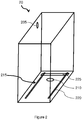
- the piece of furniture 20 roughly comprises six faces, five faces of which are fastened to one another in irremovable manner.
- At least one opening 205 for a heat-transfer fluid, air and immovable fuel supply duct is, for example, an opening positioned on one lateral face among the irremovable faces.
- At least one opening 210 for exhaust duct is, for example, an opening positioned on a lower face among the irremovable faces.
- the support 215 for moving the boiler is, for example, a set of rails 220 or wheels forming at least one axis of displacement for the boiler 10.
- the distance between the rails 220 is adjusted by an adjustment means 225 of the gap between the rails.
- This adjustment means 225 is, for example, a rack on which are positioned two rail supports 220, these rail supports 220 each comprising a means of movement along the rack and a locking means of the positioning of the rail support.
- the moving means is, for example, a toothed wheel configured to move along the rack.
- the positioning step 305 is carried out, for example, by the displacement and the positioning, by a user, of the boiler 10 on a furniture moving support 20, this displacement support having left the cavity formed by the interior. furniture 20.
- the output of the displacement support is achieved by the implementation of a traction of a user on a furniture handle 20 in which the boiler 10 is intended to be recessed.
- the fixing step 310 is carried out, for example, by screwing the boiler 10 to the furniture moving support 20.
- the positioning step 315 of each flexible pipe is carried out, for example, by screwing each flexible pipe, associated with a supply pipe, to an inlet of the boiler 10.
- this positioning step 315 is performed, the boiler 10 is positioned outside the cavity formed by the interior of the cabinet 20.
- the displacement step 320 of the boiler is carried out, for example, by the application of a thrust by the user on the handle of the cabinet 20 or the boiler 10 so as to push the boiler 10 into the cabinet 20.
- the positioning step 325 of the rigid duct is performed, for example, by clipping the rigid duct on the one hand to the irremovable exhaust duct and on the other hand to the boiler outlets.
- the operation step 330 of the boiler is carried out, for example, by the actuation of a switch by a user, this switch allowing the electrical supply of the boiler 10.
- the out of operation step 405 of the boiler 10 is performed, for example, by the actuation of a switch by a user.
- This switch controls, for example, the power supply of the boiler 10.
- the withdrawal step 410 of the duct is performed, for example, by a user dissociating the rigid conduit and removable outputs of the boiler 10 on the one hand and a non-removable evacuation conduit on the other.
- the displacement step 415 is performed, for example, by a user pulling on a handle positioned on one side of the cabinet 20 or the boiler 10 so that the displacement support of the boiler 10 drives the boiler out of the cavity formed by the interior of the cabinet 20.
- each flexible pipe is carried out, for example, by unscrewing each flexible pipe connected to an inlet of the boiler 10.
- the removal step 425 of the fixing means is carried out, for example, by unscrewing the boiler 10 from the displacement support.
- the removal step 430 of the boiler 10 is carried out, for example, by a user moving the boiler 10.
Landscapes
- Engineering & Computer Science (AREA)
- Physics & Mathematics (AREA)
- General Engineering & Computer Science (AREA)
- Chemical & Material Sciences (AREA)
- Combustion & Propulsion (AREA)
- Mechanical Engineering (AREA)
- Thermal Sciences (AREA)
- Computer Networks & Wireless Communication (AREA)
- Computer Hardware Design (AREA)
- Fluid Mechanics (AREA)
- Health & Medical Sciences (AREA)
- Biomedical Technology (AREA)
- Incineration Of Waste (AREA)
- Fluidized-Bed Combustion And Resonant Combustion (AREA)
Claims (14)
- Vorrichtung mit einem Heizkessel (10), in einem Möbel eingebaut, die Folgendes umfasst:- den Heizkessel (10), umfassend:- einen Wärmeträgerfluid-Einlass (105),- einen Brennstoffeinlass (110),- einen Lufteinlass (115),- ein Mittel (120) zur Erwärmung des Wärmeträgerfluids durch Verbrennung des Brennstoffs,- einen Auslass (125) für das beheizte Wärmeträgerfluid,- einen Abgasauslass (125),- ein Mittel (130) zum Befestigen an einem Halter (135) zum Verschieben des Heizkessels entlang einer Achse im Möbel und- einen Griff (140) zum Verschieben des Heizkessels entlang einer Achse zum Verschieben des Verschiebungshalters aus dem Möbel heraus und umgekehrt.- das Möbelstück zum Einbau des Heizkessels, umfassend:- mindestens eine Öffnung (205) für die unlösbare Wärmeträgerfluid-, Luft- und Brennstoffzuleitung, um einen Einlass des Heizkessels mit dem Wärmeträgerfluid und einen Einlass mit dem Brennstoff zu speisen.- mindestens eine Öffnung (210) für die unlösbare Abluftleitung für Verbrennungsprodukte und Kondensate des Wärmeträgerfluids, um die vom Heizkessel erzeugten Verbrennungsprodukte und Kondensate des Wärmeträgerfluids abzuleiten und- einen Halter (215) zum Verschieben des Heizkessels entlang einer Achse, so dass der Heizkessel wechselweise gegenüber der Zuluft- oder Abluftleitung oder zumindest teilweise außerhalb des Möbels positioniert werden kann.
- Vorrichtung nach Anspruch 1, bei dem der Wärmeträgerauslass (125) und der Abgasauslass (125) grob konzentrisch angeordnete Leitungen sind.
- Vorrichtung nach Anspruch 2, bei dem der Heizkessel (10) Folgendes umfasst:- eine starre und lösbare Anschlussleitung (150) zwischen den konzentrischen Auslässen des Heizkessels und eine unlösbare Abfuhrleitung (155) für Verbrennungsgas und Wärmeträgerfluid und- ein Mittel (145) zur Befestigung der starren Leitung (150).
- Vorrichtung nach Anspruch 3, bei dem der Heizkessel (10) Folgendes umfasst:- eine Detektorvorrichtung (160), die dafür ausgelegt ist, einen Verbindungsfehler zwischen der starren und lösbaren Anschlussleitung (150) und den Auslässen (125) des Heizkessels oder der unlösbaren Abfuhrleitung (155) zu erfassen und- eine Sendevorrichtung (165) zum Aussenden eines Signals, das für die Erkennung einer Verbindungsstörung repräsentativ ist.
- Vorrichtung nach Anspruch 4, bei der der Heizkessel (10) ein Mittel (170) zur Öffnung/Schließung von mindestens einem Einlass (105, 110, 115) aufweist, das so konfiguriert ist, dass jeder genannte Einlass geschlossen gehalten wird, sobald eine Verbindungsstörung der Anschlussleitung (150) erkannt wird.
- Vorrichtung nach einem der Ansprüche 4 oder 5, bei der der Heizkessel (10) eine Übertragungsvorrichtung (175) aufweist, die dafür ausgelegt ist, ein drahtloses Signal, das für die Erkennung einer Verbindungsstörung der Anschlussleitung repräsentativ ist, an eine entfernte Zentrale zu übertragen.
- Vorrichtung nach einem der Ansprüche 1 bis 6, bei der die Auslässe (125) auf einem unteren Bereich des Kessels positioniert sind und auf das untere Ende des Kessels ausgerichtet sind.
- Vorrichtung nach einem der Ansprüche 1 bis 7, bei der der Heizkessel (10) mindestens ein flexibles lösbares Rohr (180) zur Befestigung der Einlässe (105, 110, 115) an mindestens einer unlösbaren Fluid- und Brennstoffzuleitung (185) aufweist.
- Vorrichtung nach Anspruch 8, bei dem der Heizkessel (10) Folgendes umfasst:- eine Detektorvorrichtung (160), die dafür ausgelegt ist, einen Verbindungsfehler zwischen einem flexiblen Rohr (180) und den Einlässen (105, 110, 115) des Heizkessels oder den Zuleitungen (185) zu erfassen und- eine Sendevorrichtung (165) zum Aussenden eines Signals, das für die Erkennung einer Verbindungsstörung repräsentativ ist.
- Vorrichtung nach Anspruch 9, bei der der Heizkessel (10) ein Mittel (170) zur Öffnung/Schließung von mindestens einem Einlass (105, 110, 115) aufweist, das so konfiguriert ist, dass jeder genannte Einlass (105, 110, 115) geschlossen gehalten wird, sobald eine Verbindungsstörung des flexiblen Rohrs (180) erkannt wird.
- Vorrichtung nach einem der Ansprüche 9 oder 10, bei der der Heizkessel (10) eine Übertragungsvorrichtung (175) aufweist, die dafür ausgelegt ist, ein drahtloses Signal, das für die Erkennung einer Verbindungsstörung des flexiblen Rohrs repräsentativ ist, an eine entfernte Zentrale- zu übertragen.
- Vorrichtung nach einem der Ansprüche 1 bis 11, bei der der Verschiebungshalter (135) ein Rad (137) ist, das sich an einer Schiene entlang bewegt (139).
- Verfahren (30) zur Installation einer Vorrichtung nach den Ansprüchen 3 und 8, das folgende Schritte umfasst:- einen Schritt (305) der Positionierung des Heizkessels im Möbelstück,- einen Schritt (310) der Befestigung des Mittels zur Befestigung des Heizkessels an einem Verschiebungshalter des Möbels,- einen Schritt (315) der Positionierung von jedem flexiblen Rohr, so dass jeder Einlass des Heizkessels mit einer Zuleitung verbunden ist.- einen Schritt (320) der Verschiebung des Heizkessels entlang einer Achse des Verschiebungshalters des Heizkessels, so dass der Heizkessel in das Möbelstück eingelassen wird.- einen Schritt (325) der Positionierung der starren und lösbaren Anschlussleitung, so dass jeder Auslass des Heizkessels mit einer Abluftleitung verbunden ist und- einen Schritt (330) der Inbetriebnahme des Heizkessels.
- Verfahren (40) zur Wartung einer Vorrichtung nach den Ansprüchen 3 und 8, das folgende Schritte umfasst:- einen Schritt (405) der Außerbetriebnahme des Heizkessels.- einen Schritt (410) der Entfernung der starren und lösbaren Anschlussleitung,- einen Schritt (415) der Verschiebung des Heizkessels entlang einer Achse des Verschiebungshalters des Heizkessels entlang einer Achse, um den Heizkessel zumindest teilweise außerhalb des Möbels zu positionieren.- einen Schritt (420) der Entfernung jedes flexiblen Rohrs,- einen Schritt (425) der Entfernung des Befestigungsmittels am Verschiebungshalter des Möbels und- einen Schritt (430) der Entnahme des Heizkessels aus dem Möbel.
Applications Claiming Priority (1)
| Application Number | Priority Date | Filing Date | Title |
|---|---|---|---|
| FR1455932A FR3022990B1 (fr) | 2014-06-25 | 2014-06-25 | Chaudiere encastrable dans un meuble, meuble pour encastrement d'une chaudiere, procedes d'installation et de maintenance d'une chaudiere |
Publications (2)
| Publication Number | Publication Date |
|---|---|
| EP2960592A1 EP2960592A1 (de) | 2015-12-30 |
| EP2960592B1 true EP2960592B1 (de) | 2018-10-10 |
Family
ID=51726651
Family Applications (1)
| Application Number | Title | Priority Date | Filing Date |
|---|---|---|---|
| EP15173893.7A Not-in-force EP2960592B1 (de) | 2014-06-25 | 2015-06-25 | Dampferzeuger, der in ein möbelstück einbaubar ist, möbelstück für den einbau eines dampferzeugers, einbau- und instandhaltungsverfahren eines dampferzeugers |
Country Status (2)
| Country | Link |
|---|---|
| EP (1) | EP2960592B1 (de) |
| FR (1) | FR3022990B1 (de) |
Family Cites Families (5)
| Publication number | Priority date | Publication date | Assignee | Title |
|---|---|---|---|---|
| FR2120430A5 (de) * | 1970-12-29 | 1972-08-18 | Paillez Clauden | |
| DE4442010A1 (de) * | 1994-11-28 | 1996-05-30 | Lentjes Kraftwerkstechnik | Vorrichtung zur Montage von Kesselteilen |
| CN2477947Y (zh) * | 2001-05-16 | 2002-02-20 | 李国路 | 分体式采暖炊事两用炉 |
| TW201142222A (en) * | 2010-05-21 | 2011-12-01 | Shun-Qi Yang | Power-saving water boiling machine |
| TW201218909A (en) * | 2010-10-29 | 2012-05-01 | Hon Hai Prec Ind Co Ltd | Container data center |
-
2014
- 2014-06-25 FR FR1455932A patent/FR3022990B1/fr not_active Expired - Fee Related
-
2015
- 2015-06-25 EP EP15173893.7A patent/EP2960592B1/de not_active Not-in-force
Non-Patent Citations (1)
| Title |
|---|
| None * |
Also Published As
| Publication number | Publication date |
|---|---|
| EP2960592A1 (de) | 2015-12-30 |
| FR3022990A1 (fr) | 2016-01-01 |
| FR3022990B1 (fr) | 2019-06-14 |
Similar Documents
| Publication | Publication Date | Title |
|---|---|---|
| WO2007136598A3 (en) | Combination conveyor oven | |
| FR3029595A1 (fr) | Systeme antigel pour une canalisation | |
| FR3022990B1 (fr) | Chaudiere encastrable dans un meuble, meuble pour encastrement d'une chaudiere, procedes d'installation et de maintenance d'une chaudiere | |
| FR2942531A1 (fr) | Caisson de distribution d'air. | |
| KR102333176B1 (ko) | 어쿠스틱 수트 블로워 무선 원격 진단시스템 | |
| CN207008839U (zh) | 一种基于物联网的厨房燃气安全系统 | |
| EP1461126B1 (de) | Verfahren und vorrichtung zur entfernung von restwasser | |
| FR2602310A1 (fr) | Dispositif de transmission d'un signal de securite collective pour un reseau d'extraction mecanique d'air et de gaz de combustion d'un ensemble de locaux d'habitation | |
| FR3063799A3 (fr) | Dispositif pour la fixation murale rapide d'un appareil de chauffage d'environnements et d'eau sanitaire | |
| BE1023820B1 (fr) | Dispositif d'installation de chaudière facilitant le remplacement ou la réparation de celle-ci | |
| CN108035410B (zh) | 一种厨房排水管道油污的清除装置 | |
| ATE490435T1 (de) | Vakuumbehälterwandelelement mit einer durchgeführten leitung | |
| EP3023725B1 (de) | Kochgerät, anlage, die diese umfasst, und einbauverfahren einer solchen vorrichtung | |
| RU167941U9 (ru) | Выходной элемент трубопровода в установке пожаротушения | |
| FR3027629A1 (fr) | Systeme de raccordement pour panneau de toit d'une enceinte de protection thermoacoustique, panneau de toit et enceinte thermoacoustique correspondante | |
| CN218272120U (zh) | 一种用于燃气蒸汽模块炉热交换器结水垢的判断检测装置 | |
| EP2117996B1 (de) | Vorrichtung zur erwärmung eines behälters zur lagerung wiederhergestellten lebensmittelöls | |
| EP3981314B1 (de) | Überlaufschutz-abschaltsystem | |
| KR101079821B1 (ko) | 가스 자동 공급차단장치 | |
| CN202056462U (zh) | 用于清洗低焰点物料管道的内堵装置 | |
| GB2577156A (en) | A leak detection system for use with heating apparatus | |
| CN112066423B (zh) | 燃气切断阀与减压阀集成控制装置 | |
| FR2953911A1 (fr) | Dispositif de production d'eau chaude | |
| FR3080910A1 (fr) | Systeme de dosseret pour l'installation d'une chaudiere a gaz a condensation | |
| FR2824627A1 (fr) | Dispositif de production d'eau chaude sanitaire a partir d'un miniballon a maintien electrique et d'une chaudiere mixte a gaz |
Legal Events
| Date | Code | Title | Description |
|---|---|---|---|
| PUAI | Public reference made under article 153(3) epc to a published international application that has entered the european phase |
Free format text: ORIGINAL CODE: 0009012 |
|
| AK | Designated contracting states |
Kind code of ref document: A1 Designated state(s): AL AT BE BG CH CY CZ DE DK EE ES FI FR GB GR HR HU IE IS IT LI LT LU LV MC MK MT NL NO PL PT RO RS SE SI SK SM TR |
|
| AX | Request for extension of the european patent |
Extension state: BA ME |
|
| 17P | Request for examination filed |
Effective date: 20160630 |
|
| RBV | Designated contracting states (corrected) |
Designated state(s): AL AT BE BG CH CY CZ DE DK EE ES FI FR GB GR HR HU IE IS IT LI LT LU LV MC MK MT NL NO PL PT RO RS SE SI SK SM TR |
|
| STAA | Information on the status of an ep patent application or granted ep patent |
Free format text: STATUS: EXAMINATION IS IN PROGRESS |
|
| 17Q | First examination report despatched |
Effective date: 20170331 |
|
| REG | Reference to a national code |
Ref country code: DE Ref legal event code: R079 Ref document number: 602015017735 Country of ref document: DE Free format text: PREVIOUS MAIN CLASS: F24H0001060000 Ipc: A47B0081000000 |
|
| GRAP | Despatch of communication of intention to grant a patent |
Free format text: ORIGINAL CODE: EPIDOSNIGR1 |
|
| STAA | Information on the status of an ep patent application or granted ep patent |
Free format text: STATUS: GRANT OF PATENT IS INTENDED |
|
| RIC1 | Information provided on ipc code assigned before grant |
Ipc: F24H 9/00 20060101ALI20180328BHEP Ipc: F24H 9/02 20060101ALI20180328BHEP Ipc: F24H 9/20 20060101ALI20180328BHEP Ipc: F24H 1/06 20060101ALI20180328BHEP Ipc: F24H 1/18 20060101ALI20180328BHEP Ipc: A47B 81/00 20060101AFI20180328BHEP Ipc: F24H 9/12 20060101ALI20180328BHEP |
|
| INTG | Intention to grant announced |
Effective date: 20180420 |
|
| RIN1 | Information on inventor provided before grant (corrected) |
Inventor name: LE DEAN, PATRICE Inventor name: ROUQUIER, PHILIPPE Inventor name: RUILLARD, ROMAIN Inventor name: PIASCO, JEAN-MARC |
|
| GRAS | Grant fee paid |
Free format text: ORIGINAL CODE: EPIDOSNIGR3 |
|
| GRAA | (expected) grant |
Free format text: ORIGINAL CODE: 0009210 |
|
| STAA | Information on the status of an ep patent application or granted ep patent |
Free format text: STATUS: THE PATENT HAS BEEN GRANTED |
|
| AK | Designated contracting states |
Kind code of ref document: B1 Designated state(s): AL AT BE BG CH CY CZ DE DK EE ES FI FR GB GR HR HU IE IS IT LI LT LU LV MC MK MT NL NO PL PT RO RS SE SI SK SM TR |
|
| REG | Reference to a national code |
Ref country code: GB Ref legal event code: FG4D Free format text: NOT ENGLISH |
|
| REG | Reference to a national code |
Ref country code: CH Ref legal event code: EP Ref country code: AT Ref legal event code: REF Ref document number: 1050225 Country of ref document: AT Kind code of ref document: T Effective date: 20181015 |
|
| REG | Reference to a national code |
Ref country code: IE Ref legal event code: FG4D Free format text: LANGUAGE OF EP DOCUMENT: FRENCH Ref country code: DE Ref legal event code: R096 Ref document number: 602015017735 Country of ref document: DE |
|
| REG | Reference to a national code |
Ref country code: NL Ref legal event code: MP Effective date: 20181010 |
|
| REG | Reference to a national code |
Ref country code: LT Ref legal event code: MG4D |
|
| REG | Reference to a national code |
Ref country code: AT Ref legal event code: MK05 Ref document number: 1050225 Country of ref document: AT Kind code of ref document: T Effective date: 20181010 |
|
| PG25 | Lapsed in a contracting state [announced via postgrant information from national office to epo] |
Ref country code: NL Free format text: LAPSE BECAUSE OF FAILURE TO SUBMIT A TRANSLATION OF THE DESCRIPTION OR TO PAY THE FEE WITHIN THE PRESCRIBED TIME-LIMIT Effective date: 20181010 |
|
| PG25 | Lapsed in a contracting state [announced via postgrant information from national office to epo] |
Ref country code: HR Free format text: LAPSE BECAUSE OF FAILURE TO SUBMIT A TRANSLATION OF THE DESCRIPTION OR TO PAY THE FEE WITHIN THE PRESCRIBED TIME-LIMIT Effective date: 20181010 Ref country code: LT Free format text: LAPSE BECAUSE OF FAILURE TO SUBMIT A TRANSLATION OF THE DESCRIPTION OR TO PAY THE FEE WITHIN THE PRESCRIBED TIME-LIMIT Effective date: 20181010 Ref country code: BG Free format text: LAPSE BECAUSE OF FAILURE TO SUBMIT A TRANSLATION OF THE DESCRIPTION OR TO PAY THE FEE WITHIN THE PRESCRIBED TIME-LIMIT Effective date: 20190110 Ref country code: AT Free format text: LAPSE BECAUSE OF FAILURE TO SUBMIT A TRANSLATION OF THE DESCRIPTION OR TO PAY THE FEE WITHIN THE PRESCRIBED TIME-LIMIT Effective date: 20181010 Ref country code: PL Free format text: LAPSE BECAUSE OF FAILURE TO SUBMIT A TRANSLATION OF THE DESCRIPTION OR TO PAY THE FEE WITHIN THE PRESCRIBED TIME-LIMIT Effective date: 20181010 Ref country code: FI Free format text: LAPSE BECAUSE OF FAILURE TO SUBMIT A TRANSLATION OF THE DESCRIPTION OR TO PAY THE FEE WITHIN THE PRESCRIBED TIME-LIMIT Effective date: 20181010 Ref country code: LV Free format text: LAPSE BECAUSE OF FAILURE TO SUBMIT A TRANSLATION OF THE DESCRIPTION OR TO PAY THE FEE WITHIN THE PRESCRIBED TIME-LIMIT Effective date: 20181010 Ref country code: ES Free format text: LAPSE BECAUSE OF FAILURE TO SUBMIT A TRANSLATION OF THE DESCRIPTION OR TO PAY THE FEE WITHIN THE PRESCRIBED TIME-LIMIT Effective date: 20181010 Ref country code: NO Free format text: LAPSE BECAUSE OF FAILURE TO SUBMIT A TRANSLATION OF THE DESCRIPTION OR TO PAY THE FEE WITHIN THE PRESCRIBED TIME-LIMIT Effective date: 20190110 Ref country code: IS Free format text: LAPSE BECAUSE OF FAILURE TO SUBMIT A TRANSLATION OF THE DESCRIPTION OR TO PAY THE FEE WITHIN THE PRESCRIBED TIME-LIMIT Effective date: 20190210 |
|
| PG25 | Lapsed in a contracting state [announced via postgrant information from national office to epo] |
Ref country code: GR Free format text: LAPSE BECAUSE OF FAILURE TO SUBMIT A TRANSLATION OF THE DESCRIPTION OR TO PAY THE FEE WITHIN THE PRESCRIBED TIME-LIMIT Effective date: 20190111 Ref country code: PT Free format text: LAPSE BECAUSE OF FAILURE TO SUBMIT A TRANSLATION OF THE DESCRIPTION OR TO PAY THE FEE WITHIN THE PRESCRIBED TIME-LIMIT Effective date: 20190210 Ref country code: RS Free format text: LAPSE BECAUSE OF FAILURE TO SUBMIT A TRANSLATION OF THE DESCRIPTION OR TO PAY THE FEE WITHIN THE PRESCRIBED TIME-LIMIT Effective date: 20181010 Ref country code: AL Free format text: LAPSE BECAUSE OF FAILURE TO SUBMIT A TRANSLATION OF THE DESCRIPTION OR TO PAY THE FEE WITHIN THE PRESCRIBED TIME-LIMIT Effective date: 20181010 Ref country code: SE Free format text: LAPSE BECAUSE OF FAILURE TO SUBMIT A TRANSLATION OF THE DESCRIPTION OR TO PAY THE FEE WITHIN THE PRESCRIBED TIME-LIMIT Effective date: 20181010 |
|
| REG | Reference to a national code |
Ref country code: DE Ref legal event code: R097 Ref document number: 602015017735 Country of ref document: DE |
|
| PG25 | Lapsed in a contracting state [announced via postgrant information from national office to epo] |
Ref country code: DK Free format text: LAPSE BECAUSE OF FAILURE TO SUBMIT A TRANSLATION OF THE DESCRIPTION OR TO PAY THE FEE WITHIN THE PRESCRIBED TIME-LIMIT Effective date: 20181010 Ref country code: CZ Free format text: LAPSE BECAUSE OF FAILURE TO SUBMIT A TRANSLATION OF THE DESCRIPTION OR TO PAY THE FEE WITHIN THE PRESCRIBED TIME-LIMIT Effective date: 20181010 Ref country code: IT Free format text: LAPSE BECAUSE OF FAILURE TO SUBMIT A TRANSLATION OF THE DESCRIPTION OR TO PAY THE FEE WITHIN THE PRESCRIBED TIME-LIMIT Effective date: 20181010 |
|
| PLBE | No opposition filed within time limit |
Free format text: ORIGINAL CODE: 0009261 |
|
| STAA | Information on the status of an ep patent application or granted ep patent |
Free format text: STATUS: NO OPPOSITION FILED WITHIN TIME LIMIT |
|
| PG25 | Lapsed in a contracting state [announced via postgrant information from national office to epo] |
Ref country code: SK Free format text: LAPSE BECAUSE OF FAILURE TO SUBMIT A TRANSLATION OF THE DESCRIPTION OR TO PAY THE FEE WITHIN THE PRESCRIBED TIME-LIMIT Effective date: 20181010 Ref country code: EE Free format text: LAPSE BECAUSE OF FAILURE TO SUBMIT A TRANSLATION OF THE DESCRIPTION OR TO PAY THE FEE WITHIN THE PRESCRIBED TIME-LIMIT Effective date: 20181010 Ref country code: SM Free format text: LAPSE BECAUSE OF FAILURE TO SUBMIT A TRANSLATION OF THE DESCRIPTION OR TO PAY THE FEE WITHIN THE PRESCRIBED TIME-LIMIT Effective date: 20181010 Ref country code: RO Free format text: LAPSE BECAUSE OF FAILURE TO SUBMIT A TRANSLATION OF THE DESCRIPTION OR TO PAY THE FEE WITHIN THE PRESCRIBED TIME-LIMIT Effective date: 20181010 |
|
| 26N | No opposition filed |
Effective date: 20190711 |
|
| PG25 | Lapsed in a contracting state [announced via postgrant information from national office to epo] |
Ref country code: SI Free format text: LAPSE BECAUSE OF FAILURE TO SUBMIT A TRANSLATION OF THE DESCRIPTION OR TO PAY THE FEE WITHIN THE PRESCRIBED TIME-LIMIT Effective date: 20181010 |
|
| REG | Reference to a national code |
Ref country code: DE Ref legal event code: R119 Ref document number: 602015017735 Country of ref document: DE |
|
| PG25 | Lapsed in a contracting state [announced via postgrant information from national office to epo] |
Ref country code: MC Free format text: LAPSE BECAUSE OF FAILURE TO SUBMIT A TRANSLATION OF THE DESCRIPTION OR TO PAY THE FEE WITHIN THE PRESCRIBED TIME-LIMIT Effective date: 20181010 |
|
| REG | Reference to a national code |
Ref country code: CH Ref legal event code: PL |
|
| GBPC | Gb: european patent ceased through non-payment of renewal fee |
Effective date: 20190625 |
|
| REG | Reference to a national code |
Ref country code: BE Ref legal event code: MM Effective date: 20190630 |
|
| PG25 | Lapsed in a contracting state [announced via postgrant information from national office to epo] |
Ref country code: TR Free format text: LAPSE BECAUSE OF FAILURE TO SUBMIT A TRANSLATION OF THE DESCRIPTION OR TO PAY THE FEE WITHIN THE PRESCRIBED TIME-LIMIT Effective date: 20181010 |
|
| PG25 | Lapsed in a contracting state [announced via postgrant information from national office to epo] |
Ref country code: IE Free format text: LAPSE BECAUSE OF NON-PAYMENT OF DUE FEES Effective date: 20190625 Ref country code: GB Free format text: LAPSE BECAUSE OF NON-PAYMENT OF DUE FEES Effective date: 20190625 Ref country code: DE Free format text: LAPSE BECAUSE OF NON-PAYMENT OF DUE FEES Effective date: 20200101 |
|
| PG25 | Lapsed in a contracting state [announced via postgrant information from national office to epo] |
Ref country code: LU Free format text: LAPSE BECAUSE OF NON-PAYMENT OF DUE FEES Effective date: 20190625 Ref country code: BE Free format text: LAPSE BECAUSE OF NON-PAYMENT OF DUE FEES Effective date: 20190630 Ref country code: CH Free format text: LAPSE BECAUSE OF NON-PAYMENT OF DUE FEES Effective date: 20190630 Ref country code: LI Free format text: LAPSE BECAUSE OF NON-PAYMENT OF DUE FEES Effective date: 20190630 |
|
| PG25 | Lapsed in a contracting state [announced via postgrant information from national office to epo] |
Ref country code: CY Free format text: LAPSE BECAUSE OF FAILURE TO SUBMIT A TRANSLATION OF THE DESCRIPTION OR TO PAY THE FEE WITHIN THE PRESCRIBED TIME-LIMIT Effective date: 20181010 |
|
| PG25 | Lapsed in a contracting state [announced via postgrant information from national office to epo] |
Ref country code: MT Free format text: LAPSE BECAUSE OF FAILURE TO SUBMIT A TRANSLATION OF THE DESCRIPTION OR TO PAY THE FEE WITHIN THE PRESCRIBED TIME-LIMIT Effective date: 20181010 Ref country code: HU Free format text: LAPSE BECAUSE OF FAILURE TO SUBMIT A TRANSLATION OF THE DESCRIPTION OR TO PAY THE FEE WITHIN THE PRESCRIBED TIME-LIMIT; INVALID AB INITIO Effective date: 20150625 |
|
| PGFP | Annual fee paid to national office [announced via postgrant information from national office to epo] |
Ref country code: FR Payment date: 20210519 Year of fee payment: 7 |
|
| PG25 | Lapsed in a contracting state [announced via postgrant information from national office to epo] |
Ref country code: MK Free format text: LAPSE BECAUSE OF FAILURE TO SUBMIT A TRANSLATION OF THE DESCRIPTION OR TO PAY THE FEE WITHIN THE PRESCRIBED TIME-LIMIT Effective date: 20181010 |
|
| PG25 | Lapsed in a contracting state [announced via postgrant information from national office to epo] |
Ref country code: FR Free format text: LAPSE BECAUSE OF NON-PAYMENT OF DUE FEES Effective date: 20220630 |