EP2960414A1 - Antriebsvorrichtung für eine drehtür - Google Patents
Antriebsvorrichtung für eine drehtür Download PDFInfo
- Publication number
- EP2960414A1 EP2960414A1 EP15173254.2A EP15173254A EP2960414A1 EP 2960414 A1 EP2960414 A1 EP 2960414A1 EP 15173254 A EP15173254 A EP 15173254A EP 2960414 A1 EP2960414 A1 EP 2960414A1
- Authority
- EP
- European Patent Office
- Prior art keywords
- drive
- motor
- spindle
- drive device
- clutch
- Prior art date
- Legal status (The legal status is an assumption and is not a legal conclusion. Google has not performed a legal analysis and makes no representation as to the accuracy of the status listed.)
- Granted
Links
Images

Classifications
-
- E—FIXED CONSTRUCTIONS
- E05—LOCKS; KEYS; WINDOW OR DOOR FITTINGS; SAFES
- E05F—DEVICES FOR MOVING WINGS INTO OPEN OR CLOSED POSITION; CHECKS FOR WINGS; WING FITTINGS NOT OTHERWISE PROVIDED FOR, CONCERNED WITH THE FUNCTIONING OF THE WING
- E05F1/00—Closers or openers for wings, not otherwise provided for in this subclass
- E05F1/08—Closers or openers for wings, not otherwise provided for in this subclass spring-actuated, e.g. for horizontally sliding wings
- E05F1/10—Closers or openers for wings, not otherwise provided for in this subclass spring-actuated, e.g. for horizontally sliding wings for swinging wings, e.g. counterbalance
- E05F1/1041—Closers or openers for wings, not otherwise provided for in this subclass spring-actuated, e.g. for horizontally sliding wings for swinging wings, e.g. counterbalance with a coil spring perpendicular to the pivot axis
- E05F1/105—Closers or openers for wings, not otherwise provided for in this subclass spring-actuated, e.g. for horizontally sliding wings for swinging wings, e.g. counterbalance with a coil spring perpendicular to the pivot axis with a compression spring
-
- E—FIXED CONSTRUCTIONS
- E05—LOCKS; KEYS; WINDOW OR DOOR FITTINGS; SAFES
- E05F—DEVICES FOR MOVING WINGS INTO OPEN OR CLOSED POSITION; CHECKS FOR WINGS; WING FITTINGS NOT OTHERWISE PROVIDED FOR, CONCERNED WITH THE FUNCTIONING OF THE WING
- E05F15/00—Power-operated mechanisms for wings
- E05F15/60—Power-operated mechanisms for wings using electrical actuators
- E05F15/603—Power-operated mechanisms for wings using electrical actuators using rotary electromotors
- E05F15/611—Power-operated mechanisms for wings using electrical actuators using rotary electromotors for swinging wings
- E05F15/616—Power-operated mechanisms for wings using electrical actuators using rotary electromotors for swinging wings operated by push-pull mechanisms
- E05F15/619—Power-operated mechanisms for wings using electrical actuators using rotary electromotors for swinging wings operated by push-pull mechanisms using flexible or rigid rack-and-pinion arrangements
-
- E—FIXED CONSTRUCTIONS
- E05—LOCKS; KEYS; WINDOW OR DOOR FITTINGS; SAFES
- E05F—DEVICES FOR MOVING WINGS INTO OPEN OR CLOSED POSITION; CHECKS FOR WINGS; WING FITTINGS NOT OTHERWISE PROVIDED FOR, CONCERNED WITH THE FUNCTIONING OF THE WING
- E05F15/00—Power-operated mechanisms for wings
- E05F15/60—Power-operated mechanisms for wings using electrical actuators
- E05F15/603—Power-operated mechanisms for wings using electrical actuators using rotary electromotors
- E05F15/611—Power-operated mechanisms for wings using electrical actuators using rotary electromotors for swinging wings
- E05F15/63—Power-operated mechanisms for wings using electrical actuators using rotary electromotors for swinging wings operated by swinging arms
-
- E—FIXED CONSTRUCTIONS
- E05—LOCKS; KEYS; WINDOW OR DOOR FITTINGS; SAFES
- E05F—DEVICES FOR MOVING WINGS INTO OPEN OR CLOSED POSITION; CHECKS FOR WINGS; WING FITTINGS NOT OTHERWISE PROVIDED FOR, CONCERNED WITH THE FUNCTIONING OF THE WING
- E05F3/00—Closers or openers with braking devices, e.g. checks; Construction of pneumatic or liquid braking devices
- E05F3/04—Closers or openers with braking devices, e.g. checks; Construction of pneumatic or liquid braking devices with liquid piston brakes
- E05F3/10—Closers or openers with braking devices, e.g. checks; Construction of pneumatic or liquid braking devices with liquid piston brakes with a spring, other than a torsion spring, and a piston, the axes of which are the same or lie in the same direction
- E05F3/102—Closers or openers with braking devices, e.g. checks; Construction of pneumatic or liquid braking devices with liquid piston brakes with a spring, other than a torsion spring, and a piston, the axes of which are the same or lie in the same direction with rack-and-pinion transmission between driving shaft and piston within the closer housing
-
- E—FIXED CONSTRUCTIONS
- E05—LOCKS; KEYS; WINDOW OR DOOR FITTINGS; SAFES
- E05Y—INDEXING SCHEME ASSOCIATED WITH SUBCLASSES E05D AND E05F, RELATING TO CONSTRUCTION ELEMENTS, ELECTRIC CONTROL, POWER SUPPLY, POWER SIGNAL OR TRANSMISSION, USER INTERFACES, MOUNTING OR COUPLING, DETAILS, ACCESSORIES, AUXILIARY OPERATIONS NOT OTHERWISE PROVIDED FOR, APPLICATION THEREOF
- E05Y2201/00—Constructional elements; Accessories therefor
- E05Y2201/20—Brakes; Disengaging means; Holders; Stops; Valves; Accessories therefor
- E05Y2201/214—Disengaging means
- E05Y2201/216—Clutches
-
- E—FIXED CONSTRUCTIONS
- E05—LOCKS; KEYS; WINDOW OR DOOR FITTINGS; SAFES
- E05Y—INDEXING SCHEME ASSOCIATED WITH SUBCLASSES E05D AND E05F, RELATING TO CONSTRUCTION ELEMENTS, ELECTRIC CONTROL, POWER SUPPLY, POWER SIGNAL OR TRANSMISSION, USER INTERFACES, MOUNTING OR COUPLING, DETAILS, ACCESSORIES, AUXILIARY OPERATIONS NOT OTHERWISE PROVIDED FOR, APPLICATION THEREOF
- E05Y2201/00—Constructional elements; Accessories therefor
- E05Y2201/20—Brakes; Disengaging means; Holders; Stops; Valves; Accessories therefor
- E05Y2201/23—Actuation thereof
- E05Y2201/232—Actuation thereof by automatically acting means
- E05Y2201/234—Actuation thereof by automatically acting means direction dependent
-
- E—FIXED CONSTRUCTIONS
- E05—LOCKS; KEYS; WINDOW OR DOOR FITTINGS; SAFES
- E05Y—INDEXING SCHEME ASSOCIATED WITH SUBCLASSES E05D AND E05F, RELATING TO CONSTRUCTION ELEMENTS, ELECTRIC CONTROL, POWER SUPPLY, POWER SIGNAL OR TRANSMISSION, USER INTERFACES, MOUNTING OR COUPLING, DETAILS, ACCESSORIES, AUXILIARY OPERATIONS NOT OTHERWISE PROVIDED FOR, APPLICATION THEREOF
- E05Y2201/00—Constructional elements; Accessories therefor
- E05Y2201/20—Brakes; Disengaging means; Holders; Stops; Valves; Accessories therefor
- E05Y2201/23—Actuation thereof
- E05Y2201/244—Actuation thereof by manual operation
-
- E—FIXED CONSTRUCTIONS
- E05—LOCKS; KEYS; WINDOW OR DOOR FITTINGS; SAFES
- E05Y—INDEXING SCHEME ASSOCIATED WITH SUBCLASSES E05D AND E05F, RELATING TO CONSTRUCTION ELEMENTS, ELECTRIC CONTROL, POWER SUPPLY, POWER SIGNAL OR TRANSMISSION, USER INTERFACES, MOUNTING OR COUPLING, DETAILS, ACCESSORIES, AUXILIARY OPERATIONS NOT OTHERWISE PROVIDED FOR, APPLICATION THEREOF
- E05Y2201/00—Constructional elements; Accessories therefor
- E05Y2201/20—Brakes; Disengaging means; Holders; Stops; Valves; Accessories therefor
- E05Y2201/252—Type of friction
- E05Y2201/26—Mechanical friction
-
- E—FIXED CONSTRUCTIONS
- E05—LOCKS; KEYS; WINDOW OR DOOR FITTINGS; SAFES
- E05Y—INDEXING SCHEME ASSOCIATED WITH SUBCLASSES E05D AND E05F, RELATING TO CONSTRUCTION ELEMENTS, ELECTRIC CONTROL, POWER SUPPLY, POWER SIGNAL OR TRANSMISSION, USER INTERFACES, MOUNTING OR COUPLING, DETAILS, ACCESSORIES, AUXILIARY OPERATIONS NOT OTHERWISE PROVIDED FOR, APPLICATION THEREOF
- E05Y2201/00—Constructional elements; Accessories therefor
- E05Y2201/60—Suspension or transmission members; Accessories therefor
- E05Y2201/622—Suspension or transmission members elements
- E05Y2201/71—Toothed gearing
- E05Y2201/722—Racks
-
- E—FIXED CONSTRUCTIONS
- E05—LOCKS; KEYS; WINDOW OR DOOR FITTINGS; SAFES
- E05Y—INDEXING SCHEME ASSOCIATED WITH SUBCLASSES E05D AND E05F, RELATING TO CONSTRUCTION ELEMENTS, ELECTRIC CONTROL, POWER SUPPLY, POWER SIGNAL OR TRANSMISSION, USER INTERFACES, MOUNTING OR COUPLING, DETAILS, ACCESSORIES, AUXILIARY OPERATIONS NOT OTHERWISE PROVIDED FOR, APPLICATION THEREOF
- E05Y2400/00—Electronic control; Electrical power; Power supply; Power or signal transmission; User interfaces
- E05Y2400/10—Electronic control
- E05Y2400/30—Electronic control of motors
- E05Y2400/3013—Electronic control of motors during manual wing operation
-
- E—FIXED CONSTRUCTIONS
- E05—LOCKS; KEYS; WINDOW OR DOOR FITTINGS; SAFES
- E05Y—INDEXING SCHEME ASSOCIATED WITH SUBCLASSES E05D AND E05F, RELATING TO CONSTRUCTION ELEMENTS, ELECTRIC CONTROL, POWER SUPPLY, POWER SIGNAL OR TRANSMISSION, USER INTERFACES, MOUNTING OR COUPLING, DETAILS, ACCESSORIES, AUXILIARY OPERATIONS NOT OTHERWISE PROVIDED FOR, APPLICATION THEREOF
- E05Y2900/00—Application of doors, windows, wings or fittings thereof
- E05Y2900/10—Application of doors, windows, wings or fittings thereof for buildings or parts thereof
- E05Y2900/13—Type of wing
- E05Y2900/132—Doors
Definitions
- the invention relates to a drive device for a revolving door specified in the preamble of claim 1. Art.
- Revolving door drives with a motor for door opening and a spring accumulator for door closing are known from the prior art, in which a rigid force or torque transmission takes place. Therefore, when the door is closed manually, the motor must be rotated by the user of the door, i. The swing door drive acts as a pure door closer in this mode. Since the engine is usually preceded by a gear, the remindtreibmoment of the engine has a particularly serious impact. That The desire of the door must compensate for the losses of the engine in addition to the tensioning of the spring accumulator. This requires an increased power requirement and is associated with loss of comfort. Drives with comparatively low power will be difficult to realize, since the engine's torque is constant and this has a strong percentage effect, especially in this area. In addition, compliance with DIN 18263-4 or EN1154, which require 50% efficiency, is difficult or impossible to realize in rigidly connected systems.
- the EP 1 643 065 A2 discloses a door drive for a swing door, which consists of a door frame and hinged to the door frame about a pivot axis hinged door leaf with a drive unit and a power transmission element.
- the drive unit is arranged on the door frame or on the door leaf, and the force transmission element is correspondingly arranged corresponding to the door leaf or on the door frame.
- the drive unit can have a drive spindle as the drive element, which can be driven by means of a drive motor.
- the power transmission element can be designed as a spindle nut, which transmits the opening or closing force to an output shaft.
- the drive unit comprises a slip clutch, which is arranged between the drive motor and the force transmission element that a manual Adjustability of the door leaf is ensured substantially without affecting the drive motor.
- the WO 2011/138420 A1 discloses a rotary vane drive device for driving a rotary vane of a swing door with an electric motor and a gearbox driven by the electric motor whose output member rotatable about a transmission axis is directly connectable to the rotary vane for driving the same.
- the gear ratio device is designed to exercise a slip clutch function.
- the DE 101 48 293 A1 discloses a generic drive device for a revolving door with a motor for door opening and a spring store for door closure.
- the motor acts against a spring force of the spring accumulator, wherein an opening or closing force acts via a drive spindle and a spindle nut on a piston with toothing, which meshes with a rotatably connected to an output shaft pinion.
- the invention has for its object to provide a drive device for a revolving door with a motor for door opening and a spring store for door closure, which allows for a manual walking reduced power consumption and improved comfort.
- Embodiments of the inventive drive device for a revolving door each have a motor for door opening and a spring accumulator for door closure, wherein the motor acts against a spring force of the spring accumulator.
- An opening or closing force acts via a drive spindle and a spindle nut on a piston with toothing, which meshes with a rotatably connected to an output shaft pinion.
- a unilaterally acting coupling is arranged between the motor and the drive spindle, which interrupts a force flow between the motor and the drive spindle when a torque acting in the opening direction is applied to the output shaft. This allows advantageously a slight actuation of the revolving door during manual walking as well as a standard realization possibility for drives with low power. Due to the design of the clutch, the transmittable torque is directly proportional to the set spring force of the spring accumulator or the set door closing torque.
- the basic idea of the invention is based on the unilaterally acting clutch, which is disengaged on application of an additional torque acting in the opening direction on the output shaft, in conjunction with a coupled with the door closer piston screw drive.
- the torque acting in the opening direction is exerted on the output shaft, which is converted in a possible embodiment of the teeth in an axial force which cancels the spring force of the spring accumulator and is transmitted via the drive spindle to the clutch.
- the additional torque applied in the opening direction to the output shaft can advantageously produce an axial force acting on the drive spindle in the clutch which is opposite to the spring force.
- the clutch then disengages and disconnects the engine from the power flow.
- the clutch engages due to the spring force of the spring accumulator and allows a motorized opening or a braked closing of the revolving door.
- the clutch can be engaged and establish the power flow between the motor and the drive spindle when the spring force of the spring accumulator is effective in the clutch.
- the unidirectional clutch may comprise a sleeve freewheel.
- the sleeve freewheel can be carried out in an advantageous manner as an overrunning clutch. This allows a particularly simple and cost-effective implementation of the one-way clutch.
- the torque acting on the output shaft in the opening direction when the revolving door is manually engaged can be transmitted via the toothing and the drive spindle to the sleeve freewheel, which can then perform an overhauling function and separate the power flow between the motor and the drive spindle.
- the sleeve freewheel can perform a holding function, which establish the power flow between the motor and the drive spindle and can allow a motorized opening or a braked closing the revolving door.
- the clutch may comprise a rotatably connected to a drive shaft bell and a screwed onto the drive spindle thrust washer which is rotatably connected to a friction disc.
- the bell can be connected to a rotatably mounted on the drive spindle cover plate.
- the effective spring force of the spring accumulator can produce a frictional engagement between the friction disk and the cover disk via the pressure disk, which can transmit the rotation of the drive shaft to the drive spindle.
- the effective axial force can lift the friction disk over the pressure disk from the cover disk and disconnect or interrupt the power flow between the drive shaft and the drive spindle.
- a transmission can be arranged between the engine and the clutch.
- motors with lower power can be used advantageously.
- the coupling between the motor shaft and the drive spindle is arranged.
- the clutch may be disposed between the transmission shaft and the drive spindle with the transmission shaft coupled to the motor shaft via gears.
- the unidirectional clutch between the engine and the transmission can be arranged.
- the drive spindle can be designed as a ball screw spindle.
- the execution as a ball screw with a ball screw and a ball screw nut ensures advantageously a particularly low-loss force or torque flow.
- a component can perform the function of the spindle nut and the function of the piston with teeth. As a result, the number of parts can be reduced advantageously.
- the spring accumulator may have a helical compression spring.
- the helical compression spring can be arranged concentrically around the drive spindle and be supported at one end to the spindle nut and at the other end to a bearing flange. By this arrangement, a compact design can be achieved in an advantageous manner.
- a drive device 1, 1 A for a revolving door not shown in each case a motor 3 for door opening and a spring 30 for door closing.
- the motor 3 acts against a spring force F F of the spring accumulator 30.
- An opening or closing force generated by the motor 3 or the spring accumulator 30 acts via a drive spindle 38 and a spindle nut 42, 42A on a piston 44, 44A with toothing 46, which meshes with a rotatably connected to an output shaft 49 pinion 48.
- a unilaterally acting coupling 20, 50 is arranged between the motor 3 and the drive spindle 38, which interrupts a force flow between the motor 3 and the drive spindle 38 when a torque acting in the opening direction is applied to the output shaft 49.
- the drive spindle 38 is designed on a motor 3 remote from the end of a ball screw spindle with a ball track 38.3, on which the spindle nut 42 is mounted axially movable.
- the spring accumulator 30 has a arranged in a housing profile 31 helical compression spring 32.
- the helical compression spring 32 is arranged concentrically around the drive spindle 38 and is supported at one end on the spindle nut 42, 42 A and at the other end on a bearing flange 36.
- a thrust bearing 34.2 is arranged on the spindle nut 42, 42A.
- an adjusting element 34.1 is screwed in to support the helical compression spring 32, which enables the adjustment of a bias voltage for the helical compression spring 32.
- Fig. 1 and 2 show the clutch 20 in the engaged state, in which the power flow between the motor 3 and the drive spindle 38 made and in the clutch 20, the spring force F F of the spring accumulator 30 is effective.
- a transmission 10 is arranged with a reduction gear, which comprises a plurality of gears 12, 14, 16.
- the rotation of an axially mounted motor shaft 5 of the motor 3 preferably designed as an electric motor 3 is transmitted via a motor pinion 7 to a first gear 12 of the transmission 10 and via the gears 14, 16 on an axially mounted gear shaft 18.
- the clutch 20 in the illustrated first embodiment a bell 21 which is rotatably connected to the transmission shaft 18, and a pressure plate 24, which is screwed onto a thread 38.2 of the drive spindle 38.
- the thrust washer 24 is supported on a support bush 27, which is pushed onto the drive spindle 38 and in turn is supported on a shoulder 38.1 formed on the drive spindle 38.
- a friction plate 25 is rotatably connected via driving pins 26 with the pressure plate 24.
- the bell 21 is closed at the open end by a cover plate 22 with friction lining, which rotatably connected via driving pins 2 with the bell 21 and rotatably mounted on the circumference of the pushed onto the drive spindle 38 support sleeve 27.
- the effective dashed axial force F a repeals the spring force F F of the spring accumulator 30, so that the effective axial force F a the friction disc 25 lifts over the thrust washer 24 and the support sleeve 27 of the cover plate 22 and the power flow between the transmission shaft 18 and drive spindle 38 separates ,
- the distance between the friction plate 25 and the cover plate 22 in the disengaged state of the clutch 20 substantially corresponds to the gap S.
- the drive spindle 38 is axially supported by the support bushing 27 in the region of the coupling 20 by a rolling bearing.
- a needle bearing 29 is likewise arranged between the housing and the cover disk 22.
- the inventive drive device 1 for a revolving door can be dispensed with the transmission 10 between the engine 3 and the clutch 20, so that the bell 21 is rotatably connected in this embodiment with the motor shaft 5.
- the sleeve freewheel 52 is executed in the illustrated second embodiment as an overrunning clutch and divides the motor shaft 5, wherein the sleeve freewheel 52, the motor shaft 5 coupled to a second part of the motor shaft 5A.
- the motor pinion 7 is arranged at the end of the second part of the motor shaft 5A.
- a shaft and slip clutch 54 is arranged, which advantageously allows an axial tolerance compensation between the motor shaft 5 and the second part of the motor shaft 5A.
- an overload of the motor 3 can be prevented in an advantageous manner.
- the embodiment of the transmission 10 is the same in both embodiments.
- the one-way clutch 20 arranged in the illustrated embodiment between the transmission 10 and the drive spindle 38 in the illustrated second embodiment is replaced by a fixed coupling 20A, which permanently connects the transmission shaft 18 with the drive spindle 38.
- the drive spindle 38 can be coupled, for example via a screwed on the gear end pinion directly with a corresponding toothing in the transmission 10 to produce the adhesion between the motor 3 and drive spindle 38.
- the drive spindle 38 is analogous to the first embodiment at an end remote from the motor 3 designed as a ball screw with a ball track 38.3, on which the spindle nut 42A is mounted axially movable.
- a component 45A performs the function of the spindle nut 42A and the function of the piston 44A with teeth 46.
- This component 45A with the spindle nut 42A and the piston 44A can also be used instead of the spindle nut 42 and the piston 44 in the first embodiment.
- the additional acting in the opening direction torque is exerted on the output shaft 49, which is transmitted via the output pinion 48, the teeth 46 and the drive spindle 38 to the sleeve freewheel 52 and a Matterholfunktion in the sleeve freewheel on manual walking on a not shown door leaf of the revolving door 52 activated.
- the override function separates the power flow between the motor 3 and the drive spindle 38 when the additional torque in the opening direction is applied to the output shaft 49.
- the sleeve freewheel 52 performs a holding function, which establishes the power flow between the motor 3 and the drive spindle 38 and allows a motorized opening or a braked closing of the revolving door.
- invention of the inventive drive device 1 A for a revolving door can be dispensed with the gear 10, so that the second part of the motor shaft 5A is connected directly to the drive spindle 38 in this embodiment.
- the sleeve freewheel 52 can be arranged in an embodiment, not shown, between the transmission 10 and the drive spindle 38, wherein the arrangement between the motor 3 and the transmission 20 is preferable due to the smaller acting moments.
- Embodiments of the drive device for a revolving door according to the invention advantageously allow easy operation of the revolving door during manual walking and a standard realization possibility for low power motors with an efficiency of at least 50%. Due to the design of the clutch, the transmittable torque is directly proportional to the set spring force or the set door closing torque. That is, the desire of the revolving door only has to compensate for the tensioning of the spring accumulator and not the losses due to the engine, so that a reduced expenditure of force is required.
Landscapes
- Power-Operated Mechanisms For Wings (AREA)
- Transmission Devices (AREA)
Abstract
Description
- Die Erfindung betrifft eine Antriebsvorrichtung für eine Drehtür der im Oberbegriff von Patentanspruch 1 angegebenen Art.
- Aus dem Stand der Technik sind Drehtürantriebe mit einem Motor zur Türöffnung und einem Federspeicher zur Türschließung bekannt, bei welchen eine starre Kraft- bzw. Momentenübertragung stattfindet. Daher muss beim manuellen Begehen der Tür der Motor vom Begeher der Tür mitgedreht werden, d.h. der Drehtürantrieb fungiert in dieser Betriebsart als reiner Türschließer. Da dem Motor in der Regel ein Getriebe vorgeschaltet ist, wirkt sich das Rücktreibmoment des Motors besonders gravierend aus. D.h. der Begeher der Tür muss neben dem Spannen des Federspeichers auch die Verluste durch den Motor kompensieren. Dies erfordert einen erhöhten Kraftbedarf und ist mit Komforteinbußen verbunden. Antriebe mit vergleichsweise geringer Leistung werden schwer realisierbar, da das Rücktreibmoment des Motors konstant ist und dies sich gerade in diesem Bereich prozentual stark auswirkt. Zudem ist die Einhaltung von DIN 18263-4 bzw. EN1154, welche 50% Wirkungsgrad fordern, bei starr verbundenen Systemen nur schwer oder gar nicht zu realisieren.
- Die
EP 1 643 065 A2 offenbart einen Türantrieb für eine Drehflügeltür, welche aus einer Türzarge und einem an der Türzarge um eine Schwenkachse schwenkbar angelenktem Türblatt mit einer Antriebseinheit und einem Kraftübertragungselement besteht. Hierbei ist die Antriebseinheit an der Türzarge oder am Türblatt angeordnet, und das Kraftübertragungselement ist entsprechend korrespondierend am Türblatt oder an der Türzarge angeordnet. Die Antriebseinheit kann als Antriebselement eine Antriebsspindel aufweisen, die mittels eines Antriebsmotors antreibbar ist. Das Kraftübertragungselement kann als Spindelmutter ausgeführt werden, welche die Öffnungs- oder Schließkraft auf eine Abtriebswelle überträgt. Zudem umfasst die Antriebseinheit eine Rutschkupplung, welche so zwischen dem Antriebsmotor und dem Kraftübertragungselement angeordnet ist, dass eine manuelle Verstellbarkeit des Türblatts im Wesentlichen ohne Rückwirkung auf den Antriebsmotor gewährleistet ist. - Die
WO 2011/138420 A1 offenbart eine Drehflügelantriebsvorrichtung zum Antreiben eines Drehflügels einer Drehflügeltür mit einem Elektromotor und einer durch den Elektromotor antreibbaren Getriebeübersetzungseinrichtung, deren um eine Getriebeachse drehbares Abtriebsglied direkt an den Drehflügel zum Antreiben desselben anschließbar ist. Hierbei ist die Getriebeübersetzungseinrichtung zum Ausüben einer Rutschkupplungsfunktion ausgebildet. - Die
DE 101 48 293 A1 offenbart eine gattungsgemäße Antriebsvorrichtung für eine Drehtür mit einem Motor zur Türöffnung und einem Federspeicher zur Türschließung. Der Motor wirkt gegen eine Federkraft des Federspeichers, wobei eine Öffnungs- oder Schließkraft über eine Antriebsspindel und eine Spindelmutter auf einen Kolben mit Verzahnung wirkt, welche ein drehfest mit einer Abtriebswelle verbundenes Ritzel kämmt. - Der Erfindung liegt die Aufgabe zugrunde, eine Antriebsvorrichtung für eine Drehtür mit einem Motor zur Türöffnung und einem Federspeicher zur Türschließung anzugeben, welche bei einem manuellen Begehen einen reduzierten Kraftbedarf und einen verbesserten Komfort ermöglicht.
- Diese Aufgabe wird durch die Merkmale der Antriebsvorrichtung für eine Drehtür nach Patentanspruch 1 gelöst.
- Vorteilhafte Ausgestaltungen und Weiterbildungen der Erfindung sind in den abhängigen Ansprüchen angegeben.
- Ausführungsformen der erfindungsgemäßen Antriebsvorrichtung für eine Drehtür weisen jeweils einen Motor zur Türöffnung und einen Federspeicher zur Türschließung auf, wobei der Motor gegen eine Federkraft des Federspeichers wirkt. Eine Öffnungs- oder Schließkraft wirkt über eine Antriebsspindel und eine Spindelmutter auf einen Kolben mit Verzahnung, welche ein drehfest mit einer Abtriebswelle verbundenes Ritzel kämmt. Erfindungsgemäß ist zwischen dem Motor und der Antriebsspindel eine einseitig wirkende Kupplung angeordnet, welche einen Kraftfluss zwischen dem Motor und der Antriebsspindel unterbricht, wenn an der Abtriebswelle ein in Öffnungsrichtung wirkendes Drehmoment anliegt. Dies ermöglicht in vorteilhafter Weise ein leichtes Betätigen der Drehtür beim manuellen Begehen sowie eine normgerechte Realisierungsmöglichkeit für Antriebe mit kleiner Leistung. Durch die Gestaltung der Kupplung ist das übertragbare Moment direkt proportional zur eingestellten Federkraft des Federspeichers bzw. zum eingestellten Türschließmoment.
- Die Grundidee der Erfindung beruht auf der einseitig wirkenden Kupplung, welche bei Anliegen eines zusätzlichen in Öffnungsrichtung wirkenden Drehmoments an der Abtriebswelle ausgerückt wird, in Verbindung mit einem mit dem Türschließerkolben gekoppelten Gewindetrieb. Dadurch wird beim manuellen Begehen der Drehtür das in Öffnungsrichtung wirkende Drehmoment auf die Abtriebswelle ausgeübt, welches in einer möglichen Ausführungsform über die Verzahnung in eine Axialkraft umgewandelt wird, welche die Federkraft des Federspeichers aufhebt und über die Antriebsspindel an die Kupplung übertragen wird. Das bedeutet, dass das in Öffnungsrichtung an der Abtriebswelle anliegende zusätzliche Drehmoment in vorteilhafter Weise eine in der Kupplung wirksame Axialkraft an der Antriebsspindel erzeugen kann, welche der Federkraft entgegengesetzt ist. Die Kupplung rückt dann aus und trennt den Motor vom Kraftfluss ab. Sobald kein Moment mehr in Öffnungsrichtung anliegt, rückt die Kupplung aufgrund der wirkenden Federkraft des Federspeichers ein und erlaubt ein motorisches Öffnen bzw. ein gebremstes Schließen der Drehtür. Das bedeutet, dass die Kupplung eingerückt werden und den Kraftfluss zwischen dem Motor und der Antriebsspindel herstellen kann, wenn in der Kupplung die Federkraft des Federspeichers wirksam ist. Bei einer alternativen Ausführungsform kann die einseitig wirkende Kupplung einen Hülsenfreilauf umfassen. Der Hülsenfreilauf kann in vorteilhafter Weise als Überholkupplung ausgeführt werden. Dies ermöglicht eine besonders einfache und kostengünstige Umsetzung der einseitig wirkenden Kupplung. Das beim manuellen Begehen der Drehtür in Öffnungsrichtung wirkende Drehmoment an der Abtriebswelle kann über die Verzahnung und die Antriebsspindel an den Hülsenfreilauf übertragen werden, welcher dann eine Überholfunktion ausführen und den Kraftfluss zwischen dem Motor und der Antriebsspindel trennen kann. Sobald kein Moment mehr in Öffnungsrichtung anliegt, kann der Hülsenfreilauf eine Haltefunktion ausführen, welche den Kraftfluss zwischen dem Motor und der Antriebsspindel herstellen und ein motorisches Öffnen bzw. ein gebremstes Schließen der Drehtür erlauben kann.
- In vorteilhafter Ausgestaltung der erfindungsgemäßen Antriebsvorrichtung für eine Drehtür kann die Kupplung eine drehfest mit einer Antriebswelle verbundene Glocke und eine auf die Antriebsspindel aufgeschraubte Druckscheibe umfassen, welche drehfest mit einer Reibscheibe verbunden ist. Zudem kann die Glocke mit einer drehbeweglich an der Antriebsspindel gelagerten Deckelscheibe verbunden werden. Die wirksame Federkraft des Federspeichers kann über die Druckscheibe einen Reibschluss zwischen der Reibscheibe und der Deckelscheibe herstellen, welcher die Rotation der Antriebswelle auf die Antriebsspindel übertragen kann. Die wirksame Axialkraft kann hingegen die Reibscheibe über die Druckscheibe von der Deckelscheibe abheben und den Kraftfluss zwischen Antriebswelle und Antriebsspindel trennen bzw. unterbrechen.
- In weiterer vorteilhafter Ausgestaltung der erfindungsgemäßen Antriebsvorrichtung für eine Drehtür kann zwischen dem Motor und der Kupplung ein Getriebe angeordnet werden. Dadurch können in vorteilhafter Weise Motoren mit geringerer Leistung eingesetzt werden. Bei einer Ausführung ohne Getriebe, ist die Kupplung zwischen der Motorwelle und der Antriebsspindel angeordnet. Bei einer Ausführung mit Getriebe, kann die Kupplung zwischen der Getriebewelle und der Antriebsspindel angeordnet werden, wobei die Getriebewelle über Zahnräder mit der Motorwelle gekoppelt ist. Alternativ kann die einseitig wirkende Kupplung zwischen dem Motor und dem Getriebe angeordnet werden.
- In weiterer vorteilhafter Ausgestaltung der erfindungsgemäßen Antriebsvorrichtung für eine Drehtür kann die Antriebsspindel als Kugelgewindespindel ausgeführt werden. Die Ausführung als Kugelgewindetrieb mit einer Kugelspindel und einer Kugelspindelmutter gewährleistet in vorteilhafter Weise einen besonders verlustarmen Kraft- bzw. Momentenfluss. Des Weiteren kann ein Bauteil die Funktion der Spindelmutter und die Funktion des Kolbens mit Verzahnung ausführen. Dadurch kann in vorteilhafter Weise die Teilezahl gesenkt werden.
- In weiterer vorteilhafter Ausgestaltung der erfindungsgemäßen Antriebsvorrichtung für eine Drehtür kann der Federspeicher eine Schraubendruckfeder aufweisen. Dies ermöglicht eine einfache und kostengünstige Realisierung des Federspeichers. Zudem kann die Schraubendruckfeder konzentrisch um die Antriebsspindel angeordnet werden und sich an einem Ende an der Spindelmutter und am anderen Ende an einem Lagerflansch abstützen. Durch diese Anordnung kann in vorteilhafter Weise eine kompakte Bauform erreicht werden.
- Nachfolgend werden Ausführungsbeispiele der Erfindung anhand von zeichnerischen Darstellungen näher erläutert. In den Zeichnungen bezeichnen gleiche Bezugszeichen Komponenten bzw. Elemente, die gleiche bzw. analoge Funktionen ausführen.
- Dabei zeigen:
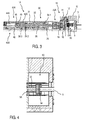
- Fig. 1
- eine Schnittdarstellung eines ersten Ausführungsbeispiels einer erfindungsgemäßen Antriebsvorrichtung für eine Drehtür,
- Fig. 2
- eine Detaildarstellung einer Kupplung der erfindungsgemäßen Antriebsvorrichtung für eine Drehtür aus
Fig. 1 , - Fig. 3
- eine Schnittdarstellung eines zweiten Ausführungsbeispiels einer erfindungsgemäßen Antriebsvorrichtung für eine Drehtür, und
- Fig. 2
- eine Detaildarstellung einer Kupplung der erfindungsgemäßen Antriebsvorrichtung für eine Drehtür aus
Fig. 3 . - Wie aus
Fig. 1 bis 4 ersichtlich ist, umfassen die dargestellten Ausführungsbeispiele einer Antriebsvorrichtung 1, 1 A für eine nicht näher dargestellte Drehtür jeweils einen Motor 3 zur Türöffnung und einen Federspeicher 30 zur Türschließung. Hierbei wirkt der Motor 3 während des Öffnungsvorgangs gegen eine Federkraft FF des Federspeichers 30. Eine über den Motor 3 oder den Federspeicher 30 erzeugte Öffnungs- oder Schließkraft wirkt über eine Antriebsspindel 38 und eine Spindelmutter 42, 42A auf einen Kolben 44, 44A mit Verzahnung 46, welche ein drehfest mit einer Abtriebswelle 49 verbundenes Ritzel 48 kämmt. Erfindungsgemäß ist zwischen dem Motor 3 und der Antriebsspindel 38 eine einseitig wirkende Kupplung 20, 50 angeordnet, welche einen Kraftfluss zwischen dem Motor 3 und der Antriebsspindel 38 unterbricht, wenn an der Abtriebswelle 49 ein in Öffnungsrichtung wirkendes Drehmoment anliegt. - Das bedeutet, dass das Ritzel 48 und die Verzahnung 46 einen Bewegungswandler 40, 40A ausbilden, welcher die durch den Motor 3 oder den Federspeicher 30 über die Antriebsspindel 38 und die Spindelmutter 42, 42A bewirkte translatorische Bewegung des Kolbens 44, 44A mit der Verzahnung 36 in eine Drehbewegung des Ritzels 48 mit der Abtriebswelle 49 umwandelt, um die Drehtür zu öffnen bzw. zu schließen.
- Wie aus
Fig. 1 und 2 weiter ersichtlich ist, wird bei dem dargestellten ersten Ausführungsbeispiel einer erfindungsgemäßen Antriebsvorrichtung 1 für eine Drehtür beim manuellen Begehen über ein nicht dargestelltes Türblatt der Drehtür das zusätzliche in Öffnungsrichtung wirkende Drehmoment auf die Abtriebswelle 49 ausgeübt, welches über das Ritzel 48 und die Verzahnung 46 in eine Axialkraft Fa umgewandelt und über die Spindelmutter 42 und die Antriebsspindel 38 an die Kupplung 20 übertragen wird. Das bedeutet, dass das zusätzliche Drehmoment an der Abtriebswelle 49 die in der Kupplung 20 wirksame Axialkraft Fa an der Antriebsspindel 38 erzeugt, welche der Federkraft FF des Federspeichers 30 entgegengesetzt ist. Um in beide Richtungen eine möglichst verlustfreie Momentenübertragung zu ermöglichen, ist die Antriebsspindel 38 an einem dem Motor 3 abgewandten Ende als Kugelgewindespindel mit einer Kugelbahn 38.3 ausgeführt, auf welcher die Spindelmutter 42 axial beweglich gelagert ist. - Wie aus
Fig. 1 und3 weiter ersichtlich ist, weist der Federspeicher 30 eine in einem Gehäuseprofil 31 angeordnete Schraubendruckfeder 32 auf. Im dargestellten Ausführungsbeispiel ist die Schraubendruckfeder 32 konzentrisch um die Antriebsspindel 38 angeordnet und stützt sich an einem Ende an der Spindelmutter 42, 42A und am anderen Ende an einem Lagerflansch 36 ab. Zur Abstützung der Schraubendruckfeder 32 ist an der Spindelmutter 42, 42A ein Axiallager 34.2 angeordnet. Am Lagerflansch 36 ist zur Abstützung der Schraubendruckfeder 32 ein Einstellelement 34.1 eingeschraubt, welches die Einstellung einer Vorspannung für die Schraubendruckfeder 32 ermöglicht. -
Fig. 1 und 2 zeigen die Kupplung 20 im eingerückten Zustand, in welchem der Kraftfluss zwischen dem Motor 3 und der Antriebsspindel 38 hergestellt und in der Kupplung 20 die Federkraft FF des Federspeichers 30 wirksam ist. Zudem ist im dargestellten ersten Ausführungsbeispiel zwischen dem Motor 3 und der Kupplung 20 ein Getriebe 10 mit einer Untersetzungsverzahnung angeordnet, welche mehrere Zahnräder 12, 14, 16 umfasst. Die Rotation einer axial gelagerten Motorwelle 5 des vorzugweise als Elektromotor ausgeführten Motors 3 wird über ein Motorritzel 7 auf ein erstes Zahnrad 12 des Getriebes 10 und über die Zahnräder 14, 16 auf eine axial gelagerte Getriebewelle 18 übertragen. - Wie insbesondere aus
Fig. 2 weiter ersichtlich ist, weist die Kupplung 20 im dargestellten ersten Ausführungsbeispiel eine Glocke 21, welche drehfest mit der Getriebewelle 18 verbunden ist, und eine Druckscheibe 24 auf, welche auf eine Gewinde 38.2 der Antriebsspindel 38 aufgeschraubt ist. Im aufgeschraubten Zustand stützt sich die Druckscheibe 24 auf einer Stützbuchse 27 ab, welche auf die Antriebsspindel 38 aufgeschoben ist und sich wiederum an einem an der Antriebsspindel 38 ausgebildeten Absatz 38.1 abstützt. Eine Reibscheibe 25 ist über Mitnahmestifte 26 drehfest mit der Druckscheibe 24 verbunden. Zudem ist die Glocke 21 am offenen Ende von einer Deckelscheibe 22 mit Reibbelag abgeschlossen, welche über Mitnahmestifte 2 drehfest mit der Glocke 21 verbunden und drehbeweglich am Umfang der auf die Antriebsspindel 38 aufgeschobenen Stützbuchse 27 gelagert ist. - Wie aus
Fig. 2 weiter ersichtlich ist, stellt die in der Darstellung wirksame Federkraft FF des Federspeichers 30 über die Druckscheibe 24 einen Reibschluss zwischen der Reibscheibe 25 und dem Reibbelag der Deckelscheibe 22 her, welcher die Rotation der Getriebewelle 18 auf die Antriebsspindel 38 überträgt. Beim manuellen Begehen wird das zusätzliche Drehmoment in Öffnungsrichtung auf die Abtriebswelle 49 ausgeübt, welches über das Ritzel 48 und die Verzahnung 46 in eine Axialkraft Fa umgewandelt und über die Spindelmutter 42 und die Antriebsspindel 38 an die Kupplung 20 übertragen wird. Die wirksame gestrichelt dargestellte Axialkraft Fa hebt die Federkraft FF des Federspeichers 30 auf, so dass die wirksame Axialkraft Fa die Reibscheibe 25 über die Druckscheibe 24 und die Stützbuchse 27 von der Deckelscheibe 22 abhebt und den Kraftfluss zwischen Getriebewelle 18 und Antriebsspindel 38 trennt. Das bedeutet, dass die Kupplung 20 ausrückt und ein im eingerückten Zustand der Kupplung 20 vorhandener Spalt S zwischen einem scheibenförmigen Fortsatz der Stützbuchse 27 und einem an einem Gehäuse geführten Nadellager 29 geschlossen wird. Somit entspricht der Abstand zwischen der Reibscheibe 25 und der Deckelscheibe 22 im ausgerückten Zustand der Kupplung 20 im Wesentlichen dem Spalt S. - Wie aus
Fig. 1 und 2 weiter ersichtlich ist, ist die Antriebsspindel 38 über die Stützbuchse 27 im Bereich der Kupplung 20 durch ein Wälzlager axial gelagert. Zur weiteren Reduzierung der Reibungsverluste ist zwischen dem Gehäuse und der Deckelscheibe 22 ebenfalls ein Nadellager 29 angeordnet. Sobald kein Moment mehr in Öffnungsrichtung an der Abtriebswelle 49 anliegt und somit wieder die Federkraft FF in der Kupplung 20 wirkt, rückt die Kupplung 20 ein und erlaubt ein motorisches Öffnen bzw. ein gebremstes Schließen der Drehtür. - Bei einem alternativen nicht dargestellten Ausführungsbeispiel der erfindungsgemäßen Antriebsvorrichtung 1 für eine Drehtür kann auf das Getriebe 10 zwischen dem Motor 3 und der Kupplung 20 verzichtet werden, so dass die Glocke 21 bei diesem Ausführungsbeispiel drehfest mit der Motorwelle 5 verbunden ist.
- Wie aus
Fig. 3 und 4 weiter ersichtlich ist, umfasst die einseitig wirkende Kupplung 50 bei dem dargestellten zweiten Ausführungsbeispiel einer erfindungsgemäßen Antriebsvorrichtung 1 A für eine Drehtür einen Hülsenfreilauf 52. Der Hülsenfreilauf 52 ist im dargestellten zweiten Ausführungsbeispiel als Überholkupplung ausgeführt und teilt die Motorwelle 5, wobei der Hülsenfreilauf 52 die Motorwelle 5 mit einem zweiten Teil der Motorwelle 5A koppelt. Im Unterschied zum ersten Ausführungsbeispiel ist das Motorritzel 7 am Ende des zweiten Teils der Motorwelle 5A angeordnet. Zudem ist zwischen der Motorwelle 5 und dem zweiten Teil der Motorwelle 5A eine Wellen- und Rutschkupplung 54 angeordnet, welche in vorteilhafter Weise einen axialen Toleranzausgleich zwischen der Motorwelle 5 und dem zweiten Teil der Motorwelle 5A ermöglicht. Außerdem kann mittels der Rutschkupplungsfunktion eine Überlastung des Motors 3 in vorteilhafter Weise verhindert werden. - Die Ausführung des Getriebes 10 ist in beiden Ausführungsbeispielen gleich. Zudem ist die im ersten Ausführungsbeispiel zwischen dem Getriebe 10 und der Antriebsspindel 38 angeordnete einseitig wirkende Kupplung 20 im dargestellten zweiten Ausführungsbeispiel durch eine Festkupplung 20A ersetzt, welche die Getriebewelle 18 dauerhaft mit der Antriebsspindel 38 verbindet.
- Bei einer alternativen nicht dargestellten Ausführungsform mit einem Hülsenfreilauf 52, kann die Antriebsspindel 38 beispielsweise über ein am getriebeseitigen Ende aufgeschraubtes Ritzel direkt mit einer entsprechenden Verzahnung im Getriebe 10 gekoppelt werden, um den Kraftschluss zwischen Motor 3 und Antriebsspindel 38 herzustellen. Um in beide Richtungen eine möglichst verlustfreie Momentenübertragung zu ermöglichen, ist die Antriebsspindel 38 analog zum ersten Ausführungsbeispiel an einem dem Motor 3 abgewandten Ende als Kugelgewindespindel mit einer Kugelbahn 38.3 ausgeführt, auf welcher die Spindelmutter 42A axial beweglich gelagert ist. Im Unterschied zum ersten Ausführungsbeispiel führt ein Bauteil 45A die Funktion der Spindelmutter 42A und die Funktion des Kolbens 44A mit Verzahnung 46 aus. Dieses Bauteil 45A mit der Spindelmutter 42A und dem Kolben 44A kann auch im ersten Ausführungsbeispiel anstelle der Spindelmutter 42 und des Kolbens 44 eingesetzt werden.
- In dem in
Fig. 3 und 4 dargestellten zweiten Ausführungsbeispiel wird beim manuellen Begehen über ein nicht dargestelltes Türblatt der Drehtür das zusätzliche in Öffnungsrichtung wirkende Drehmoment auf die Abtriebswelle 49 ausgeübt, welches über das Abtriebsritzel 48, die Verzahnung 46 und die Antriebsspindel 38 an den Hülsenfreilauf 52 übertragen wird und eine Überholfunktion im Hülsenfreilauf 52 aktiviert. Die Überholfunktion trennt den Kraftfluss zwischen dem Motor 3 und der Antriebsspindel 38, wenn an der Abtriebswelle 49 das zusätzliche Drehmoment in Öffnungsrichtung anliegt. Sobald kein Moment mehr in Öffnungsrichtung anliegt, führt der Hülsenfreilauf 52 eine Haltefunktion aus, welche den Kraftfluss zwischen dem Motor 3 und der Antriebsspindel 38 herstellt und ein motorisches Öffnen bzw. ein gebremstes Schließen der Drehtür erlaubt. - Bei einem alternativen nicht dargestellten Ausführungsbeispiel der erfindungsgemäßen Antriebsvorrichtung 1 A für eine Drehtür kann auf das Getriebe 10 verzichtet werden, so dass der zweite Teil der Motorwelle 5A bei diesem Ausführungsbeispiel direkt mit der Antriebsspindel 38 verbunden ist. Zudem kann der Hülsenfreilauf 52 bei einem nicht dargestellten Ausführungsbeispiel auch zwischen dem Getriebe 10 und der Antriebsspindel 38 angeordnet werden, wobei die Anordnung zwischen dem Motor 3 und dem Getriebe 20 aufgrund der kleineren wirkenden Momente vorzuziehen ist.
- Ausführungsformen der erfindungsgemäßen Antriebsvorrichtung für eine Drehtür ermöglichen in vorteilhafter Weise ein leichtes Betätigen der Drehtür beim manuellen Begehen und eine normgerechte Realisierungsmöglichkeit für Motoren mit kleiner Leistung mit einem Wirkungsgrad von mindestens 50%. Durch die Gestaltung der Kupplung ist das übertragbare Moment direkt proportional der eingestellten Federkraft bzw. dem eingestellten Türschließmoment. D.h. der Begeher der Drehtür muss nur das Spannen des Federspeichers und nicht die Verluste durch den Motor kompensieren, so dass ein reduzierter Kraftaufwand erforderlich ist.
-
- 1, 1A
- Antriebsvorrichtung für eine Drehtür
- 3
- Motor
- 5,5A
- Motorwelle
- 7
- Motorritzel
- 10
- Getriebe
- 12, 14, 16
- Zahnrad
- 18
- Getriebewelle
- 20, 50
- einseitig wirkende Kupplung
- 20A
- Festkupplung
- 21
- Glocke
- 22
- Deckelscheibe mit Reibbelag
- 23
- Mitnahmestift
- 24
- Druckscheibe
- 25
- Reibscheibe
- 26
- Mitnahmestift
- 27
- Stützbuchse
- 28
- Wälzlager
- 29
- Nadellager
- 30
- Federspeicher
- 31
- Gehäuseprofil
- 32
- Spiralfeder
- 34.1
- Einstellelement (Federvorspannung)
- 34.2
- Axiallager (Federabstützung)
- 36
- Lagerflansch
- 38
- Antriebsspindel
- 38.1
- Absatz
- 38.2
- Gewinde
- 38.3
- Kugelbahn
- 40,40A
- Bewegungswandler
- 42, 42A
- Spindelmutter
- 44, 44A
- Kolben
- 45A
- Bauteil
- 46
- Verzahnung
- 48
- Abtriebsritzel
- 49
- Abtriebswelle
- 52
- Hülsenfreilauf
- 54
- Wellen- und Rutschkupplung
- S
- Spalt
- FF
- Federkraft
- Fa
- Axialkraft
Claims (14)
- Antriebsvorrichtung (1, 1 A) für eine Drehtür mit einem Motor (3) zur Türöffnung und einem Federspeicher (30) zur Türschließung, wobei der Motor (3) gegen eine Federkraft (FF) des Federspeichers (30) wirkt, wobei eine Öffnungs- oder Schließkraft über eine Antriebsspindel (38) und eine Spindelmutter (42, 42A) auf einen Kolben (44, 44A) mit Verzahnung (46) wirkt, welche ein drehfest mit einer Abtriebswelle (49) verbundenes Ritzel (48) kämmt,
dadurch gekennzeichnet,
dass zwischen dem Motor (3) und der Antriebsspindel (38) eine einseitig wirkende Kupplung (20, 50) angeordnet ist, welche einen Kraftfluss zwischen dem Motor (3) und der Antriebsspindel (38) unterbricht, wenn an der Abtriebswelle (49) ein in Öffnungsrichtung wirkendes zusätzliches Drehmoment anliegt. - Antriebsvorrichtung nach Anspruch 1,
dadurch gekennzeichnet,
dass das in Öffnungsrichtung an der Abtriebswelle (49) anliegende zusätzliche Drehmoment eine in der Kupplung (20) wirksame Axialkraft (Fa) an der Antriebsspindel (38) erzeugt, welche der Federkraft (FF) entgegengesetzt ist. - Antriebsvorrichtung nach Anspruch 2,
dadurch gekennzeichnet,
dass die Kupplung (20) eingerückt ist und den Kraftfluss zwischen dem Motor (3) und der Antriebsspindel (38) herstellt, wenn in der Kupplung (20) die Federkraft (FF) des Federspeichers (30) wirksam ist. - Antriebsvorrichtung nach Anspruch 2 oder 3,
dadurch gekennzeichnet,
dass die Kupplung (20) eine drehfest mit einer Antriebswelle (18) verbundene Glocke (21) und eine auf die Antriebsspindel (38) aufgeschraubte Druckscheibe (24) umfasst, welche drehfest mit einer Reibscheibe (25) verbunden ist, wobei die Glocke (21) mit einer drehbeweglich an der Antriebsspindel (38) gelagerte Deckelscheibe (22) verbunden ist. - Antriebsvorrichtung nach Anspruch 4,
dadurch gekennzeichnet,
dass die wirksame Federkraft (FF) des Federspeichers (30) über die Druckscheibe (24) einen Reibschluss zwischen der Reibscheibe (25) und der Deckelscheibe (22) herstellt, welcher die Rotation der Antriebswelle (18) auf die Antriebsspindel (38) überträgt. - Antriebsvorrichtung nach Anspruch 4 oder 5,
dadurch gekennzeichnet,
dass die wirksame Axialkraft (Fa) die Reibscheibe (25) über die Druckscheibe (24) von der Deckelscheibe (22) abhebt und den Kraftfluss zwischen Antriebswelle (18) und Antriebsspindel (38) trennt. - Antriebsvorrichtung nach einem der Ansprüche 1 bis 6,
dadurch gekennzeichnet,
dass zwischen dem Motor (3) und der Kupplung (20, 50) ein Getriebe (10) angeordnet ist. - Antriebsvorrichtung nach Anspruch 7,
dadurch gekennzeichnet,
dass die Antriebswelle eine Getriebewelle (18) oder eine Motorwelle (5) repräsentiert. - Antriebsvorrichtung nach Anspruch 1,
dadurch gekennzeichnet,
dass die einseitig wirkende Kupplung (50) einen Hülsenfreilauf (52) umfasst. - Antriebsvorrichtung nach Anspruch 9,
dadurch gekennzeichnet,
dass der Hülsenfreilauf (52) als Überholkupplung ausgeführt ist, welche eine Überholfunktion ausführt und den Kraftfluss zwischen dem Motor (3) und der Antriebsspindel (38) trennt, wenn an der Abtriebswelle (49) das zusätzliche Drehmoment in Öffnungsrichtung anliegt, und sonst eine Haltefunktion ausführt, welche den Kraftfluss zwischen dem Motor (3) und der Antriebsspindel (38) herstellt. - Antriebsvorrichtung nach einem der Ansprüche 1 bis 10,
dadurch gekennzeichnet,
dass die Antriebsspindel (38) als Kugelgewindespindel ausgeführt ist. - Antriebsvorrichtung nach einem der Ansprüche 1 bis 11,
dadurch gekennzeichnet,
dass ein Bauteil (45A) die Funktion der Spindelmutter (42A) und die Funktion des Kolbens (44A) mit Verzahnung (46) ausgeführt. - Antriebsvorrichtung nach einem der Ansprüche 1 bis 12,
dadurch gekennzeichnet,
dass der Federspeicher (30) eine Schraubendruckfeder (32) aufweist. - Antriebsvorrichtung nach Anspruch 12,
dadurch gekennzeichnet,
dass die Schraubendruckfeder (32) konzentrisch um die Antriebsspindel (38) angeordnet ist und sich an einem Ende an der Spindelmutter (42, 42A) und am anderen Ende an einem Lagerflansch (36) abstützt.
Priority Applications (1)
| Application Number | Priority Date | Filing Date | Title |
|---|---|---|---|
| PL15173254T PL2960414T3 (pl) | 2014-06-26 | 2015-06-23 | Urządzenie napędowe do drzwi obrotowych |
Applications Claiming Priority (2)
| Application Number | Priority Date | Filing Date | Title |
|---|---|---|---|
| DE102014212351.8A DE102014212351B4 (de) | 2014-06-26 | 2014-06-26 | Antriebsvorrichtung für eine Drehtür |
| DE102015211503.8A DE102015211503B4 (de) | 2015-06-22 | 2015-06-22 | Türantrieb |
Publications (2)
| Publication Number | Publication Date |
|---|---|
| EP2960414A1 true EP2960414A1 (de) | 2015-12-30 |
| EP2960414B1 EP2960414B1 (de) | 2017-12-06 |
Family
ID=53488207
Family Applications (2)
| Application Number | Title | Priority Date | Filing Date |
|---|---|---|---|
| EP15173345.8A Active EP2960415B1 (de) | 2014-06-26 | 2015-06-23 | Türantrieb |
| EP15173254.2A Active EP2960414B1 (de) | 2014-06-26 | 2015-06-23 | Antriebsvorrichtung für eine drehtür |
Family Applications Before (1)
| Application Number | Title | Priority Date | Filing Date |
|---|---|---|---|
| EP15173345.8A Active EP2960415B1 (de) | 2014-06-26 | 2015-06-23 | Türantrieb |
Country Status (4)
| Country | Link |
|---|---|
| EP (2) | EP2960415B1 (de) |
| DK (1) | DK2960414T3 (de) |
| ES (1) | ES2659342T3 (de) |
| PL (1) | PL2960414T3 (de) |
Citations (7)
| Publication number | Priority date | Publication date | Assignee | Title |
|---|---|---|---|---|
| US4045914A (en) * | 1975-09-08 | 1977-09-06 | The Stanley Works | Automatic door operator |
| US5513467A (en) * | 1995-05-30 | 1996-05-07 | Schlage Lock Company | Linear drive power door operator |
| DE10148293A1 (de) | 2001-09-29 | 2003-04-24 | Landert Motoren Ag | Flügeltürantrieb mit Federschliessung |
| WO2005019577A1 (en) * | 2003-08-22 | 2005-03-03 | Abloy Oy | Arrangement in a swing door apparatus provided with a door closer |
| WO2005026486A1 (en) * | 2003-09-18 | 2005-03-24 | Abloy Oy | Improved arrangement in a swing door apparatus provided with a door closer |
| EP1643065A2 (de) | 2004-10-04 | 2006-04-05 | Wilhelm Rademacher | Türantrieb |
| WO2011138420A1 (de) | 2010-05-06 | 2011-11-10 | Hörmann KG Verkaufsgesellschaft | Drehflügeltürantriebsvorrichtung |
Family Cites Families (2)
| Publication number | Priority date | Publication date | Assignee | Title |
|---|---|---|---|---|
| DE3524185A1 (de) * | 1985-07-05 | 1987-01-15 | Geze Gmbh | Tuerschliesser |
| DE19756496C2 (de) * | 1997-12-19 | 2000-07-06 | Dorma Gmbh & Co Kg | Drehtürantrieb |
-
2015
- 2015-06-23 DK DK15173254.2T patent/DK2960414T3/en active
- 2015-06-23 EP EP15173345.8A patent/EP2960415B1/de active Active
- 2015-06-23 ES ES15173254.2T patent/ES2659342T3/es active Active
- 2015-06-23 PL PL15173254T patent/PL2960414T3/pl unknown
- 2015-06-23 EP EP15173254.2A patent/EP2960414B1/de active Active
Patent Citations (7)
| Publication number | Priority date | Publication date | Assignee | Title |
|---|---|---|---|---|
| US4045914A (en) * | 1975-09-08 | 1977-09-06 | The Stanley Works | Automatic door operator |
| US5513467A (en) * | 1995-05-30 | 1996-05-07 | Schlage Lock Company | Linear drive power door operator |
| DE10148293A1 (de) | 2001-09-29 | 2003-04-24 | Landert Motoren Ag | Flügeltürantrieb mit Federschliessung |
| WO2005019577A1 (en) * | 2003-08-22 | 2005-03-03 | Abloy Oy | Arrangement in a swing door apparatus provided with a door closer |
| WO2005026486A1 (en) * | 2003-09-18 | 2005-03-24 | Abloy Oy | Improved arrangement in a swing door apparatus provided with a door closer |
| EP1643065A2 (de) | 2004-10-04 | 2006-04-05 | Wilhelm Rademacher | Türantrieb |
| WO2011138420A1 (de) | 2010-05-06 | 2011-11-10 | Hörmann KG Verkaufsgesellschaft | Drehflügeltürantriebsvorrichtung |
Also Published As
| Publication number | Publication date |
|---|---|
| EP2960414B1 (de) | 2017-12-06 |
| EP2960415A1 (de) | 2015-12-30 |
| EP2960415B1 (de) | 2021-07-28 |
| ES2659342T3 (es) | 2018-03-14 |
| PL2960414T3 (pl) | 2018-05-30 |
| DK2960414T3 (en) | 2018-03-12 |
Similar Documents
| Publication | Publication Date | Title |
|---|---|---|
| EP0968675B1 (de) | Elektromotorischer Möbelantrieb | |
| EP2252810B1 (de) | Möbelantrieb zum antreiben eines bewegbaren möbelteils | |
| EP2933415B1 (de) | Türantrieb | |
| EP2693079B1 (de) | Planetengetriebe sowie ein mit einem solchen Planetengetriebe ausgestattetes Handhabungsgerät | |
| DE2758874A1 (de) | Verbesserungen an mit drahtzug arbeitenden fensterhebern, insbesondere fuer kraftfahrzeuge | |
| EP0410487B1 (de) | Notantrieb einer elektromotorisch antreibbaren Antriebseinheit | |
| EP2457754A2 (de) | Fahrwerkaktuator | |
| WO2009137849A1 (de) | Möbelantrieb | |
| EP2047050A1 (de) | Türantrieb mit während der türbewegung veränderbarer federvorspannung | |
| EP1881235A2 (de) | Von einem Antrieb antreibbarer Spindelantrieb für ein bewegbares Bauteil | |
| EP3164283A1 (de) | Antriebsanordnung und klappensteuerung | |
| DE102014212351B4 (de) | Antriebsvorrichtung für eine Drehtür | |
| DE102017215907A1 (de) | Schalteinrichtung zum Herstellen einer Wirkverbindung zwischen zwei Getriebeteilen | |
| DE102019128490A1 (de) | Selbstregulierender ausgleichsmechanismus mit reibung | |
| DE102009036872B4 (de) | Türeinheit | |
| EP2933414A1 (de) | Türantrieb | |
| DE102014113055B4 (de) | Scheibenbremse mit einer Nachstellvorrichtung | |
| EP1898122B1 (de) | Stellvorrichtung zur linearen Verstellung eines Stellgliedes | |
| EP2960414B1 (de) | Antriebsvorrichtung für eine drehtür | |
| DE102023111774B4 (de) | Verstellaktuator für Lenkeinrichtung | |
| DE19604501C2 (de) | Getriebe | |
| DE10128340A1 (de) | Betätigungseinrichtung für eine gesteuerte Kraftfahrzeugkupplung | |
| DE102004010420B4 (de) | Feststellbremseinrichtung für Fahrzeuge | |
| DE102015202832B3 (de) | Türantrieb | |
| EP2933410A1 (de) | Türantrieb |
Legal Events
| Date | Code | Title | Description |
|---|---|---|---|
| PUAI | Public reference made under article 153(3) epc to a published international application that has entered the european phase |
Free format text: ORIGINAL CODE: 0009012 |
|
| AK | Designated contracting states |
Kind code of ref document: A1 Designated state(s): AL AT BE BG CH CY CZ DE DK EE ES FI FR GB GR HR HU IE IS IT LI LT LU LV MC MK MT NL NO PL PT RO RS SE SI SK SM TR |
|
| AX | Request for extension of the european patent |
Extension state: BA ME |
|
| 17P | Request for examination filed |
Effective date: 20160530 |
|
| RBV | Designated contracting states (corrected) |
Designated state(s): AL AT BE BG CH CY CZ DE DK EE ES FI FR GB GR HR HU IE IS IT LI LT LU LV MC MK MT NL NO PL PT RO RS SE SI SK SM TR |
|
| RIC1 | Information provided on ipc code assigned before grant |
Ipc: E05F 15/619 20150101ALI20170410BHEP Ipc: E05F 1/10 20060101AFI20170410BHEP Ipc: E05F 3/10 20060101ALN20170410BHEP |
|
| GRAP | Despatch of communication of intention to grant a patent |
Free format text: ORIGINAL CODE: EPIDOSNIGR1 |
|
| INTG | Intention to grant announced |
Effective date: 20170630 |
|
| GRAS | Grant fee paid |
Free format text: ORIGINAL CODE: EPIDOSNIGR3 |
|
| GRAA | (expected) grant |
Free format text: ORIGINAL CODE: 0009210 |
|
| AK | Designated contracting states |
Kind code of ref document: B1 Designated state(s): AL AT BE BG CH CY CZ DE DK EE ES FI FR GB GR HR HU IE IS IT LI LT LU LV MC MK MT NL NO PL PT RO RS SE SI SK SM TR |
|
| REG | Reference to a national code |
Ref country code: GB Ref legal event code: FG4D Free format text: NOT ENGLISH |
|
| REG | Reference to a national code |
Ref country code: AT Ref legal event code: REF Ref document number: 952534 Country of ref document: AT Kind code of ref document: T Effective date: 20171215 Ref country code: CH Ref legal event code: EP |
|
| REG | Reference to a national code |
Ref country code: IE Ref legal event code: FG4D Free format text: LANGUAGE OF EP DOCUMENT: GERMAN |
|
| REG | Reference to a national code |
Ref country code: DE Ref legal event code: R096 Ref document number: 502015002476 Country of ref document: DE |
|
| REG | Reference to a national code |
Ref country code: DK Ref legal event code: T3 Effective date: 20180307 |
|
| REG | Reference to a national code |
Ref country code: ES Ref legal event code: FG2A Ref document number: 2659342 Country of ref document: ES Kind code of ref document: T3 Effective date: 20180314 |
|
| REG | Reference to a national code |
Ref country code: NL Ref legal event code: FP |
|
| REG | Reference to a national code |
Ref country code: SE Ref legal event code: TRGR |
|
| REG | Reference to a national code |
Ref country code: LT Ref legal event code: MG4D |
|
| PG25 | Lapsed in a contracting state [announced via postgrant information from national office to epo] |
Ref country code: LT Free format text: LAPSE BECAUSE OF FAILURE TO SUBMIT A TRANSLATION OF THE DESCRIPTION OR TO PAY THE FEE WITHIN THE PRESCRIBED TIME-LIMIT Effective date: 20171206 |
|
| REG | Reference to a national code |
Ref country code: NO Ref legal event code: T2 Effective date: 20171206 |
|
| PG25 | Lapsed in a contracting state [announced via postgrant information from national office to epo] |
Ref country code: LV Free format text: LAPSE BECAUSE OF FAILURE TO SUBMIT A TRANSLATION OF THE DESCRIPTION OR TO PAY THE FEE WITHIN THE PRESCRIBED TIME-LIMIT Effective date: 20171206 Ref country code: GR Free format text: LAPSE BECAUSE OF FAILURE TO SUBMIT A TRANSLATION OF THE DESCRIPTION OR TO PAY THE FEE WITHIN THE PRESCRIBED TIME-LIMIT Effective date: 20180307 Ref country code: RS Free format text: LAPSE BECAUSE OF FAILURE TO SUBMIT A TRANSLATION OF THE DESCRIPTION OR TO PAY THE FEE WITHIN THE PRESCRIBED TIME-LIMIT Effective date: 20171206 Ref country code: HR Free format text: LAPSE BECAUSE OF FAILURE TO SUBMIT A TRANSLATION OF THE DESCRIPTION OR TO PAY THE FEE WITHIN THE PRESCRIBED TIME-LIMIT Effective date: 20171206 Ref country code: BG Free format text: LAPSE BECAUSE OF FAILURE TO SUBMIT A TRANSLATION OF THE DESCRIPTION OR TO PAY THE FEE WITHIN THE PRESCRIBED TIME-LIMIT Effective date: 20180306 |
|
| REG | Reference to a national code |
Ref country code: FR Ref legal event code: PLFP Year of fee payment: 4 |
|
| PG25 | Lapsed in a contracting state [announced via postgrant information from national office to epo] |
Ref country code: CZ Free format text: LAPSE BECAUSE OF FAILURE TO SUBMIT A TRANSLATION OF THE DESCRIPTION OR TO PAY THE FEE WITHIN THE PRESCRIBED TIME-LIMIT Effective date: 20171206 Ref country code: EE Free format text: LAPSE BECAUSE OF FAILURE TO SUBMIT A TRANSLATION OF THE DESCRIPTION OR TO PAY THE FEE WITHIN THE PRESCRIBED TIME-LIMIT Effective date: 20171206 Ref country code: SK Free format text: LAPSE BECAUSE OF FAILURE TO SUBMIT A TRANSLATION OF THE DESCRIPTION OR TO PAY THE FEE WITHIN THE PRESCRIBED TIME-LIMIT Effective date: 20171206 |
|
| PG25 | Lapsed in a contracting state [announced via postgrant information from national office to epo] |
Ref country code: SM Free format text: LAPSE BECAUSE OF FAILURE TO SUBMIT A TRANSLATION OF THE DESCRIPTION OR TO PAY THE FEE WITHIN THE PRESCRIBED TIME-LIMIT Effective date: 20171206 Ref country code: RO Free format text: LAPSE BECAUSE OF FAILURE TO SUBMIT A TRANSLATION OF THE DESCRIPTION OR TO PAY THE FEE WITHIN THE PRESCRIBED TIME-LIMIT Effective date: 20171206 |
|
| REG | Reference to a national code |
Ref country code: DE Ref legal event code: R097 Ref document number: 502015002476 Country of ref document: DE |
|
| PG25 | Lapsed in a contracting state [announced via postgrant information from national office to epo] |
Ref country code: MT Free format text: LAPSE BECAUSE OF FAILURE TO SUBMIT A TRANSLATION OF THE DESCRIPTION OR TO PAY THE FEE WITHIN THE PRESCRIBED TIME-LIMIT Effective date: 20171206 |
|
| PLBE | No opposition filed within time limit |
Free format text: ORIGINAL CODE: 0009261 |
|
| STAA | Information on the status of an ep patent application or granted ep patent |
Free format text: STATUS: NO OPPOSITION FILED WITHIN TIME LIMIT |
|
| 26N | No opposition filed |
Effective date: 20180907 |
|
| PG25 | Lapsed in a contracting state [announced via postgrant information from national office to epo] |
Ref country code: SI Free format text: LAPSE BECAUSE OF FAILURE TO SUBMIT A TRANSLATION OF THE DESCRIPTION OR TO PAY THE FEE WITHIN THE PRESCRIBED TIME-LIMIT Effective date: 20171206 |
|
| PG25 | Lapsed in a contracting state [announced via postgrant information from national office to epo] |
Ref country code: MC Free format text: LAPSE BECAUSE OF FAILURE TO SUBMIT A TRANSLATION OF THE DESCRIPTION OR TO PAY THE FEE WITHIN THE PRESCRIBED TIME-LIMIT Effective date: 20171206 |
|
| PG25 | Lapsed in a contracting state [announced via postgrant information from national office to epo] |
Ref country code: TR Free format text: LAPSE BECAUSE OF FAILURE TO SUBMIT A TRANSLATION OF THE DESCRIPTION OR TO PAY THE FEE WITHIN THE PRESCRIBED TIME-LIMIT Effective date: 20171206 |
|
| PG25 | Lapsed in a contracting state [announced via postgrant information from national office to epo] |
Ref country code: PT Free format text: LAPSE BECAUSE OF FAILURE TO SUBMIT A TRANSLATION OF THE DESCRIPTION OR TO PAY THE FEE WITHIN THE PRESCRIBED TIME-LIMIT Effective date: 20171206 |
|
| PG25 | Lapsed in a contracting state [announced via postgrant information from national office to epo] |
Ref country code: MK Free format text: LAPSE BECAUSE OF NON-PAYMENT OF DUE FEES Effective date: 20171206 Ref country code: HU Free format text: LAPSE BECAUSE OF FAILURE TO SUBMIT A TRANSLATION OF THE DESCRIPTION OR TO PAY THE FEE WITHIN THE PRESCRIBED TIME-LIMIT; INVALID AB INITIO Effective date: 20150623 Ref country code: CY Free format text: LAPSE BECAUSE OF FAILURE TO SUBMIT A TRANSLATION OF THE DESCRIPTION OR TO PAY THE FEE WITHIN THE PRESCRIBED TIME-LIMIT Effective date: 20171206 |
|
| PG25 | Lapsed in a contracting state [announced via postgrant information from national office to epo] |
Ref country code: AL Free format text: LAPSE BECAUSE OF FAILURE TO SUBMIT A TRANSLATION OF THE DESCRIPTION OR TO PAY THE FEE WITHIN THE PRESCRIBED TIME-LIMIT Effective date: 20171206 Ref country code: IS Free format text: LAPSE BECAUSE OF FAILURE TO SUBMIT A TRANSLATION OF THE DESCRIPTION OR TO PAY THE FEE WITHIN THE PRESCRIBED TIME-LIMIT Effective date: 20180406 |
|
| P01 | Opt-out of the competence of the unified patent court (upc) registered |
Effective date: 20230510 |
|
| PGFP | Annual fee paid to national office [announced via postgrant information from national office to epo] |
Ref country code: NL Payment date: 20230620 Year of fee payment: 9 Ref country code: IE Payment date: 20230620 Year of fee payment: 9 Ref country code: DK Payment date: 20230622 Year of fee payment: 9 |
|
| PGFP | Annual fee paid to national office [announced via postgrant information from national office to epo] |
Ref country code: PL Payment date: 20230615 Year of fee payment: 9 Ref country code: LU Payment date: 20230621 Year of fee payment: 9 |
|
| PGFP | Annual fee paid to national office [announced via postgrant information from national office to epo] |
Ref country code: BE Payment date: 20230620 Year of fee payment: 9 |
|
| PGFP | Annual fee paid to national office [announced via postgrant information from national office to epo] |
Ref country code: IT Payment date: 20230623 Year of fee payment: 9 Ref country code: ES Payment date: 20230829 Year of fee payment: 9 Ref country code: CH Payment date: 20230702 Year of fee payment: 9 |
|
| PGFP | Annual fee paid to national office [announced via postgrant information from national office to epo] |
Ref country code: GB Payment date: 20240620 Year of fee payment: 10 |
|
| PGFP | Annual fee paid to national office [announced via postgrant information from national office to epo] |
Ref country code: DE Payment date: 20240630 Year of fee payment: 10 |
|
| PGFP | Annual fee paid to national office [announced via postgrant information from national office to epo] |
Ref country code: AT Payment date: 20240620 Year of fee payment: 10 |
|
| PGFP | Annual fee paid to national office [announced via postgrant information from national office to epo] |
Ref country code: NO Payment date: 20240621 Year of fee payment: 10 Ref country code: FR Payment date: 20240628 Year of fee payment: 10 Ref country code: FI Payment date: 20240625 Year of fee payment: 10 |
|
| PGFP | Annual fee paid to national office [announced via postgrant information from national office to epo] |
Ref country code: SE Payment date: 20240619 Year of fee payment: 10 |
|
| REG | Reference to a national code |
Ref country code: DK Ref legal event code: EBP Effective date: 20240630 |
|
| REG | Reference to a national code |
Ref country code: CH Ref legal event code: PL |
|
| REG | Reference to a national code |
Ref country code: NL Ref legal event code: MM Effective date: 20240701 |
|
| PG25 | Lapsed in a contracting state [announced via postgrant information from national office to epo] |
Ref country code: LU Free format text: LAPSE BECAUSE OF NON-PAYMENT OF DUE FEES Effective date: 20240623 |
|
| PG25 | Lapsed in a contracting state [announced via postgrant information from national office to epo] |
Ref country code: NL Free format text: LAPSE BECAUSE OF NON-PAYMENT OF DUE FEES Effective date: 20240701 |
|
| PG25 | Lapsed in a contracting state [announced via postgrant information from national office to epo] |
Ref country code: NL Free format text: LAPSE BECAUSE OF NON-PAYMENT OF DUE FEES Effective date: 20240701 |
|
| PG25 | Lapsed in a contracting state [announced via postgrant information from national office to epo] |
Ref country code: IE Free format text: LAPSE BECAUSE OF NON-PAYMENT OF DUE FEES Effective date: 20240623 |
|
| PG25 | Lapsed in a contracting state [announced via postgrant information from national office to epo] |
Ref country code: CH Free format text: LAPSE BECAUSE OF NON-PAYMENT OF DUE FEES Effective date: 20240630 Ref country code: BE Free format text: LAPSE BECAUSE OF NON-PAYMENT OF DUE FEES Effective date: 20240630 |
|
| PG25 | Lapsed in a contracting state [announced via postgrant information from national office to epo] |
Ref country code: IT Free format text: LAPSE BECAUSE OF NON-PAYMENT OF DUE FEES Effective date: 20240623 |
|
| REG | Reference to a national code |
Ref country code: BE Ref legal event code: MM Effective date: 20240630 |
|
| PG25 | Lapsed in a contracting state [announced via postgrant information from national office to epo] |
Ref country code: DK Free format text: LAPSE BECAUSE OF NON-PAYMENT OF DUE FEES Effective date: 20240630 |
|
| REG | Reference to a national code |
Ref country code: ES Ref legal event code: FD2A Effective date: 20250801 |
|
| PG25 | Lapsed in a contracting state [announced via postgrant information from national office to epo] |
Ref country code: ES Free format text: LAPSE BECAUSE OF NON-PAYMENT OF DUE FEES Effective date: 20240624 |
|
| PG25 | Lapsed in a contracting state [announced via postgrant information from national office to epo] |
Ref country code: PL Free format text: LAPSE BECAUSE OF NON-PAYMENT OF DUE FEES Effective date: 20240623 |
|
| REG | Reference to a national code |
Ref country code: DE Ref legal event code: R119 Ref document number: 502015002476 Country of ref document: DE |
|
| PG25 | Lapsed in a contracting state [announced via postgrant information from national office to epo] |
Ref country code: FI Free format text: LAPSE BECAUSE OF NON-PAYMENT OF DUE FEES Effective date: 20250623 |
|
| REG | Reference to a national code |
Ref country code: SE Ref legal event code: EUG |
|
| REG | Reference to a national code |
Ref country code: AT Ref legal event code: MM01 Ref document number: 952534 Country of ref document: AT Kind code of ref document: T Effective date: 20250623 |
|
| GBPC | Gb: european patent ceased through non-payment of renewal fee |
Effective date: 20250623 |
|
| PG25 | Lapsed in a contracting state [announced via postgrant information from national office to epo] |
Ref country code: GB Free format text: LAPSE BECAUSE OF NON-PAYMENT OF DUE FEES Effective date: 20250623 |
|
| PG25 | Lapsed in a contracting state [announced via postgrant information from national office to epo] |
Ref country code: DE Free format text: LAPSE BECAUSE OF NON-PAYMENT OF DUE FEES Effective date: 20260101 Ref country code: NO Free format text: LAPSE BECAUSE OF NON-PAYMENT OF DUE FEES Effective date: 20250630 |
|
| PG25 | Lapsed in a contracting state [announced via postgrant information from national office to epo] |
Ref country code: AT Free format text: LAPSE BECAUSE OF NON-PAYMENT OF DUE FEES Effective date: 20250623 |
|
| PG25 | Lapsed in a contracting state [announced via postgrant information from national office to epo] |
Ref country code: FR Free format text: LAPSE BECAUSE OF NON-PAYMENT OF DUE FEES Effective date: 20250630 |
|
| PG25 | Lapsed in a contracting state [announced via postgrant information from national office to epo] |
Ref country code: SE Free format text: LAPSE BECAUSE OF NON-PAYMENT OF DUE FEES Effective date: 20250624 |