EP2960158B1 - Brennstoff- und temperaturverwaltungssystem - Google Patents
Brennstoff- und temperaturverwaltungssystem Download PDFInfo
- Publication number
- EP2960158B1 EP2960158B1 EP15174155.0A EP15174155A EP2960158B1 EP 2960158 B1 EP2960158 B1 EP 2960158B1 EP 15174155 A EP15174155 A EP 15174155A EP 2960158 B1 EP2960158 B1 EP 2960158B1
- Authority
- EP
- European Patent Office
- Prior art keywords
- fuel
- heat exchanger
- oil
- section
- temperature
- Prior art date
- Legal status (The legal status is an assumption and is not a legal conclusion. Google has not performed a legal analysis and makes no representation as to the accuracy of the status listed.)
- Active
Links
Images

Classifications
-
- B—PERFORMING OPERATIONS; TRANSPORTING
- B64—AIRCRAFT; AVIATION; COSMONAUTICS
- B64D—EQUIPMENT FOR FITTING IN OR TO AIRCRAFT; FLIGHT SUITS; PARACHUTES; ARRANGEMENT OR MOUNTING OF POWER PLANTS OR PROPULSION TRANSMISSIONS IN AIRCRAFT
- B64D37/00—Arrangements in connection with fuel supply for power plant
- B64D37/34—Conditioning fuel, e.g. heating
-
- F—MECHANICAL ENGINEERING; LIGHTING; HEATING; WEAPONS; BLASTING
- F01—MACHINES OR ENGINES IN GENERAL; ENGINE PLANTS IN GENERAL; STEAM ENGINES
- F01P—COOLING OF MACHINES OR ENGINES IN GENERAL; COOLING OF INTERNAL-COMBUSTION ENGINES
- F01P11/00—Component parts, details, or accessories not provided for in, or of interest apart from, groups F01P1/00 - F01P9/00
- F01P11/08—Arrangements of lubricant coolers
-
- F—MECHANICAL ENGINEERING; LIGHTING; HEATING; WEAPONS; BLASTING
- F02—COMBUSTION ENGINES; HOT-GAS OR COMBUSTION-PRODUCT ENGINE PLANTS
- F02C—GAS-TURBINE PLANTS; AIR INTAKES FOR JET-PROPULSION PLANTS; CONTROLLING FUEL SUPPLY IN AIR-BREATHING JET-PROPULSION PLANTS
- F02C7/00—Features, components parts, details or accessories, not provided for in, or of interest apart form groups F02C1/00 - F02C6/00; Air intakes for jet-propulsion plants
- F02C7/12—Cooling of plants
- F02C7/16—Cooling of plants characterised by cooling medium
- F02C7/18—Cooling of plants characterised by cooling medium the medium being gaseous, e.g. air
-
- F—MECHANICAL ENGINEERING; LIGHTING; HEATING; WEAPONS; BLASTING
- F02—COMBUSTION ENGINES; HOT-GAS OR COMBUSTION-PRODUCT ENGINE PLANTS
- F02C—GAS-TURBINE PLANTS; AIR INTAKES FOR JET-PROPULSION PLANTS; CONTROLLING FUEL SUPPLY IN AIR-BREATHING JET-PROPULSION PLANTS
- F02C7/00—Features, components parts, details or accessories, not provided for in, or of interest apart form groups F02C1/00 - F02C6/00; Air intakes for jet-propulsion plants
- F02C7/22—Fuel supply systems
- F02C7/224—Heating fuel before feeding to the burner
-
- F—MECHANICAL ENGINEERING; LIGHTING; HEATING; WEAPONS; BLASTING
- F02—COMBUSTION ENGINES; HOT-GAS OR COMBUSTION-PRODUCT ENGINE PLANTS
- F02D—CONTROLLING COMBUSTION ENGINES
- F02D33/00—Controlling delivery of fuel or combustion-air, not otherwise provided for
- F02D33/003—Controlling the feeding of liquid fuel from storage containers to carburettors or fuel-injection apparatus ; Failure or leakage prevention; Diagnosis or detection of failure; Arrangement of sensors in the fuel system; Electric wiring; Electrostatic discharge
-
- F—MECHANICAL ENGINEERING; LIGHTING; HEATING; WEAPONS; BLASTING
- F02—COMBUSTION ENGINES; HOT-GAS OR COMBUSTION-PRODUCT ENGINE PLANTS
- F02M—SUPPLYING COMBUSTION ENGINES IN GENERAL WITH COMBUSTIBLE MIXTURES OR CONSTITUENTS THEREOF
- F02M31/00—Apparatus for thermally treating combustion-air, fuel, or fuel-air mixture
- F02M31/02—Apparatus for thermally treating combustion-air, fuel, or fuel-air mixture for heating
- F02M31/04—Apparatus for thermally treating combustion-air, fuel, or fuel-air mixture for heating combustion-air or fuel-air mixture
- F02M31/10—Apparatus for thermally treating combustion-air, fuel, or fuel-air mixture for heating combustion-air or fuel-air mixture by hot liquids, e.g. lubricants or cooling water
-
- F—MECHANICAL ENGINEERING; LIGHTING; HEATING; WEAPONS; BLASTING
- F02—COMBUSTION ENGINES; HOT-GAS OR COMBUSTION-PRODUCT ENGINE PLANTS
- F02M—SUPPLYING COMBUSTION ENGINES IN GENERAL WITH COMBUSTIBLE MIXTURES OR CONSTITUENTS THEREOF
- F02M31/00—Apparatus for thermally treating combustion-air, fuel, or fuel-air mixture
- F02M31/02—Apparatus for thermally treating combustion-air, fuel, or fuel-air mixture for heating
- F02M31/12—Apparatus for thermally treating combustion-air, fuel, or fuel-air mixture for heating electrically
- F02M31/125—Fuel
-
- F—MECHANICAL ENGINEERING; LIGHTING; HEATING; WEAPONS; BLASTING
- F02—COMBUSTION ENGINES; HOT-GAS OR COMBUSTION-PRODUCT ENGINE PLANTS
- F02M—SUPPLYING COMBUSTION ENGINES IN GENERAL WITH COMBUSTIBLE MIXTURES OR CONSTITUENTS THEREOF
- F02M31/00—Apparatus for thermally treating combustion-air, fuel, or fuel-air mixture
- F02M31/02—Apparatus for thermally treating combustion-air, fuel, or fuel-air mixture for heating
- F02M31/16—Other apparatus for heating fuel
-
- G—PHYSICS
- G05—CONTROLLING; REGULATING
- G05D—SYSTEMS FOR CONTROLLING OR REGULATING NON-ELECTRIC VARIABLES
- G05D23/00—Control of temperature
- G05D23/19—Control of temperature characterised by the use of electric means
-
- G—PHYSICS
- G05—CONTROLLING; REGULATING
- G05D—SYSTEMS FOR CONTROLLING OR REGULATING NON-ELECTRIC VARIABLES
- G05D7/00—Control of flow
- G05D7/06—Control of flow characterised by the use of electric means
- G05D7/0617—Control of flow characterised by the use of electric means specially adapted for fluid materials
- G05D7/0629—Control of flow characterised by the use of electric means specially adapted for fluid materials characterised by the type of regulator means
- G05D7/0635—Control of flow characterised by the use of electric means specially adapted for fluid materials characterised by the type of regulator means by action on throttling means
- G05D7/0641—Control of flow characterised by the use of electric means specially adapted for fluid materials characterised by the type of regulator means by action on throttling means using a plurality of throttling means
-
- F—MECHANICAL ENGINEERING; LIGHTING; HEATING; WEAPONS; BLASTING
- F01—MACHINES OR ENGINES IN GENERAL; ENGINE PLANTS IN GENERAL; STEAM ENGINES
- F01M—LUBRICATING OF MACHINES OR ENGINES IN GENERAL; LUBRICATING INTERNAL COMBUSTION ENGINES; CRANKCASE VENTILATING
- F01M5/00—Heating, cooling, or controlling temperature of lubricant; Lubrication means facilitating engine starting
- F01M5/002—Cooling
- F01M2005/004—Oil-cooled engines
-
- F—MECHANICAL ENGINEERING; LIGHTING; HEATING; WEAPONS; BLASTING
- F01—MACHINES OR ENGINES IN GENERAL; ENGINE PLANTS IN GENERAL; STEAM ENGINES
- F01P—COOLING OF MACHINES OR ENGINES IN GENERAL; COOLING OF INTERNAL-COMBUSTION ENGINES
- F01P3/00—Liquid cooling
- F01P2003/006—Liquid cooling the liquid being oil
-
- F—MECHANICAL ENGINEERING; LIGHTING; HEATING; WEAPONS; BLASTING
- F01—MACHINES OR ENGINES IN GENERAL; ENGINE PLANTS IN GENERAL; STEAM ENGINES
- F01P—COOLING OF MACHINES OR ENGINES IN GENERAL; COOLING OF INTERNAL-COMBUSTION ENGINES
- F01P2060/00—Cooling circuits using auxiliaries
- F01P2060/10—Fuel manifold
-
- F—MECHANICAL ENGINEERING; LIGHTING; HEATING; WEAPONS; BLASTING
- F02—COMBUSTION ENGINES; HOT-GAS OR COMBUSTION-PRODUCT ENGINE PLANTS
- F02D—CONTROLLING COMBUSTION ENGINES
- F02D2200/00—Input parameters for engine control
- F02D2200/02—Input parameters for engine control the parameters being related to the engine
- F02D2200/06—Fuel or fuel supply system parameters
- F02D2200/0606—Fuel temperature
-
- F—MECHANICAL ENGINEERING; LIGHTING; HEATING; WEAPONS; BLASTING
- F02—COMBUSTION ENGINES; HOT-GAS OR COMBUSTION-PRODUCT ENGINE PLANTS
- F02D—CONTROLLING COMBUSTION ENGINES
- F02D2200/00—Input parameters for engine control
- F02D2200/02—Input parameters for engine control the parameters being related to the engine
- F02D2200/06—Fuel or fuel supply system parameters
- F02D2200/0611—Fuel type, fuel composition or fuel quality
-
- F—MECHANICAL ENGINEERING; LIGHTING; HEATING; WEAPONS; BLASTING
- F02—COMBUSTION ENGINES; HOT-GAS OR COMBUSTION-PRODUCT ENGINE PLANTS
- F02M—SUPPLYING COMBUSTION ENGINES IN GENERAL WITH COMBUSTIBLE MIXTURES OR CONSTITUENTS THEREOF
- F02M31/00—Apparatus for thermally treating combustion-air, fuel, or fuel-air mixture
- F02M31/20—Apparatus for thermally treating combustion-air, fuel, or fuel-air mixture for cooling
-
- Y—GENERAL TAGGING OF NEW TECHNOLOGICAL DEVELOPMENTS; GENERAL TAGGING OF CROSS-SECTIONAL TECHNOLOGIES SPANNING OVER SEVERAL SECTIONS OF THE IPC; TECHNICAL SUBJECTS COVERED BY FORMER USPC CROSS-REFERENCE ART COLLECTIONS [XRACs] AND DIGESTS
- Y02—TECHNOLOGIES OR APPLICATIONS FOR MITIGATION OR ADAPTATION AGAINST CLIMATE CHANGE
- Y02T—CLIMATE CHANGE MITIGATION TECHNOLOGIES RELATED TO TRANSPORTATION
- Y02T10/00—Road transport of goods or passengers
- Y02T10/10—Internal combustion engine [ICE] based vehicles
- Y02T10/12—Improving ICE efficiencies
-
- Y—GENERAL TAGGING OF NEW TECHNOLOGICAL DEVELOPMENTS; GENERAL TAGGING OF CROSS-SECTIONAL TECHNOLOGIES SPANNING OVER SEVERAL SECTIONS OF THE IPC; TECHNICAL SUBJECTS COVERED BY FORMER USPC CROSS-REFERENCE ART COLLECTIONS [XRACs] AND DIGESTS
- Y02—TECHNOLOGIES OR APPLICATIONS FOR MITIGATION OR ADAPTATION AGAINST CLIMATE CHANGE
- Y02T—CLIMATE CHANGE MITIGATION TECHNOLOGIES RELATED TO TRANSPORTATION
- Y02T50/00—Aeronautics or air transport
- Y02T50/60—Efficient propulsion technologies, e.g. for aircraft
Definitions
- military and commercial aircraft utilize numerous engineered systems to control the temperature of heat sensitive components within the aircraft. These systems are designed to transfer heat from components or structures to air, fuel, or water based cooling media through heat exchangers. Operation of these systems degrades airplane performance through a combination of additional aerodynamic drag, parasitic losses, or increased weight.
- aircraft fuel as a cooling media is the most efficient option as the rejected heat increases the enthalpy of the fuel which in turn has the potential to provide additional energy that can be thermodynamically recovered in the engine cycle.
- EP 1857638 A2 relates to lubrication systems for turbine engines and for associated equipment.
- EP 2713027 A2 relates to a gas turbine engine having a fuel air heat exchanger to provide cooled air to an engine component.
- a system for fuel and thermal management of fuel delivered to an engine comprises a supply of fuel in fluid communication with a fuel inlet of the engine.
- An oxygen sensor for measuring dissolved oxygen content in the fuel is in fluid communication with the fuel.
- a first heat exchanger comprises a first section in fluid communication with engine oil and a second section in thermal communication with the first section and in fluid communication with ambient air.
- a second heat exchanger comprises a third section in fluid communication with the fuel and a fourth section in thermal communication with the third section and in fluid communication the engine oil, wherein the fourth section is in fluid communication with and downstream of the first heat exchanger section.
- An engine oil bypass conduit around the first heat exchanger is in fluid communication with the engine oil upstream of the first heat exchanger and with the engine oil downstream of the first heat exchanger and upstream of the second heat exchanger.
- the engine oil bypass also includes an oil bypass valve in fluid communication with the engine oil upstream of the first heat exchanger, the oil bypass valve configured to selectively distribute a flow of engine oil between the first heat exchanger section and the engine oil bypass conduit.
- a control valve is provided in fluid communication with the second heat exchanger section configured to control a flow of ambient air through the second heat exchanger section.
- the system also includes an electronic controller configured to set a position of the oil bypass valve and/or a position of the control valve during operation of the system in response to: (i) dissolved oxygen content of the fuel and (ii) temperature of the engine oil and/or the fuel at the second heat exchanger.
- a method of thermally managing and delivering fuel to an engine comprises measuring the concentration of dissolved oxygen in the fuel, heating the fuel in a second heat exchanger with heat from oil circulated from the engine, and controllably directing, based on (i) dissolved oxygen content of the fuel and (ii) temperature of the engine oil and/or the fuel at the second heat exchanger, a quantity of the circulated oil through a first heat exchanger to cool circulated oil.
- the method further comprises controlling a quantity of the circulated oil through a bypass around the first heat exchanger and/or controlling a quantity of cooling air delivered to the first heat exchanger.
- the method further comprises heating the fuel in a third heat exchanger with oil circulated from a generator.
- the method further comprises directing fuel through a fuel stabilization unit in fluid communication with the fuel upstream of the heat exchangers for removing dissolved oxygen from the fuel, and selectively distributing a flow of fuel between a first fuel flow path leading to the second heat exchanger without passing through the fuel stabilization unit and a second fuel flow path leading to the second heat exchanger through the fuel stabilization unit.
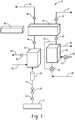
- FIGS. 1 and 2 schematically depict exemplary systems of the invention.
- exemplary fuel and thermal management systems 10 are shown with fuel tank 12 providing fuel through fuel line 14 having temperature sensor 16 and oxygen sensor 18 for measuring dissolved oxygen levels in the fuel.
- a flow meter 20 measures fuel flow rate of fuel entering the system 10.
- Fuel is delivered to optional heat exchanger 22, which transfers heat to the fuel from lubricating oil circulated to an electrical generator (not shown) through oil lines 24, 26 having oil temperature sensor 25, thus raising the temperature of the fuel.
- Optional heat exchanger 22 has separate sections in thermal communication with one another, with one of the sections accommodating oil circulating to the generator and another section accommodating fuel.
- Lubricating oil from an engine is circulated to a first heat exchanger 28 through oil inlet line 30 having a bypass valve 32.
- Bypass valve 32 is configured to controllably distribute oil between a flow path through heat exchanger 28 and a flow path through oil bypass line 34.
- First heat exchanger 28 transfers heat from the engine oil flowing through a first section (not shown) of the heat exchanger to ambient air flowing through or across a second section (not shown) of the heat exchanger.
- Air is depicted circulating through air lines 36, 38 having a control valve 40 for controlling the amount of air flow. Oil temperature is measured downstream of the first heat exchanger 28 and oil bypass 34 with temperature sensor 42.
- Engine oil flows from the first heat exchanger 28 and oil bypass 34 to second heat exchanger 44, where it flows through a third heat exchanger section (not shown) and transfers heat to fuel flowing through a fourth heat exchanger section (not shown).
- Temperature of engine oil at the second heat exchanger 44 is measured by temperature sensors 42, 45, upstream and downstream, respectively, of the second heat exchanger 44. After the oil passes temperature sensor 45, it flows out of the system through oil outlet line 47 from where it is returned to the engine.
- downstream means in the direction of oil flow within the fuel and thermal management system (illustrated in FIGS. 1 and 2 as flow in the direction between inlet line 30 and oil outlet line 47 in FIGS. 1 and 2 ), and upstream means in the opposite direction of downstream.
- Fuel is introduced to the second heat exchanger 44 from the heat exchanger 22 (if present) or directly from the fuel tank 12. Temperature of fuel at the second heat exchanger 44 is measured by temperature sensors 46, 48, upstream and downstream, respectively, of the second heat exchanger 44. Fuel exiting the second heat exchanger 44 is delivered through fuel line 50 to an engine fuel inlet (not shown). As used herein, with respect to the fuel, downstream means in the direction of fuel within the fuel and thermal management system (illustrated in FIGS. 1 and 2 as the direction of flow between fuel tank 12 and fuel line 50), and upstream means in the opposite direction of downstream.
- an optional fuel stabilization unit (FSU) 52 is shown in fluid communication with fuel line 14.
- Bypass valve 54 controllably distributes fuel between a flow path leading downstream to the heat exchanger 22 and a flow path circulating to FSU 52.
- the FSU 52 is used to reduce dissolved oxygen content in the fuel.
- FSU's are well-known in the art, and do not require detailed explanation herein.
- FSU's typically utilize membranes and/or chemical or electrochemical materials, components, and techniques to deoxygenate fuel. Exemplary FSU's are described, for example, in US Patents 8,177,884 , 7,615,104 , and 7,431,818 .
- ECU 56 an electronic controller (i.e., electronic control unit or ECU) 56 is shown.
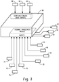
- ECU 56 is connected to the various sensors and controllable components shown in FIGS. 1 and 2 , as well as to other aircraft components and systems not shown in FIGS. 1 and 2 . For ease of illustration, these connections are shown in a separate figure, FIG. 3 .
- ECU 56 receives aircraft data inputs from systems or sensors providing data on measurements such as altitude 58, thrust 60, and outside air temperature 62. These measurements can be used by the ECU 56 to determine an optimal or target temperature for the fuel being delivered to the engine in order to enhance engine performance at the conditions under which it is operating.
- fuel system 10 is engaged to provide increased fuel temperature at typical cruising altitudes.
- ECU 56 also receives inputs from oxygen sensor 18, fuel temperature sensors 16, 46, and 48, oil temperature sensors 25, 42, and 45, and fuel flow meter 20.
- ECU 56 provides output signals to bypass valve 32, control valve 40, and bypass valve 54.
- ECU 56 controls the bypass valve 32 and control valve 40, to achieve a target fuel temperature delivered to the engine, with the proviso that fuel temperature at the second heat exchanger 44 is maintained below a variably set level based on dissolved oxygen content in the fuel reported by the output of oxygen sensor 18.
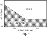
- the ECU 56 accomplishes this by comparing the dissolved oxygen content reported by oxygen sensor 18 with information electronically stored in ECU 56 on the formation of fuel deposits (i.e., the susceptibility or tendency of the fuel to form deposits) as a function of fuel temperature.
- FIG. 4 depicts two domains as a function of fuel temperature and dissolved oxygen level in the fuel.
- One of the domains is designated as a deposit-free or reduced deposit domain where deposit formation does not occur or occurs at an acceptable level for continued system health and operation.
- the other domain is designated as a 'Deposits' domain, where deposits occur at an unacceptable level for continued system health and operation.
- higher temperatures and/or higher levels of dissolved oxygen favor deposit formation whereas lower temperatures and/or lower levels of dissolved oxygen favor away from deposit formation.
- the information represented by FIG. 4 can be stored in the ECU 56 in the form of a lookup table, such as a table of maximum allowable temperature at which fuel deposits are at an acceptable level for a specified fuel oxygen level.
- the information represented by FIG. 4 can also be stored in the ECU 56 in the form of a mathematical function that plots the dividing line between the two domains shown in FIG. 4 as a function of temperature and oxygen content.
- the ECU 56 attempts to achieve the target delivered fuel temperature by controlling amounts of engine oil and ambient airflow through the first heat exchanger 28.
- the amount of oil flowing through the first heat exchanger 28 is controlled by setting the oil bypass valve 32 to direct greater or lesser amounts of oil through the heat exchanger 28 versus through the oil bypass conduit 34.
- the amount of airflow is controlled by setting the control valve 40. Greater amounts of oil and/or air flowing through the first heat exchanger 28 tend to reduce the temperature of the oil whereas lower amounts of oil and/or air flowing through the first heat exchanger 28 tend to increase the temperature of the oil. Higher oil temperatures cause higher fuel temperatures at the second heat exchanger 44.
- the ECU 56 described above may provide for an engine oil temperature to be achieved that provides an amount of heat transfer in the second heat exchanger 44 to achieve a target or desired fuel temperature delivered to the engine.
- the ECU 56 may also provide a maximum fuel temperature delivered to the engine that can be achieved without incurring an unacceptable level of fuel coke or varnish deposits
- the temperature of the engine oil is controlled by the setting the airflow and bypass ratio (i.e., amount of oil flowing through bypass conduit 34 versus through the heat exchanger 28) so as not to exceed the target temperature.
- the valve settings are controlled so that the fuel temperature does not exceed level based on dissolved oxygen content in the fuel.
- the target temperature is at or below the maximum temperature allowed for avoiding deposits at the measured oxygen concentration. In some embodiments, however, the target fuel temperature is above such a maximum allowable temperature.
- the ECU 56 can be configured to determine or predict whether dissolved oxygen content can or will be reduced by expected changes brought about by altitude changes and/or the operation of inert gassing systems where inert gas such as nitrogen is bubbled through fuel in the fuel into the fuel tank's gas space (i.e., ullage).
- the ECU 56 can control the inert gassing level in order to reduce the dissolved oxygen content in the fuel.
- ECU 56 controls an amount of fuel diverted into FSU 52 by setting bypass valve 54.
- the load on the FSU 52 can thus be controlled to the minimum level needed in order to enable the system 10 to achieve the target fuel temperature, so that overall load on the FSU 52 as well as its design capacity requirements can be reduced compared to a system without the integrated control provided by the invention.
- the electronic controller is configured to set a position of the oil bypass valve and/or a position of the control valve during operation of the system further in response to: (iii) stored information on the formation of fuel deposits as a function of fuel temperature and dissolved oxygen content of the fuel.
- the electronic controller is configured to set the oil bypass valve to increase engine oil flow through the first heat exchanger, and/or to set the control valve to increase air flow through the first heat exchanger, the oil bypass and/or control valves set in response to a determination that engine oil temperature or fuel temperature is above a variably set level based on dissolved oxygen content of the fuel.
- system further comprises a third heat exchanger comprising a fifth section in fluid communication with the fuel, and a sixth section in thermal communication with the fifth section and in fluid communication with generator oil, wherein the fifth section is in fluid communication with and upstream of the third heat exchanger section.
- the system also includes a first temperature sensor in thermal communication with the engine oil upstream of the second heat exchanger and a second temperature sensor in thermal communication with the engine oil downstream of the second heat exchanger, wherein the electronic controller determines temperature of the engine oil at the second heat exchanger based on output from the first and second temperature sensors.
- the system also includes a third temperature sensor in thermal communication with the fuel upstream of the second heat exchanger and a second temperature sensor in thermal communication with the fuel downstream of the second heat exchanger, wherein the electronic controller determines temperature of the fuel at the second heat exchanger based on output from the third and fourth temperature sensors.
- the controller is configured to set the positions of the oil bypass and control valves to maximize transfer of heat from the engine oil to the fuel in the second heat exchanger, with the proviso that fuel temperature at the second heat exchanger is maintained below a variably set level based on dissolved oxygen content in the fuel.
- the system also includes a fuel stabilization unit in fluid communication with the fuel upstream of the heat exchangers, for removing dissolved oxygen from the fuel.
- the system also includes a fuel bypass valve configured to selectively distribute a flow of fuel between a first fuel flow path leading to the second heat exchanger without passing through the fuel stabilization unit and a second fuel flow path leading to the second heat exchanger through the fuel stabilization unit.
- the electronic controller is also configured to control a position of the fuel bypass valve to achieve a target content of dissolved fuel oxygen in the fuel.
- the target dissolved fuel oxygen content is determined based on a target fuel temperature desired at the second heat exchanger.
Landscapes
- Engineering & Computer Science (AREA)
- Chemical & Material Sciences (AREA)
- Combustion & Propulsion (AREA)
- Mechanical Engineering (AREA)
- General Engineering & Computer Science (AREA)
- Physics & Mathematics (AREA)
- General Physics & Mathematics (AREA)
- Automation & Control Theory (AREA)
- Aviation & Aerospace Engineering (AREA)
- Feeding And Controlling Fuel (AREA)
Claims (15)
- Brennstoff- und Temperaturverwaltungssystem (10) zur Abgabe von Brennstoff an einen Motor, umfassend:eine Brennstoffversorgungsleitung (14) in Fluidverbindung zwischen einem Brennstofftank (12) und einem Brennstoffeinlass des Motors;einen ersten Wärmetauscher (28), umfassend einen ersten Abschnitt in Fluidverbindung mit Motoröl und einen zweiten Abschnitt in thermischer Verbindung mit dem ersten Abschnitt und in Fluidverbindung mit Umgebungsluft;einen zweiten Wärmetauscher (44), umfassend einen dritten Abschnitt in Fluidverbindung mit der Brennstoffleitung (14) und einen vierten Abschnitt in thermischer Verbindung mit dem ersten Abschnitt und in Fluidverbindung mit Motoröl, wobei der vierte Abschnitt in Fluidverbindung mit und stromabwärts von dem ersten Wärmetauscherabschnitt (28) ist;eine Motorölbypassleitung (34) in Fluidverbindung mit dem Motoröl stromaufwärts von dem ersten Wärmetauscher (28) und mit dem Motoröl stromabwärts von dem ersten Wärmetauscher (28) und stromaufwärts von dem zweiten Wärmetauscher (44);ein Ölbypassventil (32) in Fluidverbindung mit dem Motoröl stromaufwärts von dem ersten Wärmetauscher (28), wobei das Ölbypassventil (32) dazu ausgelegt ist, selektiv einen Motorölstrom zwischen dem ersten Wärmetauscherabschnitt und der Motorölbypassleitung (34) zu verteilen;ein Steuerungsventil (40) in Fluidverbindung mit dem zweiten Wärmetauscherabschnitt des ersten Wärmetauschers (28), dazu ausgelegt, einen Umgebungsluftstrom durch den zweiten Wärmetauscherabschnitt zu steuern; dadurch gekennzeichnet, dassdas System einen Sauerstoffsensor (18) in Fluidverbindung mit der Brennstoffversorgungsleitung (14) zum Messen des Gehalts an gelöstem Sauerstoff in dem Brennstoff umfasst; undeine elektronische Steuerung (56) dazu ausgelegt ist, eine Position des Ölbypassventils (32) und/oder eine Position des Steuerungsventils (40) während des Betriebs des Systems als Reaktion auf Folgendes einzustellen: den Gehalt an gelöstem Sauerstoff des Brennstoffs; und die Temperatur des Motoröls und/oder des Brennstoffs an dem zweiten Wärmetauscher (44).
- System (10) nach Anspruch 1, wobei die elektronische Steuerung (56) dazu ausgelegt ist, eine Position des Ölbypassventils (32) und/oder eine Position des Steuerungsventils (32) während des Betriebs des Systems ferner als Reaktion auf gespeicherte Informationen über die Bildung von Brennstoffablagerungen in Abhängigkeit von der Brennstofftemperatur und dem Gehalt an gelöstem Sauerstoff des Brennstoffs einzustellen.
- System nach Anspruch 1 oder 2, wobei die elektronische Steuerung (56) dazu ausgelegt ist, das Ölbypassventil (32) einzustellen, um den Motorölstrom durch den ersten Wärmetauscher (28) zu erhöhen, und/oder, das Steuerungsventil (40) einzustellen, um den Luftstrom durch den ersten Wärmetauscher (28) zu erhöhen, wobei das Ölbypass- und/oder Steuerungsventil (32, 40) als Reaktion auf eine Bestimmung eingestellt wird, dass die Motoröltemperatur oder Brennstofftemperatur über einem variabel eingestellten Niveau basierend auf dem Gehalt an gelöstem Sauerstoff des Brennstoffs ist.
- Das System (10) nach einem der Ansprüche 1 bis 3, ferner umfassend einen dritten Wärmetauscher, umfassend einen fünften Abschnitt in Fluidverbindung mit dem Brennstoff und einen sechsten Abschnitt in thermischer Verbindung mit dem fünften Abschnitt und in Fluidverbindung mit Generatoröl, wobei der fünfte Abschnitt in Fluidverbindung mit dem und stromaufwärts von dem dritten Wärmetauscherabschnitt ist.
- System (10) nach einem der Ansprüche 1 bis 4, ferner umfassend einen ersten Temperatursensor (42) in thermischer Verbindung mit dem Motoröl stromaufwärts von dem zweiten Wärmetauscher (44) und einen zweiten Temperatursensor (45) in thermischer Verbindung mit dem Motoröl stromabwärts von dem zweiten Wärmetauscher (44), wobei die elektrische Steuerung (56) die Temperatur des Motoröls an dem zweiten Wärmetauscher (44) basierend auf einer Ausgabe des ersten und des zweiten Temperatursensors (42, 45) bestimmt.
- System (10) nach Anspruch 5, ferner umfassend einen dritten Temperatursensor (46) in thermischer Verbindung mit dem Brennstoff stromaufwärts von dem zweiten Wärmetauscher (44) und einen zweiten Temperatursensor (48) in thermischer Verbindung mit dem Brennstoff stromabwärts von dem zweiten Wärmetauscher (44), wobei die elektrische Steuerung (56) die Temperatur des Brennstoffs an dem zweiten Wärmetauscher (44) basierend auf einer Ausgabe von dem dritten und vierten Temperatursensor (46, 48) bestimmt.
- System (10) nach einem der Ansprüche 1 bis 6, wobei die Steuerung (56) dazu ausgelegt ist, die Positionen des Ölbypass- und des Steuerungsventils (32, 40) einzustellen, um Wärmeübertragung von dem Motoröl zu dem Brennstoff in dem zweiten Wärmetauscher mit der Maßgabe zu maximieren, dass die Brennstofftemperatur an dem zweiten Wärmetauscher (44) unter einem variabel eingestellten Niveau basierend auf dem Gehalt an gelöstem Sauerstoff in dem Brennstoff gehalten wird.
- System (10) nach einem der Ansprüche 1 bis 7, ferner umfassend eine Brennstoffstabilisierungseinheit (52) in Fluidverbindung mit dem Brennstoff stromaufwärts von den Wärmetauschern (28, 44) zum Entfernen von gelöstem Sauerstoff von dem Brennstoff.
- System (10) nach Anspruch 8, ferner umfassend ein Brennstoffbypassventil (54), dazu ausgelegt, selektiv einen Brennstoffstrom zwischen einem ersten Brennstoffströmungsweg, der zu dem zweiten Wärmetauscher (44) führt, ohne durch die Brennstoffstabilisierungseinheit (52) zu laufen, und einem zweiten Brennstoffströmungsweg zu verteilen, der durch die Brennstoffstabilisierungseinheit (52) zu dem zweiten Wärmetauscher (44) führt.
- Das System (10) nach Anspruch 8 oder 9, wobei die elektrische Steuerung (56) dazu ausgelegt ist, eine Position des Brennstoffbypassventils (54) zu steuern, um einen Zielgehalt an gelöstem Sauerstoff in dem Brennstoff zu erreichen.
- System (10) nach Anspruch 10, wobei der Zielgehalt an gelöstem Brennstoffsauerstoff basierend auf einer Zielbrennstofftemperatur bestimmt wird, die an dem zweiten Wärmetauscher (44) erwünscht ist.
- Verfahren zum Temperaturverwalten und Abgeben von Brennstoff an einen Motor, umfassend:Messen der Konzentration von gelöstem Sauerstoff in dem Brennstoff;Erhitzen des Brennstoffs in einem zweiten Wärmetauscher (44) mit Wärme von Öl, die von dem Motor umgewälzt wird, dadurch gekennzeichnet, dass das Verfahren Folgendes umfasst:steuerbares Leiten, basierend auf dem Gehalt an gelöstem Sauerstoff des Brennstoffs und der Temperatur des Motoröls und/oder des Brennstoffs an dem zweiten Wärmetauscher (44), einer Menge des umgewälzten Öls durch einen ersten Wärmetauscher (28), um umgewälztes Öl zu kühlen.
- Verfahren nach Anspruch 12, ferner umfassend Steuern einer Menge des umgewälzten Öls durch einen Bypass (34) um den ersten Wärmetauscher (28) und/oder Steuern einer Menge von Kühlluft, die an den ersten Wärmetauscher (28) abgegeben wird.
- Verfahren nach Anspruch 12 oder 13, ferner umfassend Erhitzen des Brennstoffs in einem dritten Wärmetauscher mit Öl, das von einem Generator umgewälzt wird.
- Verfahren nach einem der Ansprüche 12, 13 oder 14, ferner umfassend Leiten des Brennstoffs durch eine Brennstoffstabilisierungseinheit (52) in Fluidverbindung mit dem Brennstoff stromaufwärts von den Wärmetauschern (28, 44) zum Entfernen von gelöstem Sauerstoff von dem Brennstoff und selektiv Verteilen eines Brennstoffstroms zwischen einem ersten Brennstoffströmungsweg, der zu dem zweiten Wärmetauscher (44) führt, ohne durch die Brennstoffstabilisierungseinheit (52) zu laufen, und einem zweiten Brennstoffströmungsweg, der durch die Brennstoffstabilisierungseinheit (52) zu dem zweiten Wärmetauscher (44) führt.
Applications Claiming Priority (1)
| Application Number | Priority Date | Filing Date | Title |
|---|---|---|---|
| US14/317,748 US9789972B2 (en) | 2014-06-27 | 2014-06-27 | Fuel and thermal management system |
Publications (2)
| Publication Number | Publication Date |
|---|---|
| EP2960158A1 EP2960158A1 (de) | 2015-12-30 |
| EP2960158B1 true EP2960158B1 (de) | 2017-09-13 |
Family
ID=53510663
Family Applications (1)
| Application Number | Title | Priority Date | Filing Date |
|---|---|---|---|
| EP15174155.0A Active EP2960158B1 (de) | 2014-06-27 | 2015-06-26 | Brennstoff- und temperaturverwaltungssystem |
Country Status (2)
| Country | Link |
|---|---|
| US (1) | US9789972B2 (de) |
| EP (1) | EP2960158B1 (de) |
Families Citing this family (19)
| Publication number | Priority date | Publication date | Assignee | Title |
|---|---|---|---|---|
| US9789972B2 (en) | 2014-06-27 | 2017-10-17 | Hamilton Sundstrand Corporation | Fuel and thermal management system |
| US10215097B2 (en) * | 2015-12-08 | 2019-02-26 | General Electric Company | Thermal management system |
| US20180051946A1 (en) * | 2016-08-17 | 2018-02-22 | Hamilton Sundstrand Corporation | Heat exchanger arrangements and related methods |
| US11052328B2 (en) * | 2016-10-25 | 2021-07-06 | Delavan Inc. | Fuel stabilization systems |
| US11187156B2 (en) * | 2017-11-21 | 2021-11-30 | General Electric Company | Thermal management system |
| CN110092003A (zh) * | 2018-01-30 | 2019-08-06 | 哈米尔顿森德斯特兰德公司 | 飞机的油箱催化惰化设备 |
| US10815906B2 (en) * | 2018-03-12 | 2020-10-27 | Raytheon Technologies Corporation | Systems and methods for fuel-based thermal management |
| US11466621B2 (en) | 2019-03-20 | 2022-10-11 | Raytheon Technologies Corporation | Adaptive thermal management system for aircraft fuel system |
| US11773776B2 (en) | 2020-05-01 | 2023-10-03 | General Electric Company | Fuel oxygen reduction unit for prescribed operating conditions |
| US11795878B2 (en) | 2021-02-02 | 2023-10-24 | General Electric Company | High-temperature fuel thermal transport bus architecture |
| US11591965B2 (en) | 2021-03-29 | 2023-02-28 | General Electric Company | Thermal management system for transferring heat between fluids |
| US12115470B2 (en) | 2021-04-27 | 2024-10-15 | General Electric Company | Fuel oxygen reduction unit |
| US12005377B2 (en) | 2021-06-15 | 2024-06-11 | General Electric Company | Fuel oxygen reduction unit with level control device |
| CN115492687B (zh) * | 2021-06-17 | 2025-11-04 | 通用电气公司 | 管理热燃料的控制方法 |
| US11821366B2 (en) | 2021-06-17 | 2023-11-21 | General Electric Company | Methods of control for management of hot fuel |
| US11668241B2 (en) | 2021-06-17 | 2023-06-06 | General Electric Company | Methods of control for management of hot fuel |
| GB202219385D0 (en) * | 2022-12-21 | 2023-02-01 | Rolls Royce Plc | Aircraft combustion systems |
| GB202319134D0 (en) * | 2023-12-14 | 2024-01-31 | Rolls Royce Plc | Gas turbine fuel temperature management |
| GB202319128D0 (en) * | 2023-12-14 | 2024-01-31 | Rolls Royce Plc | Gas turbine fuel temperature |
Family Cites Families (39)
| Publication number | Priority date | Publication date | Assignee | Title |
|---|---|---|---|---|
| US4773212A (en) * | 1981-04-01 | 1988-09-27 | United Technologies Corporation | Balancing the heat flow between components associated with a gas turbine engine |
| US6707492B1 (en) * | 1999-03-31 | 2004-03-16 | Cirrus Logic, Inc. | Successive approximation calibration apparatus, system, and method for dynamic range extender |
| US6315815B1 (en) * | 1999-12-16 | 2001-11-13 | United Technologies Corporation | Membrane based fuel deoxygenator |
| JP4410425B2 (ja) * | 2001-03-05 | 2010-02-03 | 三菱重工業株式会社 | 冷却型ガスタービン排気車室 |
| CN1571879A (zh) * | 2002-03-04 | 2005-01-26 | 三菱重工业株式会社 | 涡轮设备、复合发电设备和涡轮工作方法 |
| US6939392B2 (en) * | 2003-04-04 | 2005-09-06 | United Technologies Corporation | System and method for thermal management |
| US7041154B2 (en) * | 2003-12-12 | 2006-05-09 | United Technologies Corporation | Acoustic fuel deoxygenation system |
| US7260926B2 (en) | 2004-01-20 | 2007-08-28 | United Technologies Corporation | Thermal management system for an aircraft |
| US7231769B2 (en) * | 2004-01-29 | 2007-06-19 | United Technologies Corporation | Gas turbine cooling system |
| US7175693B2 (en) * | 2004-01-30 | 2007-02-13 | United Technologies Corporation | Method for preventing fuel infiltration into microporous polymer membranes |
| US7744827B2 (en) * | 2004-02-13 | 2010-06-29 | United Technologies Corporation | Catalytic treatment of fuel to impart coking resistance |
| US7153343B2 (en) * | 2004-03-24 | 2006-12-26 | United Technologies Corporation | Fuel deoxygenation system |
| US7431818B2 (en) * | 2004-03-26 | 2008-10-07 | United Technologies Corporation | Electrochemical fuel deoxygenation system |
| US7225624B2 (en) * | 2004-06-08 | 2007-06-05 | Allison Advanced Development Company | Method and apparatus for increasing the pressure of cooling fluid within a gas turbine engine |
| US7465335B2 (en) * | 2005-02-02 | 2008-12-16 | United Technologies Corporation | Fuel deoxygenation system with textured oxygen permeable membrane |
| US7329305B2 (en) * | 2005-02-23 | 2008-02-12 | United Technologies Corporation | Membrane based de-oxygenator for process streams |
| US7393388B2 (en) * | 2005-05-13 | 2008-07-01 | United Technologies Corporation | Spiral wound fuel stabilization unit for fuel de-oxygenation |
| US7435283B2 (en) * | 2005-05-18 | 2008-10-14 | United Technologies Corporation | Modular fuel stabilization system |
| US7465336B2 (en) * | 2005-06-09 | 2008-12-16 | United Technologies Corporation | Fuel deoxygenation system with non-planar plate members |
| US7377112B2 (en) * | 2005-06-22 | 2008-05-27 | United Technologies Corporation | Fuel deoxygenation for improved combustion performance |
| US20070101731A1 (en) * | 2005-09-07 | 2007-05-10 | United Technologies Corporation | Deoxygenated fuel-cooled environmental control system pre-cooler for an aircraft |
| US7537646B2 (en) * | 2005-10-11 | 2009-05-26 | United Technologies Corporation | Fuel system and method of reducing emission |
| US7615104B2 (en) * | 2005-11-03 | 2009-11-10 | United Technologies Corporation | Fuel deoxygenation system with multi-layer oxygen permeable membrane |
| US7569099B2 (en) * | 2006-01-18 | 2009-08-04 | United Technologies Corporation | Fuel deoxygenation system with non-metallic fuel plate assembly |
| US7582137B2 (en) * | 2006-01-18 | 2009-09-01 | United Technologies Corporation | Fuel deoxygenator with non-planar fuel channel and oxygen permeable membrane |
| US8776952B2 (en) * | 2006-05-11 | 2014-07-15 | United Technologies Corporation | Thermal management system for turbofan engines |
| US7601203B2 (en) * | 2006-07-07 | 2009-10-13 | United Technologies Corporation | Hybrid vacuum system for fuel deoxygenation |
| US7632338B2 (en) * | 2006-10-05 | 2009-12-15 | United Technologies Corporation | Electrochemical oxygen pump for fuel stabilization unit |
| US7718302B2 (en) * | 2006-10-16 | 2010-05-18 | United Technologies Corporation | Electrochemical deoxygenation of fuel by electrolysis |
| US7882704B2 (en) * | 2007-01-18 | 2011-02-08 | United Technologies Corporation | Flame stability enhancement |
| US8056345B2 (en) * | 2007-06-13 | 2011-11-15 | United Technologies Corporation | Hybrid cooling of a gas turbine engine |
| US20090056342A1 (en) * | 2007-09-04 | 2009-03-05 | General Electric Company | Methods and Systems for Gas Turbine Part-Load Operating Conditions |
| EP2110634B1 (de) * | 2008-04-16 | 2016-10-19 | MAHLE Behr GmbH & Co. KG | Abgasverdampfer eines Kraftfahrzeuges |
| US7984606B2 (en) | 2008-11-03 | 2011-07-26 | Propulsion, Gas Turbine, And Energy Evaluations, Llc | Systems and methods for thermal management in a gas turbine powerplant |
| US8177884B2 (en) | 2009-05-20 | 2012-05-15 | United Technologies Corporation | Fuel deoxygenator with porous support plate |
| US8984856B2 (en) * | 2010-04-12 | 2015-03-24 | Hamilton Sundstrand Corporation | Flexible fuel system |
| US9580185B2 (en) * | 2012-01-20 | 2017-02-28 | Hamilton Sundstrand Corporation | Small engine cooled cooling air system |
| GB201217332D0 (en) | 2012-09-28 | 2012-11-14 | Rolls Royce Plc | A gas turbine engine |
| US9789972B2 (en) | 2014-06-27 | 2017-10-17 | Hamilton Sundstrand Corporation | Fuel and thermal management system |
-
2014
- 2014-06-27 US US14/317,748 patent/US9789972B2/en active Active
-
2015
- 2015-06-26 EP EP15174155.0A patent/EP2960158B1/de active Active
Non-Patent Citations (1)
| Title |
|---|
| None * |
Also Published As
| Publication number | Publication date |
|---|---|
| US20150375868A1 (en) | 2015-12-31 |
| EP2960158A1 (de) | 2015-12-30 |
| US9789972B2 (en) | 2017-10-17 |
Similar Documents
| Publication | Publication Date | Title |
|---|---|---|
| US9789972B2 (en) | Fuel and thermal management system | |
| US9051056B2 (en) | Fuel heat management system | |
| EP3102809B1 (de) | Verfahren zur optimierung der motorleistung mittels kraftstofftemperatur | |
| US7997062B2 (en) | Dual channel regulated fuel-oil heat exchanger | |
| US20100313591A1 (en) | Adaptive heat sink for aircraft environmental control system | |
| US9759130B2 (en) | Gas turbine engine with cooling system | |
| US9097169B2 (en) | Gas turbine engine heat management system | |
| US10526971B2 (en) | Super-cooled heat exchanger of an air cycle machine | |
| US10378421B2 (en) | Automatic transmission fluid thermal conditioning system | |
| KR20070028223A (ko) | 항공기용 탈산소 연료-냉각식 환경 제어 시스템 예비냉각기 | |
| CA2950792A1 (en) | Thermal management system | |
| US20180215479A1 (en) | Heat exchanger system for aircraft and associated method of operation | |
| JP2011502878A (ja) | 航空機から発生する排熱の管理法および同方式の活用を可能ならしめる航空機用冷却装置 | |
| US20120248252A1 (en) | Cooling system for fuel cell systems, method for cooling fuel cell systems, and a fuel cell system | |
| CN116181527A (zh) | 用于飞行器的组合式二氢加热和流体冷却系统以及包括这种系统的飞行器 | |
| US9016351B2 (en) | Preheating device for a fluid/fluid heat exchanger of an aircraft | |
| EP3064753A1 (de) | Motorabhitzerückgewinnungssystem | |
| CN105179104B (zh) | 一种应用于船舶及海洋工程领域的综合热源系统 | |
| US20210292659A1 (en) | Fuel stabilization systems | |
| KR20180028827A (ko) | 여과 기능을 구비하는 연료 점도 조절시스템 | |
| US10710730B2 (en) | Passive OBOGS temperature supply using conditioned avionics cooling | |
| US20220403781A1 (en) | Integrated oil tank with passive thermal modulation | |
| KR102573651B1 (ko) | 이중 연료 엔진용 연료 오일 유량의 측정 유니트 및 동 유니트를 포함하는 연료 오일 공급 시스템, 그리고 이를 포함하는 선박 | |
| KR102526253B1 (ko) | 이중 연료 엔진용 연료 오일 유량의 측정 유니트 및 동 유니트를 포함하는 연료 오일 공급 시스템, 그리고 이를 포함하는 선박 | |
| EP4530457A1 (de) | Doppel-pumpenkraftstoffsystem mit variablem hub mit kühlbypass |
Legal Events
| Date | Code | Title | Description |
|---|---|---|---|
| PUAI | Public reference made under article 153(3) epc to a published international application that has entered the european phase |
Free format text: ORIGINAL CODE: 0009012 |
|
| AK | Designated contracting states |
Kind code of ref document: A1 Designated state(s): AL AT BE BG CH CY CZ DE DK EE ES FI FR GB GR HR HU IE IS IT LI LT LU LV MC MK MT NL NO PL PT RO RS SE SI SK SM TR |
|
| AX | Request for extension of the european patent |
Extension state: BA ME |
|
| 17P | Request for examination filed |
Effective date: 20160630 |
|
| RBV | Designated contracting states (corrected) |
Designated state(s): AL AT BE BG CH CY CZ DE DK EE ES FI FR GB GR HR HU IE IS IT LI LT LU LV MC MK MT NL NO PL PT RO RS SE SI SK SM TR |
|
| GRAP | Despatch of communication of intention to grant a patent |
Free format text: ORIGINAL CODE: EPIDOSNIGR1 |
|
| STAA | Information on the status of an ep patent application or granted ep patent |
Free format text: STATUS: GRANT OF PATENT IS INTENDED |
|
| RAP1 | Party data changed (applicant data changed or rights of an application transferred) |
Owner name: HAMILTON SUNDSTRAND CORPORATION |
|
| INTG | Intention to grant announced |
Effective date: 20170322 |
|
| GRAS | Grant fee paid |
Free format text: ORIGINAL CODE: EPIDOSNIGR3 |
|
| GRAA | (expected) grant |
Free format text: ORIGINAL CODE: 0009210 |
|
| STAA | Information on the status of an ep patent application or granted ep patent |
Free format text: STATUS: THE PATENT HAS BEEN GRANTED |
|
| AK | Designated contracting states |
Kind code of ref document: B1 Designated state(s): AL AT BE BG CH CY CZ DE DK EE ES FI FR GB GR HR HU IE IS IT LI LT LU LV MC MK MT NL NO PL PT RO RS SE SI SK SM TR |
|
| REG | Reference to a national code |
Ref country code: GB Ref legal event code: FG4D |
|
| REG | Reference to a national code |
Ref country code: CH Ref legal event code: EP |
|
| REG | Reference to a national code |
Ref country code: IE Ref legal event code: FG4D |
|
| REG | Reference to a national code |
Ref country code: AT Ref legal event code: REF Ref document number: 927857 Country of ref document: AT Kind code of ref document: T Effective date: 20171015 |
|
| REG | Reference to a national code |
Ref country code: DE Ref legal event code: R096 Ref document number: 602015004622 Country of ref document: DE |
|
| REG | Reference to a national code |
Ref country code: NL Ref legal event code: MP Effective date: 20170913 |
|
| REG | Reference to a national code |
Ref country code: LT Ref legal event code: MG4D |
|
| PG25 | Lapsed in a contracting state [announced via postgrant information from national office to epo] |
Ref country code: SE Free format text: LAPSE BECAUSE OF FAILURE TO SUBMIT A TRANSLATION OF THE DESCRIPTION OR TO PAY THE FEE WITHIN THE PRESCRIBED TIME-LIMIT Effective date: 20170913 Ref country code: FI Free format text: LAPSE BECAUSE OF FAILURE TO SUBMIT A TRANSLATION OF THE DESCRIPTION OR TO PAY THE FEE WITHIN THE PRESCRIBED TIME-LIMIT Effective date: 20170913 Ref country code: NO Free format text: LAPSE BECAUSE OF FAILURE TO SUBMIT A TRANSLATION OF THE DESCRIPTION OR TO PAY THE FEE WITHIN THE PRESCRIBED TIME-LIMIT Effective date: 20171213 Ref country code: HR Free format text: LAPSE BECAUSE OF FAILURE TO SUBMIT A TRANSLATION OF THE DESCRIPTION OR TO PAY THE FEE WITHIN THE PRESCRIBED TIME-LIMIT Effective date: 20170913 Ref country code: LT Free format text: LAPSE BECAUSE OF FAILURE TO SUBMIT A TRANSLATION OF THE DESCRIPTION OR TO PAY THE FEE WITHIN THE PRESCRIBED TIME-LIMIT Effective date: 20170913 |
|
| REG | Reference to a national code |
Ref country code: AT Ref legal event code: MK05 Ref document number: 927857 Country of ref document: AT Kind code of ref document: T Effective date: 20170913 |
|
| PG25 | Lapsed in a contracting state [announced via postgrant information from national office to epo] |
Ref country code: RS Free format text: LAPSE BECAUSE OF FAILURE TO SUBMIT A TRANSLATION OF THE DESCRIPTION OR TO PAY THE FEE WITHIN THE PRESCRIBED TIME-LIMIT Effective date: 20170913 Ref country code: GR Free format text: LAPSE BECAUSE OF FAILURE TO SUBMIT A TRANSLATION OF THE DESCRIPTION OR TO PAY THE FEE WITHIN THE PRESCRIBED TIME-LIMIT Effective date: 20171214 Ref country code: ES Free format text: LAPSE BECAUSE OF FAILURE TO SUBMIT A TRANSLATION OF THE DESCRIPTION OR TO PAY THE FEE WITHIN THE PRESCRIBED TIME-LIMIT Effective date: 20170913 Ref country code: BG Free format text: LAPSE BECAUSE OF FAILURE TO SUBMIT A TRANSLATION OF THE DESCRIPTION OR TO PAY THE FEE WITHIN THE PRESCRIBED TIME-LIMIT Effective date: 20171213 Ref country code: LV Free format text: LAPSE BECAUSE OF FAILURE TO SUBMIT A TRANSLATION OF THE DESCRIPTION OR TO PAY THE FEE WITHIN THE PRESCRIBED TIME-LIMIT Effective date: 20170913 |
|
| PG25 | Lapsed in a contracting state [announced via postgrant information from national office to epo] |
Ref country code: NL Free format text: LAPSE BECAUSE OF FAILURE TO SUBMIT A TRANSLATION OF THE DESCRIPTION OR TO PAY THE FEE WITHIN THE PRESCRIBED TIME-LIMIT Effective date: 20170913 |
|
| PG25 | Lapsed in a contracting state [announced via postgrant information from national office to epo] |
Ref country code: CZ Free format text: LAPSE BECAUSE OF FAILURE TO SUBMIT A TRANSLATION OF THE DESCRIPTION OR TO PAY THE FEE WITHIN THE PRESCRIBED TIME-LIMIT Effective date: 20170913 Ref country code: PL Free format text: LAPSE BECAUSE OF FAILURE TO SUBMIT A TRANSLATION OF THE DESCRIPTION OR TO PAY THE FEE WITHIN THE PRESCRIBED TIME-LIMIT Effective date: 20170913 Ref country code: RO Free format text: LAPSE BECAUSE OF FAILURE TO SUBMIT A TRANSLATION OF THE DESCRIPTION OR TO PAY THE FEE WITHIN THE PRESCRIBED TIME-LIMIT Effective date: 20170913 |
|
| PG25 | Lapsed in a contracting state [announced via postgrant information from national office to epo] |
Ref country code: IS Free format text: LAPSE BECAUSE OF FAILURE TO SUBMIT A TRANSLATION OF THE DESCRIPTION OR TO PAY THE FEE WITHIN THE PRESCRIBED TIME-LIMIT Effective date: 20180113 Ref country code: SM Free format text: LAPSE BECAUSE OF FAILURE TO SUBMIT A TRANSLATION OF THE DESCRIPTION OR TO PAY THE FEE WITHIN THE PRESCRIBED TIME-LIMIT Effective date: 20170913 Ref country code: IT Free format text: LAPSE BECAUSE OF FAILURE TO SUBMIT A TRANSLATION OF THE DESCRIPTION OR TO PAY THE FEE WITHIN THE PRESCRIBED TIME-LIMIT Effective date: 20170913 Ref country code: SK Free format text: LAPSE BECAUSE OF FAILURE TO SUBMIT A TRANSLATION OF THE DESCRIPTION OR TO PAY THE FEE WITHIN THE PRESCRIBED TIME-LIMIT Effective date: 20170913 Ref country code: EE Free format text: LAPSE BECAUSE OF FAILURE TO SUBMIT A TRANSLATION OF THE DESCRIPTION OR TO PAY THE FEE WITHIN THE PRESCRIBED TIME-LIMIT Effective date: 20170913 Ref country code: AT Free format text: LAPSE BECAUSE OF FAILURE TO SUBMIT A TRANSLATION OF THE DESCRIPTION OR TO PAY THE FEE WITHIN THE PRESCRIBED TIME-LIMIT Effective date: 20170913 |
|
| REG | Reference to a national code |
Ref country code: FR Ref legal event code: PLFP Year of fee payment: 4 |
|
| REG | Reference to a national code |
Ref country code: DE Ref legal event code: R097 Ref document number: 602015004622 Country of ref document: DE |
|
| PLBE | No opposition filed within time limit |
Free format text: ORIGINAL CODE: 0009261 |
|
| STAA | Information on the status of an ep patent application or granted ep patent |
Free format text: STATUS: NO OPPOSITION FILED WITHIN TIME LIMIT |
|
| PG25 | Lapsed in a contracting state [announced via postgrant information from national office to epo] |
Ref country code: DK Free format text: LAPSE BECAUSE OF FAILURE TO SUBMIT A TRANSLATION OF THE DESCRIPTION OR TO PAY THE FEE WITHIN THE PRESCRIBED TIME-LIMIT Effective date: 20170913 |
|
| 26N | No opposition filed |
Effective date: 20180614 |
|
| PG25 | Lapsed in a contracting state [announced via postgrant information from national office to epo] |
Ref country code: SI Free format text: LAPSE BECAUSE OF FAILURE TO SUBMIT A TRANSLATION OF THE DESCRIPTION OR TO PAY THE FEE WITHIN THE PRESCRIBED TIME-LIMIT Effective date: 20170913 |
|
| REG | Reference to a national code |
Ref country code: DE Ref legal event code: R119 Ref document number: 602015004622 Country of ref document: DE |
|
| REG | Reference to a national code |
Ref country code: CH Ref legal event code: PL |
|
| REG | Reference to a national code |
Ref country code: BE Ref legal event code: MM Effective date: 20180630 |
|
| REG | Reference to a national code |
Ref country code: IE Ref legal event code: MM4A |
|
| PG25 | Lapsed in a contracting state [announced via postgrant information from national office to epo] |
Ref country code: MC Free format text: LAPSE BECAUSE OF FAILURE TO SUBMIT A TRANSLATION OF THE DESCRIPTION OR TO PAY THE FEE WITHIN THE PRESCRIBED TIME-LIMIT Effective date: 20170913 Ref country code: LU Free format text: LAPSE BECAUSE OF NON-PAYMENT OF DUE FEES Effective date: 20180626 |
|
| PG25 | Lapsed in a contracting state [announced via postgrant information from national office to epo] |
Ref country code: LI Free format text: LAPSE BECAUSE OF NON-PAYMENT OF DUE FEES Effective date: 20180630 Ref country code: IE Free format text: LAPSE BECAUSE OF NON-PAYMENT OF DUE FEES Effective date: 20180626 Ref country code: CH Free format text: LAPSE BECAUSE OF NON-PAYMENT OF DUE FEES Effective date: 20180630 Ref country code: DE Free format text: LAPSE BECAUSE OF NON-PAYMENT OF DUE FEES Effective date: 20190101 |
|
| PG25 | Lapsed in a contracting state [announced via postgrant information from national office to epo] |
Ref country code: BE Free format text: LAPSE BECAUSE OF NON-PAYMENT OF DUE FEES Effective date: 20180630 |
|
| PG25 | Lapsed in a contracting state [announced via postgrant information from national office to epo] |
Ref country code: MT Free format text: LAPSE BECAUSE OF NON-PAYMENT OF DUE FEES Effective date: 20180626 |
|
| PG25 | Lapsed in a contracting state [announced via postgrant information from national office to epo] |
Ref country code: TR Free format text: LAPSE BECAUSE OF FAILURE TO SUBMIT A TRANSLATION OF THE DESCRIPTION OR TO PAY THE FEE WITHIN THE PRESCRIBED TIME-LIMIT Effective date: 20170913 |
|
| PG25 | Lapsed in a contracting state [announced via postgrant information from national office to epo] |
Ref country code: PT Free format text: LAPSE BECAUSE OF FAILURE TO SUBMIT A TRANSLATION OF THE DESCRIPTION OR TO PAY THE FEE WITHIN THE PRESCRIBED TIME-LIMIT Effective date: 20170913 |
|
| PG25 | Lapsed in a contracting state [announced via postgrant information from national office to epo] |
Ref country code: HU Free format text: LAPSE BECAUSE OF FAILURE TO SUBMIT A TRANSLATION OF THE DESCRIPTION OR TO PAY THE FEE WITHIN THE PRESCRIBED TIME-LIMIT; INVALID AB INITIO Effective date: 20150626 Ref country code: CY Free format text: LAPSE BECAUSE OF FAILURE TO SUBMIT A TRANSLATION OF THE DESCRIPTION OR TO PAY THE FEE WITHIN THE PRESCRIBED TIME-LIMIT Effective date: 20170913 Ref country code: MK Free format text: LAPSE BECAUSE OF NON-PAYMENT OF DUE FEES Effective date: 20170913 |
|
| PG25 | Lapsed in a contracting state [announced via postgrant information from national office to epo] |
Ref country code: AL Free format text: LAPSE BECAUSE OF FAILURE TO SUBMIT A TRANSLATION OF THE DESCRIPTION OR TO PAY THE FEE WITHIN THE PRESCRIBED TIME-LIMIT Effective date: 20170913 |
|
| P01 | Opt-out of the competence of the unified patent court (upc) registered |
Effective date: 20230522 |
|
| PGFP | Annual fee paid to national office [announced via postgrant information from national office to epo] |
Ref country code: GB Payment date: 20250520 Year of fee payment: 11 |
|
| PGFP | Annual fee paid to national office [announced via postgrant information from national office to epo] |
Ref country code: FR Payment date: 20250520 Year of fee payment: 11 |