EP4530457A1 - Doppel-pumpenkraftstoffsystem mit variablem hub mit kühlbypass - Google Patents
Doppel-pumpenkraftstoffsystem mit variablem hub mit kühlbypass Download PDFInfo
- Publication number
- EP4530457A1 EP4530457A1 EP24202042.8A EP24202042A EP4530457A1 EP 4530457 A1 EP4530457 A1 EP 4530457A1 EP 24202042 A EP24202042 A EP 24202042A EP 4530457 A1 EP4530457 A1 EP 4530457A1
- Authority
- EP
- European Patent Office
- Prior art keywords
- outlet
- pump
- aps
- fluid communication
- foc
- Prior art date
- Legal status (The legal status is an assumption and is not a legal conclusion. Google has not performed a legal analysis and makes no representation as to the accuracy of the status listed.)
- Pending
Links
Images
Classifications
-
- F—MECHANICAL ENGINEERING; LIGHTING; HEATING; WEAPONS; BLASTING
- F02—COMBUSTION ENGINES; HOT-GAS OR COMBUSTION-PRODUCT ENGINE PLANTS
- F02C—GAS-TURBINE PLANTS; AIR INTAKES FOR JET-PROPULSION PLANTS; CONTROLLING FUEL SUPPLY IN AIR-BREATHING JET-PROPULSION PLANTS
- F02C7/00—Features, components parts, details or accessories, not provided for in, or of interest apart form groups F02C1/00 - F02C6/00; Air intakes for jet-propulsion plants
- F02C7/22—Fuel supply systems
- F02C7/224—Heating fuel before feeding to the burner
-
- F—MECHANICAL ENGINEERING; LIGHTING; HEATING; WEAPONS; BLASTING
- F02—COMBUSTION ENGINES; HOT-GAS OR COMBUSTION-PRODUCT ENGINE PLANTS
- F02C—GAS-TURBINE PLANTS; AIR INTAKES FOR JET-PROPULSION PLANTS; CONTROLLING FUEL SUPPLY IN AIR-BREATHING JET-PROPULSION PLANTS
- F02C7/00—Features, components parts, details or accessories, not provided for in, or of interest apart form groups F02C1/00 - F02C6/00; Air intakes for jet-propulsion plants
- F02C7/12—Cooling of plants
- F02C7/14—Cooling of plants of fluids in the plant, e.g. lubricant or fuel
-
- F—MECHANICAL ENGINEERING; LIGHTING; HEATING; WEAPONS; BLASTING
- F02—COMBUSTION ENGINES; HOT-GAS OR COMBUSTION-PRODUCT ENGINE PLANTS
- F02C—GAS-TURBINE PLANTS; AIR INTAKES FOR JET-PROPULSION PLANTS; CONTROLLING FUEL SUPPLY IN AIR-BREATHING JET-PROPULSION PLANTS
- F02C7/00—Features, components parts, details or accessories, not provided for in, or of interest apart form groups F02C1/00 - F02C6/00; Air intakes for jet-propulsion plants
- F02C7/22—Fuel supply systems
- F02C7/236—Fuel delivery systems comprising two or more pumps
-
- F—MECHANICAL ENGINEERING; LIGHTING; HEATING; WEAPONS; BLASTING
- F02—COMBUSTION ENGINES; HOT-GAS OR COMBUSTION-PRODUCT ENGINE PLANTS
- F02K—JET-PROPULSION PLANTS
- F02K3/00—Plants including a gas turbine driving a compressor or a ducted fan
- F02K3/08—Plants including a gas turbine driving a compressor or a ducted fan with supplementary heating of the working fluid; Control thereof
- F02K3/10—Plants including a gas turbine driving a compressor or a ducted fan with supplementary heating of the working fluid; Control thereof by after-burners
-
- F—MECHANICAL ENGINEERING; LIGHTING; HEATING; WEAPONS; BLASTING
- F05—INDEXING SCHEMES RELATING TO ENGINES OR PUMPS IN VARIOUS SUBCLASSES OF CLASSES F01-F04
- F05D—INDEXING SCHEME FOR ASPECTS RELATING TO NON-POSITIVE-DISPLACEMENT MACHINES OR ENGINES, GAS-TURBINES OR JET-PROPULSION PLANTS
- F05D2260/00—Function
- F05D2260/20—Heat transfer, e.g. cooling
- F05D2260/213—Heat transfer, e.g. cooling by the provision of a heat exchanger within the cooling circuit
Definitions
- the present disclosure relates to fuel systems, and more particularly to fuel systems for aircraft.
- thermal recirculation In modern aircraft it would be advantageous to eliminate the thermal recirculation system. This would reduce the number of fuel system components, and free space for carrying more fuel.
- thermal recirculation cannot typically be eliminated because the fuel oil coolers (FOC) in typical aircraft have over-temperature heat loads at low burn flow conditions, necessitating thermal recirculation systems.
- FOC fuel oil coolers
- a system includes an actuation pump sub-system (APS) with an inlet configured to feed fuel from a fuel source into the actuation pump sub-system, a first outlet configured for connecting the actuation pump sub-system in fluid communication with an actuation system to supply fuel flow for actuation, and a second outlet.
- a fuel oil cooler (FOC) is in a supply line that is in fluid communication with the second outlet.
- a bypass valve (BPV) is in the supply line, in parallel with the FOC, and is configured to allow flow through the supply line bypassing the FOC.
- a main pump and control sub-system (MPCS) has a main inlet connected in fluid communication with the supply line downstream of the BPV and FOC, and a main outlet for supplying fuel to a downstream gas generator.
- the system can be devoid of a thermal recirculation system.
- the system can include the gas generator connected in fluid communication with the main outlet of the MPCS.
- the system can include the actuation system connected in fluid communication with the first outlet of the APS.
- a gearbox can be connected to drive one or more fuel pumps in the APS, and to drive one or more pumps of the MPCS.
- An afterburner pump can be operatively connected to be driven by the gearbox, wherein the afterburner pump is connected in fluid communication to supply an afterburner control.
- the APS can include a boost pump operatively connected between the inlet of the APS and the second outlet of the APS for boosting pressure of fuel from the supply to the pressure in the supply line.
- the APS can include a first variable displacement pump (VDP) with a pump inlet in fluid communication to be supplied with boosted pressure from the boost pump, and a pump outlet connected in fluid communication with the first outlet of the APS.
- An afterburner selector valve (ASV) can be included in a line connecting the pump outlet of the first VDP with the outlet of the APS, wherein the ASV is connected in fluid communication with a line connecting between the afterburner pump and the afterburner control for backup supply to the afterburner control from the APS.
- the APS can include a port connected in fluid communication with the outlet of the boost pump, wherein the port is connected in fluid communication with the actuation systems, with the afterburner pump, and with a port of the MPCS.
- the MPCS can include a second VDP with a pump inlet in fluid communication with the main inlet of the MPCS, and a pump outlet line in fluid communication with the main outlet of the MPCS.
- a windmill bypass valve (WMBV) can be included in fluid communication with a branch of the pump outlet line and with the port of the APS for returning bypass flow to the APS from the second VDP.
- a metering valve (MV) in the pump outlet line can be configured for metering flow to the gas generator.
- a main pump shut off valve (MPSOV) in the pump outlet line downstream of the MV can be configured to stop flow out of the MPCS for shutoff.
- a coarse and wash screens component can be included in the pump outlet line upstream of the WMBV and MV.
- a main filter can be included in a line connecting the boost pump to the second outlet of the APS.
- An actuation filter can be included in the line connecting the pump outlet of the first VDP with the outlet of the APS.
- a controller can be operatively connected to control the BPV, the first and second VDPs, the MPSOV, the WMBV, the MV, the PCV, and the ASV.
- the controller can be operatively connected to sensors in the MPCS and APS for feedback in controlling the BPV, the first and second VDPs, the MPSOV, the WMBV, the MV, the PCV, and the ASV.
- a method of controlling heat transfer in a fuel oil cooler includes flowing fuel into an inlet of the FOC, through the FOC, and out an outlet of the FOC to absorb heat from oil flowing through the FOC while the oil has a temperature above a pre-determined overcooling limit.
- the method includes bypassing the FOC through a bypass valve connected in fluid communication with the inlet and the outlet in parallel with the FOC when the burn flow exceeds oil cooling demand to avoid overcooling the oil beyond a predetermined overcooling limit. Bypassing the FOC can be performed aboard an aircraft without flowing any fuel through any thermal recirculation system of the aircraft.
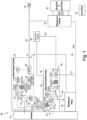
- Fig. 1 is a schematic perspective view of an embodiment of a system constructed in accordance with the present disclosure, showing the dual variable displacement pumps, the fuel oil cooler (FOC), and the bypass valve for bypassing the FOC.
- FOC fuel oil cooler
- Fig. 1 a partial view of an embodiment of a system in accordance with the disclosure is shown in Fig. 1 and is designated generally by reference character 100.
- the systems and methods described herein can be used to eliminate the need for fuel thermal recirculation system, by pairing a thermally efficient fuel system with the ability to modulate fuel flow to the fuel oil cooler (FOC) to prevent overcooling engine oil.
- FOC fuel oil cooler
- the system 100 includes an actuation pump sub-system (APS) 102 with an inlet 104 configured to feed fuel from a fuel source, e.g. at pressure P0, into the APS 102, a first outlet 106 configured for connecting the APS 102 in fluid communication with an actuation system 108 to supply fuel flow for actuation such as for end effectors aboard an aircraft through a line 109.
- a fuel oil cooler (FOC) 110 is in a supply line 112 that is in fluid communication with the second outlet 114 of the APS 102.
- a bypass valve (BPV) 116 is in the supply line 112 in parallel with the FOC 110.
- a main pump and control sub-system (MPCS) 118 has a main inlet 120 connected in fluid communication with the supply line 112 downstream of the BPV 116 and FOC 110.
- the MPCS 118 includes a main outlet 122 for supplying fuel to a downstream gas generator (GG) 124 through a line 125, e.g. at elevated pressure P3.
- the gas generator (GG) can include fuel injectors in a combustor of a gas turbine engine.
- the BPV 116 is configured to allow flow through the supply line 112, bypassing the FOC 110.
- Active control BPV 116 e.g. by the controller 126, can take 0-70% of total flow through the supply line 114, so the system 100 can be devoid of a thermal recirculation system.
- a method of controlling, e.g. by the controller 128, heat transfer in the (FOC) 110 includes flowing fuel into an inlet 128 of the FOC 110, through the FOC 110, and out an outlet 130 of the FOC 110 to absorb heat from oil flowing through the FOC 110 while the oil has a temperature above a pre-determined overcooling limit.
- the method includes bypassing the FOC 110 through a BPV 116 connected in fluid communication with the inlet 128 and the outlet 130 in parallel with the FOC 110 when burn flow of fuel for a particular engine operating condition exceeds oil cooling demand, to avoid overcooling the oil beyond a predetermined overcooling limit. This also helps avoid overheating fuel in heat exchange with the oil without needing a thermal recirculation system on the aircraft. In this manner, bypassing the FOC 110 can be performed aboard an aircraft without flowing any fuel through any thermal recirculation system of the aircraft. If the operation of the BPV 116 can be properly tuned to the predetermined overcooling limit, the BPV 116 can be configured for passive operation as the controller 126 operates the MPCS 118 and the AFS 102.
- a gearbox 132 is connected to drive one or more fuel pumps 134, 136 in the APS 102, and to drive one or more pumps 136 of the MPCS 118.
- An afterburner pump 138 is also operatively connected to be driven by the gearbox 132.
- the afterburner pump 138 is connected in fluid communication to receive flow from the supply line 114 via line 115 and to supply an afterburner control 140, which controls flow of fuel to the manifold and spray bars 142 of an afterburner system of the gas turbine engine of the aircraft.
- the line 144 that connects the afterburner pump 138 in fluid communication with the afterburner control 140 can be pressurized to the elevated pressure, PAFC.
- the APS 102 includes a boost pump 134 operatively connected between the inlet 104 of the APS and the second outlet 114 for boosting pressure of fuel from the supply at P0 to the pressure in the supply line 116, P1.
- a main filter 146 is included in the line connecting the boost pump 134 to the second outlet of the APS 114.
- the APS 102 includes a first variable displacement pump (VDP) 136 with a pump inlet in fluid communication to be supplied with filtered, boosted pressure P1F from the boost pump 134, downstream of the main wash filter 146, and a pump outlet connected in fluid communication by a line 148 with the first outlet 106 of the APS 102.
- An afterburner selector valve (ASV) 150 is included in the line 148.
- An actuation filter 170 is included in the line 148 upstream of the ASV 150.
- the ASV 150 is connected in fluid communication with a line 152 connecting to the line 144 of the afterburner pump 138 for backup supply to the afterburner control 140 from the APS 102.
- the APS 102 includes a port 154 connected in fluid communication with the outlet of the boost pump 134, wherein the port 154 is connected in fluid communication with the actuation systems 108, with the afterburner pump 138, and with a port of the MPCS 118 via a branching line 156 that returns flow from the WMBV 1164, from the actuation system 108, and from the afterburner pump 138, to the boost outlet.
- the MPCS 118 includes a second VDP 158 with a pump inlet in fluid communication with the main inlet 120 of the MPCS 118, and a pump outlet line 160 in fluid communication with the main outlet 122 of the MPCS 118.
- a coarse and wash screens component 162 is included in the pump outlet line 160 upstream of the WMBV 164 and MV 166.
- a windmill bypass valve (WMBV) 164 is in fluid communication with a branch of the pump outlet line 160 and with the port 154 of the APS 102 for returning bypass flow to the APS 102 from the second VDP 158.
- a metering valve (MV) 166 in the pump outlet line 160 is configured for metering flow to the gas generator 124.
- a main pump shut off valve (MPSOV) 168 in the pump outlet line 160 downstream of the MV 166 is configured to stop flow out of the MPCS 118 for shutoff.
- the controller 126 is operatively connected to control the BPV 116 (if it is actively controlled), the first and second VDPs 136, 158, the MPSOV 168, the WMBV 164, the MV 166, the pressure control valve (PCV) 172, and the ASV 150, e.g. by electrically controlling the electrohydraulic servo valves (EHSVs) and solenoids (SOLs) indicated in Fig. 1 .
- EHSVs electrohydraulic servo valves
- SOLs solenoids
- the controller 126 is operatively connected to sensors, including the linear variable differential transformers LVDTs, resistance thermometer RTD, and pressure sensors P, in the MPCS 118 and APS 102 for feedback in controlling the BPV 116 (if it is actively controlled), the first and second VDPs 136, 158, the MPSOV 168, the WMBV 164, the MV 166, the PCV 172, and the ASV 150.
- the controller can include machine readable instructions in the form of analog circuits, solid state digital logic, or a processor can read the instructions to carry out the methods disclosed herin.
- Systems and methods as disclosed herein provide various potential benefits including the following. They can eliminates thermal recirculation systems on aircraft. They can improve fuel system reliability. They can reduce fuel system weight/envelope, and can allow aircraft to carry more fuel.
Landscapes
- Engineering & Computer Science (AREA)
- Chemical & Material Sciences (AREA)
- Combustion & Propulsion (AREA)
- Mechanical Engineering (AREA)
- General Engineering & Computer Science (AREA)
- Details Of Reciprocating Pumps (AREA)
Applications Claiming Priority (1)
| Application Number | Priority Date | Filing Date | Title |
|---|---|---|---|
| US202318374805A | 2023-09-29 | 2023-09-29 |
Publications (1)
| Publication Number | Publication Date |
|---|---|
| EP4530457A1 true EP4530457A1 (de) | 2025-04-02 |
Family
ID=92895830
Family Applications (1)
| Application Number | Title | Priority Date | Filing Date |
|---|---|---|---|
| EP24202042.8A Pending EP4530457A1 (de) | 2023-09-29 | 2024-09-23 | Doppel-pumpenkraftstoffsystem mit variablem hub mit kühlbypass |
Country Status (1)
| Country | Link |
|---|---|
| EP (1) | EP4530457A1 (de) |
Citations (3)
| Publication number | Priority date | Publication date | Assignee | Title |
|---|---|---|---|---|
| RU2458234C1 (ru) * | 2011-04-26 | 2012-08-10 | Открытое акционерное общество "Научно-производственное объединение "Сатурн" (ОАО "НПО "Сатурн") | Способ работы газотурбинного двигателя |
| WO2013165487A2 (en) * | 2012-01-31 | 2013-11-07 | United Technologies Corporation | Gas turbine engine with geared turbofan and oil thermal management system with unique heat exchanger structure |
| US20160108819A1 (en) * | 2013-06-12 | 2016-04-21 | United Technologies Corporation | Fuel/Oil Manifold |
-
2024
- 2024-09-23 EP EP24202042.8A patent/EP4530457A1/de active Pending
Patent Citations (3)
| Publication number | Priority date | Publication date | Assignee | Title |
|---|---|---|---|---|
| RU2458234C1 (ru) * | 2011-04-26 | 2012-08-10 | Открытое акционерное общество "Научно-производственное объединение "Сатурн" (ОАО "НПО "Сатурн") | Способ работы газотурбинного двигателя |
| WO2013165487A2 (en) * | 2012-01-31 | 2013-11-07 | United Technologies Corporation | Gas turbine engine with geared turbofan and oil thermal management system with unique heat exchanger structure |
| US20160108819A1 (en) * | 2013-06-12 | 2016-04-21 | United Technologies Corporation | Fuel/Oil Manifold |
Similar Documents
| Publication | Publication Date | Title |
|---|---|---|
| CA2492914C (en) | Improved fuel delivery system | |
| US8196385B2 (en) | Turbomachine control system | |
| EP3067534B1 (de) | Brennstoff/schmierstoff-wärmeaustauschsystem einer gastubrine | |
| US7509793B2 (en) | Fluid system | |
| EP2784270B1 (de) | Brennstoff- und Betätigungssystem für Gasturbinenmotor sowie dazugehöriges Verfahren | |
| EP2587024B1 (de) | Wärmemanagementsystem in einem Gasturbinentriebwerk | |
| US2925712A (en) | Aircraft fuel system with fuel heating means | |
| US8951021B2 (en) | Dual pump/dual bypass fuel pumping system | |
| US10823074B2 (en) | Recirculation of fluid through a turbomachine centrifugal pump | |
| GB2501198A (en) | Fuel circuit of an aeronautical turbine engine having a fuel pressure regulating valve | |
| CN109882293B (zh) | 涡轮喷气发动机的具有燃料/空气换热器的液压和气动控制回路 | |
| EP3034839B1 (de) | Mittel und anordnung für einen kraftstoffvereisungsschutz | |
| CN116529470A (zh) | 航空器涡轮发动机组件,包括用于旁通燃料/油热交换器的被动阀 | |
| EP1769208B1 (de) | Wärmetauscher | |
| US6446437B1 (en) | Fuel system | |
| EP4530457A1 (de) | Doppel-pumpenkraftstoffsystem mit variablem hub mit kühlbypass | |
| US12345203B2 (en) | Direct controlled variable displacement pump fuel systems with low pressure thermal recirculation pumping | |
| EP4467797B1 (de) | Direktgesteuerte verstellpumpen mit thermostatisch gesteuertem bypass | |
| US12241418B2 (en) | Dedicated thermal recirculation control |
Legal Events
| Date | Code | Title | Description |
|---|---|---|---|
| PUAI | Public reference made under article 153(3) epc to a published international application that has entered the european phase |
Free format text: ORIGINAL CODE: 0009012 |
|
| STAA | Information on the status of an ep patent application or granted ep patent |
Free format text: STATUS: THE APPLICATION HAS BEEN PUBLISHED |
|
| AK | Designated contracting states |
Kind code of ref document: A1 Designated state(s): AL AT BE BG CH CY CZ DE DK EE ES FI FR GB GR HR HU IE IS IT LI LT LU LV MC ME MK MT NL NO PL PT RO RS SE SI SK SM TR |
|
| STAA | Information on the status of an ep patent application or granted ep patent |
Free format text: STATUS: REQUEST FOR EXAMINATION WAS MADE |
|
| 17P | Request for examination filed |
Effective date: 20251001 |