EP2960134B1 - Switch machine for railway and tramway switches or the like - Google Patents
Switch machine for railway and tramway switches or the like Download PDFInfo
- Publication number
- EP2960134B1 EP2960134B1 EP15175255.7A EP15175255A EP2960134B1 EP 2960134 B1 EP2960134 B1 EP 2960134B1 EP 15175255 A EP15175255 A EP 15175255A EP 2960134 B1 EP2960134 B1 EP 2960134B1
- Authority
- EP
- European Patent Office
- Prior art keywords
- switch machine
- actuator
- case
- switch
- lock
- Prior art date
- Legal status (The legal status is an assumption and is not a legal conclusion. Google has not performed a legal analysis and makes no representation as to the accuracy of the status listed.)
- Active
Links
- 239000012530 fluid Substances 0.000 claims description 27
- 239000000463 material Substances 0.000 claims description 17
- 239000003822 epoxy resin Substances 0.000 claims description 9
- 229920000647 polyepoxide Polymers 0.000 claims description 9
- 230000013011 mating Effects 0.000 claims description 4
- 238000000034 method Methods 0.000 claims description 4
- 239000011324 bead Substances 0.000 claims description 3
- 239000000919 ceramic Substances 0.000 claims description 3
- 230000007480 spreading Effects 0.000 claims description 3
- 238000006073 displacement reaction Methods 0.000 description 25
- 230000006835 compression Effects 0.000 description 5
- 238000007906 compression Methods 0.000 description 5
- 230000008878 coupling Effects 0.000 description 4
- 238000010168 coupling process Methods 0.000 description 4
- 238000005859 coupling reaction Methods 0.000 description 4
- 238000010276 construction Methods 0.000 description 3
- 239000002184 metal Substances 0.000 description 3
- 229910052751 metal Inorganic materials 0.000 description 3
- XEEYBQQBJWHFJM-UHFFFAOYSA-N Iron Chemical compound [Fe] XEEYBQQBJWHFJM-UHFFFAOYSA-N 0.000 description 2
- 238000005299 abrasion Methods 0.000 description 1
- 238000005452 bending Methods 0.000 description 1
- 238000005266 casting Methods 0.000 description 1
- 230000008859 change Effects 0.000 description 1
- 238000004891 communication Methods 0.000 description 1
- LNEPOXFFQSENCJ-UHFFFAOYSA-N haloperidol Chemical compound C1CC(O)(C=2C=CC(Cl)=CC=2)CCN1CCCC(=O)C1=CC=C(F)C=C1 LNEPOXFFQSENCJ-UHFFFAOYSA-N 0.000 description 1
- 229910052742 iron Inorganic materials 0.000 description 1
- 239000007769 metal material Substances 0.000 description 1
- 239000003973 paint Substances 0.000 description 1
- 238000010422 painting Methods 0.000 description 1
- 230000008569 process Effects 0.000 description 1
- 239000011253 protective coating Substances 0.000 description 1
- 229920005989 resin Polymers 0.000 description 1
- 239000011347 resin Substances 0.000 description 1
- 239000000126 substance Substances 0.000 description 1
- 230000001360 synchronised effect Effects 0.000 description 1
- 238000011144 upstream manufacturing Methods 0.000 description 1
- 238000003466 welding Methods 0.000 description 1
Images


Classifications
-
- B—PERFORMING OPERATIONS; TRANSPORTING
- B61—RAILWAYS
- B61L—GUIDING RAILWAY TRAFFIC; ENSURING THE SAFETY OF RAILWAY TRAFFIC
- B61L5/00—Local operating mechanisms for points or track-mounted scotch-blocks; Visible or audible signals; Local operating mechanisms for visible or audible signals
- B61L5/04—Fluid-pressure devices for operating points or scotch-blocks
-
- B—PERFORMING OPERATIONS; TRANSPORTING
- B61—RAILWAYS
- B61L—GUIDING RAILWAY TRAFFIC; ENSURING THE SAFETY OF RAILWAY TRAFFIC
- B61L5/00—Local operating mechanisms for points or track-mounted scotch-blocks; Visible or audible signals; Local operating mechanisms for visible or audible signals
- B61L5/10—Locking mechanisms for points; Means for indicating the setting of points
-
- E—FIXED CONSTRUCTIONS
- E01—CONSTRUCTION OF ROADS, RAILWAYS, OR BRIDGES
- E01B—PERMANENT WAY; PERMANENT-WAY TOOLS; MACHINES FOR MAKING RAILWAYS OF ALL KINDS
- E01B7/00—Switches; Crossings
- E01B7/22—Special sleepers for switches or crossings; Fastening means therefor
Definitions
- the invention relates to a switch machine, according to the preamble of claim 1, for railway and tramway switches or the like, having a housing case for its operating units of the same size as a tie and adapted to be installed like a tie.
- Switch machines of this type are known, for example from EP1594732B1 , and widely used and generally comprise a metal case, e.g. formed by iron casting or structural steelwork, with sheet bending, welding, etc.
- Prior art switch machines of this type usually have a protective coating, consisting of plain paint.
- Such switch machines have the drawback of having railway ballast interface surface characteristics that cause ballast to tend to move due to the vibrations induced by running trains.
- the ballast may be significantly displaced and create gaps below and around the switch machine, thereby affecting rail stability and support, and requiring earthing up of the ballast.
- the present invention has the purpose of obviating the above drawbacks of prior art switch machines with a switch machine as described above, whose outer surface further has a covering on at least part of the case, which covering consists of a material, comprising an epoxy resin, having railway ballast interface surface characteristics similar to concrete.
- said surface characteristics are roughness, friction coefficient and hardness.
- said material has a hardness ranging from 60 to 100 Shore, preferably from 70 to 85 Shore, particularly of 75 Shore.
- said epoxy resin is filled with ceramic beads.
- said material has a thickness ranging from 2 to 10 mm, preferably from 4 to 8 mm, preferably of 6 mm.
- the covering with the above mentioned properties imparts concrete-like ballast interface characteristics and overcomes the above mentioned ballast displacement problems.
- the covering ensures an excellent protection of the switch machine, so that the expected life of the switch machine may be increased to 30 years.
- the covering may be applied to the outer surface of the case in any manner whatever.
- said material is applied to said outer covering surface by manual and/or automatic spreading.
- said material is applied to said outer surface of the case by embedment, i.e. by placing said case in a negative mold that has an inner mold surface mating with said outer surface of the case, said negative mold being previously filled with said material in a fluid phase.
- Such second application method is particularly advantageous in many applications, in which the construction of molds is economically supported by great numbers of uses thereof.
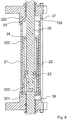
- FIGS 1 to 4 show the switch machine 1, which comprises a switch point shifting actuator, particularly a hydraulic cylinder 2.
- the actuator 2 displaces the points, using actuation drive means, between two limit positions, one of which positions is called normal position and the other of said two positions is called reverse position, and in which positions each of the two points is thrown or open relative to the closest rail, in alternation with the other point.
- the shifting stroke of the points between said two positions having a predetermined length matches a given actuation stroke of the actuator 2.
- Lock/unlock means are further provided for locking/unlocking said points in one of said limit positions, referred to as switch point lock means, which switch point lock means are driven into their unlocking state by said actuator 2, through an initial actuation overstroke, whose end coincides with the point unlocked state, and with the time at which said point shifting actuation stroke starts, whereas the end of the point shifting actuation stroke, in which one of the points is moved from an open position to a thrown position relative to the closest rail and the other point is moved from a thrown position to an open position relative to the closest rail, coincides with the time at which a final actuation overstroke, through which said actuator 2 drives said point locking means into their locking state.
- the switch machine 1 and at least the actuator 2 and said actuation drive means and at least said switch point lock means have a modular construction.
- Said switch point lock means consist of two point pulling and locking modules 30 and 31, which are located at the opposite ends of said hydraulic cylinder 2.
- Each point pulling and locking module has its own case or frame, which case or frame has means for fastening it in predetermined positions, cooperating with coincident fastener means, in predetermined positions on the tie-like box module 100 in which the switch machine 1 is housed.
- the tie-like box module 100 consists of a C or ⁇ -shaped section, open at its top as a channel and closed by one or more covers.
- the tie-like box module 100 has lateral longitudinal fins 101 having holes in predetermined positions for receiving cover elements and/or lateral flanges for fastening operating modules such as the point pulling and locking modules 30 and 31.
- the point pulling and locking modules 30 and 31 also have holes at predetermined positions coinciding with the holes of the tie-like box module 100 and are mounted in a predetermined position with reference to the tie-like box module using fastener means.
- end heads 130 that may also be removably fastened or possibly welded.
- a portion of the cover of the tie-like box module 100 is formed by the upper cover of the modules, whereas the portions of the tie-like box module 100 that are open at their top as they are not filled by operating units are closed by a plurality of cover elements having the same size as said open or exposed parts.
- cover elements are referenced 260, 261 and 262.
- One end of the switch machine 1 is designed for connection with fluid supply lines and/or power lines for any electronic diagnostic system or the like.
- Each of the point pulling and locking modules 30 and 31 has a pulling rod 144 which is dynamically connected to pulling sliders 145 that project out of an upper fastening plate 146.
- the fastening plate 146 has lateral holes for fixation to the lateral longitudinal fins 101 of the tie-like box module 100 and also forms the closing cover of said tie-like box module 100 when the pulling and locking module is mounted to the tie-like box module itself.
- the pulling sliders 145 have a positive geometry mating with the negative seat in the brackets for connection to the points.
- the pulling rod 144 has a removable terminal for connection to the actuator 2 or to further actuation drive means.
- Means are further provided for adjusting the actuation stroke exerted by the actuator 2, which operate to cause the actuator 2 to exert a first predetermined actuation force during the initial actuation overstroke to unlock said point switch lock means, a second predetermined actuation force during said point shifting actuation stroke and a third predetermined actuation stroke during the final actuation overstroke to lock the point lock means.
- the actuator 2 may consist of any kind of motor, such as an electric motor and a kinematic drive chain, which kinematic drive chain may be of any type and consist, for instance, of a screw-and-nut or recirculating-ball assembly.
- the actuation force exerted by the actuator 2 may be controlled by setting the force to be generated by the motor.
- said kinematic drive chain may change the drive ratio according to the stroke that has been run: a first drive ratio is used for the initial actuation overstroke, a second drive ratio is used for the point shifting actuation stroke, and a third drive ratio is used for the final actuation overstroke.
- the actuator 2 is a hydraulic actuator, particularly a hydraulic cylinder 2, which is connected to at least one delivery branch and at least one return branch of a closed hydraulic fluid circulation circuit.
- the means for adjusting the actuation force exerted by the actuator 2 consist of means for setting the fluid delivery to the actuator 2, particularly comprising at least one adjustable flow pump.
- the pump may be a positive-displacement pump controlled at a variable speed and having a predetermined fixed displacement.
- positive-displacement pump is intended to designate a pump having a suction/compression chamber of predetermined volume, which changes fluid delivery according to the speed of actuation of a suction/compression member.
- a particular positive-displacement pump is the piston or gear pump.
- the volume of pressure fluid that can be delivered per unit of time is determined by the displacement and number of suction/compression strokes of the piston.
- other types of pumps may be considered as positive-displacement pumps according to the definition as used herein, such as rotor pumps and/or pumps having suction/compression members based on the Wankel engine principle, in which the suction/compression chamber has a fixed and predetermined volume.
- two or three or more pumps with different displacements may be provided, one or more of which are designed to be alternately and specially driven for actuating a particular operating step of the switch machine 1.
- the use of multiple positive-displacement pumps is generally disclosed in EP 2192020 .
- said force adjustment means consist of the actuator 2 itself.
- the actuator 2 consists of a hydraulic cylinder 2 which comprises at least one pushing or pulling rod 20 adapted to be connected to one or both of said points and to be displaced from a minimum-extension position to a maximum-extension position.
- the hydraulic cylinder 2 is a double acting cylinder, having two supply inlets, each of said supply inlets being adapted to be alternately connected to the delivery of the fluid circuit.
- the rod 20 extends beyond both end walls of the hydraulic cylinder 20 and can be displaced from a position in which one part is in the minimum-extension state and the opposite part is in the maximum-extension state to a position in which the first part is in the maximum-extension state and the opposite part is in the minimum-extension state.
- the ends of the rod 20 are removably connected to the pulling rods 144 of the point pulling and locking modules 30 and 31.
- the displacement of the rod 20 drives the initial actuation overstroke, the point shifting actuation stroke and the final actuation overstroke, as shown in Figures 10a to 10d .
- the hydraulic cylinder 2 is so designed that, given a pressure of the fluid, it exerts said first predetermined actuation force along the length of displacement of the rod 20 that corresponds to the initial actuation overstroke, said second predetermined actuation force along the length of displacement of the rod 20 that corresponds to the point shifting actuation stroke, and said third predetermined actuation force along the length of displacement of the rod 20 that corresponds to the final actuation overstroke.
- the hydraulic cylinder 2 comprises an outer cylinder 21 and an inner cylinder 22, the outside diameter of the inner cylinder 22 being substantially equal to the inside diameter of the outer cylinder 21, the height of the inner cylinder 22 being smaller than the height of the outer cylinder 21 and the inner cylinder 22 being disposed coaxially inside the outer cylinder 21.
- the inner cylinder 22 is displaceable in a fluid-tight manner in the outer cylinder 21 between two end positions defined by the inner extension of the outer cylinder 21.
- a piston 23 is further provided in the inner cylinder, which is connected to the rod 20 and is displaceable between two end positions defined by the inner extension of the inner cylinder 22.
- the rod 20 is adapted to extend through openings formed in the head surfaces of the inner cylinder 22 and the head surfaces of the outer cylinder 21.
- the piston 23 has a fluid-tight connection with the inner cylinder 22 which in turn has a fluid-tight connection with the outer cylinder 21.
- the piston 23 is coupled to the rod 20 in a central position thereof, to define two opposite parts of the rod 20, which extend through the heads 322 and 323 of the inner cylinder 22 and are guided in a fluid-tight manner in the heads 320 and 321 of the outer cylinder 21.
- the passage from the inner cylinder to the delivery or return of the actuator 2 may occur in various manners.
- such passage particularly occurs through radial fluid supply/discharge openings or passages 37, 38, at the two heads 320 and 321 of the outer cylinder respectively.
- the cylinder has two fluid supply/discharge openings 37 formed in the first head 320, and two fluid supply/discharge openings 38 formed in the second head 321, to be used if multiple actuators are connected in parallel, so that, for instance, during fluid supply, the fluid coming from an upstream actuator in the supply line enters a first opening and exits a second opening to supply a downstream actuator in the supply line.
- the pressure fluid is delivered to all the actuators.
- the same principle applies to the fluid outlet of the cylinder.
- a single fluid supply/discharge opening 37 and single fluid supply/discharge opening 38 may be also alternatively provided, with the provision of T-fittings to create parallel supply branches for each actuator 2.
- the fluid supply/discharge openings 37 communicate with a radial opening 132 in the head 320, which is designed to communicate with the interior of the outer cylinder 22 through an annular slot 33 between the through rod 20 and the head 320.
- An annular slot 34 is also provided between the head 322 and the rod 34, to put the chamber of the outer cylinder 21 in communication with the chamber of the inner cylinder 22.
- the cylinder has the same structural parts in the opposite part, at the head 321.
- the head 322 abuts against the corresponding head 320 and the piston 23 is at the head 322.
- the supply fluid flows through the radial opening 132 and through the annular slot 33 thereby causing a pressure increase.
- the fluid exerts a force on the head surface 322 of the inner cylinder 22 facing toward the chamber of the outer cylinder 21, which force is greater than the force exerted on the piston 23 through the annular slot 34, as the head surface 322 of the inner cylinder 22 facing toward the chamber of the outer cylinder 21 is much larger than the surface of the piston 23 available to the fluid through the annular slot 34.
- the fluid starts to fill the chamber of the outer cylinder 21, thereby pushing the inner cylinder 22 and hence the piston 23 toward the opposite head 321.
- the inner cylinder 22 and the piston 23 are held in joined relation as they move by the limit stop abutment for the piston 23 on the head 322.
- the pressure fluid starts to move the piston 23 in the inner cylinder 22 toward the head 323, thereby progressively filling the chamber of the inner cylinder 22 by flowing through the annular slot 34.
- the fluid contained in the cylinder when such movement starts is simultaneously ejected from the return camber through the radial opening 132 that is also provided in the head 321.
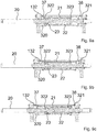
- the synchronous overstroke of the inner cylinder 22 and the piston 23 corresponds to the steps of Figures 9a, 9b and 9c , which show the passage from a first position in which the piston 23 is at the head 322 and the inner cylinder 22 is at the head 320 to a second position in which the piston 23 is still at the head 322 but the inner cylinder 22 abuts against its limit stop on the head 321 of the outer cylinder 21, thereby completing its movement.
- the rod 20 has had, in this construction example, a total displacement of 50 mm.
- the displacement of the piston 23 to the position as shown in Figure 9d corresponds to a switch point displacement of 115 mm, i.e. a total displacement of the stem 20 of 165 mm.
- the hydraulic cylinder 2 is mounted in the switch machine 1 in joined relation with the tie-like box module 100 by means of two coupling elements 24 attached at the ends of the hydraulic cylinder 2 and adapted to be fixed to the bottom of the switch machine 1.
- the hydraulic cylinder 2 also comprises a plurality of bars, preferably four, which couple together the two coupling elements 24 and prevent any relative translational and rotational movement of the two coupling elements 24, thereby ensuring firm fixation of the hydraulic cylinder to the switch machine 1 also during the operating steps thereof.
- two or three or more hydraulic cylinders are provided, one or more of which are designed to be alternately and specially driven for actuating a particular operating step of the switch machine 1.
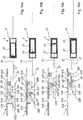
- FIGS 10a to 10d are detail views of the switch point lock means, which comprise a pair of hammers 28 and 29 supported to swing in the horizontal plane to and from the side wall 316 of the case of the tie-like box module 100 and a slider 27 driven by the pulling rod 144.
- the hammers 28 and 29 have two opposed latching lugs 128 and 228, 129 and 229, projecting out of the two opposed sides, i.e. facing toward the side wall 316 of the point pulling and locking modules 30 and 31 and the slider 27.
- One of the two opposed lugs 128, 129 cooperates with an associated latching recess 516, 616, formed in the corresponding vertical wall 316 of the point pulling and locking modules 30 and 31, for primary and secondary switch point locking actions.
- the other of the two opposed lugs 228, 229 of the two hammers 28 and 29 cooperates with an associated abutment surface 227, 327 on the slider 27 to cause the slider 27 to pull or push the hammers 29 and 29 for coupling.
- the slider 27 has a roller 39 on the side facing toward the hammers 29, 29, which adheres against a cam surface formed on an extension of said hammers 28, 29 and controls displacement thereof.
- the hammers 28, 29 have a T shape, in which the two halves of the transverse stem form the opposed lugs 128, 129 and 228, 229, whereas the base stem 328, 329 is shaped like a cam on the side facing toward the slider 27 and cooperates with the roller 39 carried thereby.
- the T-shaped hammers 28, 29 are pivoted about a vertical axis at the end of the base stem 328, 329, which extends to a certain extent beyond the fulcrum in such a manner that the roller 39 cooperating with the cam track on said end portion of the base stem 329 beyond the fulcrum, may cause the hammers to swing toward the slider 27 and to a condition of disengagement thereof from the latching recesses 516, 616 in the side wall 316 of the tie-like box module 100.
- the shape of the cam track on the base stems 328 and 329 of the hammers 28 and 29, formed by the side surfaces of said base stems facing toward the slider 27, the overall length of the two opposed lugs 128, 228 and 129, 229 and the inclination of the end sides are selected in such a manner that, when the hammers 28, 29 are in either engagement position, with the wall 316 or the slider 27, the other end surface of the opposed lug extends in a position of non-interference with the slider 27 or the wall 316.
- the base stems have a widening shape toward the fulcrum end, with two divergent opposed edge portions, whereas the edge facing toward the slider 27 and the control roller 39 is inwardly inclined substantially level with the diameter that cuts the pivot or fulcrum hole along a bisector of the angle formed by the divergent stem edge portion.
- the slider 27 may move to a certain extent in the direction of arrow D until the lug 229 of the hammer 29 cooperates with the abutment surface 327 of the slider 27. In this condition the slider 27 starts to exert a pulling force on the point operating rod on which the hammers 28 and 29 are pivotally fixed.
- the roller 39 rolls along the cam-like edge of the base stem 328 of the hammer 28 and the cam-like edge of the base stem 329 of the hammer 29, and reaches an intermediate position therebetween, i.e. a position in which it adheres to the end portions of both base stems of the hammers 28, 29, thereby causing them to simultaneously swing to disengagement of the two hammers 28 and 29 from the recesses 516, 616 in the wall 316.
- the switch point locking and pulling module associated with the opposite point performs a reverse movement, according to the same principles.
- the hydraulic cylinder 2 exerts said first predetermined actuation force.
- the slider 27 associated with the point runs its point shifting actuation stroke towards the thrown/open position of the point relative to the rail, from the position of Figure 10b to the position of Figure 10c .
- the hydraulic cylinder 2 exerts said second predetermined actuation force.
- the further final actuation overstroke will carry the hammer 29 from the abutment position against the abutment surface 227 of the slider 27, associated with the switch point 2, to the position of engagement of the lug 129 of the hammer 29 in the engagement recess 616.
- the hydraulic cylinder 2 exerts said third predetermined actuation force.
- Two of said first predetermined actuation force, said second predetermined actuation force and said third predetermined actuation force are equal to each other and different from the other actuation force.
- the first predetermined actuation force is greater than the second predetermined actuation force and the third predetermined actuation force.
- first predetermined force is exerted by the displacement of the inner cylinder 22 within the outer cylinder from a first end position to a second end position, i.e. from the position of Figure 10a to the position of Figure 10b
- second predetermined force and the third predetermined actuation force which are equal, are exerted by the displacement of the piston 23 within said inner cylinder from a first end position to a second end position, as shown in Figures 10b, 10c and 10d .
- the switch machine as shown in Figures 1 to 4 comprises a housing case for the operating units, which is preferably made of metal, particularly a tie-like box module 100, has the same size as a tie, and is adapted to be installed like a tie, and has a covering on at least part of the case, which covering consists of a material having railway ballast interface surface characteristics similar to concrete.
- the material is an epoxy resin filled with ceramic beads and has a hardness ranging from 60 to 100 Shore, preferably from 70 to 85 Shore, particularly of 75 Shore.
- the material has a thickness ranging from 2 to 10 mm, preferably from 4 to 8 mm, preferably of 6 mm.
- Such material is applied to said outer surface of the case by manual and/or automatic spreading.
- This material has superior abrasion resistance properties and is not subject to shrinkage with time.
- the material may be applied to the outer surface of the case by embedment, i.e. by placing said case in a negative mold that has an inner mold surface mating with said outer surface of the case, said negative mold being previously filled with said material in a fluid phase.
- switch machine 1 also applies to general ties: not only to switch machines, but also to hollow ties, preferably made of metal, for any wayside unit or part of the railway line or the like.
Landscapes
- Engineering & Computer Science (AREA)
- Mechanical Engineering (AREA)
- Architecture (AREA)
- Civil Engineering (AREA)
- Structural Engineering (AREA)
- Railway Tracks (AREA)
- Train Traffic Observation, Control, And Security (AREA)
- Actuator (AREA)
- Push-Button Switches (AREA)
- Injection Moulding Of Plastics Or The Like (AREA)
Description
- The invention relates to a switch machine, according to the preamble of
claim 1, for railway and tramway switches or the like, having a housing case for its operating units of the same size as a tie and adapted to be installed like a tie. - Switch machines of this type are known, for example from
EP1594732B1 , and widely used and generally comprise a metal case, e.g. formed by iron casting or structural steelwork, with sheet bending, welding, etc. - Prior art switch machines of this type usually have a protective coating, consisting of plain paint.
- Such switch machines have the drawback of having railway ballast interface surface characteristics that cause ballast to tend to move due to the vibrations induced by running trains.
- This is due to the surface characteristics of the metal material, which are actually unchanged by painting and cause the switch machine to have a very different behavior from wooden or concrete ties.
- When these switch machines remain in operating conditions for a long time, the ballast may be significantly displaced and create gaps below and around the switch machine, thereby affecting rail stability and support, and requiring earthing up of the ballast.
- The present invention has the purpose of obviating the above drawbacks of prior art switch machines with a switch machine as described above, whose outer surface further has a covering on at least part of the case, which covering consists of a material, comprising an epoxy resin, having railway ballast interface surface characteristics similar to concrete.
- Particularly, said surface characteristics are roughness, friction coefficient and hardness.
- In one embodiment, said material has a hardness ranging from 60 to 100 Shore, preferably from 70 to 85 Shore, particularly of 75 Shore.
- In a further example, said epoxy resin is filled with ceramic beads.
- In yet another example, said material has a thickness ranging from 2 to 10 mm, preferably from 4 to 8 mm, preferably of 6 mm.
- The covering with the above mentioned properties imparts concrete-like ballast interface characteristics and overcomes the above mentioned ballast displacement problems.
- Also, the covering ensures an excellent protection of the switch machine, so that the expected life of the switch machine may be increased to 30 years.
- The covering may be applied to the outer surface of the case in any manner whatever.
- Particularly, in a first example, said material is applied to said outer covering surface by manual and/or automatic spreading.
- In a further embodiment, said material is applied to said outer surface of the case by embedment, i.e. by placing said case in a negative mold that has an inner mold surface mating with said outer surface of the case, said negative mold being previously filled with said material in a fluid phase.
- Such second application method is particularly advantageous in many applications, in which the construction of molds is economically supported by great numbers of uses thereof.
- These and other features and advantages of the invention will be more apparent from the following description of a few embodiments shown in the accompanying drawings, in which:
-
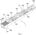
Fig. 1 is a general view of an exemplary switch machine of the present invention; -
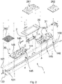
Fig. 2 is an exploded view of the switch machine in which the various components are shown; -
Fig. 3 is partially sectional side view of the switch machine; -
Fig. 4 is a top view of the switch machine; -
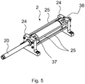
Fig. 5 is a general view of an exemplary actuator; -
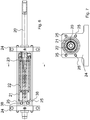
Fig. 6 is an axially sectional view of the actuator; -
Fig. 7 is a cross sectional view of the actuator; -
Fig. 8 is a detail view of the actuator; -
Figs. 9a, 9b, 9c ,9d and 9e show the various operating steps of the actuator; -
Figures 10a to 10d show the various operating steps of the switch machine. -
Figures 1 to 4 show theswitch machine 1, which comprises a switch point shifting actuator, particularly ahydraulic cylinder 2. - The
actuator 2 displaces the points, using actuation drive means, between two limit positions, one of which positions is called normal position and the other of said two positions is called reverse position, and in which positions each of the two points is thrown or open relative to the closest rail, in alternation with the other point. - The shifting stroke of the points between said two positions having a predetermined length, matches a given actuation stroke of the
actuator 2. - Lock/unlock means are further provided for locking/unlocking said points in one of said limit positions, referred to as switch point lock means, which switch point lock means are driven into their unlocking state by said
actuator 2, through an initial actuation overstroke, whose end coincides with the point unlocked state, and with the time at which said point shifting actuation stroke starts, whereas the end of the point shifting actuation stroke, in which one of the points is moved from an open position to a thrown position relative to the closest rail and the other point is moved from a thrown position to an open position relative to the closest rail, coincides with the time at which a final actuation overstroke, through which saidactuator 2 drives said point locking means into their locking state. - The
switch machine 1 and at least theactuator 2 and said actuation drive means and at least said switch point lock means have a modular construction. - Said switch point lock means consist of two point pulling and
locking modules hydraulic cylinder 2. - Each point pulling and locking module has its own case or frame, which case or frame has means for fastening it in predetermined positions, cooperating with coincident fastener means, in predetermined positions on the tie-
like box module 100 in which theswitch machine 1 is housed. - The tie-
like box module 100 consists of a C or Ω-shaped section, open at its top as a channel and closed by one or more covers. - Particularly, the tie-
like box module 100 has laterallongitudinal fins 101 having holes in predetermined positions for receiving cover elements and/or lateral flanges for fastening operating modules such as the point pulling andlocking modules - The point pulling and
locking modules like box module 100 and are mounted in a predetermined position with reference to the tie-like box module using fastener means. - The ends of the channel section are closed by
end heads 130 that may also be removably fastened or possibly welded. - A portion of the cover of the tie-
like box module 100 is formed by the upper cover of the modules, whereas the portions of the tie-like box module 100 that are open at their top as they are not filled by operating units are closed by a plurality of cover elements having the same size as said open or exposed parts. Such cover elements are referenced 260, 261 and 262. - One end of the
switch machine 1 is designed for connection with fluid supply lines and/or power lines for any electronic diagnostic system or the like. - Each of the point pulling and
locking modules pulling rod 144 which is dynamically connected to pullingsliders 145 that project out of anupper fastening plate 146. Thefastening plate 146 has lateral holes for fixation to the laterallongitudinal fins 101 of the tie-like box module 100 and also forms the closing cover of said tie-like box module 100 when the pulling and locking module is mounted to the tie-like box module itself. Thepulling sliders 145 have a positive geometry mating with the negative seat in the brackets for connection to the points. - The
pulling rod 144 has a removable terminal for connection to theactuator 2 or to further actuation drive means. - Means are further provided for adjusting the actuation stroke exerted by the
actuator 2, which operate to cause theactuator 2 to exert a first predetermined actuation force during the initial actuation overstroke to unlock said point switch lock means, a second predetermined actuation force during said point shifting actuation stroke and a third predetermined actuation stroke during the final actuation overstroke to lock the point lock means. - The
actuator 2 may consist of any kind of motor, such as an electric motor and a kinematic drive chain, which kinematic drive chain may be of any type and consist, for instance, of a screw-and-nut or recirculating-ball assembly. - In this case, the actuation force exerted by the
actuator 2 may be controlled by setting the force to be generated by the motor. In an alternative configuration, said kinematic drive chain may change the drive ratio according to the stroke that has been run: a first drive ratio is used for the initial actuation overstroke, a second drive ratio is used for the point shifting actuation stroke, and a third drive ratio is used for the final actuation overstroke. - In the illustrated example, the
actuator 2 is a hydraulic actuator, particularly ahydraulic cylinder 2, which is connected to at least one delivery branch and at least one return branch of a closed hydraulic fluid circulation circuit. - In one example, the means for adjusting the actuation force exerted by the
actuator 2 consist of means for setting the fluid delivery to theactuator 2, particularly comprising at least one adjustable flow pump. - The pump may be a positive-displacement pump controlled at a variable speed and having a predetermined fixed displacement.
- As used herein, the term positive-displacement pump is intended to designate a pump having a suction/compression chamber of predetermined volume, which changes fluid delivery according to the speed of actuation of a suction/compression member. A particular positive-displacement pump is the piston or gear pump. In this case, the volume of pressure fluid that can be delivered per unit of time is determined by the displacement and number of suction/compression strokes of the piston. Nevertheless, other types of pumps may be considered as positive-displacement pumps according to the definition as used herein, such as rotor pumps and/or pumps having suction/compression members based on the Wankel engine principle, in which the suction/compression chamber has a fixed and predetermined volume.
- Alternatively, two or three or more pumps with different displacements may be provided, one or more of which are designed to be alternately and specially driven for actuating a particular operating step of the
switch machine 1. The use of multiple positive-displacement pumps is generally disclosed inEP 2192020 . - In the example as particularly shown in
Figures 5 to 10d , said force adjustment means consist of theactuator 2 itself. - The
actuator 2 consists of ahydraulic cylinder 2 which comprises at least one pushing or pullingrod 20 adapted to be connected to one or both of said points and to be displaced from a minimum-extension position to a maximum-extension position. - Particularly, the
hydraulic cylinder 2 is a double acting cylinder, having two supply inlets, each of said supply inlets being adapted to be alternately connected to the delivery of the fluid circuit. - The
rod 20 extends beyond both end walls of thehydraulic cylinder 20 and can be displaced from a position in which one part is in the minimum-extension state and the opposite part is in the maximum-extension state to a position in which the first part is in the maximum-extension state and the opposite part is in the minimum-extension state. - The ends of the
rod 20 are removably connected to thepulling rods 144 of the point pulling andlocking modules - The displacement of the
rod 20 drives the initial actuation overstroke, the point shifting actuation stroke and the final actuation overstroke, as shown inFigures 10a to 10d . - The
hydraulic cylinder 2 is so designed that, given a pressure of the fluid, it exerts said first predetermined actuation force along the length of displacement of therod 20 that corresponds to the initial actuation overstroke, said second predetermined actuation force along the length of displacement of therod 20 that corresponds to the point shifting actuation stroke, and said third predetermined actuation force along the length of displacement of therod 20 that corresponds to the final actuation overstroke. - As clearly shown in
Figures 6 and 7 , thehydraulic cylinder 2 comprises anouter cylinder 21 and aninner cylinder 22, the outside diameter of theinner cylinder 22 being substantially equal to the inside diameter of theouter cylinder 21, the height of theinner cylinder 22 being smaller than the height of theouter cylinder 21 and theinner cylinder 22 being disposed coaxially inside theouter cylinder 21. - Thus, the
inner cylinder 22 is displaceable in a fluid-tight manner in theouter cylinder 21 between two end positions defined by the inner extension of theouter cylinder 21. - A
piston 23 is further provided in the inner cylinder, which is connected to therod 20 and is displaceable between two end positions defined by the inner extension of theinner cylinder 22. - The
rod 20 is adapted to extend through openings formed in the head surfaces of theinner cylinder 22 and the head surfaces of theouter cylinder 21. - In one example, the
piston 23 has a fluid-tight connection with theinner cylinder 22 which in turn has a fluid-tight connection with theouter cylinder 21. - The
piston 23 is coupled to therod 20 in a central position thereof, to define two opposite parts of therod 20, which extend through theheads inner cylinder 22 and are guided in a fluid-tight manner in theheads outer cylinder 21. - The passage from the inner cylinder to the delivery or return of the
actuator 2 may occur in various manners. - Referring to
Figures 6 to 9e , such passage particularly occurs through radial fluid supply/discharge openings orpassages heads - In the illustrated embodiment, the cylinder has two fluid supply/
discharge openings 37 formed in thefirst head 320, and two fluid supply/discharge openings 38 formed in thesecond head 321, to be used if multiple actuators are connected in parallel, so that, for instance, during fluid supply, the fluid coming from an upstream actuator in the supply line enters a first opening and exits a second opening to supply a downstream actuator in the supply line. Thus, the pressure fluid is delivered to all the actuators. The same principle applies to the fluid outlet of the cylinder. - In the same case of parallel supply of multiple actuators, a single fluid supply/
discharge opening 37 and single fluid supply/discharge opening 38 may be also alternatively provided, with the provision of T-fittings to create parallel supply branches for eachactuator 2. - The fluid supply/
discharge openings 37 communicate with aradial opening 132 in thehead 320, which is designed to communicate with the interior of theouter cylinder 22 through anannular slot 33 between the throughrod 20 and thehead 320. - An
annular slot 34 is also provided between thehead 322 and therod 34, to put the chamber of theouter cylinder 21 in communication with the chamber of theinner cylinder 22. - The cylinder has the same structural parts in the opposite part, at the
head 321. - In an initial limit position, the
head 322 abuts against the correspondinghead 320 and thepiston 23 is at thehead 322. - Upon delivery, the supply fluid flows through the
radial opening 132 and through theannular slot 33 thereby causing a pressure increase. - Due to such initial pressure increase, the fluid exerts a force on the
head surface 322 of theinner cylinder 22 facing toward the chamber of theouter cylinder 21, which force is greater than the force exerted on thepiston 23 through theannular slot 34, as thehead surface 322 of theinner cylinder 22 facing toward the chamber of theouter cylinder 21 is much larger than the surface of thepiston 23 available to the fluid through theannular slot 34. - Thus, the fluid starts to fill the chamber of the
outer cylinder 21, thereby pushing theinner cylinder 22 and hence thepiston 23 toward theopposite head 321. - The
inner cylinder 22 and thepiston 23 are held in joined relation as they move by the limit stop abutment for thepiston 23 on thehead 322. - Once the inner cylinder abuts against the
head 321, the pressure fluid starts to move thepiston 23 in theinner cylinder 22 toward thehead 323, thereby progressively filling the chamber of theinner cylinder 22 by flowing through theannular slot 34. - The fluid contained in the cylinder when such movement starts is simultaneously ejected from the return camber through the
radial opening 132 that is also provided in thehead 321. - The return occurs with much the same process as described above, except that the delivery and the
discharge piston 23 and therod 20 are pushed in an opposite direction. The movement and the parts that cause it is as described above concerning displacement in a first direction. - The various displacement steps are as shown in detail in
Figures 9a to 9e . - The synchronous overstroke of the
inner cylinder 22 and thepiston 23 corresponds to the steps ofFigures 9a, 9b and 9c , which show the passage from a first position in which thepiston 23 is at thehead 322 and theinner cylinder 22 is at thehead 320 to a second position in which thepiston 23 is still at thehead 322 but theinner cylinder 22 abuts against its limit stop on thehead 321 of theouter cylinder 21, thereby completing its movement. - In this condition, the
rod 20 has had, in this construction example, a total displacement of 50 mm. - The further flow of fluid through the
passage 132 of thehead 320 acts upon thepiston 23. - The displacement of the
piston 23 to the position as shown inFigure 9d corresponds to a switch point displacement of 115 mm, i.e. a total displacement of thestem 20 of 165 mm. - Further displacement of the
piston 23 occurs in the overstroke step for locking the switch point lock members of theactuator 2 and takes a further 50 mm distance to abutment on thehead 323 of theinner cylinder 22, with 215 mm displacement of thestem 20 in total. Thehydraulic cylinder 2 is mounted in theswitch machine 1 in joined relation with the tie-like box module 100 by means of twocoupling elements 24 attached at the ends of thehydraulic cylinder 2 and adapted to be fixed to the bottom of theswitch machine 1. - The
hydraulic cylinder 2 also comprises a plurality of bars, preferably four, which couple together the twocoupling elements 24 and prevent any relative translational and rotational movement of the twocoupling elements 24, thereby ensuring firm fixation of the hydraulic cylinder to theswitch machine 1 also during the operating steps thereof. - In an alternative example, not shown, two or three or more hydraulic cylinders are provided, one or more of which are designed to be alternately and specially driven for actuating a particular operating step of the
switch machine 1. - The operation of the switch machine of the invention is illustrated in detail in the example of
Figures 10a, 10b, 10c and 10d , in which various performances of thehydraulic cylinder 2 are calibrated according to the actuation steps of theswitch machine 1, as different steps require different forces or pressures, that must be properly exerted to avoid synchronization problems in point shifting along the switch, where many actuators are provided. -
Figures 10a to 10d are detail views of the switch point lock means, which comprise a pair ofhammers side wall 316 of the case of the tie-like box module 100 and aslider 27 driven by the pullingrod 144. - The
hammers side wall 316 of the point pulling and lockingmodules slider 27. - One of the two
opposed lugs latching recess vertical wall 316 of the point pulling and lockingmodules - The other of the two
opposed lugs hammers abutment surface slider 27 to cause theslider 27 to pull or push thehammers - The
slider 27 has aroller 39 on the side facing toward thehammers hammers opposed lugs base stem slider 27 and cooperates with theroller 39 carried thereby. - The T-shaped
hammers base stem roller 39 cooperating with the cam track on said end portion of thebase stem 329 beyond the fulcrum, may cause the hammers to swing toward theslider 27 and to a condition of disengagement thereof from the latching recesses 516, 616 in theside wall 316 of the tie-like box module 100. - Particularly, the shape of the cam track on the base stems 328 and 329 of the
hammers slider 27, the overall length of the twoopposed lugs hammers wall 316 or theslider 27, the other end surface of the opposed lug extends in a position of non-interference with theslider 27 or thewall 316. - The base stems have a widening shape toward the fulcrum end, with two divergent opposed edge portions, whereas the edge facing toward the
slider 27 and thecontrol roller 39 is inwardly inclined substantially level with the diameter that cuts the pivot or fulcrum hole along a bisector of the angle formed by the divergent stem edge portion. - The
slider 27 may move to a certain extent in the direction of arrow D until thelug 229 of thehammer 29 cooperates with theabutment surface 327 of theslider 27. In this condition theslider 27 starts to exert a pulling force on the point operating rod on which thehammers - During the initial free stroke of the
slider 27, whose start is shown infigure 10a and whose end is shown inFigure 10b , i.e. during the initial actuation overstroke, theroller 39 rolls along the cam-like edge of thebase stem 328 of thehammer 28 and the cam-like edge of thebase stem 329 of thehammer 29, and reaches an intermediate position therebetween, i.e. a position in which it adheres to the end portions of both base stems of thehammers hammers recesses wall 316. Obviously, the switch point locking and pulling module associated with the opposite point performs a reverse movement, according to the same principles. - In this step, the
hydraulic cylinder 2 exerts said first predetermined actuation force. - Therefore, the
slider 27 associated with the point runs its point shifting actuation stroke towards the thrown/open position of the point relative to the rail, from the position ofFigure 10b to the position ofFigure 10c . - The thrown position of a first point relative to the rail, and the open position of the opposite point relative to the opposite rail, as shown in
Figure 10b , is reached before the end of the displacement stroke of the pullingrod 144. - In this step, the
hydraulic cylinder 2 exerts said second predetermined actuation force. - The further final actuation overstroke will carry the
hammer 29 from the abutment position against theabutment surface 227 of theslider 27, associated with theswitch point 2, to the position of engagement of thelug 129 of thehammer 29 in theengagement recess 616. - In this step, the
hydraulic cylinder 2 exerts said third predetermined actuation force. - Two of said first predetermined actuation force, said second predetermined actuation force and said third predetermined actuation force are equal to each other and different from the other actuation force.
- Particularly, in the illustrated example, the first predetermined actuation force is greater than the second predetermined actuation force and the third predetermined actuation force.
- This is ensured because the first predetermined force is exerted by the displacement of the
inner cylinder 22 within the outer cylinder from a first end position to a second end position, i.e. from the position ofFigure 10a to the position ofFigure 10b , and the second predetermined force and the third predetermined actuation force, which are equal, are exerted by the displacement of thepiston 23 within said inner cylinder from a first end position to a second end position, as shown inFigures 10b, 10c and 10d . - The switch machine as shown in
Figures 1 to 4 comprises a housing case for the operating units, which is preferably made of metal, particularly a tie-like box module 100, has the same size as a tie, and is adapted to be installed like a tie, and has a covering on at least part of the case, which covering consists of a material having railway ballast interface surface characteristics similar to concrete. - The material is an epoxy resin filled with ceramic beads and has a hardness ranging from 60 to 100 Shore, preferably from 70 to 85 Shore, particularly of 75 Shore.
- Advantageously, the material has a thickness ranging from 2 to 10 mm, preferably from 4 to 8 mm, preferably of 6 mm.
- Such material is applied to said outer surface of the case by manual and/or automatic spreading.
- Since epoxy resins mainly have a mechanical rather than chemical adhesion, or holding power, predetermined sanding is required to prepare the surface of the tie-
like box module 100 before application of the resin. - This material has superior abrasion resistance properties and is not subject to shrinkage with time.
- As an alternative, the material may be applied to the outer surface of the case by embedment, i.e. by placing said case in a negative mold that has an inner mold surface mating with said outer surface of the case, said negative mold being previously filled with said material in a fluid phase.
- The above description of the
switch machine 1 also applies to general ties: not only to switch machines, but also to hollow ties, preferably made of metal, for any wayside unit or part of the railway line or the like.
Claims (6)
- A switch machine (1) for railway and tramway switches or the like, of the type comprising operating units housed in a case,
wherein
the operating units include a switch point shifting actuator (2), the actuator being configured for displacing points, using actuation drive means, in use, between two limit positions, and lock/unlock means for locking/unlocking said points in one of said limit positions, lock/unlock means being located at the opposite ends of said actuator, the actuator being housed in the case and the lock/unlock means being fastened on the case,
the case being a box module (100) of the same size as a tie and adapted to be installed like a tie,
characterized in that the outer surface of the switch machine (1) has a covering (260, 261, 262) on at least part of the case, which covering consists of materials having roughness, friction coefficient and hardness similar to concrete, such materials comprising an epoxy resin. - A switch machine (1) as claimed in claim 1, wherein said material has a hardness ranging from 60 to 100 Shore, preferably from 70 to 85 Shore, particularly of 75 Shore.
- A switch machine (1) as claimed in claim 1 or 2, wherein said epoxy resin is filled with ceramic beads.
- A switch machine (1) as claimed in one or more of claims 1 to 3, wherein said material has a thickness ranging from 2 to 10 mm, preferably from 4 to 8 mm, preferably of 6 mm.
- A method for making a switch machine (1) for railway and tramway switches or the like, of the type comprising operating units housed in a tie-like box module (100), the operating units including a switch point shifting actuator (2), the actuator being configured for displacing points, using actuation drive means, between two limit positions, and lock/unlock means for locking/unlocking said points in one of said limit positions, lock/unlock means being located at the opposite ends of said actuator, the actuator being housed in the box module and the lock/unlock means being fastened on the box module, the outer surface of the said switch machine (1) having a covering (260, 261, 262) on at least part of the box module, characterized in applying an epoxy resin to said outer surface of the case by manual and/or automatic spreading.
- A method as claimed in claim 5, wherein said epoxy resin is applied to said outer surface of the switch machine (1) by placing said switch machine (1) in a negative mold that has an inner mold surface mating with said outer surface of the switch machine (1), said negative mold being previously filled with said epoxy resin in a fluid phase.
Priority Applications (2)
| Application Number | Priority Date | Filing Date | Title |
|---|---|---|---|
| PL15175255T PL2960134T3 (en) | 2011-08-30 | 2011-08-30 | Switch machine for railway and tramway switches or the like |
| EP15175255.7A EP2960134B1 (en) | 2011-08-30 | 2011-08-30 | Switch machine for railway and tramway switches or the like |
Applications Claiming Priority (2)
| Application Number | Priority Date | Filing Date | Title |
|---|---|---|---|
| EP11179434.3A EP2565099B1 (en) | 2011-08-30 | 2011-08-30 | Railway switch |
| EP15175255.7A EP2960134B1 (en) | 2011-08-30 | 2011-08-30 | Switch machine for railway and tramway switches or the like |
Related Parent Applications (2)
| Application Number | Title | Priority Date | Filing Date |
|---|---|---|---|
| EP11179434.3A Division EP2565099B1 (en) | 2011-08-30 | 2011-08-30 | Railway switch |
| EP11179434.3A Division-Into EP2565099B1 (en) | 2011-08-30 | 2011-08-30 | Railway switch |
Publications (2)
| Publication Number | Publication Date |
|---|---|
| EP2960134A1 EP2960134A1 (en) | 2015-12-30 |
| EP2960134B1 true EP2960134B1 (en) | 2020-02-05 |
Family
ID=44905369
Family Applications (2)
| Application Number | Title | Priority Date | Filing Date |
|---|---|---|---|
| EP15175255.7A Active EP2960134B1 (en) | 2011-08-30 | 2011-08-30 | Switch machine for railway and tramway switches or the like |
| EP11179434.3A Active EP2565099B1 (en) | 2011-08-30 | 2011-08-30 | Railway switch |
Family Applications After (1)
| Application Number | Title | Priority Date | Filing Date |
|---|---|---|---|
| EP11179434.3A Active EP2565099B1 (en) | 2011-08-30 | 2011-08-30 | Railway switch |
Country Status (3)
| Country | Link |
|---|---|
| EP (2) | EP2960134B1 (en) |
| AU (2) | AU2012211515B2 (en) |
| PL (1) | PL2960134T3 (en) |
Families Citing this family (5)
| Publication number | Priority date | Publication date | Assignee | Title |
|---|---|---|---|---|
| FR3059620B1 (en) * | 2016-12-01 | 2019-08-30 | Vossloh Cogifer | DEVICE FOR MANEUVERING FOR NEEDLE |
| CN107953900A (en) * | 2017-12-08 | 2018-04-24 | 张伟钢 | The application method and goat protective cover and goat of goat protective cover |
| CN109823368B (en) * | 2019-02-23 | 2023-12-19 | 西安天宝信号技术有限公司 | Integrated transmission locking mechanism for switch machine |
| CN113447291B (en) * | 2021-06-28 | 2022-05-24 | 西安铁路信号有限责任公司 | Method for detecting slipping of friction coupler of point switch or overflow of overflow valve |
| DE102022210176A1 (en) | 2022-09-27 | 2024-03-28 | Siemens Mobility GmbH | Point drive with variably adjustable adjusting slide |
Family Cites Families (13)
| Publication number | Priority date | Publication date | Assignee | Title |
|---|---|---|---|---|
| SE506183C2 (en) * | 1993-05-27 | 1997-11-17 | Abb Daimler Benz Transp | Device at railroad tracks for the change of track gear |
| EP0796777A1 (en) * | 1996-03-23 | 1997-09-24 | Alcatel Austria Aktiengesellschaft | Operating device for railway switch |
| IT1298019B1 (en) * | 1997-10-22 | 1999-12-20 | Sasib Railway Spa | CASE OF OPERATION FOR RAILWAY, RAILWAY, OR SIMILAR EXCHANGES. |
| NL1014443C1 (en) * | 1999-02-19 | 2000-08-22 | Kloos Oving B V | Self-sealing plate for mechanical switching mechanism used on railway points, prevents ingress of leaves or other objects |
| WO2000073119A1 (en) * | 1999-06-01 | 2000-12-07 | Horváth, József | Driving gear for points |
| ITSV20000062A1 (en) | 2000-12-28 | 2002-06-28 | Alstom Transp Spa | CASE OF MANEUVERING FOR RAILWAY OR SIMILAR DEVIATORS WITH ANTI-TALLONING DEVICE OF CONTRAST TO THE HEELING OF THE SWITCH NEEDLES |
| AT411047B (en) * | 2001-01-11 | 2003-09-25 | Vae Eisenbahnsysteme Gmbh | DEVICE FOR LOCKING THE END OF MOVING PARTS |
| NL1017746C2 (en) * | 2001-03-30 | 2002-10-07 | Wisselbouw Nederland B V | Rail track points housing comprises hollow, elongated component with lower wall, horizontal upper wall and two transversally extending upright side walls, upper wall being provided with one or more recesses |
| ITSV20030006A1 (en) * | 2003-02-18 | 2004-08-19 | Alstom Transp Spa | CASE OF OPERATION FOR TRAVELING OR SIMILAR RAILWAY DIVERTERS. |
| JP2008069526A (en) * | 2006-09-13 | 2008-03-27 | Sekisui Chem Co Ltd | Sleeper for railroad |
| US20080093507A1 (en) * | 2006-10-24 | 2008-04-24 | Union Switch & Signal, Inc. | Concrete tie |
| ES2373806T3 (en) | 2008-11-27 | 2012-02-08 | Alstom Transport Sa | DEVICE FOR THE DISPLACEMENT OF THE POINTS OF THE HANDS OF CHANGE OF THE VIA FÉRREA, ESPECIALLY OF THE HIGH SPEEDS AND THE PROCEDURE FOR THE DISPLACEMENT OF THE HANDS OF CHANGE OF THE WAY. |
| ES2361873B1 (en) * | 2009-03-06 | 2012-05-07 | Administrador De Infraestructuras Ferroviarias (Adif) | COVERAGE COVER OF MECHANISMS IN CROSS DRAWER OF VARIOUS EQUIPMENT AND MANUFACTURING SYSTEM OF THE SAME. |
-
2011
- 2011-08-30 EP EP15175255.7A patent/EP2960134B1/en active Active
- 2011-08-30 PL PL15175255T patent/PL2960134T3/en unknown
- 2011-08-30 EP EP11179434.3A patent/EP2565099B1/en active Active
-
2012
- 2012-08-13 AU AU2012211515A patent/AU2012211515B2/en active Active
-
2017
- 2017-01-12 AU AU2017200214A patent/AU2017200214B9/en active Active
Non-Patent Citations (1)
| Title |
|---|
| None * |
Also Published As
| Publication number | Publication date |
|---|---|
| EP2960134A1 (en) | 2015-12-30 |
| PL2960134T3 (en) | 2020-11-16 |
| AU2012211515B2 (en) | 2017-09-14 |
| AU2012211515A1 (en) | 2013-03-21 |
| EP2565099A3 (en) | 2014-08-06 |
| EP2565099B1 (en) | 2017-11-29 |
| EP2565099A1 (en) | 2013-03-06 |
| AU2017200214B9 (en) | 2018-11-22 |
| AU2017200214B2 (en) | 2018-11-15 |
| AU2017200214A1 (en) | 2017-02-02 |
Similar Documents
| Publication | Publication Date | Title |
|---|---|---|
| AU2017200214B9 (en) | Switch machine for railway and tramway switches or the like | |
| CN109531771B (en) | Equipment and method for preparing building structure based on 3D printing | |
| US8291871B2 (en) | Ball-lift compression ratio adjustment device for a variable compression ratio engine | |
| EP2217099B1 (en) | Cam apparatus for valve stem actuation | |
| KR20100051058A (en) | Self-contained hydraulic actuator system | |
| CN109531772B (en) | Equipment and method for preparing building structure based on 3D printing | |
| US8439004B2 (en) | Ball-lift device with screw for a variable compression ratio engine | |
| CN106945242A (en) | A kind of double-plate clamping apparatus | |
| CN102823120A (en) | Linear power generator | |
| CN1130892A (en) | Device for changing points | |
| CN101594946A (en) | Die cushion device with hybrid drive | |
| CN102395437B (en) | Drive device of a regulation valve for casting liquid metal | |
| CN109531770B (en) | Equipment and method for preparing building structure based on 3D printing | |
| ITMI20130377A1 (en) | VALVE FOR FORMWORK AND FORMWORK PROVIDED WITH THIS VALVE | |
| EP2192020A1 (en) | Device for moving railroad switch points, particulary high-speed ones and method for moving railroad switch points | |
| CN206589297U (en) | A kind of double-plate clamping apparatus | |
| EP2820299A1 (en) | Liquid piston arrangement with a plate-type heat exchanger for the quasi isothermal compression and expansion of gases | |
| CN206598496U (en) | A kind of band-type brake component and double-plate clamping apparatus | |
| CN106827429A (en) | A kind of band-type brake component and double-plate clamping apparatus | |
| CN103538224B (en) | A kind of mold closing mechanism of two plate direct press type injection moulding machines | |
| KR101199257B1 (en) | Electric-hydraulic hybrid actuator | |
| SE1050117A1 (en) | Method and apparatus for producing a drainage element and thereby producing a drainage element | |
| KR20140010086A (en) | Arrangement for receiving a casting mould with coaxial drive and method therefor | |
| CN219360218U (en) | Injection mold with sliding block embedded shaft structure | |
| CN213703176U (en) | Slide valve assembling tool |
Legal Events
| Date | Code | Title | Description |
|---|---|---|---|
| PUAI | Public reference made under article 153(3) epc to a published international application that has entered the european phase |
Free format text: ORIGINAL CODE: 0009012 |
|
| AC | Divisional application: reference to earlier application |
Ref document number: 2565099 Country of ref document: EP Kind code of ref document: P |
|
| AK | Designated contracting states |
Kind code of ref document: A1 Designated state(s): AL AT BE BG CH CY CZ DE DK EE ES FI FR GB GR HR HU IE IS IT LI LT LU LV MC MK MT NL NO PL PT RO RS SE SI SK SM TR |
|
| 17P | Request for examination filed |
Effective date: 20160630 |
|
| RBV | Designated contracting states (corrected) |
Designated state(s): AL AT BE BG CH CY CZ DE DK EE ES FI FR GB GR HR HU IE IS IT LI LT LU LV MC MK MT NL NO PL PT RO RS SE SI SK SM TR |
|
| RAP1 | Party data changed (applicant data changed or rights of an application transferred) |
Owner name: ALSTOM TRANSPORT TECHNOLOGIES |
|
| STAA | Information on the status of an ep patent application or granted ep patent |
Free format text: STATUS: EXAMINATION IS IN PROGRESS |
|
| 17Q | First examination report despatched |
Effective date: 20171215 |
|
| GRAP | Despatch of communication of intention to grant a patent |
Free format text: ORIGINAL CODE: EPIDOSNIGR1 |
|
| STAA | Information on the status of an ep patent application or granted ep patent |
Free format text: STATUS: GRANT OF PATENT IS INTENDED |
|
| INTG | Intention to grant announced |
Effective date: 20190923 |
|
| GRAS | Grant fee paid |
Free format text: ORIGINAL CODE: EPIDOSNIGR3 |
|
| GRAA | (expected) grant |
Free format text: ORIGINAL CODE: 0009210 |
|
| STAA | Information on the status of an ep patent application or granted ep patent |
Free format text: STATUS: THE PATENT HAS BEEN GRANTED |
|
| AC | Divisional application: reference to earlier application |
Ref document number: 2565099 Country of ref document: EP Kind code of ref document: P |
|
| AK | Designated contracting states |
Kind code of ref document: B1 Designated state(s): AL AT BE BG CH CY CZ DE DK EE ES FI FR GB GR HR HU IE IS IT LI LT LU LV MC MK MT NL NO PL PT RO RS SE SI SK SM TR |
|
| REG | Reference to a national code |
Ref country code: GB Ref legal event code: FG4D |
|
| REG | Reference to a national code |
Ref country code: AT Ref legal event code: REF Ref document number: 1229697 Country of ref document: AT Kind code of ref document: T Effective date: 20200215 |
|
| REG | Reference to a national code |
Ref country code: DE Ref legal event code: R096 Ref document number: 602011064869 Country of ref document: DE |
|
| REG | Reference to a national code |
Ref country code: IE Ref legal event code: FG4D |
|
| REG | Reference to a national code |
Ref country code: CH Ref legal event code: EP |
|
| REG | Reference to a national code |
Ref country code: NL Ref legal event code: FP |
|
| PG25 | Lapsed in a contracting state [announced via postgrant information from national office to epo] |
Ref country code: PT Free format text: LAPSE BECAUSE OF FAILURE TO SUBMIT A TRANSLATION OF THE DESCRIPTION OR TO PAY THE FEE WITHIN THE PRESCRIBED TIME-LIMIT Effective date: 20200628 Ref country code: NO Free format text: LAPSE BECAUSE OF FAILURE TO SUBMIT A TRANSLATION OF THE DESCRIPTION OR TO PAY THE FEE WITHIN THE PRESCRIBED TIME-LIMIT Effective date: 20200505 Ref country code: FI Free format text: LAPSE BECAUSE OF FAILURE TO SUBMIT A TRANSLATION OF THE DESCRIPTION OR TO PAY THE FEE WITHIN THE PRESCRIBED TIME-LIMIT Effective date: 20200205 Ref country code: RS Free format text: LAPSE BECAUSE OF FAILURE TO SUBMIT A TRANSLATION OF THE DESCRIPTION OR TO PAY THE FEE WITHIN THE PRESCRIBED TIME-LIMIT Effective date: 20200205 |
|
| REG | Reference to a national code |
Ref country code: LT Ref legal event code: MG4D |
|
| PG25 | Lapsed in a contracting state [announced via postgrant information from national office to epo] |
Ref country code: HR Free format text: LAPSE BECAUSE OF FAILURE TO SUBMIT A TRANSLATION OF THE DESCRIPTION OR TO PAY THE FEE WITHIN THE PRESCRIBED TIME-LIMIT Effective date: 20200205 Ref country code: GR Free format text: LAPSE BECAUSE OF FAILURE TO SUBMIT A TRANSLATION OF THE DESCRIPTION OR TO PAY THE FEE WITHIN THE PRESCRIBED TIME-LIMIT Effective date: 20200506 Ref country code: BG Free format text: LAPSE BECAUSE OF FAILURE TO SUBMIT A TRANSLATION OF THE DESCRIPTION OR TO PAY THE FEE WITHIN THE PRESCRIBED TIME-LIMIT Effective date: 20200505 Ref country code: IS Free format text: LAPSE BECAUSE OF FAILURE TO SUBMIT A TRANSLATION OF THE DESCRIPTION OR TO PAY THE FEE WITHIN THE PRESCRIBED TIME-LIMIT Effective date: 20200605 Ref country code: SE Free format text: LAPSE BECAUSE OF FAILURE TO SUBMIT A TRANSLATION OF THE DESCRIPTION OR TO PAY THE FEE WITHIN THE PRESCRIBED TIME-LIMIT Effective date: 20200205 Ref country code: LV Free format text: LAPSE BECAUSE OF FAILURE TO SUBMIT A TRANSLATION OF THE DESCRIPTION OR TO PAY THE FEE WITHIN THE PRESCRIBED TIME-LIMIT Effective date: 20200205 |
|
| PG25 | Lapsed in a contracting state [announced via postgrant information from national office to epo] |
Ref country code: ES Free format text: LAPSE BECAUSE OF FAILURE TO SUBMIT A TRANSLATION OF THE DESCRIPTION OR TO PAY THE FEE WITHIN THE PRESCRIBED TIME-LIMIT Effective date: 20200205 Ref country code: CZ Free format text: LAPSE BECAUSE OF FAILURE TO SUBMIT A TRANSLATION OF THE DESCRIPTION OR TO PAY THE FEE WITHIN THE PRESCRIBED TIME-LIMIT Effective date: 20200205 Ref country code: LT Free format text: LAPSE BECAUSE OF FAILURE TO SUBMIT A TRANSLATION OF THE DESCRIPTION OR TO PAY THE FEE WITHIN THE PRESCRIBED TIME-LIMIT Effective date: 20200205 Ref country code: DK Free format text: LAPSE BECAUSE OF FAILURE TO SUBMIT A TRANSLATION OF THE DESCRIPTION OR TO PAY THE FEE WITHIN THE PRESCRIBED TIME-LIMIT Effective date: 20200205 Ref country code: SM Free format text: LAPSE BECAUSE OF FAILURE TO SUBMIT A TRANSLATION OF THE DESCRIPTION OR TO PAY THE FEE WITHIN THE PRESCRIBED TIME-LIMIT Effective date: 20200205 Ref country code: EE Free format text: LAPSE BECAUSE OF FAILURE TO SUBMIT A TRANSLATION OF THE DESCRIPTION OR TO PAY THE FEE WITHIN THE PRESCRIBED TIME-LIMIT Effective date: 20200205 Ref country code: RO Free format text: LAPSE BECAUSE OF FAILURE TO SUBMIT A TRANSLATION OF THE DESCRIPTION OR TO PAY THE FEE WITHIN THE PRESCRIBED TIME-LIMIT Effective date: 20200205 Ref country code: SK Free format text: LAPSE BECAUSE OF FAILURE TO SUBMIT A TRANSLATION OF THE DESCRIPTION OR TO PAY THE FEE WITHIN THE PRESCRIBED TIME-LIMIT Effective date: 20200205 |
|
| REG | Reference to a national code |
Ref country code: DE Ref legal event code: R097 Ref document number: 602011064869 Country of ref document: DE |
|
| REG | Reference to a national code |
Ref country code: AT Ref legal event code: MK05 Ref document number: 1229697 Country of ref document: AT Kind code of ref document: T Effective date: 20200205 |
|
| PLBE | No opposition filed within time limit |
Free format text: ORIGINAL CODE: 0009261 |
|
| STAA | Information on the status of an ep patent application or granted ep patent |
Free format text: STATUS: NO OPPOSITION FILED WITHIN TIME LIMIT |
|
| 26N | No opposition filed |
Effective date: 20201106 |
|
| PG25 | Lapsed in a contracting state [announced via postgrant information from national office to epo] |
Ref country code: AT Free format text: LAPSE BECAUSE OF FAILURE TO SUBMIT A TRANSLATION OF THE DESCRIPTION OR TO PAY THE FEE WITHIN THE PRESCRIBED TIME-LIMIT Effective date: 20200205 |
|
| PG25 | Lapsed in a contracting state [announced via postgrant information from national office to epo] |
Ref country code: SI Free format text: LAPSE BECAUSE OF FAILURE TO SUBMIT A TRANSLATION OF THE DESCRIPTION OR TO PAY THE FEE WITHIN THE PRESCRIBED TIME-LIMIT Effective date: 20200205 |
|
| REG | Reference to a national code |
Ref country code: DE Ref legal event code: R119 Ref document number: 602011064869 Country of ref document: DE |
|
| PG25 | Lapsed in a contracting state [announced via postgrant information from national office to epo] |
Ref country code: MC Free format text: LAPSE BECAUSE OF FAILURE TO SUBMIT A TRANSLATION OF THE DESCRIPTION OR TO PAY THE FEE WITHIN THE PRESCRIBED TIME-LIMIT Effective date: 20200205 |
|
| REG | Reference to a national code |
Ref country code: CH Ref legal event code: PL |
|
| PG25 | Lapsed in a contracting state [announced via postgrant information from national office to epo] |
Ref country code: LU Free format text: LAPSE BECAUSE OF NON-PAYMENT OF DUE FEES Effective date: 20200830 Ref country code: LI Free format text: LAPSE BECAUSE OF NON-PAYMENT OF DUE FEES Effective date: 20200831 Ref country code: CH Free format text: LAPSE BECAUSE OF NON-PAYMENT OF DUE FEES Effective date: 20200831 |
|
| REG | Reference to a national code |
Ref country code: BE Ref legal event code: MM Effective date: 20200831 |
|
| PG25 | Lapsed in a contracting state [announced via postgrant information from national office to epo] |
Ref country code: DE Free format text: LAPSE BECAUSE OF NON-PAYMENT OF DUE FEES Effective date: 20210302 |
|
| PG25 | Lapsed in a contracting state [announced via postgrant information from national office to epo] |
Ref country code: BE Free format text: LAPSE BECAUSE OF NON-PAYMENT OF DUE FEES Effective date: 20200831 Ref country code: IE Free format text: LAPSE BECAUSE OF NON-PAYMENT OF DUE FEES Effective date: 20200830 |
|
| PG25 | Lapsed in a contracting state [announced via postgrant information from national office to epo] |
Ref country code: TR Free format text: LAPSE BECAUSE OF FAILURE TO SUBMIT A TRANSLATION OF THE DESCRIPTION OR TO PAY THE FEE WITHIN THE PRESCRIBED TIME-LIMIT Effective date: 20200205 Ref country code: MT Free format text: LAPSE BECAUSE OF FAILURE TO SUBMIT A TRANSLATION OF THE DESCRIPTION OR TO PAY THE FEE WITHIN THE PRESCRIBED TIME-LIMIT Effective date: 20200205 Ref country code: CY Free format text: LAPSE BECAUSE OF FAILURE TO SUBMIT A TRANSLATION OF THE DESCRIPTION OR TO PAY THE FEE WITHIN THE PRESCRIBED TIME-LIMIT Effective date: 20200205 |
|
| PG25 | Lapsed in a contracting state [announced via postgrant information from national office to epo] |
Ref country code: MK Free format text: LAPSE BECAUSE OF FAILURE TO SUBMIT A TRANSLATION OF THE DESCRIPTION OR TO PAY THE FEE WITHIN THE PRESCRIBED TIME-LIMIT Effective date: 20200205 Ref country code: AL Free format text: LAPSE BECAUSE OF FAILURE TO SUBMIT A TRANSLATION OF THE DESCRIPTION OR TO PAY THE FEE WITHIN THE PRESCRIBED TIME-LIMIT Effective date: 20200205 |
|
| P01 | Opt-out of the competence of the unified patent court (upc) registered |
Effective date: 20230823 |
|
| PGFP | Annual fee paid to national office [announced via postgrant information from national office to epo] |
Ref country code: NL Payment date: 20230821 Year of fee payment: 13 |
|
| PGFP | Annual fee paid to national office [announced via postgrant information from national office to epo] |
Ref country code: IT Payment date: 20230825 Year of fee payment: 13 Ref country code: GB Payment date: 20230822 Year of fee payment: 13 |
|
| PGFP | Annual fee paid to national office [announced via postgrant information from national office to epo] |
Ref country code: PL Payment date: 20230818 Year of fee payment: 13 Ref country code: FR Payment date: 20230824 Year of fee payment: 13 |