EP2960092A1 - Kraftstofftank mit einem aktivkohlefilter und verfahren zum anzeigen des kraftstofffüllstands im kraftstofftank mit signalunterdrückung bei einem kritischen unterdruck während der regeneration des aktivkohlefilters - Google Patents
Kraftstofftank mit einem aktivkohlefilter und verfahren zum anzeigen des kraftstofffüllstands im kraftstofftank mit signalunterdrückung bei einem kritischen unterdruck während der regeneration des aktivkohlefilters Download PDFInfo
- Publication number
- EP2960092A1 EP2960092A1 EP15001382.9A EP15001382A EP2960092A1 EP 2960092 A1 EP2960092 A1 EP 2960092A1 EP 15001382 A EP15001382 A EP 15001382A EP 2960092 A1 EP2960092 A1 EP 2960092A1
- Authority
- EP
- European Patent Office
- Prior art keywords
- fuel tank
- signal
- fuel
- activated carbon
- level
- Prior art date
- Legal status (The legal status is an assumption and is not a legal conclusion. Google has not performed a legal analysis and makes no representation as to the accuracy of the status listed.)
- Granted
Links
Images


Classifications
-
- B—PERFORMING OPERATIONS; TRANSPORTING
- B60—VEHICLES IN GENERAL
- B60K—ARRANGEMENT OR MOUNTING OF PROPULSION UNITS OR OF TRANSMISSIONS IN VEHICLES; ARRANGEMENT OR MOUNTING OF PLURAL DIVERSE PRIME-MOVERS IN VEHICLES; AUXILIARY DRIVES FOR VEHICLES; INSTRUMENTATION OR DASHBOARDS FOR VEHICLES; ARRANGEMENTS IN CONNECTION WITH COOLING, AIR INTAKE, GAS EXHAUST OR FUEL SUPPLY OF PROPULSION UNITS IN VEHICLES
- B60K15/00—Arrangement in connection with fuel supply of combustion engines or other fuel consuming energy converters, e.g. fuel cells; Mounting or construction of fuel tanks
- B60K15/03—Fuel tanks
-
- G—PHYSICS
- G01—MEASURING; TESTING
- G01F—MEASURING VOLUME, VOLUME FLOW, MASS FLOW OR LIQUID LEVEL; METERING BY VOLUME
- G01F23/00—Indicating or measuring liquid level or level of fluent solid material, e.g. indicating in terms of volume or indicating by means of an alarm
- G01F23/80—Arrangements for signal processing
-
- B—PERFORMING OPERATIONS; TRANSPORTING
- B60—VEHICLES IN GENERAL
- B60K—ARRANGEMENT OR MOUNTING OF PROPULSION UNITS OR OF TRANSMISSIONS IN VEHICLES; ARRANGEMENT OR MOUNTING OF PLURAL DIVERSE PRIME-MOVERS IN VEHICLES; AUXILIARY DRIVES FOR VEHICLES; INSTRUMENTATION OR DASHBOARDS FOR VEHICLES; ARRANGEMENTS IN CONNECTION WITH COOLING, AIR INTAKE, GAS EXHAUST OR FUEL SUPPLY OF PROPULSION UNITS IN VEHICLES
- B60K15/00—Arrangement in connection with fuel supply of combustion engines or other fuel consuming energy converters, e.g. fuel cells; Mounting or construction of fuel tanks
- B60K15/03—Fuel tanks
- B60K2015/0321—Fuel tanks characterised by special sensors, the mounting thereof
- B60K2015/03217—Fuel level sensors
-
- B—PERFORMING OPERATIONS; TRANSPORTING
- B60—VEHICLES IN GENERAL
- B60K—ARRANGEMENT OR MOUNTING OF PROPULSION UNITS OR OF TRANSMISSIONS IN VEHICLES; ARRANGEMENT OR MOUNTING OF PLURAL DIVERSE PRIME-MOVERS IN VEHICLES; AUXILIARY DRIVES FOR VEHICLES; INSTRUMENTATION OR DASHBOARDS FOR VEHICLES; ARRANGEMENTS IN CONNECTION WITH COOLING, AIR INTAKE, GAS EXHAUST OR FUEL SUPPLY OF PROPULSION UNITS IN VEHICLES
- B60K15/00—Arrangement in connection with fuel supply of combustion engines or other fuel consuming energy converters, e.g. fuel cells; Mounting or construction of fuel tanks
- B60K15/03—Fuel tanks
- B60K15/035—Fuel tanks characterised by venting means
- B60K15/03504—Fuel tanks characterised by venting means adapted to avoid loss of fuel or fuel vapour, e.g. with vapour recovery systems
- B60K2015/03514—Fuel tanks characterised by venting means adapted to avoid loss of fuel or fuel vapour, e.g. with vapour recovery systems with vapor recovery means
-
- B—PERFORMING OPERATIONS; TRANSPORTING
- B60—VEHICLES IN GENERAL
- B60W—CONJOINT CONTROL OF VEHICLE SUB-UNITS OF DIFFERENT TYPE OR DIFFERENT FUNCTION; CONTROL SYSTEMS SPECIALLY ADAPTED FOR HYBRID VEHICLES; ROAD VEHICLE DRIVE CONTROL SYSTEMS FOR PURPOSES NOT RELATED TO THE CONTROL OF A PARTICULAR SUB-UNIT
- B60W2530/00—Input parameters relating to vehicle conditions or values, not covered by groups B60W2510/00 or B60W2520/00
- B60W2530/209—Fuel quantity remaining in tank
-
- F—MECHANICAL ENGINEERING; LIGHTING; HEATING; WEAPONS; BLASTING
- F02—COMBUSTION ENGINES; HOT-GAS OR COMBUSTION-PRODUCT ENGINE PLANTS
- F02M—SUPPLYING COMBUSTION ENGINES IN GENERAL WITH COMBUSTIBLE MIXTURES OR CONSTITUENTS THEREOF
- F02M25/00—Engine-pertinent apparatus for adding non-fuel substances or small quantities of secondary fuel to combustion-air, main fuel or fuel-air mixture
- F02M25/08—Engine-pertinent apparatus for adding non-fuel substances or small quantities of secondary fuel to combustion-air, main fuel or fuel-air mixture adding fuel vapours drawn from engine fuel reservoir
-
- G—PHYSICS
- G01—MEASURING; TESTING
- G01F—MEASURING VOLUME, VOLUME FLOW, MASS FLOW OR LIQUID LEVEL; METERING BY VOLUME
- G01F23/00—Indicating or measuring liquid level or level of fluent solid material, e.g. indicating in terms of volume or indicating by means of an alarm
- G01F23/30—Indicating or measuring liquid level or level of fluent solid material, e.g. indicating in terms of volume or indicating by means of an alarm by floats
- G01F23/32—Indicating or measuring liquid level or level of fluent solid material, e.g. indicating in terms of volume or indicating by means of an alarm by floats using rotatable arms or other pivotable transmission elements
Definitions
- the invention relates to a fuel tank for an internal combustion engine, comprising means for measuring the level or filling volume in the fuel tank, for generating a signal correlated with the level or filling volume and for supplying the signal to a fuel gauge, and means for modifying the signal upon deformation of the fuel tank.
- the invention further relates to a method for displaying a filling level or filling volume of a fuel tank of an internal combustion engine, wherein the filling level or the filling volume is determined and generates a correlated with the level or filling volume signal and fed to a fuel gauge, and in which the signal at a deformation of the fuel tank is modified.
- fuel tanks are well known with means for measuring the level or filling volume in the fuel tank, for generating a signal correlating with the level or filling volume in the fuel tank, and for supplying the signal to a fuel gauge on an instrument panel of the motor vehicle.
- fuel tanks of modern motor vehicles are also equipped with a tank ventilation device. This prevents, on the one hand, that an undesirable overpressure can build up due to the evaporation of fuel inside the fuel tank caused thereby, and, on the other hand, during fueling of the motor vehicle, an escape of the gas mixture displaced from the gas or headspace by the fuel of the fuel tank.
- the tank vent usually comprises one of the activated carbon filters, which is connected by a tank vent line to the gas or headspace of the fuel tank.
- the gas mixture displaced from the fuel from the gas or head space is fed into the activated carbon filter in order to prevent an undesirable supply of hydrocarbons into the environment.
- the activated carbon filter In order to remove the volatile hydrocarbons fed into the activated carbon filter from the activated charcoal filter, the activated carbon filter must be periodically regenerated. For this purpose, usually in predetermined load conditions of the internal combustion engine, which may include driving and stance phases sucked ambient air through the activated carbon filter into an intake manifold of the engine to purge the activated carbon filter of hydrocarbons and the entrained by the ambient air hydrocarbons in the combustion chambers of the internal combustion engine burn.
- the activated carbon filter is connected on the one hand by a suction line with an intake tract of the internal combustion engine and on the other hand by an inlet and outlet with the environment.
- the suction line includes a valve which is referred to in the art as a purge valve or also as a vent valve and whose opening and closing state is controlled by an engine control unit of the internal combustion engine.
- a fuel tank with an activated carbon filter and a suction line leading from the filter to the intake tract of the internal combustion engine with a flushing valve is disclosed, for example, in US Pat US 2007/0113633 A1 or the US 2009/0277251 A1 disclosed.
- the purge valve When refueling the fuel tank, the purge valve is closed so that the displaced from the fuel from the fuel tank gas mixture can flow after filtering in the activated carbon filter through the inlet and outlet into the environment.
- the purge valve When regenerating the activated carbon filter, the purge valve is opened, so that the pressure prevailing in the intake negative pressure applied to the activated carbon filter and air flows from the environment through the inlet and outlet into the activated carbon filter and through this into the intake.
- the inlet and outlet of the activated carbon filter may be provided with a shut-off valve which is normally closed and opened during refueling and regeneration of the activated carbon filter.
- the activated carbon filter communicates through the tank vent line with the gas or head space of the fuel tank, during the regeneration of the activated carbon filter also in the gas or headspace of the fuel tank, a negative pressure, which can cause deformation of the fuel tank. Such deformation can lead to a falsification of the fill level or fill volume signal supplied to the tank display, so that a fill level or fill volume is displayed there that deviates from the actual fill level or fill volume.
- the DE 10 2010 045 212 A1 Already a fuel tank and a method of the type mentioned.
- the deformation of the fuel tank is detected and calculated on the basis of the detected deformation, a correction value for the signal supplied to the fuel gauge.
- this solution makes an active detection of the deformation of the fuel tank necessary, for which a considerable effort is required.
- the invention has the object to improve a fuel tank and a method of the type mentioned in that the necessary effort can be reduced.
- This object is achieved in the fuel tank according to the invention by means for activating the device for modifying the signal when opening a valve between an activated carbon filter communicating with the fuel tank and an intake tract of the internal combustion engine.
- the valve is hereinafter referred to as flush valve.
- the inventive method is characterized in that the modification of the signal in the regeneration of a communicating with the fuel tank activated carbon filter is triggered.
- the modification of the signal does not become as in the method of DE 10 2010 045 212 A1 triggered when a deformation of the fuel tank is detected, but is generally triggered in regeneration phases of the activated carbon filter, in which the purge valve between the activated carbon filter and the intake is open.
- the invention is based on the idea that at least for fuel tanks, which communicate via a tank vent line and the activated carbon filter with the environment, leading to deformation of the fuel tank and thus falsification of the signal negative pressure in the fuel tank can actually occur only when the fuel tank during a Regeneration of the activated carbon filter communicates with the intake tract of the internal combustion engine. This is always the case when the purge valve between the activated carbon filter and the intake is open.
- a preferred embodiment of the invention provides that the signal is modified only when a prevailing in the fuel tank vacuum falls below a critical vacuum threshold.
- the negative pressure prevailing in the fuel tank is expediently determined and compared with the critical vacuum threshold value.
- the vapor pressure in the fuel tank is advantageously measured by means of a first pressure sensor and the ambient pressure is measured by means of a second pressure sensor.
- the pressure difference is formed from the two measured values. From this pressure difference, the deformation of the fuel tank can be derived.
- the modification of the signal can be carried out according to the invention in two different ways.
- the possibly erroneous signal is suppressed or hidden.
- the tank display is advantageously supplied with a substitute signal which correlates with a fill level or filling volume determined immediately before the initiation of the regeneration.
- it may alternatively also be provided to continue to indicate the filling level or hitherto displayed filling level during the suppression or suppression of the signal.
- a second alternative of the invention provides to correct the possibly erroneous signal by means of a correction value which is expediently calculated on the basis of the negative pressure measured in the fuel tank and then used to correct the signal before it is fed as a corrected signal to the fuel gauge.
- FIG. 1 schematically illustrated fuel tank 1 of a motor vehicle has for refueling a closable filler neck 2, which is provided at the lower end with a flap 3.
- a fuel pump 4 which promotes the fuel through a fuel line 5 to an internal combustion engine 6 of the motor vehicle.
- a measuring and signal generating device 7 which measures the current level of the fuel in the fuel tank 1 and generates a correlated with this level fill level signal.
- the measuring and signal generating device 7 for this purpose comprises a level signal generator 8 and a floating body 9, which floats on the fuel surface 10 and is coupled via an arm 11 to the signal generator 8.
- a level signal generator 8 When the level in the fuel tank 1 changes, the angular orientation of the arm 11 changes with respect to the signal generator 8. This change changes within the signal generator 8, an electrical resistance that correlates with the level of the fuel in the fuel tank 1.
- the level signal generated by the level signal generator 8 is supplied to a controller 12, which may be integrated into an engine control unit 13 of the internal combustion engine 6, and is converted in the controller 12 by means of characteristics in a corresponding filling volume.
- the controller 12 generates a volume signal that correlates with the calculated fill volume and is supplied from the controller 12 to a fuel gauge 14 on an instrument panel of the motor vehicle.
- the measured level can be falsified.
- the relationship between the measured level and the resulting calculated filling volume of the fuel tank 1 is dependent on a possible deformation of the fuel tank 1.
- the deformation of the fuel tank 1 depends on the pressure difference ⁇ p between the atmospheric pressure pA and the vapor pressure pK in the fuel tank 1.
- the pressure sensor 15 For measuring the vapor pressure pK in the fuel tank 1 and the atmospheric pressure pA are two pressure sensors 15, 16, of which the pressure sensor 15 is disposed in a gas or headspace 17 of the fuel tank 1 and the pressure sensor 16 outside of the fuel tank 1.
- the measured values of the two pressure sensors 15, 16 are supplied to the controller 12.
- the fuel tank 1 is equipped with a tank venting device, which allows a refueling of the fuel tank 1 when refueling of the motor vehicle as well as an increase in the ambient temperature.
- the tank venting device comprises one or more vent valves 18 (only one shown) arranged in the gas or head space 17, which are connected by a liquid trap 19 and a tank vent line 20 to an activated carbon filter 21 outside the fuel tank 1.
- the activated carbon filter 21 prevents that in the venting of the fuel tank 1 volatile hydrocarbons (HC) from the gas or headspace 17 get into the environment and for this purpose contains a charge of activated carbon which absorbs the volatile hydrocarbons (HC).
- the activated carbon filter 21 has a communicating with the environment inlet and outlet 22. For regeneration of the activated carbon filter 21, this is connected by a purge line 23 to an intake tract 25 of the internal combustion engine 6.
- the purge line 23 includes an electromagnetic purge valve 24 which is normally closed and opened by the controller 12 at the beginning of each regeneration of the activated carbon filter 21. When the purge valve 24 is open, ambient air is sucked into the activated carbon filter 21 and through it into the intake tract 25 by the negative pressure in the intake tract 25. In this case, the activated carbon filter 21 is purged and the volatile hydrocarbons burned in the combustion chambers of the internal combustion engine 6. After completion of the regeneration, the flush valve 24 is closed again.
- deformation of the fuel tank 1 may be caused when the negative pressure pU in the fuel tank 1 falls below a predetermined critical negative pressure threshold pUcrit, that is, when the pressure difference ⁇ p between the atmospheric pressure pA and the vapor pressure pK in the fuel tank 1 exceeds a predetermined threshold.
- either the level signal generated by the level signal generator 8 or the volume signal calculated therefrom by the controller 13 is modified in the controller 12, with two alternative process alternatives for the modification of the signal will be described.
- controller 12 always modifies the possibly defective level or volume signal when the negative pressure pU in the fuel tank 1 during a regeneration of the activated carbon filter 21, that is with the purge valve 24 open, falls below the predetermined critical negative pressure threshold pUcrit ,
- controller 12 determines the negative pressure pU in the fuel tank 1 from the pressure difference ⁇ p between the atmospheric pressure pA measured by the pressure sensor 16 and the pressure pK in the fuel tank 1 measured by the pressure sensor 15, and the determined pressure difference ⁇ p then compares to the critical vacuum threshold pUcrit to detect threshold underruns.
- the controller 12 includes for this purpose three circuits 26, 27 and 28 and a memory 29, as in Fig. 5 shown schematically.
- a step S1 the circuit 28 checks whether the flush valve 24 is open. As soon as this is the case, the circuit 26 checks in a step S2 whether ⁇ p ⁇ pUcrit or whether ⁇ p> pUcrit.
- the circuit 27 calculates the filling volume from the level determined by means of the level signal generator 8 in a step S3 and, in a step S4, supplies a filling volume signal corresponding to the filling volume to the fuel gauge 14 without a prior modification.
- the filling volume is temporarily stored in the memory 29 connected to the circuit 27 in a step S5, wherein the current filling volume in each case replaces the previously cached in the memory 29 filling volume.
- step S6 the circuit 27 suppresses the possibly erroneous volume signal and, in a step S7, supplies the fuel gauge 14 with a volume signal which corresponds to the filling volume temporarily stored in the memory 29.
- the possibly faulty filling volume is corrected by the controller 12 and a corrected volume signal is supplied to the fuel gauge 14.
- step S1 is also checked in a step S1 from the circuit 28, whether the purge valve 24 is open. As soon as this is the case, the circuit 26 checks in a step S2 whether ⁇ p ⁇ pUcrit or whether ⁇ p> pUcrit.
- the circuit 27 calculates in a step S3 from the determined by means of the level signal generator 8 level the filling volume and results in one step S4 a Brownvolumensignal corresponding to the filling volume without prior modification or correction to the fuel gauge 14.
- the circuit 27 determines in step S5 a correction value dependent on the respective negative pressure pU in the fuel tank 1, which compensates for the deviation of the filling volume caused by the deformation of the fuel tank 1.
- the factory-calculated correction values are stored, for example, in the memory 29.
- the circuit 27 then corrects the calculated filling volume by the determined correction value in a step S6 and then supplies the fuel gauge 14 in a step S7 with a volume signal which corresponds to the corrected filling volume.
- the supply of a modified filling volume signal to the fuel gauge 14 ends, either detected by the circuit 26, that the pressure prevailing in the fuel tank 1 vacuum pU no longer falls below the critical vacuum threshold pUkrit or as soon as the circuit 28, the closing of the purge valve 24th is detected.
Landscapes
- Engineering & Computer Science (AREA)
- Physics & Mathematics (AREA)
- Fluid Mechanics (AREA)
- General Physics & Mathematics (AREA)
- Signal Processing (AREA)
- Sustainable Development (AREA)
- Life Sciences & Earth Sciences (AREA)
- Sustainable Energy (AREA)
- Chemical & Material Sciences (AREA)
- Combustion & Propulsion (AREA)
- Transportation (AREA)
- Mechanical Engineering (AREA)
- Cooling, Air Intake And Gas Exhaust, And Fuel Tank Arrangements In Propulsion Units (AREA)
- Supplying Secondary Fuel Or The Like To Fuel, Air Or Fuel-Air Mixtures (AREA)
- Measurement Of Levels Of Liquids Or Fluent Solid Materials (AREA)
Abstract
Description
- Die Erfindung betrifft einen Kraftstofftank für einen Verbrennungsmotor, mit Einrichtungen zum Messen des Füllstands oder Füllvolumens im Kraftstofftank, zum Erzeugen eines mit dem Füllstand oder Füllvolumen korrelierenden Signals und zum Zuführen des Signals zu einer Tankanzeige, sowie mit einer Einrichtung zum Modifizieren des Signals bei einer Verformung des Kraftstofftanks. Die Erfindung betrifft weiter ein Verfahren zum Anzeigen eines Füllstands oder Füllvolumens eines Kraftstofftanks eines Verbrennungsmotors, bei dem der Füllstand oder das Füllvolumen ermittelt und ein mit dem Füllstand oder Füllvolumen korrelierendes Signal erzeugt sowie zu einer Tankanzeige zugeführt wird, und bei dem das Signal bei einer Verformung des Kraftstofftanks modifiziert wird.
- Bei Kraftfahrzeugen sind Kraftstofftanks mit Einrichtungen zum Messen des Füllstands oder Füllvolumens im Kraftstofftank, zum Erzeugen eines mit dem Füllstand oder Füllvolumen im Kraftstofftank korrelierenden Signals, sowie zum Zuführen des Signals zu einer Tankanzeige auf einer Instrumententafel des Kraftfahrzeugs allgemein bekannt.
- Darüber hinaus sind Kraftstofftanks moderner Kraftfahrzeuge auch mit einer Tankentlüftungseinrichtung ausgestattet. Diese verhindert zum einen, dass sich bei einem größeren Anstieg der Umgebungstemperaturen aufgrund der dadurch hervorgerufenen Verdunstung von Kraftstoff im Inneren des Kraftstofftanks ein unerwünschter Überdruck aufbauen kann und gestattet zum anderen beim Betanken des Kraftfahrzeugs ein Entweichen des vom Kraftstoff verdrängten Gasgemischs aus dem Gas- oder Kopfraum des Kraftstofftanks.
- Die Tankentlüftungseinrichtung umfasst gewöhnlich einen der Aktivkohlefilter, der durch eine Tankentlüftungsleitung mit dem Gas- oder Kopfraum des Kraftstofftanks verbunden ist. Beim Betanken des Kraftstofftanks wird das vom Kraftstoff verdrängte Gasgemisch aus dem Gas- oder Kopfraum in den Aktivkohlefilter zugeführt, um eine unerwünschte Zufuhr von Kohlenwasserstoffen in die Umgebung zu verhindern.
- Um die in den Aktivkohlefilter zugeführten flüchtigen Kohlenwasserstoffe wieder aus dem Aktivkohlefilter zu entfernen, muss der Aktivkohlefilter periodisch regeneriert werden. Dazu wird gewöhnlich in vorbestimmten Lastzuständen des Verbrennungsmotors, die Fahr- und Standphasen einschließen können, Umgebungsluft durch den Aktivkohlefilter hindurch in einen Ansaugtrakt des Verbrennungsmotors angesaugt, um den Aktivkohlefilter von Kohlenwasserstoffen frei zu spülen und die von der Umgebungsluft mitgeführten Kohlenwasserstoffe in den Brennräumen des Verbrennungsmotors zu verbrennen.
- Zu diesem Zweck ist der Aktivkohlefilter einerseits durch eine Saugleitung mit einem Ansaugtrakt des Verbrennungsmotors und andererseits durch einen Ein- und Auslass mit der Umgebung verbunden. Die Saugleitung enthält ein Ventil, das auf dem Fachgebiet als Spülventil (purge valve) oder auch als Entlüftungsventil bezeichnet wird und dessen Öffnungs- und Schließzustand von einem Motorsteuergerät des Verbrennungsmotors gesteuert wird.
- Ein Kraftstofftank mit einem Aktivkohlefilter und einer vom Filter zum Ansaugtrakt des Verbrennungsmotors führenden Saugleitung mit einem Spülventil ist zum Beispiel in der
US 2007/0113633 A1 oder derUS 2009/0277251 A1 offenbart. - Beim Betanken des Kraftstofftanks ist das Spülventil geschlossen, so dass das vom Kraftstoff aus dem Kraftstofftank verdrängte Gasgemisch nach der Filterung im Aktivkohlefilter durch den Ein- und Auslass in die Umgebung strömen kann. Beim Regenerieren des Aktivkohlefilters wird das Spülventil geöffnet, so dass der im Ansaugtrakt herrschende Unterdruck am Aktivkohlefilter anliegt und Luft aus der Umgebung durch den Ein- und Auslass in den Aktivkohlefilter und durch diesen in den Ansaugtrakt strömt. Wenn es sich beim dem Kraftstofftank um einen Drucktank handelt, kann der Ein- und Auslass des Aktivkohlefilters mit einem Absperrventil versehen sein, das normalerweise geschlossen ist und beim Betanken sowie bei der Regeneration des Aktivkohlefilters geöffnet wird.
- Da der Aktivkohlefilter durch die Tankentlüftungsleitung mit dem Gas- oder Kopfraum des Kraftstofftanks kommuniziert, liegt während der Regeneration des Aktivkohlefilters auch im Gas- oder Kopfraum des Kraftstofftanks ein Unterdruck an, der eine Verformung des Kraftstofftanks verursachen kann. Eine solche Verformung kann zu einer Verfälschung des zur Tankanzeige zugeführten Füllstands- oder Füllvolumensignals führen, so dass dort ein Füllstand oder Füllvolumen angezeigt wird, die vom tatsächlichen Füllstand oder Füllvolumen abweichen.
- Um dies zu verhindern, offenbart die
DE 10 2010 045 212 A1 bereits einen Kraftstofftank und ein Verfahren der eingangs genannten Art. Bei dem bekannten Verfahren wird die Verformung des Kraftstofftanks erfasst und auf der Grundlage der erfassten Verformung ein Korrekturwert für das zur Tankanzeige zugeführte Signal berechnet. Diese Lösung macht jedoch eine aktive Erfassung der Verformung des Kraftstofftanks notwendig, wofür ein nicht unerheblicher Aufwand erforderlich ist. - Ausgehend hiervon liegt der Erfindung die Aufgabe zugrunde, einen Kraftstofftank und ein Verfahren der eingangs genannten Art dahingehend zu verbessern, dass der notwendige Aufwand reduziert werden kann.
- Diese Aufgabe wird bei dem Kraftstofftank erfindungsgemäß durch Mittel zum Aktivieren der Einrichtung zum Modifizieren des Signals beim Öffnen eines Ventils zwischen einem mit dem Kraftstofftank kommunizierenden Aktivkohlefilter und einem Ansaugtrakt des Verbrennungsmotors gelöst. Das Ventil wird nachfolgend als Spülventil bezeichnet.
- Das erfindungsgemäße Verfahren ist dadurch gekennzeichnet, dass die Modifikation des Signals bei der Regeneration eines mit dem Kraftstofftank kommunizierenden Aktivkohlefilters ausgelöst wird.
- Mit anderen Worten wird die Modifikation des Signals nicht wie bei dem Verfahren aus der
DE 10 2010 045 212 A1 ausgelöst, wenn eine Verformung des Kraftstofftanks festgestellt wird, sondern wird generell in Regenerationsphasen des Aktivkohlefilters ausgelöst, in denen das Spülventil zwischen dem Aktivkohlefilter und dem Ansaugtrakt geöffnet ist. - Der Erfindung liegt der Gedanke zugrunde, dass zumindest bei Kraftstofftanks, die über eine Tankentlüftungsleitung und den Aktivkohlefilter mit der Umgebung kommunizieren, ein zur Verformung des Kraftstofftanks und damit zur Verfälschung des Signals führender Unterdruck im Kraftstofftank eigentlich nur dann auftreten kann, wenn der Kraftstofftank während einer Regeneration des Aktivkohlefilters mit dem Ansaugtrakt des Verbrennungsmotors kommuniziert. Dies ist immer dann der Fall, wenn das Spülventil zwischen dem Aktivkohlefilter und dem Ansaugtrakt geöffnet ist.
- Während es grundsätzlich möglich ist, das Signal über die gesamte Dauer der Regeneration des Aktivkohlefilters bzw. während der gesamten Öffnungszeit des Spülventils zu modifizieren, sieht eine bevorzugte Ausgestaltung der Erfindung vor, dass das Signal erst dann modifiziert wird, wenn ein im Kraftstofftank herrschender Unterdruck einen kritischen Unterdruck-Schwellenwert unterschreitet. Zu diesem Zweck wird zweckmäßig der im Kraftstofftank herrschende Unterdruck ermittelt und mit dem kritischen Unterdruck-Schwellenwert verglichen.
- Dazu wird vorteilhaft mittels eines ersten Drucksensors der Dampfdruck im Kraftstofftank und mittels eines zweiten Drucksensors der Umgebungsdruck gemessen. Zur Ermittlung des Unterdrucks im Kraftstofftank wird die Druckdifferenz aus den beiden Messwerten gebildet. Aus dieser Druckdifferenz lässt sich die Verformung des Kraftstofftanks ableiten.
- Sobald der im Kraftstofftank herrschende Unterdruck den kritischen Unterdruck-Schwellenwert nicht mehr unterschreitet, ist eine Modifikation des Signals nicht mehr erforderlich, so dass der Tankanzeige wieder das nicht-modifizierte Signal zugeführt wird.
- Die Modifikation des Signals kann erfindungsgemäß auf zwei verschiedenen Wegen erfolgen. Gemäß einer ersten Alternative der Erfindung wird das möglicherweise fehlerhafte Signal unterdrückt oder ausgeblendet. In diesem Fall wird der Tankanzeige an Stelle des unterdrückten oder ausgeblendeten Signals vorteilhaft ein Ersatz-Signal zugeführt, das mit einem unmittelbar vor dem Einleiten der Regeneration ermittelten Füllstand oder Füllvolumen korreliert. Bei einer elektronischen Tankanzeige kann alternativ auch vorgesehen sein, während der Unterdrückung oder Ausblendung des Signals weiterhin den bis dahin angezeigten Füllstand bzw. das bis dahin angezeigte Füllvolumen anzuzeigen.
- Eine zweite Alternative der Erfindung sieht hingegen vor, das möglicherweise fehlerhafte Signal mittels eines Korrekturwerts zu korrigieren, der zweckmäßig auf der Grundlage des im Kraftstofftank gemessenen Unterdrucks berechnet und dann zur Korrektur des Signals verwendet wird, bevor dieses als korrigiertes Signal zur Tankanzeige zugeführt wird.
- Im Folgenden wird die Erfindung anhand von zwei in der Zeichnung dargestellten Ausführungsbeispielen näher erläutert.
-
Fig. 1 zeigt eine schematische Darstellung eines erfindungsgemäßen Kraftstofftanks eines Verbrennungsmotors mit einem Aktivkohlefilter und einem Spülventil zwischen dem Aktivkohlefilter und einem Ansaugtrakt des Verbrennungsmotors; -
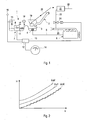
Fig. 2 zeigt für drei verschiedene Verformungen des Kraftstofftanks Füllstands-Füllvolumen-Kennlinien, die eine Beziehung zwischen dem Füllvolumen und einem gemessenen Füllstand im Kraftstofftank anzeigen; -
Fig. 3 zeigt ein schematisches Ablaufdiagramm von Schritten einer ersten erfindungsgemäßen Verfahrensalternative, bei der ein möglicherweise fehlerhaftes Signal ausgeblendet oder unterdrückt und durch ein anderes Signal ersetzt wird; -
Fig. 4 zeigt ein schematisches Ablaufdiagramm von Schritten einer zweiten erfindungsgemäßen Verfahrensalternative, bei der ein möglicherweise fehlerhaftes Signal korrigiert wird; -
Fig. 5 zeigt eine schematische Darstellung von Komponenten einer Steuerung zur Durchführung der ersten und zweiten Verfahrensalternative. - Der in
Fig. 1 schematisch dargestellte Kraftstofftank 1 eines Kraftfahrzeugs besitzt zum Betanken einen verschließbaren Einfüllstutzen 2, der am unteren Ende mit einer Klappe 3 versehen ist. Die Entnahme des Kraftstoffs aus dem Tank 1 erfolgt mittels einer Kraftstoffpumpe 4, die den Kraftstoff durch eine Kraftstoffleitung 5 zu einem Verbrennungsmotor 6 des Kraftfahrzeugs fördert. - Innerhalb des Kraftstofftanks 1 befindet sich eine Mess- und Signalerzeugungseinrichtung 7, die den aktuellen Füllstand des Kraftstoffs im Kraftstofftank 1 misst und ein mit diesem Füllstand korrelierendes Füllstandsignal erzeugt.
- Die Mess- und Signalerzeugungseinrichtung 7 umfasst dazu einen Füllstand-Signalgeber 8 und einen Schwimmkörper 9, der an der Kraftstoffoberfläche 10 schwimmt und über einen Arm 11 mit dem Signalgeber 8 gekoppelt ist. Wenn sich der Füllstand im Kraftstofftank 1 verändert, ändert sich die Winkelausrichtung des Arms 11 in Bezug zum Signalgeber 8. Durch diese Veränderung verändert sich innerhalb des Signalgebers 8 ein elektrischer Widerstand, der mit dem Füllstand des Kraftstoffs im Kraftstofftank 1 korreliert.
- Das vom Füllstand-Signalgeber 8 erzeugte Füllstandsignal wird einer Steuerung 12 zugeführt, die in ein Motorsteuergerät 13 des Verbrennungsmotors 6 integriert sein kann, und wird in der Steuerung 12 anhand von Kennlinien in ein entsprechendes Füllvolumen umgerechnet. Die Steuerung 12 erzeugt ein Volumensignal, das mit dem berechneten Füllvolumen korreliert, und von der Steuerung 12 aus zu einer Tankanzeige 14 auf einer Instrumententafel des Kraftfahrzeugs zugeführt wird.
- Wie in der eingangs genannten
DE 10 2010 045 212 A1 beschrieben ist, kann durch eine Verformung des Kraftstofftanks 1 zum einen der gemessene Füllstand verfälscht werden. Zum anderen ist auch die Beziehung zwischen dem gemessenen Füllstand und dem daraus errechneten Füllvolumen des Kraftstofftanks 1 von einer eventuellen Verformung des Kraftstofftanks 1 abhängig. Die Verformung des Kraftstofftanks 1 wiederum ist von der Druckdifferenz Δp zwischen dem Atmosphärendruck pA und dem Dampfdruck pK im Kraftstofftank 1 abhängig. - Zur Verdeutlichung dieser Abhängigkeit zeigt
Fig. 2 drei Füllstands-Füllvolumen-Kennlinien, die für drei verschiedene Druckdifferenzen Δp0, Δp1 und Δp2 im Kraftstofftank 1 die Beziehung zwischen dem Füllvolumen V und der gemessenen Füllhöhe H zeigen, wobei p0 = 0 mbar, p1 = - 20 mbar und p2 = - 40 mbar. Wie inFig. 2 nur für die unterste Kurve angezeigt ist, besitzen die Kennlinien in der Realität keinen stetigen Verlauf, sondern verlaufen treppenförmig. - Zur Messung des Dampfdrucks pK im Kraftstofftank 1 bzw. des Atmosphärendrucks pA dienen zwei Drucksensoren 15, 16, von denen der Drucksensor 15 in einem Gas- oder Kopfraum 17 des Kraftstofftanks 1 und der Drucksensor 16 außerhalb des Kraftstofftanks 1 angeordnet ist. Die Messwerte der beiden Drucksensoren 15, 16 werden der Steuerung 12 zugeführt.
- Der Kraftstofftank 1 ist mit einer Tankentlüftungseinrichtung ausgestattet, die beim Betanken des Kraftfahrzeugs sowie bei einem Anstieg der Umgebungstemperatur eine Entlüftung des Kraftstofftanks 1 gestattet. Die Tankentlüftungseinrichtung umfasst ein oder mehrere im Gas- oder Kopfraum 17 angeordnete Entlüftungsventile 18 (nur eines dargestellt), die durch eine Flüssigkeitsfalle 19 und eine Tankentlüftungsleitung 20 mit einem Aktivkohlefilter 21 außerhalb des Kraftstofftanks 1 verbunden sind.
- Der Aktivkohlefilter 21 verhindert, dass bei der Entlüftung des Kraftstofftanks 1 flüchtige Kohlenwasserstoffe (HC) aus dem Gas- oder Kopfraum 17 in die Umgebung gelangen und enthält zu diesem Zweck eine Füllung aus Aktivkohle, welche die flüchtigen Kohlenwasserstoffe (HC) absorbiert. Der Aktivkohlefilter 21 weist einen mit der Umgebung kommunizierenden Ein- und Auslass 22 auf. Zur Regeneration des Aktivkohlefilters 21 ist dieser durch eine Spülleitung 23 mit einem Ansaugtrakt 25 des Verbrennungsmotors 6 verbunden. Die Spülleitung 23 enthält ein elektromagnetisches Spülventil 24, das normalerweise geschlossen ist und von der Steuerung 12 zu Beginn jeder Regeneration des Aktivkohlefilters 21 geöffnet wird. Bei geöffnetem Spülventil 24 wird durch den Unterdruck im Ansaugtrakt 25 Umgebungsluft in den Aktivkohlefilter 21 und durch diesen hindurch in den Ansaugtrakt 25 angesaugt. Dabei wird der Aktivkohlefilter 21 gespült und die flüchtigen Kohlenwasserstoffe in den Brennräumen des Verbrennungsmotors 6 verbrannt. Nach Abschluss der Regeneration wird das Spülventil 24 wieder geschlossen.
- Wenn bei geöffnetem Spülventil 24 der im Ansaugtrakt 25 herrschende Unterdruck am Aktivkohlefilter 21 anliegt, pflanzt sich dieser Unterdruck durch die Tankentlüftungsleitung 20 bis in den Gas- oder Kopfraum 17 des Kraftstofftanks 1 hinein fort. Obwohl der Kraftstofftank 1 eine gewisse Verformungsfestigkeit besitzt, kann dadurch eine Verformung des Kraftstofftanks 1 verursacht werden, wenn der Unterdruck pU im Kraftstofftank 1 einen vorbestimmten kritischen Unterdruck-Schwellenwert pUkrit unterschreitet, das heißt, wenn die Druckdifferenz Δp zwischen dem Atmosphärendruck pA und dem Dampfdruck pK im Kraftstofftank 1 einen vorgegebenen Schwellenwert übersteigt.
- Um zu vermeiden, dass eine solche Verformung zur Anzeige eines fehlerhaften Füllvolumens an der Tankanzeige 14 führt, wird in der Steuerung 12 entweder das vom Füllstand-Signalgeber 8 erzeugte Füllstandsignal oder das daraus von der Steuerung 13 berechnete Volumensignal modifiziert, wobei nachfolgend zwei alternative Verfahrensalternativen für die Modifikation des Signals beschrieben werden.
- Beide Verfahrensalternativen haben als Gemeinsamkeit, dass die Steuerung 12 das möglicherweise fehlerhafte Füllstand- oder Volumensignal immer dann modifiziert, wenn der Unterdruck pU im Kraftstofftank 1 während einer Regeneration des Aktivkohlefilters 21, das heißt bei geöffnetem Spülventil 24, den vorbestimmten kritischen Unterdruck-Schwellenwert pUkrit unterschreitet.
- Eine weitere Gemeinsamkeit beider Verfahrensalternativen besteht darin, dass die Steuerung 12 den Unterdruck pU im Kraftstofftank 1 aus der Druckdifferenz Δp zwischen dem vom Drucksensor 16 gemessenen Atmosphärendruck pA und dem vom Drucksensor 15 gemessenen Druck pK im Kraftstofftank 1 ermittelt und die ermittelte Druckdifferenz Δp dann mit dem kritischen Unterdruck-Schwellenwert pUkrit vergleicht, um Unterschreitungen des Schwellenwerts festzustellen. Die Steuerung 12 enthält zu diesem Zweck drei Schaltungen 26, 27 und 28 sowie einen Speicher 29, wie in
Fig. 5 schematisch dargestellt. - Bei der Verfahrensalternative gemäß
Fig. 3 wird das möglicherweise fehlerhafte Volumensignal von der Schaltung 27 in der Steuerung 12 ausgeblendet oder unterdrückt und durch ein anderes Volumensignal ersetzt, das im Rahmen dieser Patentanmeldung auch als Ersatz-Signal bezeichnet wird. - Wie in
Fig. 3 dargestellt, wird dazu in einem Schritt S1 von der Schaltung 28 geprüft, ob das Spülventil 24 geöffnet ist. Sobald dies der Fall ist, wird in einem Schritt S2 von der Schaltung 26 geprüft, ob Δp < pUkrit oder ob Δp > pUkrit. - Wenn Δp < pUkrit, berechnet die Schaltung 27 in einem Schritt S3 aus dem mittels des Füllstand-Signalgebers 8 ermittelten Füllstand das Füllvolumen und führt in einem Schritt S4 ein dem Füllvolumen entsprechendes Füllvolumensignal ohne eine vorherige Modifikation zur Tankanzeige 14 zu. Darüber hinaus wird das Füllvolumen in einem Schritt S5 in dem mit der Schaltung 27 verbundenen Speicher 29 zwischengespeichert, wobei das aktuelle Füllvolumen jeweils das zuvor im Speicher 29 zwischengespeicherte Füllvolumen ersetzt.
- Wenn Δp > pKrit, dann unterdrückt die Schaltung 27 in einem Schritt S6 das möglicherweise fehlerhafte Volumensignal und führt der Tankanzeige 14 in einem Schritt S7 ein Volumensignal zu, das dem im Speicher 29 zwischengespeicherten Füllvolumen entspricht.
- Bei der Verfahrensalternative gemäß
Fig. 4 wird das möglicherweise fehlerhafte Füllvolumen hingegen von der Steuerung 12 korrigiert und ein korrigiertes Volumensignal zur Tankanzeige 14 zugeführt. - Wie in
Fig. 4 dargestellt, wird dabei ebenfalls in einem Schritt S1 von der Schaltung 28 geprüft, ob das Spülventil 24 geöffnet ist. Sobald dies der Fall ist, wird in einem Schritt S2 von der Schaltung 26 geprüft, ob Δp < pUkrit oder ob Δp > pUkrit. - Wenn Δp < pUkrit, berechnet die Schaltung 27 in einem Schritt S3 aus dem mittels des Füllstand-Signalgebers 8 ermittelten Füllstand das Füllvolumen und führt in einem Schritt S4 ein dem Füllvolumen entsprechendes Füllvolumensignal ohne eine vorherige Modifikation oder Korrektur zur Tankanzeige 14 zu.
- Wenn Δp > pKrit, ermittelt die Schaltung 27 in einem Schritt S5 einen vom jeweiligen Unterdruck pU im Kraftstofftank 1 abhängigen Korrekturwert, der die durch die Verformung des, Kraftstofftanks 1 bedingte Abweichung des Füllvolumens kompensiert. Die werkseitig berechneten Korrekturwerte sind zum Beispiel im Speicher 29 abgelegt. Die Schaltung 27 korrigiert dann in einem Schritt S6 das berechnete Füllvolumen um den ermittelten Korrekturwert und führt dann der Tankanzeige 14 in einem Schritt S7 ein Volumensignal zu, das dem korrigierten Füllvolumen entspricht.
- Bei beiden Verfahrensalternativen endet die Zufuhr eines modifizierten Füllvolumensignals zur Tankanzeige 14, sobald entweder von der Schaltung 26 festgestellt wird, dass der im Kraftstofftank 1 herrschende Unterdruck pU den kritischen Unterdruck-Schwellenwert pUkrit nicht mehr unterschreitet oder sobald von der Schaltung 28 das Schließen des Spülventils 24 festgestellt wird.
-
- 1
- Kraftstofftank
- 2
- Einfüllstutzen
- 3
- Klappe
- 4
- Kraftstoffpumpe
- 5
- Kraftstoffleitung
- 6
- Verbrennungsmotor
- 7
- Mess- und Signalerzeugungseinrichtung
- 8
- Füllstand-Signalgeber
- 9
- Schwimmkörper
- 10
- Kraftstoffoberfläche
- 11
- Arm
- 12
- Steuerung
- 13
- Motorsteuergerät
- 14
- Tankanzeige
- 15
- Drucksensor
- 16
- Drucksensor
- 17
- Gas- oder Kopfraum
- 18
- Entlüftungsventil
- 19
- Flüssigkeitsfalle
- 20
- Tankentlüftungsleitung
- 21
- Aktivkohlefilter
- 22
- Ein- und Auslass
- 23
- Spülleitung
- 24
- Spülventil
- 25
- Ansaugtrakt
- 26
- Schaltung
- 27
- Schaltung
- 28
- Schaltung
- 29
- Speicher
Claims (10)
- Kraftstofftank (1) für einen Verbrennungsmotor (6), mit Einrichtungen (7, 12) zum Ermitteln des Füllstands oder Füllvolumens im Kraftstofftank (1), zum Erzeugen eines mit dem Füllstand oder Füllvolumen korrelierenden Signals und zum Zuführen des Signals zu einer Tankanzeige (14), sowie mit einer Einrichtung (27) zum Modifizieren des Signals bei einer Verformung des Kraftstofftanks (1), gekennzeichnet durch Mittel (28) zum Aktivieren der Einrichtung (27) in Abhängigkeit vom Öffnungszustand eines Ventils (24) zwischen einem mit dem Kraftstofftank (1) kommunizierenden Aktivkohlefilter (21) und einem Ansaugtrakt (25) des Verbrennungsmotors (6).
- Kraftstofftank (1) nach Anspruch 1, dadurch gekennzeichnet, dass die Einrichtung (27) das Signal unterdrückt oder korrigiert, wenn bei geöffnetem Ventil (24) ein im Kraftstofftank (1) herrschender Unterdruck pU einen kritischen Unterdruck-Schwellenwert pUkrit unterschreitet.
- Kraftstofftank (1) nach Anspruch 1 oder 2, dadurch gekennzeichnet, dass die Einrichtungen (7, 12) das Signal wieder zur Tankanzeige (14) zuführen, sobald der im Kraftstofftank (1) herrschende Unterdruck pU den kritischen Unterdruck-Schwellenwert pUkrit nicht mehr unterschreitet.
- Kraftstofftank (1) nach einem der vorangehenden Ansprüche, gekennzeichnet durch zwei Drucksensoren (15, 16) zur Messung des Atmosphärendrucks pA und des Dampfdrucks pK im Kraftstofftank (1) als Grundlage für die Ermittlung des im Kraftstofftank (1) herrschenden Unterdrucks pU.
- Kraftstofftank (1) nach einem der vorangehenden Ansprüche, dadurch gekennzeichnet, dass die Einrichtung (27) das Signal unterdrückt und während der Unterdrückung des Signals ein Ersatz-Signal zur Tankanzeige (14) zuführt, das mit einem unmittelbar vor dem Öffnen des Ventils (24) ermittelten und gespeicherten Füllstand oder Füllvolumen korreliert.
- Kraftstofftank (1) nach einem der Ansprüche 1 bis 4, dadurch gekennzeichnet, dass die Einrichtung (27) das Signal korrigiert und ein korrigiertes, die Verformung des Kraftstofftanks (1) berücksichtigendes Signal zur Tankanzeige (14) zuführt.
- Verfahren zum Anzeigen eines Füllstands oder Füllvolumens eines Kraftstofftanks (1) eines Verbrennungsmotors (6), bei dem der Füllstand oder das Füllvolumen ermittelt, ein mit dem Füllstand oder Füllvolumen korrelierendes Signal erzeugt und zu einer Tankanzeige (14) zugeführt wird, und bei dem das Signal bei einer Verformung des Kraftstofftanks (1) modifiziert wird, dadurch gekennzeichnet, dass die Modifikation des Signals bei der Regeneration eines mit dem Kraftstofftank (1) kommunizierenden Aktivkohlefilters (21) ausgelöst wird.
- Verfahren nach Anspruch 7, dadurch gekennzeichnet, dass das Signal bei der Regeneration des Aktivkohlefilters (21) modifiziert wird, wenn ein im Kraftstofftank (1) herrschender Unterdruck pU einen kritischen Unterdruck-Schwellenwert pUkrit unterschreitet.
- Verfahren nach Anspruch 7 oder 8, dadurch gekennzeichnet, dass das Signal unterdrückt oder ausgeblendet wird und der Tankanzeige (14) statt dessen ein Ersatz-Signal zugeführt wird, das mit einem unmittelbar zuvor ermittelten und gespeicherten Füllstand oder Füllvolumen korreliert.
- Verfahren nach Anspruch 7 oder 8, dadurch gekennzeichnet, dass das modifizierte Signal ein korrigiertes, die Verformung des Kraftstofftanks (1) berücksichtigendes Signal ist.
Applications Claiming Priority (1)
| Application Number | Priority Date | Filing Date | Title |
|---|---|---|---|
| DE102014009634.3A DE102014009634A1 (de) | 2014-06-27 | 2014-06-27 | Kraftstofftank mit einem Aktivkohlefilter und Verfahren zum Anzeigen des Kraftstofffüllstands im Kraftstofftank mit Signalunterdrückung bei einem kritischen Unterdruck während der Regeneration des Aktivkohlefilters |
Publications (2)
| Publication Number | Publication Date |
|---|---|
| EP2960092A1 true EP2960092A1 (de) | 2015-12-30 |
| EP2960092B1 EP2960092B1 (de) | 2017-12-27 |
Family
ID=53054844
Family Applications (1)
| Application Number | Title | Priority Date | Filing Date |
|---|---|---|---|
| EP15001382.9A Active EP2960092B1 (de) | 2014-06-27 | 2015-05-07 | Kraftstofftank mit einem aktivkohlefilter und verfahren zum anzeigen des kraftstofffüllstands im kraftstofftank mit signalunterdrückung bei einem kritischen unterdruck während der regeneration des aktivkohlefilters |
Country Status (4)
| Country | Link |
|---|---|
| US (1) | US20150377686A1 (de) |
| EP (1) | EP2960092B1 (de) |
| CN (1) | CN105201693B (de) |
| DE (1) | DE102014009634A1 (de) |
Families Citing this family (4)
| Publication number | Priority date | Publication date | Assignee | Title |
|---|---|---|---|---|
| US20170114758A1 (en) * | 2015-09-29 | 2017-04-27 | Eagle Actuator Components Gmbh & Co. Kg | Positioning an activated carbon filter in an arrangement for its regeneration |
| US10234353B2 (en) * | 2016-04-21 | 2019-03-19 | Honeywell International Inc. | Automatic pressure correction for level gauges in storage tanks |
| US10268199B2 (en) * | 2016-08-16 | 2019-04-23 | Ford Global Technologies, Llc | Managing vehicle refueling operations |
| CN113029278A (zh) * | 2021-03-05 | 2021-06-25 | 徐州徐工施维英机械有限公司 | 料仓料位测量装置及方法、料仓、混凝土搅拌站 |
Citations (7)
| Publication number | Priority date | Publication date | Assignee | Title |
|---|---|---|---|---|
| DE4003751A1 (de) * | 1990-02-08 | 1991-08-14 | Bosch Gmbh Robert | Tankentlueftungsanlage fuer ein kraftfahrzeug und verfahren zum ueberpruefen deren funktionstuechtigkeit |
| DE4203099A1 (de) * | 1992-02-04 | 1993-08-05 | Bosch Gmbh Robert | Verfahren und vorrichtung zur tankfuellstandserkennung |
| US20070113633A1 (en) | 2005-11-22 | 2007-05-24 | Nissan Motor Co., Ltd. | Leak check apparatus for fuel vapor processing apparatus |
| US20090277251A1 (en) | 2008-05-09 | 2009-11-12 | Nissan Motor Co., Ltd. | Leak diagnostic apparatus for an evaporative emission control system |
| DE102009030077A1 (de) * | 2008-06-24 | 2009-12-31 | Inergy Automotive Systems Research (S.A.) | Verfahren zum Simulieren der Vermessung eines Flüssigkeitstanks |
| JP2012036769A (ja) * | 2010-08-04 | 2012-02-23 | Toyota Motor Corp | 燃料供給系リーク検出方法及び燃料供給系リーク診断装置 |
| DE102010045212A1 (de) | 2010-09-13 | 2012-03-15 | Audi Ag | Messeinrichtung und Verfahren zum Ermitteln eines Flüssigkeitsfüllstands in einem Kraftstofftank |
Family Cites Families (4)
| Publication number | Priority date | Publication date | Assignee | Title |
|---|---|---|---|---|
| JP3671685B2 (ja) * | 1998-08-19 | 2005-07-13 | トヨタ自動車株式会社 | 燃料量検出装置 |
| DE10111923A1 (de) * | 2001-03-13 | 2002-10-02 | Bosch Gmbh Robert | Verfahren für eine Tank-Füllstandbestimmung bei Kraftfahrzeugen |
| US8327695B2 (en) * | 2010-02-11 | 2012-12-11 | GM Global Technology Operations LLC | Restricted filter diagnostic system and method |
| EP2589507A1 (de) * | 2011-11-07 | 2013-05-08 | Inergy Automotive Systems Research (Société Anonyme) | Eichmethode für einen Kraftstoffbehälter aus Plastik eines Hybridfahrzeugs |
-
2014
- 2014-06-27 DE DE102014009634.3A patent/DE102014009634A1/de not_active Withdrawn
-
2015
- 2015-05-07 EP EP15001382.9A patent/EP2960092B1/de active Active
- 2015-06-26 CN CN201510363903.0A patent/CN105201693B/zh active Active
- 2015-06-26 US US14/751,434 patent/US20150377686A1/en not_active Abandoned
Patent Citations (8)
| Publication number | Priority date | Publication date | Assignee | Title |
|---|---|---|---|---|
| DE4003751A1 (de) * | 1990-02-08 | 1991-08-14 | Bosch Gmbh Robert | Tankentlueftungsanlage fuer ein kraftfahrzeug und verfahren zum ueberpruefen deren funktionstuechtigkeit |
| DE4203099A1 (de) * | 1992-02-04 | 1993-08-05 | Bosch Gmbh Robert | Verfahren und vorrichtung zur tankfuellstandserkennung |
| US20070113633A1 (en) | 2005-11-22 | 2007-05-24 | Nissan Motor Co., Ltd. | Leak check apparatus for fuel vapor processing apparatus |
| US20090277251A1 (en) | 2008-05-09 | 2009-11-12 | Nissan Motor Co., Ltd. | Leak diagnostic apparatus for an evaporative emission control system |
| DE102009030077A1 (de) * | 2008-06-24 | 2009-12-31 | Inergy Automotive Systems Research (S.A.) | Verfahren zum Simulieren der Vermessung eines Flüssigkeitstanks |
| JP2012036769A (ja) * | 2010-08-04 | 2012-02-23 | Toyota Motor Corp | 燃料供給系リーク検出方法及び燃料供給系リーク診断装置 |
| DE102010045212A1 (de) | 2010-09-13 | 2012-03-15 | Audi Ag | Messeinrichtung und Verfahren zum Ermitteln eines Flüssigkeitsfüllstands in einem Kraftstofftank |
| EP2437036A1 (de) * | 2010-09-13 | 2012-04-04 | Audi AG | Messeinrichtung und Verfahren zum Ermitteln eines Flüssigkeitsfüllstands in einem Kraftstofftank |
Also Published As
| Publication number | Publication date |
|---|---|
| DE102014009634A1 (de) | 2015-12-31 |
| US20150377686A1 (en) | 2015-12-31 |
| CN105201693A (zh) | 2015-12-30 |
| CN105201693B (zh) | 2017-09-01 |
| EP2960092B1 (de) | 2017-12-27 |
Similar Documents
| Publication | Publication Date | Title |
|---|---|---|
| EP2960092B1 (de) | Kraftstofftank mit einem aktivkohlefilter und verfahren zum anzeigen des kraftstofffüllstands im kraftstofftank mit signalunterdrückung bei einem kritischen unterdruck während der regeneration des aktivkohlefilters | |
| DE112012005026B4 (de) | Verfahren zum Ermitteln einer Leckage in einem Dampfmanagementsystem eines Kraftstoffsystems eines Kraftfahrzeugs sowie Dampfmanagementsysteme für ein Kraftfahrzeug mit Mitteln zum Ermitteln von Leckagen | |
| DE102010031216A1 (de) | Verfahren zur Prüfung der Funktionsfähigkeit eines Tankabsperrventils einer Kraftstoff-Tankanlage | |
| DE102012219048A1 (de) | Verfahren zur Überwachung der Dichtigkeit eines Kraftstofftanksystems | |
| DE102015004657A1 (de) | Verarbeitungsvorrichtung für verdampften Kraftstoff | |
| DE112018003088T5 (de) | Leckerfasser für kraftstoffdampfbehandlungsvorrichtung | |
| EP1760303B1 (de) | Verfahren zur Überprüfung der Gasdichtheit einer Kraftfahrzeug- Tankentlüftungsanlage | |
| DE102006034076A1 (de) | Verfahren zur Tankleckdiagnose in einer Tankentlüftungsvorrichtung | |
| DE102015006144A1 (de) | Kraftstoffdampfverarbeitungsvorrichtung | |
| DE102006056384A1 (de) | Verfahren zur Funktionsüberprüfung eines Druckschalters einer Tankentlüftungsanlage, Steuereinrichtung und Brennkraftmaschine | |
| EP0952332B1 (de) | Verfahren zur Bestimmung von Leckagen im Kraftstoffversorgungssystem eines Kraftfahrzeuges | |
| DE102005022121B3 (de) | Verfahren zur Ermittlung der Einspritzkorrektur während der Überprüfung der Dichtheit einer Tankentlüftungsanlage | |
| DE102009057227B4 (de) | Verfahren zum Betreiben eines Kraftstoffsystems | |
| EP3390130B1 (de) | System zur füllstandsbestimmung | |
| DE102015221536A1 (de) | Vorrichtung und Verfahren zur Tankleckagediagnose | |
| EP3368362B1 (de) | Verfahren zum überprüfen der dichtheit einer kraftstoffversorgungsanlage | |
| DE102020205241B4 (de) | Vorrichtung zur Diagnose einer Verdunstungssystemleckage und eines Tankentlüftungsleitungstraktes eines verbrennungsmotorisch betriebenen Kraftfahrzeugs | |
| DE19830234C2 (de) | Verfahren zum Prüfen einer Tankanlage in einem Kraftfahrzeug auf Dichtheit | |
| DE10126521B4 (de) | Verfahren und Vorrichtung zur Tankleckdiagnose bei erhöhter Brennstoffausgasung | |
| DE102018204717B3 (de) | Verfahren und Vorrichtung zur Tankleckdiagnose bei einem Kraftfahrzeug | |
| DE102016221901A1 (de) | Verfahren zur Steuerung einer Tankentlüftung für einen Kraftstofftank | |
| DE102015214322A1 (de) | Verfahren zum Ermitteln der Beladung eines Speichers für Kohlenwasserstoffe | |
| DE102010048844A1 (de) | Kraftstofftank mit einem Tankeinlassventil | |
| EP1924768B1 (de) | Verfahren zum betrieb einer einen tank aufweisenden tankanlage und tankanlage | |
| DE102012218933A1 (de) | Verfahren zur Bestimmung der Beladung eines Aktivkohlefilters in einem Kraftstofftankentlüftungssystem |
Legal Events
| Date | Code | Title | Description |
|---|---|---|---|
| PUAI | Public reference made under article 153(3) epc to a published international application that has entered the european phase |
Free format text: ORIGINAL CODE: 0009012 |
|
| AK | Designated contracting states |
Kind code of ref document: A1 Designated state(s): AL AT BE BG CH CY CZ DE DK EE ES FI FR GB GR HR HU IE IS IT LI LT LU LV MC MK MT NL NO PL PT RO RS SE SI SK SM TR |
|
| AX | Request for extension of the european patent |
Extension state: BA ME |
|
| 17P | Request for examination filed |
Effective date: 20160630 |
|
| RBV | Designated contracting states (corrected) |
Designated state(s): AL AT BE BG CH CY CZ DE DK EE ES FI FR GB GR HR HU IE IS IT LI LT LU LV MC MK MT NL NO PL PT RO RS SE SI SK SM TR |
|
| REG | Reference to a national code |
Ref country code: DE Ref legal event code: R079 Ref document number: 502015002658 Country of ref document: DE Free format text: PREVIOUS MAIN CLASS: B60K0015030000 Ipc: F02M0025080000 |
|
| GRAP | Despatch of communication of intention to grant a patent |
Free format text: ORIGINAL CODE: EPIDOSNIGR1 |
|
| RIC1 | Information provided on ipc code assigned before grant |
Ipc: G01F 23/32 20060101ALI20170914BHEP Ipc: B60K 15/03 20060101ALI20170914BHEP Ipc: G01F 23/00 20060101ALI20170914BHEP Ipc: B60K 15/035 20060101ALI20170914BHEP Ipc: F02M 25/08 20060101AFI20170914BHEP |
|
| INTG | Intention to grant announced |
Effective date: 20171009 |
|
| GRAS | Grant fee paid |
Free format text: ORIGINAL CODE: EPIDOSNIGR3 |
|
| GRAA | (expected) grant |
Free format text: ORIGINAL CODE: 0009210 |
|
| AK | Designated contracting states |
Kind code of ref document: B1 Designated state(s): AL AT BE BG CH CY CZ DE DK EE ES FI FR GB GR HR HU IE IS IT LI LT LU LV MC MK MT NL NO PL PT RO RS SE SI SK SM TR |
|
| REG | Reference to a national code |
Ref country code: GB Ref legal event code: FG4D Free format text: NOT ENGLISH |
|
| REG | Reference to a national code |
Ref country code: CH Ref legal event code: EP |
|
| REG | Reference to a national code |
Ref country code: AT Ref legal event code: REF Ref document number: 958529 Country of ref document: AT Kind code of ref document: T Effective date: 20180115 |
|
| REG | Reference to a national code |
Ref country code: IE Ref legal event code: FG4D Free format text: LANGUAGE OF EP DOCUMENT: GERMAN |
|
| REG | Reference to a national code |
Ref country code: DE Ref legal event code: R096 Ref document number: 502015002658 Country of ref document: DE |
|
| PG25 | Lapsed in a contracting state [announced via postgrant information from national office to epo] |
Ref country code: FI Free format text: LAPSE BECAUSE OF FAILURE TO SUBMIT A TRANSLATION OF THE DESCRIPTION OR TO PAY THE FEE WITHIN THE PRESCRIBED TIME-LIMIT Effective date: 20171227 Ref country code: LT Free format text: LAPSE BECAUSE OF FAILURE TO SUBMIT A TRANSLATION OF THE DESCRIPTION OR TO PAY THE FEE WITHIN THE PRESCRIBED TIME-LIMIT Effective date: 20171227 Ref country code: NO Free format text: LAPSE BECAUSE OF FAILURE TO SUBMIT A TRANSLATION OF THE DESCRIPTION OR TO PAY THE FEE WITHIN THE PRESCRIBED TIME-LIMIT Effective date: 20180327 |
|
| REG | Reference to a national code |
Ref country code: NL Ref legal event code: MP Effective date: 20171227 |
|
| REG | Reference to a national code |
Ref country code: LT Ref legal event code: MG4D |
|
| REG | Reference to a national code |
Ref country code: FR Ref legal event code: PLFP Year of fee payment: 4 |
|
| PG25 | Lapsed in a contracting state [announced via postgrant information from national office to epo] |
Ref country code: BG Free format text: LAPSE BECAUSE OF FAILURE TO SUBMIT A TRANSLATION OF THE DESCRIPTION OR TO PAY THE FEE WITHIN THE PRESCRIBED TIME-LIMIT Effective date: 20180327 Ref country code: GR Free format text: LAPSE BECAUSE OF FAILURE TO SUBMIT A TRANSLATION OF THE DESCRIPTION OR TO PAY THE FEE WITHIN THE PRESCRIBED TIME-LIMIT Effective date: 20180328 Ref country code: RS Free format text: LAPSE BECAUSE OF FAILURE TO SUBMIT A TRANSLATION OF THE DESCRIPTION OR TO PAY THE FEE WITHIN THE PRESCRIBED TIME-LIMIT Effective date: 20171227 Ref country code: LV Free format text: LAPSE BECAUSE OF FAILURE TO SUBMIT A TRANSLATION OF THE DESCRIPTION OR TO PAY THE FEE WITHIN THE PRESCRIBED TIME-LIMIT Effective date: 20171227 Ref country code: HR Free format text: LAPSE BECAUSE OF FAILURE TO SUBMIT A TRANSLATION OF THE DESCRIPTION OR TO PAY THE FEE WITHIN THE PRESCRIBED TIME-LIMIT Effective date: 20171227 |
|
| PG25 | Lapsed in a contracting state [announced via postgrant information from national office to epo] |
Ref country code: NL Free format text: LAPSE BECAUSE OF FAILURE TO SUBMIT A TRANSLATION OF THE DESCRIPTION OR TO PAY THE FEE WITHIN THE PRESCRIBED TIME-LIMIT Effective date: 20171227 |
|
| PG25 | Lapsed in a contracting state [announced via postgrant information from national office to epo] |
Ref country code: CZ Free format text: LAPSE BECAUSE OF FAILURE TO SUBMIT A TRANSLATION OF THE DESCRIPTION OR TO PAY THE FEE WITHIN THE PRESCRIBED TIME-LIMIT Effective date: 20171227 Ref country code: ES Free format text: LAPSE BECAUSE OF FAILURE TO SUBMIT A TRANSLATION OF THE DESCRIPTION OR TO PAY THE FEE WITHIN THE PRESCRIBED TIME-LIMIT Effective date: 20171227 Ref country code: EE Free format text: LAPSE BECAUSE OF FAILURE TO SUBMIT A TRANSLATION OF THE DESCRIPTION OR TO PAY THE FEE WITHIN THE PRESCRIBED TIME-LIMIT Effective date: 20171227 Ref country code: CY Free format text: LAPSE BECAUSE OF FAILURE TO SUBMIT A TRANSLATION OF THE DESCRIPTION OR TO PAY THE FEE WITHIN THE PRESCRIBED TIME-LIMIT Effective date: 20171227 Ref country code: SK Free format text: LAPSE BECAUSE OF FAILURE TO SUBMIT A TRANSLATION OF THE DESCRIPTION OR TO PAY THE FEE WITHIN THE PRESCRIBED TIME-LIMIT Effective date: 20171227 |
|
| PG25 | Lapsed in a contracting state [announced via postgrant information from national office to epo] |
Ref country code: IT Free format text: LAPSE BECAUSE OF FAILURE TO SUBMIT A TRANSLATION OF THE DESCRIPTION OR TO PAY THE FEE WITHIN THE PRESCRIBED TIME-LIMIT Effective date: 20171227 Ref country code: IS Free format text: LAPSE BECAUSE OF FAILURE TO SUBMIT A TRANSLATION OF THE DESCRIPTION OR TO PAY THE FEE WITHIN THE PRESCRIBED TIME-LIMIT Effective date: 20180427 Ref country code: SM Free format text: LAPSE BECAUSE OF FAILURE TO SUBMIT A TRANSLATION OF THE DESCRIPTION OR TO PAY THE FEE WITHIN THE PRESCRIBED TIME-LIMIT Effective date: 20171227 Ref country code: RO Free format text: LAPSE BECAUSE OF FAILURE TO SUBMIT A TRANSLATION OF THE DESCRIPTION OR TO PAY THE FEE WITHIN THE PRESCRIBED TIME-LIMIT Effective date: 20171227 Ref country code: PL Free format text: LAPSE BECAUSE OF FAILURE TO SUBMIT A TRANSLATION OF THE DESCRIPTION OR TO PAY THE FEE WITHIN THE PRESCRIBED TIME-LIMIT Effective date: 20171227 |
|
| PG25 | Lapsed in a contracting state [announced via postgrant information from national office to epo] |
Ref country code: MT Free format text: LAPSE BECAUSE OF FAILURE TO SUBMIT A TRANSLATION OF THE DESCRIPTION OR TO PAY THE FEE WITHIN THE PRESCRIBED TIME-LIMIT Effective date: 20171227 |
|
| REG | Reference to a national code |
Ref country code: DE Ref legal event code: R097 Ref document number: 502015002658 Country of ref document: DE |
|
| PLBE | No opposition filed within time limit |
Free format text: ORIGINAL CODE: 0009261 |
|
| STAA | Information on the status of an ep patent application or granted ep patent |
Free format text: STATUS: NO OPPOSITION FILED WITHIN TIME LIMIT |
|
| PG25 | Lapsed in a contracting state [announced via postgrant information from national office to epo] |
Ref country code: DK Free format text: LAPSE BECAUSE OF FAILURE TO SUBMIT A TRANSLATION OF THE DESCRIPTION OR TO PAY THE FEE WITHIN THE PRESCRIBED TIME-LIMIT Effective date: 20171227 |
|
| 26N | No opposition filed |
Effective date: 20180928 |
|
| REG | Reference to a national code |
Ref country code: CH Ref legal event code: PL |
|
| REG | Reference to a national code |
Ref country code: BE Ref legal event code: MM Effective date: 20180531 |
|
| PG25 | Lapsed in a contracting state [announced via postgrant information from national office to epo] |
Ref country code: MC Free format text: LAPSE BECAUSE OF FAILURE TO SUBMIT A TRANSLATION OF THE DESCRIPTION OR TO PAY THE FEE WITHIN THE PRESCRIBED TIME-LIMIT Effective date: 20171227 |
|
| REG | Reference to a national code |
Ref country code: IE Ref legal event code: MM4A |
|
| PG25 | Lapsed in a contracting state [announced via postgrant information from national office to epo] |
Ref country code: CH Free format text: LAPSE BECAUSE OF NON-PAYMENT OF DUE FEES Effective date: 20180531 Ref country code: SI Free format text: LAPSE BECAUSE OF FAILURE TO SUBMIT A TRANSLATION OF THE DESCRIPTION OR TO PAY THE FEE WITHIN THE PRESCRIBED TIME-LIMIT Effective date: 20171227 Ref country code: LI Free format text: LAPSE BECAUSE OF NON-PAYMENT OF DUE FEES Effective date: 20180531 |
|
| PG25 | Lapsed in a contracting state [announced via postgrant information from national office to epo] |
Ref country code: LU Free format text: LAPSE BECAUSE OF NON-PAYMENT OF DUE FEES Effective date: 20180507 |
|
| PG25 | Lapsed in a contracting state [announced via postgrant information from national office to epo] |
Ref country code: IE Free format text: LAPSE BECAUSE OF NON-PAYMENT OF DUE FEES Effective date: 20180507 |
|
| PG25 | Lapsed in a contracting state [announced via postgrant information from national office to epo] |
Ref country code: BE Free format text: LAPSE BECAUSE OF NON-PAYMENT OF DUE FEES Effective date: 20180531 |
|
| PG25 | Lapsed in a contracting state [announced via postgrant information from national office to epo] |
Ref country code: TR Free format text: LAPSE BECAUSE OF FAILURE TO SUBMIT A TRANSLATION OF THE DESCRIPTION OR TO PAY THE FEE WITHIN THE PRESCRIBED TIME-LIMIT Effective date: 20171227 |
|
| PG25 | Lapsed in a contracting state [announced via postgrant information from national office to epo] |
Ref country code: PT Free format text: LAPSE BECAUSE OF FAILURE TO SUBMIT A TRANSLATION OF THE DESCRIPTION OR TO PAY THE FEE WITHIN THE PRESCRIBED TIME-LIMIT Effective date: 20171227 |
|
| PG25 | Lapsed in a contracting state [announced via postgrant information from national office to epo] |
Ref country code: SE Free format text: LAPSE BECAUSE OF FAILURE TO SUBMIT A TRANSLATION OF THE DESCRIPTION OR TO PAY THE FEE WITHIN THE PRESCRIBED TIME-LIMIT Effective date: 20171227 Ref country code: HU Free format text: LAPSE BECAUSE OF FAILURE TO SUBMIT A TRANSLATION OF THE DESCRIPTION OR TO PAY THE FEE WITHIN THE PRESCRIBED TIME-LIMIT; INVALID AB INITIO Effective date: 20150507 Ref country code: MK Free format text: LAPSE BECAUSE OF NON-PAYMENT OF DUE FEES Effective date: 20171227 |
|
| PG25 | Lapsed in a contracting state [announced via postgrant information from national office to epo] |
Ref country code: AL Free format text: LAPSE BECAUSE OF FAILURE TO SUBMIT A TRANSLATION OF THE DESCRIPTION OR TO PAY THE FEE WITHIN THE PRESCRIBED TIME-LIMIT Effective date: 20171227 |
|
| REG | Reference to a national code |
Ref country code: AT Ref legal event code: MM01 Ref document number: 958529 Country of ref document: AT Kind code of ref document: T Effective date: 20200507 |
|
| PG25 | Lapsed in a contracting state [announced via postgrant information from national office to epo] |
Ref country code: AT Free format text: LAPSE BECAUSE OF NON-PAYMENT OF DUE FEES Effective date: 20200507 |
|
| P01 | Opt-out of the competence of the unified patent court (upc) registered |
Effective date: 20230530 |
|
| PGFP | Annual fee paid to national office [announced via postgrant information from national office to epo] |
Ref country code: FR Payment date: 20230523 Year of fee payment: 9 Ref country code: DE Payment date: 20230531 Year of fee payment: 9 |
|
| PGFP | Annual fee paid to national office [announced via postgrant information from national office to epo] |
Ref country code: GB Payment date: 20230526 Year of fee payment: 9 |