EP2958074A1 - Procédé et dispositif d'affichage avec optimisation de répartition de pixel - Google Patents
Procédé et dispositif d'affichage avec optimisation de répartition de pixel Download PDFInfo
- Publication number
- EP2958074A1 EP2958074A1 EP14305923.6A EP14305923A EP2958074A1 EP 2958074 A1 EP2958074 A1 EP 2958074A1 EP 14305923 A EP14305923 A EP 14305923A EP 2958074 A1 EP2958074 A1 EP 2958074A1
- Authority
- EP
- European Patent Office
- Prior art keywords
- display device
- content
- viewer
- area
- display
- Prior art date
- Legal status (The legal status is an assumption and is not a legal conclusion. Google has not performed a legal analysis and makes no representation as to the accuracy of the status listed.)
- Withdrawn
Links
- 238000000034 method Methods 0.000 title claims abstract description 18
- 238000005457 optimization Methods 0.000 title description 2
- 230000009466 transformation Effects 0.000 claims abstract description 21
- 230000003287 optical effect Effects 0.000 claims description 51
- 230000004044 response Effects 0.000 claims description 10
- 230000008859 change Effects 0.000 claims description 3
- 210000003128 head Anatomy 0.000 description 11
- 230000004304 visual acuity Effects 0.000 description 9
- 230000006870 function Effects 0.000 description 7
- 238000007654 immersion Methods 0.000 description 7
- 230000008569 process Effects 0.000 description 5
- 230000003247 decreasing effect Effects 0.000 description 4
- 230000008901 benefit Effects 0.000 description 3
- 230000007423 decrease Effects 0.000 description 3
- 238000013461 design Methods 0.000 description 3
- 238000005259 measurement Methods 0.000 description 3
- 230000005043 peripheral vision Effects 0.000 description 3
- 238000012545 processing Methods 0.000 description 3
- 210000001747 pupil Anatomy 0.000 description 3
- 230000004308 accommodation Effects 0.000 description 2
- 238000010586 diagram Methods 0.000 description 2
- 239000011521 glass Substances 0.000 description 2
- 230000004048 modification Effects 0.000 description 2
- 238000012986 modification Methods 0.000 description 2
- 230000002093 peripheral effect Effects 0.000 description 2
- 230000000007 visual effect Effects 0.000 description 2
- 241000226585 Antennaria plantaginifolia Species 0.000 description 1
- 230000005540 biological transmission Effects 0.000 description 1
- 239000003795 chemical substances by application Substances 0.000 description 1
- 230000006835 compression Effects 0.000 description 1
- 238000007906 compression Methods 0.000 description 1
- 238000001514 detection method Methods 0.000 description 1
- 210000005069 ears Anatomy 0.000 description 1
- 230000004424 eye movement Effects 0.000 description 1
- 210000000873 fovea centralis Anatomy 0.000 description 1
- 238000003384 imaging method Methods 0.000 description 1
- 239000004973 liquid crystal related substance Substances 0.000 description 1
- 230000033001 locomotion Effects 0.000 description 1
- 239000000463 material Substances 0.000 description 1
- 230000008520 organization Effects 0.000 description 1
- 238000005070 sampling Methods 0.000 description 1
- 238000000926 separation method Methods 0.000 description 1
- 230000003068 static effect Effects 0.000 description 1
- 238000012360 testing method Methods 0.000 description 1
- 238000012546 transfer Methods 0.000 description 1
Images


Classifications
-
- G—PHYSICS
- G06—COMPUTING; CALCULATING OR COUNTING
- G06T—IMAGE DATA PROCESSING OR GENERATION, IN GENERAL
- G06T3/00—Geometric image transformations in the plane of the image
- G06T3/40—Scaling of whole images or parts thereof, e.g. expanding or contracting
- G06T3/4023—Scaling of whole images or parts thereof, e.g. expanding or contracting based on decimating pixels or lines of pixels; based on inserting pixels or lines of pixels
-
- G—PHYSICS
- G02—OPTICS
- G02B—OPTICAL ELEMENTS, SYSTEMS OR APPARATUS
- G02B27/00—Optical systems or apparatus not provided for by any of the groups G02B1/00 - G02B26/00, G02B30/00
- G02B27/01—Head-up displays
-
- G—PHYSICS
- G02—OPTICS
- G02B—OPTICAL ELEMENTS, SYSTEMS OR APPARATUS
- G02B27/00—Optical systems or apparatus not provided for by any of the groups G02B1/00 - G02B26/00, G02B30/00
- G02B27/01—Head-up displays
- G02B27/017—Head mounted
-
- G—PHYSICS
- G02—OPTICS
- G02B—OPTICAL ELEMENTS, SYSTEMS OR APPARATUS
- G02B27/00—Optical systems or apparatus not provided for by any of the groups G02B1/00 - G02B26/00, G02B30/00
- G02B27/01—Head-up displays
- G02B27/017—Head mounted
- G02B27/0176—Head mounted characterised by mechanical features
-
- G—PHYSICS
- G02—OPTICS
- G02B—OPTICAL ELEMENTS, SYSTEMS OR APPARATUS
- G02B27/00—Optical systems or apparatus not provided for by any of the groups G02B1/00 - G02B26/00, G02B30/00
- G02B27/02—Viewing or reading apparatus
-
- G—PHYSICS
- G06—COMPUTING; CALCULATING OR COUNTING
- G06F—ELECTRIC DIGITAL DATA PROCESSING
- G06F18/00—Pattern recognition
-
- G—PHYSICS
- G06—COMPUTING; CALCULATING OR COUNTING
- G06F—ELECTRIC DIGITAL DATA PROCESSING
- G06F3/00—Input arrangements for transferring data to be processed into a form capable of being handled by the computer; Output arrangements for transferring data from processing unit to output unit, e.g. interface arrangements
- G06F3/01—Input arrangements or combined input and output arrangements for interaction between user and computer
- G06F3/011—Arrangements for interaction with the human body, e.g. for user immersion in virtual reality
- G06F3/012—Head tracking input arrangements
-
- G—PHYSICS
- G06—COMPUTING; CALCULATING OR COUNTING
- G06F—ELECTRIC DIGITAL DATA PROCESSING
- G06F3/00—Input arrangements for transferring data to be processed into a form capable of being handled by the computer; Output arrangements for transferring data from processing unit to output unit, e.g. interface arrangements
- G06F3/01—Input arrangements or combined input and output arrangements for interaction between user and computer
- G06F3/011—Arrangements for interaction with the human body, e.g. for user immersion in virtual reality
- G06F3/013—Eye tracking input arrangements
-
- G—PHYSICS
- G06—COMPUTING; CALCULATING OR COUNTING
- G06T—IMAGE DATA PROCESSING OR GENERATION, IN GENERAL
- G06T3/00—Geometric image transformations in the plane of the image
- G06T3/04—Context-preserving transformations, e.g. by using an importance map
- G06T3/053—Detail-in-context presentations
-
- G—PHYSICS
- G06—COMPUTING; CALCULATING OR COUNTING
- G06T—IMAGE DATA PROCESSING OR GENERATION, IN GENERAL
- G06T5/00—Image enhancement or restoration
-
- G—PHYSICS
- G06—COMPUTING; CALCULATING OR COUNTING
- G06V—IMAGE OR VIDEO RECOGNITION OR UNDERSTANDING
- G06V40/00—Recognition of biometric, human-related or animal-related patterns in image or video data
- G06V40/10—Human or animal bodies, e.g. vehicle occupants or pedestrians; Body parts, e.g. hands
- G06V40/18—Eye characteristics, e.g. of the iris
- G06V40/19—Sensors therefor
-
- H—ELECTRICITY
- H04—ELECTRIC COMMUNICATION TECHNIQUE
- H04N—PICTORIAL COMMUNICATION, e.g. TELEVISION
- H04N3/00—Scanning details of television systems; Combination thereof with generation of supply voltages
- H04N3/10—Scanning details of television systems; Combination thereof with generation of supply voltages by means not exclusively optical-mechanical
- H04N3/16—Scanning details of television systems; Combination thereof with generation of supply voltages by means not exclusively optical-mechanical by deflecting electron beam in cathode-ray tube, e.g. scanning corrections
- H04N3/22—Circuits for controlling dimensions, shape or centering of picture on screen
-
- G—PHYSICS
- G02—OPTICS
- G02B—OPTICAL ELEMENTS, SYSTEMS OR APPARATUS
- G02B27/00—Optical systems or apparatus not provided for by any of the groups G02B1/00 - G02B26/00, G02B30/00
- G02B27/01—Head-up displays
- G02B27/0101—Head-up displays characterised by optical features
- G02B2027/014—Head-up displays characterised by optical features comprising information/image processing systems
-
- G—PHYSICS
- G02—OPTICS
- G02B—OPTICAL ELEMENTS, SYSTEMS OR APPARATUS
- G02B27/00—Optical systems or apparatus not provided for by any of the groups G02B1/00 - G02B26/00, G02B30/00
- G02B27/01—Head-up displays
- G02B27/0101—Head-up displays characterised by optical features
- G02B2027/0147—Head-up displays characterised by optical features comprising a device modifying the resolution of the displayed image
-
- G—PHYSICS
- G02—OPTICS
- G02B—OPTICAL ELEMENTS, SYSTEMS OR APPARATUS
- G02B27/00—Optical systems or apparatus not provided for by any of the groups G02B1/00 - G02B26/00, G02B30/00
- G02B27/01—Head-up displays
- G02B27/017—Head mounted
- G02B2027/0178—Eyeglass type
-
- G—PHYSICS
- G02—OPTICS
- G02B—OPTICAL ELEMENTS, SYSTEMS OR APPARATUS
- G02B27/00—Optical systems or apparatus not provided for by any of the groups G02B1/00 - G02B26/00, G02B30/00
- G02B27/01—Head-up displays
- G02B27/0179—Display position adjusting means not related to the information to be displayed
- G02B2027/0187—Display position adjusting means not related to the information to be displayed slaved to motion of at least a part of the body of the user, e.g. head, eye
-
- G—PHYSICS
- G02—OPTICS
- G02B—OPTICAL ELEMENTS, SYSTEMS OR APPARATUS
- G02B27/00—Optical systems or apparatus not provided for by any of the groups G02B1/00 - G02B26/00, G02B30/00
- G02B27/0093—Optical systems or apparatus not provided for by any of the groups G02B1/00 - G02B26/00, G02B30/00 with means for monitoring data relating to the user, e.g. head-tracking, eye-tracking
-
- G—PHYSICS
- G06—COMPUTING; CALCULATING OR COUNTING
- G06T—IMAGE DATA PROCESSING OR GENERATION, IN GENERAL
- G06T2207/00—Indexing scheme for image analysis or image enhancement
- G06T2207/20—Special algorithmic details
- G06T2207/20016—Hierarchical, coarse-to-fine, multiscale or multiresolution image processing; Pyramid transform
-
- G—PHYSICS
- G06—COMPUTING; CALCULATING OR COUNTING
- G06T—IMAGE DATA PROCESSING OR GENERATION, IN GENERAL
- G06T2207/00—Indexing scheme for image analysis or image enhancement
- G06T2207/20—Special algorithmic details
- G06T2207/20092—Interactive image processing based on input by user
- G06T2207/20104—Interactive definition of region of interest [ROI]
Definitions
- the present disclosure generally relates to a display device with pixel repartition optimization.
- the display device may be a user wearable display device such as a head mounted display (HMD) device, but not be limited to such kind of display device.
- HMD head mounted display
- HMD devices are mainly composed of a display module (LCD or OLED, for example), and an optics.
- This optics is usually designed to modify the light as if it was generated at infinity or at finite but large distance (e.g. human eye hyper-focal distance) from the viewer (to allow the accommodation to a screen placed so close), and to increase the field of view to improve the sentiment of immersion.
- HMD devices may be coupled with a sensor such as inertial measurement unit (IMU) to measure the position of a user's head. Thanks to the sensor, the video content provided to the user through the display can depend on his/her head orientation, thus the user can move in a virtual world and feel a sentiment of immersion.
- IMU inertial measurement unit
- US 2012/0154277 A1 discloses to track user's head and eye position in order to determine a focal region for the user and to couple a portion of the optimized image to the user's focal region.
- any concepts for optimizing pixel repartition of an image to be presented on the display are not considered in US 2012/0154277 A1 .
- a method for presenting a content on a display device includes modifying the content by applying a geometric transformation to the content so that an area of the content on the display device is presented to a viewer with higher density of information than that in the rest of the content.
- a display device for presenting a content comprising a processor.
- the processor is configured to modify the content by applying a geometric transformation to the content so that an area of the content on the display device is presented to a viewer with higher density of information than that in the rest of the content.
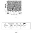
- Fig. 1 represents the visual acuity depending on the angular position around the fovea, which is cited from the page related to the "fovea centralis" of the Wikipedia.
- the fovea is the central area of the eye where the density of cones is the highest. This area represents only a couple of degrees, where the visual acuity is maximal. This acuity decreases rapidly when the field of view increases (see Fig. 1 ). It means that, even if a large field of view is required to bring a feeling of immersion to the viewer, the details cannot be perceived by the peripheral vision.
- the resolution of the display devices is based on this visual acuity characteristic: depending on the distance of observation, the pixels cannot be perceived if their spatial frequency is higher than the separation capability of the eye.
- the Human eye in the fovea area, can approximately discriminate two points separated by one minute of arc angle. It means for instance that a 42" HD (High Definition) screen 1920x1080 pixels, having a width of 93cm, can be watched at a distance of 166cm, to have a pixel density of 60 pixels per degree in its central part, corresponding approximately to the visual acuity.
- a 42" HD (High Definition) screen 1920x1080 pixels having a width of 93cm, can be watched at a distance of 166cm, to have a pixel density of 60 pixels per degree in its central part, corresponding approximately to the visual acuity.
- an example will be discussed in relation to an exemplary HMD device having a resolution of 1280x800 pixels.
- the horizontal field of view will be approximately 90° (or 110° depending on the sources), and the theoretical number of pixels per eye will be 640 (but likely closer to 500 practically): 500 pixels distributed over 90° implies a pixel density lower than 5 pixels per degree. That is 10 times lower than what should be required to respect Nyquist-Shannon sampling theorem for a visual acuity of one arc minute. Even if the next generation of this HMD should be based on a display having 1920x1080 pixels, the resolution should remain far below the visual acuity in the fovea area.
- the pixel density in the peripheral vision area is too high to be perceived by the human eye as visual acuity decreases strongly in the visual periphery.
- This disclosure illustratively describes a display device such as HMD device increasing the pixel density in an area of the display, and decreasing this density in the peripheral areas of the area with increased pixel density. Since the eyes can move in the content provided by the display, this increase of density is not limited to the extremely narrow area corresponding to the fovea, but is applied to an area corresponding to the average eye movements, before moving the head. It means that the user can move his gaze around an area with high density information, and enjoy a feeling of immersion thanks to the large field of view providing sparse information.
- the user can move his/her head to center of an object or area perceived with low resolution in periphery, to then dramatically increase the resolution on this object or area.
- IMU inertial measurement unit
- the pixels generated by the display device are distributed by the optics with an almost constant density over the whole field of view. Since this optics is simple, it introduces a strong pincushion distortion that must be compensated by signal processing, by applying the inverse deformation to the video content to be displayed. The viewer can perceive a video or graphic immersive content with a large field of view, but with a poor resolution, even in the central area of the HMD.
- Foveation is known in the technical field of image acquisition. Images can be acquired thanks to foveated sensors, where the density of photosites is higher in the central area of the sensor or with a standard sensor associated with a foveated lens. Foveated imaging is also known in the technical field of signal processing, covering image compression, image transmission, or gaze contingent displays. For this last application, an eye tracker detects where the user is looking, and more information (image portions containing high frequencies) is dynamically displayed in this area than in the periphery (only low frequencies, blur).
- the repartition of the pixels may be modified by the transformation T applied by the optics.
- the content to be displayed needs to be modified by the inverse geometric transformation T -1 .
- an increase of the pixel density increases the perceived luminance, and vice versa.
- This modification of luminance needs to be totally or partially compensated by the display or the signal processing applied to the images to be displayed.
- Fig. 2 presents the general overview according an embodiment of the present disclosure.
- a conventional optical element modifies the light as if it was generated at infinity (or at finite but large distance) from the viewer to allow accommodation by the viewer's eyes. It can also increase the field of view of the display to improve the feeling of immersion by the viewer.
- the non-limitative embodiment of the present disclosure proposes that the optical element applies a distortion (as shown in Fig. 3 ) to modify the perceived pixel density, depending on the distance to the center. This distance may be radial or axial, according to the horizontal axes.
- the distortion caused by the optical element of the embodiment of the present disclosure provides pixels repartition, that is, constant density of pixels displayed on the display is transformed into a modified pixels density in which increased pixels density is perceived in the central area of field of view.
- Fig. 4 illustrates a geometric transformation process applied to an image according to the embodiment of the present disclosure.
- the input image I is transformed by the function T -1 (I), preserving the details in the central area.
- This transformation must correspond to the inverse transformation function applied by the optical element of the embodiment of the present disclosure. It may be approximated for example by a polynomial function.
- the optical element applies the distortion T(I1), to provide the image I to the viewer, with a high density of information in the central area (around ⁇ ) which is the center of the field of view (see Fig. 4 ).
- the pixel density perceived by the viewer is represented by a curve in Fig. 4 .
- the " ⁇ " represents the position around ⁇ , defining the limit position where the pixel density is increased or decreased, compared to a constant density of pixels. This curve depends on the optical transformation and is given here as an example. The perceived density of pixels could for instance decrease continuously, up to the maximum field of view.
- the position ⁇ where the perceived density is at a maximum value is here placed at 1/2 FOV (Field of View).
- This position can vary if the eye moves and be tracked by an eye tracking system on the HMD device.
- the optical element can be shifted left to right, up and down depending on the output from the eye tracking system output signal to align the maximum density region with the optical axis of a given eye.
- the image signal will be modified according to the new T/T -1 transforms associated with the modified optical configuration.
- the value ⁇ can be decreased in the optical design, restricted to the fovea extension but excluding the eye motion margins considered in the static configuration.
- the proposed solution has to be compared to the standard implementation in order to compare the relative perceived pixel density per angular sector.
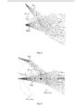
- Fig. 5 illustrates a design of a lens with the same functionality than in the original system.
- the optical system is dimensioned for having a total field of view of about 95°, the object field width is 2x37.5mm, which is the width of the screen.
- Fig. 5 shows the ray tracing for the axial field point, an intermediary one and the marginal field.
- the system is designed to be afocal in image space and the pupil is of 4mm at 10mm distance from the sag of the last optical surface.
- the MTF (Modulation Transfer Function) at the marginal field point is of course pretty bad as this can be inferred from the non-collimated red sub-beam reaching the pupil.
- the perceived field of view in image space is of ⁇ 29°.
- a lens In order to modify the perceived angular pixel densities, a lens needs to be set up in the vicinity of the object plane. That field lens shall map the pixels in the central part of the display around the optical axis with more angular density in the image space than outer pixels.
- the optical surface with such a property is necessarily an even asphere. It is a rotationally symmetric polynomial aspheric surface described by a polynomial expansion of the deviation from a spherical surface.
- the even asphere surface model uses only the even powers of the radial coordinate to describe the asphericity.
- c is the curvature
- r is the radial coordinate in lens units
- k is the conic constant.
- the field lens needs to have both its front surface aspheric in order to modulate separately the different locations of the field points, and it also needs to have a rear aspheric surface for pointing each chief ray toward the entrance pupil of the optical system of the HMD device of the present embodiment.
- Fig. 6 shows the whole optical system of the HMD device of the present embodiment, which improves the angular resolution density near the axis.
- the first lens is the one which is warping the field points to different angular densities in the image space. Its shape seems complicated but it is made out of B 270 (trademark) glass by SCHOTT AG and can be molded in high volumes and low costs as well as the main lens which is also made of the same material and which also needs to be molded since it also has two aspheric surfaces.
- the lens prescription is as follows: SURFACE DATA SUMMARY: Surf. Type Radius Thickness Glass Diameter Conic Comment OBJ STANDARD Infinity 4.3333 75 0 1 EVENASPH 41.44078 4.669471 BK7 61.37206 0 2 EVENASPH 6.699356 40.00001 57.869 2.287118 STO STANDARD Infinity 0 20 0 4 EVENASPH -22.21413 20 BK7 26.72005 0 5 EVENASPH -18.07581 Infinity 10 35.41718 0 IMA STANDARD 4 0 SURFACE DATA DETAIL: Surface OBJ STANDARD Surface 1 EVENASPH Coefficient on r ⁇ 2 : 0 Coefficient on r ⁇ 4 : -6.9859233e-005 Coefficient on r ⁇ 6 : 2.4668817e-007 Coefficient on r ⁇ 8 : -3.9883699e-010 Coefficient on r ⁇ 10 : 5.5885882e-013
- the MTF has been improved also.
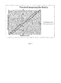
- the perceived field of view can be plotted as a function of the field position on the display as shown in Fig. 7 .
- the improved system has effectively a curve shaped like the theoretical one shown in Fig. 4 resulting in a higher perceived pixel density in the vicinity of the optical axis direction.
- Fig. 8 schematically illustrates a display device according to an embodiment of the present disclosure, in which Fig. 8(a) is a plan view of the device and Fig. 8(b) is a front view of the device.
- a display device 100 may include a display module 105 which can be an LCD (Liquid Crystal Display) with a light source or an OLED (Organic Light Emitting Display), for example.
- Fixing elements 110 such as temple arms, that will extend respectively over the ears of a viewer to help hold the device 100 in place, are mounted on both sides of the display device 100.
- the fixing element 110 may be an expansion band to hold the device 100 on viewer's head.
- the display device 100 also includes an optical component 120 and an actuator 115 to move the optical component 120.
- the optical component 120 may comprise the two optical elements designed as described above in connection with Fig. 6 .
- the optical component 120 is connected to the actuator 115 through a connecting member 125.
- the actuator 115 is mounted on the fixing elements 110 and the optical component 120 is supported by the connecting member 125 in front of the display module 105.
- These actuator 115, optical component 120 and connecting member 125 are mounted on both sides of the fixing elements 110, respectively. Thanks to the actuators 115, the optical components 120 can be moved up and down and left to right, as indicated by the arrows shown in Fig. 8(b) , respectively.
- each optical element of the optical component 120 can alternatively have a form of Fresnel lens so that the optical elements can have thinner shape and lighter weight.
- the display device 100 is provided with an eye tracking sensor 130 to detect eye gaze point of the eyes of viewer.
- the eye tracking sensor 130 may be mounted on the upper or lower portion of the display module 105, for example so as to prevent any shading of display screen which may be caused by the sensor 130.
- display device 100 is provided with a position sensor 145 such as inertial measurement unit (IMU) to measure the position of a viewer's head on which the display device 100 is mounted.
- IMU inertial measurement unit
- the display device 100 further includes a control module 140 to control the display module 105, actuators 115, the eye tracking sensor 130 and the position sensor 145.
- the control module 140 is connected to these elements via wired or wireless connection.
- the control module 140 is also connected to an external device (not shown) via wired or wireless connection.
- the external device stores images or videos to be provided to the display device 100. The images or videos are provided from the external device to the control module 140, then the control module 140 presents the received image or video on the display module 105.
- the display device 100 may have a hood (not shown) surrounding the periphery of the display module 105 to provide a dark space in the field of view of the viewer, which may provide the viewer with better feeling of immersion.
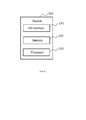
- Fig. 9 is a block diagram illustrating components of the control module shown in Fig. 8 .
- the control module 200 comprises an I/O interface 210 and a memory device 220.
- the interface 210 and memory device 220 are configured to receive and store images or videos to be presented on the display module 105 ( Fig. 8 ).
- the module 200 further comprises a processor 230.
- the processor 230 performs to detect eye gaze point of the viewer based on the inputs from the eye tracking sensor 130, to activate the actuators 115 in response to the detected eye gaze point, to present images or videos received from the external device on the display module 105 and to scroll the images or videos displayed on the display module 105 in response to a viewer's head position detected and input by the position sensor 145.
- the processor 230 further performs to modify the images or videos by applying a geometric transformation T -1 (I) as described in reference to Fig. 4 so that information density of the images or videos in an area around the detected eye gaze point on the display 105 ( Fig. 8 ) can be increased.
- the processor 230 may further apply luminance compensation to compensate a variation of luminance in the images or videos which could be caused by the geometric transformation T -1 (I).
- the memory device 220 is also configured to store at least one program to be executed by the processor 230 for performing the above mentioned processes.
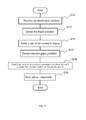
- Fig. 10 is a flow chart illustrating an example of a process performed by the display device according to an embodiment of the present disclosure.
- the control module 140; 200 of the display device 100 receives an immersive, image or video content from an external device (not shown) via its I/O interface 210.
- the received content is stored on the memory module 230.
- the immersive content may be a whole content available for the HMD device to display a 360° content (or less than 360°, but more than what can be displayed by the HMD's display screen), in other words, the immersive content may have wider area than the area of HMD's display screen. Thanks to such an immersive content, a viewer can be immersed in a virtual world displayed on the HMD device and can move his/her head to select a part of the whole 360° content he/she wants to see.
- step S12 the viewer's head position is detected by the position sensor 145, then at step S14, a part of the 360° content to be displayed on the HMD device is selected by the processor 220.
- the part of the 360° content that the viewer wants to see corresponds to the detected head position.
- step S16 eye gaze position of the eyes of viewer on which the display device 100 is mounted is determined by the eye tracking sensor 130.
- the detected information is output from the sensor 130 to the processor 220 of the control module 200.
- the processor 220 Based on the detected information, the processor 220 performs an analysis for specifying an eye gaze position of the eyes of viewer on the display module 105, in other words, for specifying which area on the display module 105 the viewer is watching. It should be noted that the step S16 can be performed during steps S10-S14.
- information of Region of Interest (ROI) in the content can be employed to determine eye gaze position of the eyes of viewer instead of the detection of eye gaze position by the eye tracking sensor 130.
- ROI Region of Interest
- areas of ROI in the content can be determined in advance by test users or by any known dedicated ROI analysis software and associated with the content via metadata incorporated in the content.
- the areas of ROI in the content can be presumed eye gaze positions since the viewer most likely pay attention to the area of ROI in the content and thus eye gaze will be even more attracted by these ROIs.
- the processor 220 reads out the image or video stored in the memory module 230 and modifies the image or video so that an area having higher density information of the image or video can be formed at the specified eye gaze position on the display 105.
- the modification of the image or video may be performed by applying a geometric transformation which corresponds to the inverse transformation function applied by the optical components 120 ( Fig. 4 ). Then, the processor 220 presents the modified image or video content on the display device 105.
- the processor 220 controls the actuators 115 to move the respective optical components 120 in response to the specified eye gaze position on the display 105 so that the viewer can see the display 105 through the optical components 120.
- the processor 220 causes the actuators 115 to move the optical components 120 to a position which corresponds to the detected eye gaze position according to the association.
- the optical components 120 apply the distortion T(I1) which will compensate the transformation made on the image or video presented on the display 105, the image or video content perceived by the viewer through the optical components 120 has a higher density of information in the eye gaze position than that in the periphery of the eye gaze position.
- the steps S12 through S20 may be repeated during the image or video content is presented on the display 105, which allows to change the dense information area on the image or video (the area of the image or video content having higher density of information than that in the rest of the content) and the positions of the optical components 120 in response to the detected eye gaze position in real time.
- the density of information available in the eye gaze area on the display 105 can be dramatically increased, thus more details can be provided in this area.
- the visual acuity is much lower in peripheral vision, the feeling of immersion brought by a large field of view can be preserved.
- the dense information area on the image or video and the positions of the optical components 120 may be fixed, for example, the dense information area on the image or video may be fixed in the central area of the image or video on the display 105 and positions of optical components 120 may be the corresponding positions. In this case, the above described steps S12 and S16 may be omitted.
- the processor 220 may modify the image or video directly received from the external device and present the modified image or video on the display device 105.
- the received image or video content may not be stored on the memory module 230.
Landscapes
- Engineering & Computer Science (AREA)
- Physics & Mathematics (AREA)
- General Physics & Mathematics (AREA)
- Theoretical Computer Science (AREA)
- Optics & Photonics (AREA)
- Human Computer Interaction (AREA)
- General Engineering & Computer Science (AREA)
- Multimedia (AREA)
- Health & Medical Sciences (AREA)
- Ophthalmology & Optometry (AREA)
- General Health & Medical Sciences (AREA)
- Computer Vision & Pattern Recognition (AREA)
- Data Mining & Analysis (AREA)
- Evolutionary Biology (AREA)
- Evolutionary Computation (AREA)
- Life Sciences & Earth Sciences (AREA)
- Signal Processing (AREA)
- Artificial Intelligence (AREA)
- Bioinformatics & Computational Biology (AREA)
- Bioinformatics & Cheminformatics (AREA)
- Control Of Indicators Other Than Cathode Ray Tubes (AREA)
- Image Processing (AREA)
- Devices For Indicating Variable Information By Combining Individual Elements (AREA)
Priority Applications (11)
| Application Number | Priority Date | Filing Date | Title |
|---|---|---|---|
| EP14305923.6A EP2958074A1 (fr) | 2014-06-17 | 2014-06-17 | Procédé et dispositif d'affichage avec optimisation de répartition de pixel |
| TW104115461A TWI660201B (zh) | 2014-06-17 | 2015-05-15 | 在顯示裝置上呈現影像之方法及呈現影像之顯示裝置 |
| PCT/EP2015/063435 WO2015193287A1 (fr) | 2014-06-17 | 2015-06-16 | Procédé et dispositif d'affichage avec optimisation de répartition de pixels |
| CN201580031912.8A CN106461951B (zh) | 2014-06-17 | 2015-06-16 | 利用像素再分配优化的方法和显示设备 |
| MX2016016718A MX371370B (es) | 2014-06-17 | 2015-06-16 | Un metodo y un dispositivo de visualizacion con optimizacion de reparticion de pixeles. |
| CA2952710A CA2952710C (fr) | 2014-06-17 | 2015-06-16 | Procede et dispositif d'affichage avec optimisation de repartition de pixels |
| JP2016573551A JP6684728B2 (ja) | 2014-06-17 | 2015-06-16 | 画素配分最適化を用いた方法およびディスプレイ装置 |
| RU2017101239A RU2693329C2 (ru) | 2014-06-17 | 2015-06-16 | Способ и устройство отображения с оптимизацией перераспределения пикселей |
| KR1020167035037A KR102503029B1 (ko) | 2014-06-17 | 2015-06-16 | 픽셀 재분할 최적화를 갖는 방법 및 디스플레이 디바이스 |
| US15/318,997 US11593914B2 (en) | 2014-06-17 | 2015-06-16 | Method and a display device with pixel repartition optimization |
| EP15728878.8A EP3158531B1 (fr) | 2014-06-17 | 2015-06-16 | Procédé et dispositif d'affichage avec optimisation de répartition de pixel |
Applications Claiming Priority (1)
| Application Number | Priority Date | Filing Date | Title |
|---|---|---|---|
| EP14305923.6A EP2958074A1 (fr) | 2014-06-17 | 2014-06-17 | Procédé et dispositif d'affichage avec optimisation de répartition de pixel |
Publications (1)
| Publication Number | Publication Date |
|---|---|
| EP2958074A1 true EP2958074A1 (fr) | 2015-12-23 |
Family
ID=51162628
Family Applications (2)
| Application Number | Title | Priority Date | Filing Date |
|---|---|---|---|
| EP14305923.6A Withdrawn EP2958074A1 (fr) | 2014-06-17 | 2014-06-17 | Procédé et dispositif d'affichage avec optimisation de répartition de pixel |
| EP15728878.8A Active EP3158531B1 (fr) | 2014-06-17 | 2015-06-16 | Procédé et dispositif d'affichage avec optimisation de répartition de pixel |
Family Applications After (1)
| Application Number | Title | Priority Date | Filing Date |
|---|---|---|---|
| EP15728878.8A Active EP3158531B1 (fr) | 2014-06-17 | 2015-06-16 | Procédé et dispositif d'affichage avec optimisation de répartition de pixel |
Country Status (10)
| Country | Link |
|---|---|
| US (1) | US11593914B2 (fr) |
| EP (2) | EP2958074A1 (fr) |
| JP (1) | JP6684728B2 (fr) |
| KR (1) | KR102503029B1 (fr) |
| CN (1) | CN106461951B (fr) |
| CA (1) | CA2952710C (fr) |
| MX (1) | MX371370B (fr) |
| RU (1) | RU2693329C2 (fr) |
| TW (1) | TWI660201B (fr) |
| WO (1) | WO2015193287A1 (fr) |
Families Citing this family (22)
| Publication number | Priority date | Publication date | Assignee | Title |
|---|---|---|---|---|
| EP3256900A4 (fr) * | 2015-02-12 | 2018-10-31 | Google LLC | Combinaison d'un affichage de champ étroit à haute résolution et d'un affichage de champ large à résolution moyenne |
| CN106293047B (zh) * | 2015-06-26 | 2020-01-10 | 微软技术许可有限责任公司 | 通过动态分辨率缩放来减少移动设备的功耗 |
| US10694102B2 (en) * | 2016-07-22 | 2020-06-23 | Immervision, Inc. | Method to capture, store, distribute, share, stream and display panoramic image or video |
| JP6844210B2 (ja) * | 2016-11-16 | 2021-03-17 | 凸版印刷株式会社 | 視覚的顕著性マップ生成装置、視覚的顕著性マップ生成方法及びプログラム |
| IL310618A (en) | 2017-03-22 | 2024-04-01 | Magic Leap Inc | A variable focus display system with a dynamic field of view |
| KR102270131B1 (ko) * | 2017-05-26 | 2021-06-28 | 구글 엘엘씨 | 스파스 샘플링 슈퍼-해상도를 가진 니어-아이 디스플레이 |
| JP6959365B2 (ja) * | 2017-06-09 | 2021-11-02 | 株式会社ソニー・インタラクティブエンタテインメント | 中心窩レンダリングシステムにおけるシャドーの最適化及びメッシュスキンの適応 |
| US20190079284A1 (en) * | 2017-09-08 | 2019-03-14 | Mediatek Inc. | Variable DPI Across A Display And Control Thereof |
| US10521881B1 (en) * | 2017-09-28 | 2019-12-31 | Apple Inc. | Error concealment for a head-mountable device |
| US10511842B2 (en) * | 2017-10-06 | 2019-12-17 | Qualcomm Incorporated | System and method for foveated compression of image frames in a system on a chip |
| JP7228584B2 (ja) | 2017-10-22 | 2023-02-24 | ラマス リミテッド | 光学ベンチを用いるヘッドマウント拡張現実デバイス |
| JP7325408B2 (ja) * | 2018-05-15 | 2023-08-14 | ソニーセミコンダクタソリューションズ株式会社 | 表示装置 |
| IL259518B2 (en) * | 2018-05-22 | 2023-04-01 | Lumus Ltd | Optical system and method for improving light field uniformity |
| KR20210100175A (ko) * | 2018-12-10 | 2021-08-13 | 페이스북 테크놀로지스, 엘엘씨 | 하이퍼보컬 뷰포트(hvp) 디스플레이를 위한 적응형 뷰포트 |
| CN118534643A (zh) | 2019-06-27 | 2024-08-23 | 鲁姆斯有限公司 | 基于经由光导光学元件对眼睛成像来进行眼睛追踪的设备和方法 |
| KR102582407B1 (ko) * | 2019-07-28 | 2023-09-26 | 구글 엘엘씨 | 포비에이티드 메시들로 몰입형 비디오 콘텐츠를 렌더링하기 위한 방법들, 시스템들, 및 매체들 |
| IL290719B2 (en) | 2019-12-08 | 2023-09-01 | Lumus Ltd | Optical systems with a compact image projector |
| WO2021130739A1 (fr) | 2019-12-25 | 2021-07-01 | Lumus Ltd. | Systèmes et procédés optiques d'oculométrie basée sur la réorientation de la lumière de l'œil au moyen d'un agencement optique associé à un élément optique guide de lumière |
| WO2021241073A1 (fr) * | 2020-05-27 | 2021-12-02 | ソニーグループ株式会社 | Dispositif et procédé d'affichage |
| US12039958B2 (en) | 2020-08-03 | 2024-07-16 | Arizona Board Of Regents On Behalf Of The University Of Arizona | Perceptual-driven foveated displays |
| TW202232186A (zh) | 2020-12-20 | 2022-08-16 | 以色列商魯姆斯有限公司 | 圖像投影儀 |
| US11899215B1 (en) * | 2022-07-29 | 2024-02-13 | Htc Corporation | Head mounted display, display device and image display method thereof |
Citations (3)
| Publication number | Priority date | Publication date | Assignee | Title |
|---|---|---|---|---|
| US20120154277A1 (en) | 2010-12-17 | 2012-06-21 | Avi Bar-Zeev | Optimized focal area for augmented reality displays |
| WO2013009414A2 (fr) * | 2011-07-12 | 2013-01-17 | Google Inc. | Système d'affichage à miroir de balayage d'image totale |
| US20140085190A1 (en) * | 2012-09-26 | 2014-03-27 | Dolby Laboratories Licensing Corporation | Display, Imaging System and Controller for Eyewear Display Device |
Family Cites Families (26)
| Publication number | Priority date | Publication date | Assignee | Title |
|---|---|---|---|---|
| JPH01252993A (ja) * | 1988-04-01 | 1989-10-09 | Nippon Telegr & Teleph Corp <Ntt> | 画像表示方法 |
| JPH0638219A (ja) | 1992-07-20 | 1994-02-10 | Olympus Optical Co Ltd | 映像表示装置 |
| JP2896291B2 (ja) * | 1993-06-14 | 1999-05-31 | 株式会社エイ・ティ・アール通信システム研究所 | 画像表示装置 |
| JP2638444B2 (ja) * | 1993-10-04 | 1997-08-06 | 日本電気株式会社 | 頭部搭載型画像表示装置 |
| JP3283367B2 (ja) * | 1993-11-11 | 2002-05-20 | 三菱プレシジョン株式会社 | 潜望鏡映像表示装置 |
| JP3604443B2 (ja) * | 1995-02-28 | 2004-12-22 | 株式会社島津製作所 | テレビジョンシステム |
| US6734838B1 (en) | 1998-05-18 | 2004-05-11 | Dimension Technologies Inc. | Enhanced resolution for image generation |
| JP2000310747A (ja) * | 1999-02-26 | 2000-11-07 | Mr System Kenkyusho:Kk | 画像観察装置 |
| US20020063807A1 (en) * | 1999-04-19 | 2002-05-30 | Neal Margulis | Method for Performing Image Transforms in a Digital Display System |
| JP4374708B2 (ja) * | 2000-03-30 | 2009-12-02 | 株式会社デンソー | 網膜走査ディスプレイ装置及び光走査装置 |
| WO2002067235A2 (fr) | 2001-02-21 | 2002-08-29 | Koninklijke Philips Electronics N.V. | Systeme d'affichage destine au traitement d'un signal video |
| US7068813B2 (en) | 2001-03-28 | 2006-06-27 | Koninklijke Philips Electronics N.V. | Method and apparatus for eye gazing smart display |
| US20060145945A1 (en) | 2002-01-07 | 2006-07-06 | Lewis John R | Scanned beam system with distortion compensation |
| US7495638B2 (en) * | 2003-05-13 | 2009-02-24 | Research Triangle Institute | Visual display with increased field of view |
| RU2322771C2 (ru) * | 2005-04-25 | 2008-04-20 | Святослав Иванович АРСЕНИЧ | Стереопроекционная система |
| JP2009510540A (ja) * | 2006-10-31 | 2009-03-12 | ビ−エイイ− システムズ パブリック リミテッド カンパニ− | 画像表示システム |
| US8314814B2 (en) * | 2007-12-20 | 2012-11-20 | Raytheon Company | Imaging system |
| US8941559B2 (en) | 2010-09-21 | 2015-01-27 | Microsoft Corporation | Opacity filter for display device |
| US9529191B2 (en) * | 2010-11-03 | 2016-12-27 | Trex Enterprises Corporation | Dynamic foveal vision display |
| WO2012172719A1 (fr) | 2011-06-16 | 2012-12-20 | パナソニック株式会社 | Afficheur facial et procédé de correction de défaut de centrage correspondant |
| US8749892B2 (en) * | 2011-06-17 | 2014-06-10 | DigitalOptics Corporation Europe Limited | Auto-focus actuator for field curvature correction of zoom lenses |
| US20130147686A1 (en) * | 2011-12-12 | 2013-06-13 | John Clavin | Connecting Head Mounted Displays To External Displays And Other Communication Networks |
| US20130215147A1 (en) | 2012-02-17 | 2013-08-22 | Esight Corp. | Apparatus and Method for Enhancing Human Visual Performance in a Head Worn Video System |
| US20130246967A1 (en) * | 2012-03-15 | 2013-09-19 | Google Inc. | Head-Tracked User Interaction with Graphical Interface |
| JP5935640B2 (ja) | 2012-10-01 | 2016-06-15 | ソニー株式会社 | 情報処理装置、表示制御方法及びプログラム |
| CN103593051B (zh) | 2013-11-11 | 2017-02-15 | 百度在线网络技术(北京)有限公司 | 头戴式显示设备 |
-
2014
- 2014-06-17 EP EP14305923.6A patent/EP2958074A1/fr not_active Withdrawn
-
2015
- 2015-05-15 TW TW104115461A patent/TWI660201B/zh active
- 2015-06-16 CN CN201580031912.8A patent/CN106461951B/zh active Active
- 2015-06-16 US US15/318,997 patent/US11593914B2/en active Active
- 2015-06-16 CA CA2952710A patent/CA2952710C/fr active Active
- 2015-06-16 EP EP15728878.8A patent/EP3158531B1/fr active Active
- 2015-06-16 RU RU2017101239A patent/RU2693329C2/ru active
- 2015-06-16 WO PCT/EP2015/063435 patent/WO2015193287A1/fr active Application Filing
- 2015-06-16 MX MX2016016718A patent/MX371370B/es active IP Right Grant
- 2015-06-16 KR KR1020167035037A patent/KR102503029B1/ko active IP Right Grant
- 2015-06-16 JP JP2016573551A patent/JP6684728B2/ja active Active
Patent Citations (3)
| Publication number | Priority date | Publication date | Assignee | Title |
|---|---|---|---|---|
| US20120154277A1 (en) | 2010-12-17 | 2012-06-21 | Avi Bar-Zeev | Optimized focal area for augmented reality displays |
| WO2013009414A2 (fr) * | 2011-07-12 | 2013-01-17 | Google Inc. | Système d'affichage à miroir de balayage d'image totale |
| US20140085190A1 (en) * | 2012-09-26 | 2014-03-27 | Dolby Laboratories Licensing Corporation | Display, Imaging System and Controller for Eyewear Display Device |
Non-Patent Citations (4)
| Title |
|---|
| EVRYDAYVR: "How barrel distortion works on the Oculus Rift", 19 January 2014 (2014-01-19), XP054975641, Retrieved from the Internet <URL:https://www.youtube.com/watch?v=B7qrgrrHry0> [retrieved on 20141209] * |
| HONG HUA ET AL: "A compact eyetracked optical see-through head-mounted display", PROCEEDINGS OF SPIE, S P I E - INTERNATIONAL SOCIETY FOR OPTICAL ENGINEERING, US, vol. 8288, 9 February 2012 (2012-02-09), pages 82881F - 1, XP008166319, ISSN: 0277-786X, DOI: 10.1117/12.909523 * |
| JOHANNES VOCKEROTH ET AL: "The combination of a mobile gaze-driven and a head-mounted camera in a Hybrid perspective setup", SYSTEMS, MAN AND CYBERNETICS, 2007. ISIC. IEEE INTERNATIONAL CONFERENC E ON, IEEE, PI, 1 October 2007 (2007-10-01), pages 2576 - 2581, XP031198834, ISBN: 978-1-4244-0990-7 * |
| OLIVER KREYLOS: "An Eye-tracked Oculus Rift | Doc-Ok.org", DOC-OK.ORG, 2 June 2014 (2014-06-02), pages 1 - 21, XP055157047, Retrieved from the Internet <URL:http://doc-ok.org/?p=1021> [retrieved on 20141205] * |
Also Published As
| Publication number | Publication date |
|---|---|
| CA2952710C (fr) | 2024-01-02 |
| TW201600887A (zh) | 2016-01-01 |
| CN106461951B (zh) | 2020-07-17 |
| MX371370B (es) | 2020-01-28 |
| KR102503029B1 (ko) | 2023-02-23 |
| JP2017522591A (ja) | 2017-08-10 |
| RU2017101239A (ru) | 2018-07-17 |
| KR20170020351A (ko) | 2017-02-22 |
| TWI660201B (zh) | 2019-05-21 |
| US20170132757A1 (en) | 2017-05-11 |
| EP3158531B1 (fr) | 2024-04-24 |
| WO2015193287A1 (fr) | 2015-12-23 |
| CN106461951A (zh) | 2017-02-22 |
| CA2952710A1 (fr) | 2015-12-23 |
| EP3158531A1 (fr) | 2017-04-26 |
| RU2693329C2 (ru) | 2019-07-02 |
| US11593914B2 (en) | 2023-02-28 |
| JP6684728B2 (ja) | 2020-04-22 |
| MX2016016718A (es) | 2017-04-13 |
| RU2017101239A3 (fr) | 2018-12-13 |
Similar Documents
| Publication | Publication Date | Title |
|---|---|---|
| EP3158531B1 (fr) | Procédé et dispositif d'affichage avec optimisation de répartition de pixel | |
| US11727695B2 (en) | Language element vision augmentation methods and devices | |
| US10984756B2 (en) | Adaptive parameters in image regions based on eye tracking information | |
| US9191658B2 (en) | Head-mounted display and position gap adjustment method | |
| US11816820B2 (en) | Gaze direction-based adaptive pre-filtering of video data | |
| US10284817B2 (en) | Device for and method of corneal imaging | |
| US9372348B2 (en) | Apparatus and method for a bioptic real time video system | |
| US11749024B2 (en) | Graphics processing method and related eye-tracking system | |
| WO2019217260A1 (fr) | Affichage fovéal dynamique | |
| US20230360571A1 (en) | Vision correction of screen images |
Legal Events
| Date | Code | Title | Description |
|---|---|---|---|
| PUAI | Public reference made under article 153(3) epc to a published international application that has entered the european phase |
Free format text: ORIGINAL CODE: 0009012 |
|
| AK | Designated contracting states |
Kind code of ref document: A1 Designated state(s): AL AT BE BG CH CY CZ DE DK EE ES FI FR GB GR HR HU IE IS IT LI LT LU LV MC MK MT NL NO PL PT RO RS SE SI SK SM TR |
|
| AX | Request for extension of the european patent |
Extension state: BA ME |
|
| STAA | Information on the status of an ep patent application or granted ep patent |
Free format text: STATUS: THE APPLICATION IS DEEMED TO BE WITHDRAWN |
|
| 18D | Application deemed to be withdrawn |
Effective date: 20160624 |