EP2956910B1 - Verfahren und vorrichtung zur anreicherung des inhalts einer tiefenkarte - Google Patents
Verfahren und vorrichtung zur anreicherung des inhalts einer tiefenkarte Download PDFInfo
- Publication number
- EP2956910B1 EP2956910B1 EP14703353.4A EP14703353A EP2956910B1 EP 2956910 B1 EP2956910 B1 EP 2956910B1 EP 14703353 A EP14703353 A EP 14703353A EP 2956910 B1 EP2956910 B1 EP 2956910B1
- Authority
- EP
- European Patent Office
- Prior art keywords
- depth
- information
- depth map
- scene
- fragment
- Prior art date
- Legal status (The legal status is an assumption and is not a legal conclusion. Google has not performed a legal analysis and makes no representation as to the accuracy of the status listed.)
- Active
Links
Images


Classifications
-
- G—PHYSICS
- G06—COMPUTING OR CALCULATING; COUNTING
- G06T—IMAGE DATA PROCESSING OR GENERATION, IN GENERAL
- G06T15/00—Three-dimensional [3D] image rendering
- G06T15/10—Geometric effects
-
- G—PHYSICS
- G06—COMPUTING OR CALCULATING; COUNTING
- G06T—IMAGE DATA PROCESSING OR GENERATION, IN GENERAL
- G06T1/00—General purpose image data processing
- G06T1/20—Processor architectures; Processor configuration, e.g. pipelining
-
- G—PHYSICS
- G06—COMPUTING OR CALCULATING; COUNTING
- G06T—IMAGE DATA PROCESSING OR GENERATION, IN GENERAL
- G06T15/00—Three-dimensional [3D] image rendering
- G06T15/50—Lighting effects
- G06T15/60—Shadow generation
-
- G—PHYSICS
- G06—COMPUTING OR CALCULATING; COUNTING
- G06T—IMAGE DATA PROCESSING OR GENERATION, IN GENERAL
- G06T17/00—Three-dimensional [3D] modelling for computer graphics
- G06T17/20—Finite element generation, e.g. wire-frame surface description, tesselation
-
- G—PHYSICS
- G06—COMPUTING OR CALCULATING; COUNTING
- G06T—IMAGE DATA PROCESSING OR GENERATION, IN GENERAL
- G06T7/00—Image analysis
- G06T7/50—Depth or shape recovery
- G06T7/529—Depth or shape recovery from texture
-
- G—PHYSICS
- G06—COMPUTING OR CALCULATING; COUNTING
- G06T—IMAGE DATA PROCESSING OR GENERATION, IN GENERAL
- G06T2215/00—Indexing scheme for image rendering
- G06T2215/12—Shadow map, environment map
Definitions
- the invention relates to the domain of depth map and more specifically to the enriching of the content of depth map(s).
- the invention is also understood in the context of Computer Generated Image (CGI or 3D-CGI).
- the finite resolution of the depth map leads to some approximations when determining if a first fragment of the scene is hidden by (or in the shadow of) a second fragment of the scene, the depth of which with regard to the camera field of view being stored in an element (also called pixel or texel) of the depth map.
- the resulting aliasing is known as bias aliasing. This aliasing may particularly occur when the first and second fragments belong to the same surface of an object of the scene as viewed from the camera field of view associated with the depth map.
- bias value that a fragment is considered occluded or in shadow when its distance to the camera field of view associated with the depth map is above the depth stored in an element of the depth map associated with this fragment plus the bias.
- introduction of a bias value may lead to another aliasing known as peter-panning artifact. David Tuft, "PLANE-BASED DEPTH BIAS FOR PERCENTAGE CLOSER FILTERING", gamedeveloper Vol. 17 No.
- the purpose of the invention is to establish depth information associated with one or more elements of a depth map with a better precision than in the state of the art.
- the invention will be described in reference to a particular embodiment of a method for enriching the content of a first element of a depth map.
- the depth map advantageously corresponds to an array of L lines and M columns of elements, L and M being integers greater than 0, and is associated with a scene which is rendered in one or more images.
- the number of elements comprised in the depth map corresponds for example to the number of pixels of the image(s) of the scene.
- the depth map is advantageously enriched with one or more first information representative of the variation of depth in the first element in the space of the depth map.
- the additional first information thus enables to retrieve, if needed, the depth associated with any point of the first element whereas, in depth map according to the prior art, the depth associated with any point of an element of a depth map is the same and corresponds to the depth of the closest visible fragment of the scene associated with the first element, or with its centre.
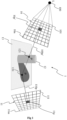
- Figure 1 shows a scene 1 rendered in an image 11 with an associated depth map 10, according to a particular and non-limitative embodiment.
- the image 11 represents the scene 1 as viewed from a given point of view (also called camera field of view, not represented on Figure 1 ) and the depth map is generated according to another point of view 100 (i.e. another camera field of view).
- the scene corresponds for example to a virtual scene and comprises several virtual objects, i.e. a first object 12 and a second object 13.
- the objects 12 and 13 are modelled according to any method known to those skilled in the art, for example by polygonal modelling, in which the model is assimilated with a set of polygons (mesh elements) each defined by the list of summits and edges that compose it, by NURBS (Non uniform rational basic spline) type curve modelling in which the model is defined by a set of curves created via control vertices, by modelling by subdivision of surfaces.
- polygonal modelling in which the model is assimilated with a set of polygons (mesh elements) each defined by the list of summits and edges that compose it
- NURBS Non uniform rational basic spline
- virtual object any virtual representation (obtained by modelling) of an object (real or fictitious) composing a real environment / real scene (for example the ground, a house or a house front, a person, a car, a tree, that is to say any element composing an environment such as a part of a house, a street, a town, the countryside, etc.) or an imaginary element.
- a real environment / real scene for example the ground, a house or a house front, a person, a car, a tree, that is to say any element composing an environment such as a part of a house, a street, a town, the countryside, etc.
- Each object 12, 13 of the scene 1 is characterized by a surface covering it, the surface of each object having reflectance properties (corresponding to the proportion of incident light reflected by the surface in one or several directions) that are specific to it.
- the depth map 10 comprises n elements 101 ... 10p' ... 10n, n being an integer greater than 0 that defines the resolution of the depth map 10, the resolution being for example equal to 512x512 pixels, 1024x1024 pixels or 4096x4096 pixels.
- a depth information is advantageously associated with each element of the depth map 10. This depth information corresponds to the distance between the point of view 100 and the closest visible fragment of the scene 1 along a viewing direction passing through an element of the depth map, this element of the depth map being associated with the closest visible fragment of the scene.
- the depth information associated with this element 10p' corresponds to the distance between the point of view 100 and the fragment P' 121 of the scene 1 along the viewing direction 100p' having as origin the point of view 100 and passing through the element 10p', advantageously passing through the centre of the element 10p'.
- the fragment P' 121 corresponds to the first element of the scene crossed by the viewing direction 100p' when starting from the point of view 100.
- the depth information is associated with the centre of the corresponding element of the depth map.
- a first information representative of the variation of depth inside an element of the depth map 10 is advantageously further associated with each element of the depth map, this first information being established as described with regard to figures 2 to 4 .
- the image 11 comprises m pixels 111 ... 11p ... 11m, m being an integer greater than 0 that defines the resolution of the image 11.
- m is different from n, for example n is greater than m or m is greater than n (the resolution of the depth map is for example 512x512 pixels, 1024x1024 pixels or 4096x4096 pixels whereas the resolution for the image 11 is for example 1024x768 pixels, 1280x720 pixels or 1920x1200 pixels).
- m is equal to n, both depth map 10 and image 11 having the same resolution.
- Attributes are advantageously associated with each pixel of the image 11, the attributes comprising for example color information (for example RGB information) and/or the translucent character of the fragment of the scene associated with a pixel of the image.
- a fragment advantageously corresponds to a surface element associated with a point of the scene 1, the size of which being equal to the size of a pixel of the image 11 that may be displayed to represent the scene 1 on a display screen.
- a fragment of the scene 1 becomes a pixel in the image if the fragment is visible from the point of view associated with the image 11.
- an element (for example a point) of the scene 1 will be called a fragment when positioning in the space of the 3D scene (the world space) and the same element visible from the point of view associated with the image 11 will be called pixel when positioning in the space of the image 11.
- a fragment visible from the point of view associated with the image 11 and the corresponding pixel in the image thus refers to one and a same element of the scene 1 and may be mixed up in the rest of the description.
- the fragment is defined by a set of data grouping together one or several of the following data items:
- the well-known z-buffer method (also known as z-buffer algorithm) is used in association with one or more depth maps having the same point of view as the image 11 and having a structure similar to the depth map 10.
- the one or more depth maps having the same point of view as the image 11 and being used in the z-buffer algorithm are also called z-buffer(s).
- the depths of the fragments of the scene located along the viewing direction 110p having as origin the point of view of the image 11 and passing through the centre of the pixel 11p are compared, and the fragment P 131 having the smallest depth (i.e.
- the shortest distance from the point of view along the viewing direction 110p) is the one whose attributes are associated with the pixel 11p.
- the well-known painter's algorithm is used for solving the visibility problem as to determine which fragment of the scene is visible for each pixel of the image 11 from the point of view of the image 11.
- the point of view 100 advantageously corresponds to the light source of the scene 1 and the depth map 10 is used to determine which fragment of the scene 1 is lit by the light source and which fragment of the scene is in shadow.
- the depth map 10 may also be called a shadow map. Then, as to determine whether the fragment P 131 (corresponding to the pixel 11p of the image 11) is lit or in the shadow of an object of the scene 1, the fragment P 131 is projected into the depth map along a viewing direction linking the point of view 100 and the fragment P 131.
- the distance ⁇ LP ⁇ between the point of view 100 and the fragment P 131 is compared to the depth information ⁇ LP' ⁇ associated with the centre of the element 10p' corresponding to the projection of the fragment P 131 into the depth map 10. If ⁇ LP ⁇ is greater than ⁇ LP' ⁇ , then the fragment P 131 is in the shadow of the fragment P' 121 (i.e. the fragment P 131 is not directly lit by the light source L). If ⁇ LP ⁇ is less than or equal to ⁇ LP' ⁇ , then the fragment P 131 is directly lit by the light source L. In an advantageous way, the depth information with which the distance ⁇ LP ⁇ is compared is retrieved from the depth information associated with the centre of the element 10p' and from the first information representing the variation of depth inside the element 10p'.
- the scene 1 is a real scene shot by a camera device generating the image 11 and advantageously one or more other images according to different points of view as to generate a stereoscopic image of the scene.
- a depth map is generated according to the same point of view as the image 11, the depth map and the image 11 being associated with each other.
- Depth maps associated with the other images of the scene may also be generated.
- the depth information associated with the centre(s) of the element(s) of the depth map is for example generated via a depth sensor associated with the camera.
- the depth map is generated by comparing two images of the scene 1 acquired according to two different points of view (for example a left image and a right image of the scene), a disparity information being retrieved by comparing on a pixel basis the two images for making a match between the pixels of each view by pairs of two, the disparity information corresponding to the difference in pixels according to the horizontal axis between the location of a pixel in the left image and the location of its corresponding pixel in the right image.
- the depth map according to this example is called a disparity map.
- the disparity map associated with the image 11 is representative of the disparity between image 11 (corresponding for example to a left image of a stereoscopic image) and another image of the stereoscopic image (for example the right image), another disparity map may be associated with the right image, this another disparity map being representative of the disparity between the right image and the left image 11.
- Each disparity map is advantageously estimated by comparison and pairing of the pixels of the left image 11 (respectively right image) to the pixels of the right image (respectively left image 11).
- the disparity associated with a pixel of the left image 11 advantageously corresponds to the pixel distance between this pixel of the left image 11 (respectively right image) and the corresponding (or paired) pixel of right image (respectively left image 11), that is to say, the pixel of the right image (respectively left image 11) having video information (that is to say, color information) identical or similar to that of the pixel of left image 11 (respectively right image).
- the first information representative of the variation of depth is established and associated with the elements of the depth map 10 (disparity map) as it will described with more details with regard to figures 2 to 4 .
- Figure 2 shows a part 20 of the depth map 10 of figure 1 , according to a particular and non-limitative embodiment.
- This part of the depth map is centred on a first element 21, which is surrounded by 8 elements of the depth map 10, among them the elements 22, 23 and 24, called second elements.
- a depth information p z,21 representative of the distance between the point of view 100 (not represented on Figure 2 ) and the fragment P T 25 is associated with the centre T 211 of the first element 21.
- the point T 211 of the first element corresponds to the projection point of the fragment P T 25 along the viewing direction 210 which passes through the first element 21.
- the point T' 212 which belongs to the first element 21, corresponds to the projection point of the fragment P T' 26 along the viewing direction 220 having as origin the point of view 100 associated with the depth map 10 and passing through the first element 21.
- the first fragment 25 and the second fragment are advantageously close to each other (for example adjacent) and belongs to the same surface of an object of the scene, i.e. the surface of the object 13 which is lit by the light source L (not represented on figure 2 ) corresponding to the point of view 100 associated with the depth map 10.
- the depth of the fragment P T' 26 according to the point of view 100 is compared with the depth information associated with the point T' 212, which is computed by using the depth information associated with the first element 21 (or with the centre T 211 of the first element 21) and the one or more first information representative of the variation of depth in the first element 21 that is (are) associated with the first element 21.
- the depth of the fragment P T' 24 would have only been compared with the depth information p z,21 associated with the centre T 211 of the first element 21, which may have led to visible artefacts.
- the surface of the object 13 to which the two fragments 25 and 26 belong is nearly tangent to the viewing directions 210 and 220 of the first and second fragments (or in another words, the angle formed by the surface normal of the object 13 and by one viewing direction 210 or 220 is high, i.e.
- a predetermined threshold angle for example greater than 45°
- both fragments P T 25 and P T' 26 are lit by the light source L (or visible from the point of view 100) as they belong to one and same surface of the object 13 and as their projection points T 211 and T' 212 in the depth map belong to the same first element 21.
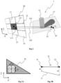
- Figures 3A and 3B show a first method to establish the one or more first information representative of the variation of depth in the first element 21, according to a particular and non-limitative embodiment of the present principles.
- Figure 3A illustrates a first surface element 30 which corresponds to the projection of a second surface element belonging to the scene 1, the second surface element corresponding for example to a mesh element (a polygon, for example a triangle) if the scene has been modelled by polygonal modelling or to a subdivision of a surface if the scene 1 has been modelled by subdivision of surfaces.
- the first surface element takes the form of a triangle and is defined in the space (x, y) of depth map 10.
- the first surface element 30 comprises at least 4 elements 21, 22, 23, 24 forming a 2x2 square of elements.
- the element 21 corresponds to the first element 21 of figure 2 , the elements 22, 23 and 24 being called second elements.
- dx represents the distance between the centre of the first element 21 and the centre of the second element 22 along the horizontal axis x, in the space (x, y) of the depth map.
- dy represents the distance between the centre of the first element 21 and the centre of the second element 23 along the vertical axis y, in the space (x, y) of the depth map.
- the first information representative of the variation of depth in the first element 21 in the space (x, y) of the depth map is advantageously established (i.e.
- the first information representative of the variation of depth in the first element along the x axis is established from the depth information associated with the centre of the first element 21 and from the depth information associated with the centre of the second element 22, which is advantageously adjacent to the first element 21 along the x axis, by taking into account the distance dx separating the centre of the first element 21 and the centre of the second element 22 along the x axis.
- Figure 3B illustrates the first element 21 and the second element 22 and the depth information d1 and d2 associated with their respective centres.
- d1 and d2 are represented with dashed arrows, the depth difference between the first element 21 and the second element 22 being represented with a line segment 31, the distance dx 32 between the centres of respectively the first element 21 and the second element 22 being represented by a double arrow.
- the first information representative of the variation of depth in the first element 21 corresponds to the slope of this line segment 31, which is obtained by establishing the partial derivative of the function of the straight line 31.
- the first information associated with the other elements 22, 23 and 24 is advantageously established with the same group of elements 21 to 24.
- the first information dp z , 22 dx representative of the variation of depth in the element 22 along the x axis is established from the depth information p(22) associated with the centre of the element 22 and from the depth information p(21) associated with the centre T 211 of the element 21, by taking into account the distance dx 32 separating the centre of the element 22 and the centre of the element 21.
- the first information dp z , 22 dy representative of the variation of depth in the element 22 along the y axis is established from the depth information p(22) associated with the centre of the element 22 and from the depth information p(24) associated with the centre of the element 24, by taking into account the distance dy separating the centre of the element 22 and the centre of the element 24.
- Figure 4 show a second method to establish the one or more first information representative of the variation of depth in the first element 21 of figure 2 , according to a particular and non-limitative embodiment.
- Figure 4 illustrates a first surface element 41 which corresponds to the projection of a second surface element 42 belonging to the scene 1, the second surface element corresponding for example to a mesh element (a polygon, for example a triangle) if the scene has been modelled by polygonal modelling or to a subdivision of a surface if the scene 1 has been modelled by subdivision of surfaces.
- the second surface element 42 is represented in the world space, i.e. the space of the scene 1.
- the first surface element 41 corresponds to the projection of the second surface element 42 in the tridimensional space 40 associated with an orthographic camera associated with the depth map 10.
- an orthographic camera enables to project the second surface element, which belong to the world space, into a tridimensional space (x, y, z) of the camera field of view associated with the depth map 10.
- Figure 5 diagrammatically illustrates the structure 5 of a memory element (or combination of memory elements) that represents the first element 21 of the depth map 10, according to a particular and non limitative embodiment of the present principles.
- the structure 5 comprises 3 memory blocks 50, 51, 52.
- the depth information p z,21 associated with the centre of the first element is stored in the first block 50
- the first information dp z,21 /dx representative of the variation of depth along the x axis of the space of the depth map is stored in the second block 51
- the first information dp z,21 /dy representative of the variation of depth along the y axis of the space of the depth map is stored in the third block 52.
- the structure of the depth map is for example a 32-bits RGBA buffer, 16 bits being used for the block 50, 8 bits for the second block 51 and 8 bits for the third block 52.
- the structure of the depth map is a 64-bits data array stored in a RGBA buffer with 32 bits for the first block 50 and 16 bits for each block 51 and 52. If only one first information is established (either along axis x or axis y), one of the block 51 and 52 is empty and the freed space memory may be used for storing the only one first information with more precision.
- the first information stored in the depth map 10 and associated with the first element 21 of figure 2 may then be used for computing the depth information associated with the point T' 212 of the first element 21.
- the distance ⁇ LP T' ⁇ between the point of view 100 and the fragment P T' 26 is compared with the depth information p z,T' associated with the point T' 212 and computed via the equation 9. If ⁇ LP T' ⁇ is less than or equal to p z,T' then the fragment P T' 26 is lit by the light source L 100 (not illustrated on figure 2 but illustrated on figure 1 ). If ⁇ LP T' ⁇ is greater than p z,T' then the fragment P T' 26 is not lit by the light source L 100.
- Figures 6A and 6B illustrate the encoding of the first information representative of the variation of depth in the first element 21 of the depth map 10, according to a particular and non-limitative embodiment.
- Values of the first information representative of the variation of depth in a first element of a depth map may be significantly small in presence of front facing surfaces (i.e. surfaces of object(s) having a normal parallel or roughly parallel with the viewing direction passing through the center of the first element 21 of the depth map) and conversely very large in presence of grazing angle surfaces (i.e. surfaces of object(s) of the scene having a normal perpendicular or roughly perpendicular to the normal of the depth map).
- Such amplitude requires high precision float storage and may significantly increase the depth map storage.
- angular functions are defined in the boundary range ⁇ ⁇ 2 , ⁇ 2 and may be stored in an unsigned 8 bits integer values for example, with a precision of ⁇ 256 , i.e approximately 0.703 degrees.).
- Figure 4A shows such a angular function 60, the range ⁇ ⁇ 2 , ⁇ 2 being normalized into [-1.0; 1.0].
- the first information values i.e. the derivative or rate
- the angular precision is not critical. Conversely it becomes critical near domain bounds, i.e. near ⁇ ⁇ 2 and ⁇ 2 .
- a small angular variation represent high derivative variation that may lead to erroneous depth reconstruction. Having higher precision may require an increasing data storage of 16 or 32 bits size for instance.
- the angular functions representative of the variation of depth in a first element of the depth map in the space of the depth map along axis x and y i.e.
- the functions ⁇ x (p z,21 ) and ⁇ y (p z,2 ,), are encoded in odd power functions x y (for example x 3 or x 5 ) in order to compress the angular domain around 0 and give higher precision for area near the domain bounds, i.e. near ⁇ ⁇ 2 and ⁇ 2 .
- Such function 61 and effective compression is showed in figure 6B with an odd power function ( figure 6B illustrating a normalized angular domain compression using odd power function (i.e. x 3 in the example of figure 6B )).
- Such an embodiment allows to record the first information (i.e. the derivatives) with a good precision with an only 8 bits data storage for each first information value.
- E dx (p z,21 ) and E dy (p z,21 ) (along the x axis and the y axis respectively) in an unsigned 8 bits integer are obtained as follow:
- E dx p z , 21 0.5 + 0.5 2 ⁇ ⁇ x p z , 21 ⁇ n ⁇ 255
- E dy p z , 21 0.5 + 0.5 2 ⁇ ⁇ y p z , 21 ⁇ n ⁇ 255 with n representing a positive odd integer.
- the decoding as to obtain the first information values is advantageously performed in scene rendering pass where depth comparison takes place as to determine whether a fragment is lit (or whether a fragment is visible).
- Figure 7 diagrammatically shows a hardware embodiment of a device 7 configured for enriching the content associated with a first element of a depth map.
- the device 7 is also configured for the creation of display signals of one or several synthesis images representative of the scene 1.
- the device 7 corresponds for example to a personal computer (PC), a laptop, a tablet, a Smartphone or a games console.
- the device 7 comprises the following elements, connected to each other by a bus 75 of addresses and data that also transports a clock signal:
- the device 7 also comprises a display device 73 of display screen type directly connected to the graphics card 72 to display synthesized images calculated and composed in the graphics card, for example live.
- a display device is external to the device 7 and is connected to the device 7 by a cable or wirelessly for transmitting the display signals.
- the device 7, for example the graphics card 72 comprises an interface for transmission or connection (not shown in figure 7 ) adapted to transmit a display signal to an external display means such as for example an LCD or plasma screen or a video-projector.
- register used in the description of memories 721, 76, and 77 designates in each of the memories mentioned, both a memory zone of low capacity (some binary data) as well as a memory zone of large capacity (enabling a whole program to be stored or all or part of the data representative of data calculated or to be displayed).
- the microprocessor 71 When switched-on, the microprocessor 71 loads and executes the instructions of the program contained in the RAM 77.
- the random access memory 77 notably comprises:
- the algorithms implementing the steps of the method specific to the invention and described hereafter are stored in the memory GRAM 721 of the graphics card 72 associated with the device 7 implementing these steps.
- the graphic processors 720 of the graphics card 72 load these parameters into the GRAM 721 and execute the instructions of these algorithms in the form of microprograms of "shader" type using HLSL (High Level Shader Language) language or GLSL (OpenGL Shading Language) for example.
- HLSL High Level Shader Language
- GLSL OpenGL Shading Language
- the random access memory GRAM 421 notably comprises:
- the first and second identifiers and the distances are stored in the RAM 77 and processed by the microprocessor 71.
- a part of the RAM 77 is assigned by the CPU 71 for storage of the identifiers and the distances if the memory storage space available in GRAM 721 is insufficient.
- This variant however causes greater latency time in the composition of an image comprising a representation of the environment composed from microprograms contained in the GPUs as the data must be transmitted from the graphics card to the random access memory 77 passing by the bus 75 for which the transmission capacities are generally inferior to those available in the graphics card for transmission of data from the GPUs to the GRAM and vice-versa.
- the power supply 78 is external to the device 7.
- Figure 8 shows a method for enriching the content associated with a first element of a depth map implemented for example in a device 7, according to a first non-restrictive particularly advantageous embodiment of the invention.
- the different parameters of the device 7 are updated.
- the parameters representative of the scene 1 represented in the image 11 as well as the depth information comprised in the depth map 10 are initialised in any way.
- a first information representative of the variation of the depth in a first element for example a texel or a pixel
- the first information is used for enriching the content of depth map of the state of the art which only comprises one depth information (called second information representative of the depth), associated with the centre of the first element, corresponding to the depth of the fragment of the scene that is visible from the point of view associated with the depth map along a viewing direction having as origin the point of view of the depth map and passing through the first element.
- two first information are established, i.e.
- first information representative of the variation of the depth along the horizontal axis of the space of the depth map and another first information representative of the variation of the depth along the vertical axis (which is perpendicular to the horizontal axis) of the space of the depth map.
- only one of the two first information is established, either the first information representative of the variation of the depth along the horizontal axis of the space of the depth map or the first information representative of the variation of the depth along the vertical axis of the space of the depth map.
- the first information is advantageously used in addition to the depth information associated with the centre of the centre of the first element to establish the depth information associated with any point of the first element, using the coordinates of this point expressed in the space of the depth map, instead of associated the depth information of the centre of the first element with any point of the first element as it is done according to the state of the art.
- the first information is for example established from the depth information associated with the centre of the first element and with the depth information associated with the centre of a second element of the depth map.
- the first and second elements belongs to a same surface element resulting from the projection of a surface element of the scene into the depth map.
- the first and second elements used to establish the first information representative of the variation of the depth along the horizontal axis of the space of the depth map are advantageously adjacent along the horizontal axis.
- the first and second elements used to establish the first information representative of the variation of the depth along the vertical axis of the space of the depth map are advantageously adjacent along the vertical axis.
- the first information advantageously corresponds to the ratio of the difference of depth between the first element and the second element to the distance between the first element and the second element (for example to the distance between the centre of the first element and the centre of the second element).
- the first information is established by using the equation of a surface element comprising the first element and obtained by projecting a surface element of the scene into the space of a camera field of view associated with the depth map.
- the first information corresponds to the slope(s) of this surface element, the equation of which being expressed in the space of the camera field of view of the depth map, with regard to the horizontal axis and/or vertical axis of the space of the depth map.
- the one or two first information is expressed under the form of a slope angle representing the variation of the depth in the first element.
- This (these) angular representation(s) of the first information is (are) encoded in odd power function.
- the first information is stored in a buffer associated with the depth map, in association with the first element.
- An image of the scene is rendered by displaying pixels associated with fragments of the scene which are visible from the point of view (i.e. the camera field of view) associated with the image.
- the color information e.g. RGB information
- the depth of a fragment associated with a pixel of the image is advantageously compared to the depth associated with the point of projection of the fragment into the depth map associated with the scene along a viewing direction having as origin the point of view of the depth map and as end the considered fragment, the depth associated with the point of projection being retrieved from the first information and the second information associated with the element of the depth map comprising the point of projection. This comparison enables to determine whether the considered fragment is lit (when the light source of the scene corresponds to the point of view of the depth map), which may have an impact on the color information associated with the fragment and thus on the color information associated with the pixel of the image to be rendered.
- the step 81 is advantageously reiterated for each element of the depth map and for each depth map associated with any image of the scene.
- the invention is not limited to a method for enriching the content of a depth map but also extends to any device implementing this method and notably any devices comprising at least one GPU.
- the implementation of calculations necessary to the generation of elementary geometries, to the determination of index values to be assigned to the elementary geometries is not limited either to an implementation in shader type microprograms but also extends to an implementation in any program type, for example programs that can be executed by a CPU type microprocessor.
- the use of the invention is not limited to a live utilisation but also extends to any other utilisation, for example for processing known as postproduction processing in a recording studio for the display of synthesis images for example.
- the invention also relates to a method (and a device configured) for encoding depth information representative of the variation of depth in an element of a depth map in the space of the depth map.
- the invention further relates to a method and device for determining the depth information associated with a point of a first element of depth map based on the depth information associated with the centre of the first element and on the additional depth information representative of the variation of the depth along the horizontal and/or vertical axis of the depth map.
- the implementations described herein may be implemented in, for example, a method or a process, an apparatus, a software program, a data stream, or a signal. Even if only discussed in the context of a single form of implementation (for example, discussed only as a method or a device), the implementation of features discussed may also be implemented in other forms (for example a program).
- An apparatus may be implemented in, for example, appropriate hardware, software, and firmware.
- the methods may be implemented in, for example, an apparatus such as, for example, a processor, which refers to processing devices in general, including, for example, a computer, a microprocessor, an integrated circuit, or a programmable logic device. Processors also include communication devices, such as, for example, Smartphones, tablets, computers, mobile phones, portable/personal digital assistants ("PDAs”), and other devices that facilitate communication of information between end-users.
- PDAs portable/personal digital assistants
- Implementations of the various processes and features described herein may be embodied in a variety of different equipment or applications, particularly, for example, equipment or applications associated with data encoding, data decoding, view generation, texture processing, and other processing of images and related texture information and/or depth information.
- equipment include an encoder, a decoder, a post-processor processing output from a decoder, a pre-processor providing input to an encoder, a video coder, a video decoder, a video codec, a web server, a set-top box, a laptop, a personal computer, a cell phone, a PDA, and other communication devices.
- the equipment may be mobile and even installed in a mobile vehicle.
- the methods may be implemented by instructions being performed by a processor, and such instructions (and/or data values produced by an implementation) may be stored on a processor-readable medium such as, for example, an integrated circuit, a software carrier or other storage device such as, for example, a hard disk, a compact diskette (“CD"), an optical disc (such as, for example, a DVD, often referred to as a digital versatile disc or a digital video disc), a random access memory (“RAM”), or a read-only memory (“ROM”).
- the instructions may form an application program tangibly embodied on a processor-readable medium. Instructions may be, for example, in hardware, firmware, software, or a combination.
- a processor may be characterized, therefore, as, for example, both a device configured to carry out a process and a device that includes a processor-readable medium (such as a storage device) having instructions for carrying out a process. Further, a processor-readable medium may store, in addition to or in lieu of instructions, data values produced by an implementation.
- implementations may produce a variety of signals formatted to carry information that may be, for example, stored or transmitted.
- the information may include, for example, instructions for performing a method, or data produced by one of the described implementations.
- a signal may be formatted to carry as data the rules for writing or reading the syntax of a described embodiment, or to carry as data the actual syntax-values written by a described embodiment.
- Such a signal may be formatted, for example, as an electromagnetic wave (for example, using a radio frequency portion of spectrum) or as a baseband signal.
- the formatting may include, for example, encoding a data stream and modulating a carrier with the encoded data stream.
- the information that the signal carries may be, for example, analog or digital information.
- the signal may be transmitted over a variety of different wired or wireless links, as is known.
- the signal may be stored on a processor-readable medium.
- the present invention may be used in video game applications for example, whether via programs that can be executed in a PC or portable type computer or in specialised game consoles producing and displaying images live.
- the device 7 described with respect to figure 7 is advantageously equipped with interaction means such as a keyboard a mouse, a joystick or any other modes for introduction of commands such as for example vocal recognition being also possible.
Landscapes
- Engineering & Computer Science (AREA)
- Physics & Mathematics (AREA)
- General Physics & Mathematics (AREA)
- Theoretical Computer Science (AREA)
- Computer Graphics (AREA)
- Geometry (AREA)
- Computer Vision & Pattern Recognition (AREA)
- Software Systems (AREA)
- Image Generation (AREA)
Claims (9)
- Computerimplementiertes Verfahren zum Erzeugen einer Tiefenkarte (10), die einer Szene (1) zugeordnet ist, in Übereinstimmung mit einem Blickpunkt (100), wobei jedem ersten Element (21) von mehreren ersten Elementen der Tiefenkarte (10) eine Tiefeninformation (50) zugeordnet wird,dadurch gekennzeichnet, dass das Verfahren in einem ersten Durchgangdas Speichern mindestens einer ersten Information (51, 52) in der Tiefenkarte (10) zusätzlich zu der Tiefeninformation (50) umfasst, wobei die mindestens eine erste Information (51, 52) dem jeden ersten Element (21) zugeordnet wird und eine Änderung der Tiefe in dem jeden ersten Element (21) in dem Raum der Tiefenkarte repräsentiert, wobei die mindestens eine erste Information gemäß der Form eines Steigungswinkels (60), der die Änderung der Tiefe in dem jeden ersten Element repräsentiert, ausgedrückt wird, wobei die mindestens eine erste Information in einer ungeraden Potenzfunktion (61) codiert wird undwobei das Verfahren ferner in einem zweiten Durchgang das Decodieren der in der Tiefenkarte (10) gespeicherten mindestens einen ersten Information,das Bestimmen, ob ein Bruchteil der Szene, der einem Pixel eines Bilds der Szene zugeordnet ist, von dem Blickpunkt der Tiefenkarte beleuchtet ist, durch Vergleichen einer Tiefe des betrachteten Bruchteils mit einer Tiefe, die einem Projektionspunkt des Bruchteils in die Tiefenkarte entlang einer Blickrichtung, die als Ursprung den Blickpunkt der Tiefenkarte und als Ende den betrachteten Bruchteil aufweist, zugeordnet ist, wobei die dem Projektionspunkt zugeordnete Tiefe aus der mindestens einen ersten Information, die dem ersten Element der Tiefenkarte, das den Projektionspunkt umfasst, zugeordnet ist, abgerufen wird, unddas Anzeigen von Pixeln, die den Bruchteilen, die beleuchtet sind, zugeordnet sind, umfasst.
- Verfahren nach Anspruch 1, wobei die mindestens eine erste Information (51, 52) aus der Tiefeninformation (50), die dem jeden ersten Element (21) zugeordnet ist, und aus der Tiefeninformation, die mindestens einem zweiten Element (22, 23) zugeordnet ist, hergestellt wird, wobei das jede erste Element und das mindestens eine zweite Element zu einem selben Oberflächenelement der in die Tiefenkarte projizierten Szene gehören.
- Verfahren nach Anspruch 2, wobei das jede erste Element (21) und das mindestens eine zweite Element (22, 23) benachbart sind.
- Verfahren nach einem der Ansprüche 2 bis 3, wobei die mindestens eine erste Information (51, 52) durch Berechnen des Verhältnisses der Differenz zwischen der Tiefeninformation, die dem jeden ersten Element (21) zugeordnet ist, und der Tiefeninformation, die dem mindestens einen zweiten Element (22) zugeordnet ist, zu dem Abstand (32) zwischen dem jeden ersten Element (21) und dem mindestens einen zweiten Element (22) hergestellt wird.
- Verfahren nach Anspruch 2, wobei die mindestens eine erste Information aus einer Gleichung des Oberflächenelements (41) der in den Raum eines Kamerablickfelds (40), dem die Tiefenkarte (10) zugeordnet ist, projizierten Szene hergestellt wird, wobei das projizierte Oberflächenelement (41) das jede erste Element umfasst.
- Verfahren nach einem der Ansprüche 2 bis 5, wobei das Oberflächenelement ein Maschennetzelement ist.
- Verfahren nach einem der Ansprüche 1 bis 6, wobei für jede Dimension des Raums der Tiefenkarte eine Information hergestellt wird.
- Vorrichtung (7) zum Erzeugen einer Tiefenkarte, die einer Szene (1) zugeordnet ist, in Übereinstimmung mit einem Blickpunkt (100), wobei jedem ersten Element (21) von mehreren ersten Elementen der Tiefenkarte (10) eine Tiefeninformation (50) zugeordnet wird, dadurch gekennzeichnet, dass die Vorrichtung mindestens einen Prozessor (720) umfasst, der in einem ersten Durchgang zum Speichern mindestens einer ersten Information (51, 52) in der Tiefenkarte (10) zusätzlich zu der Tiefeninformation (50) konfiguriert ist, wobei die mindestens eine erste Information (51, 52) dem jeden ersten Element (21) zugeordnet wird und eine Änderung der Tiefe in dem jeden ersten Element (21) in dem Raum der Tiefenkarte repräsentiert, wobei die mindestens eine erste Information gemäß der Form eines Steigungswinkels (60), der die Änderung der Tiefe in dem jeden ersten Element repräsentiert, ausgedrückt wird, wobei die mindestens eine erste Information in einer ungeraden Potenzfunktion (61) codiert wird und wobei der Prozessor ferner in einem zweiten Durchgang zum Decodieren der in der Tiefenkarte (10) gespeicherten mindestens einen ersten Information,Bestimmen, ob ein Bruchteil der Szene, der einem Pixel eines Bilds der Szene zugeordnet ist, von dem Blickpunkt der Tiefenkarte beleuchtet ist, durch Vergleichen einer Tiefe des betrachteten Bruchteils mit einer Tiefe, die einem Projektionspunkt des Bruchteils in die Tiefenkarte entlang einer Blickrichtung, die als Ursprung den Blickpunkt der Tiefenkarte und als Ende den betrachteten Bruchteil aufweist, zugeordnet ist, wobei die dem Projektionspunkt zugeordnete Tiefe aus der mindestens einen ersten Information, die dem ersten Element der Tiefenkarte, das den Projektionspunkt umfasst, zugeordnet ist, abgerufen wird, undAnzeigen von Pixeln, die den Bruchteilen, die beleuchtet sind, zugeordnet sind, konfiguriert ist.
- Vorrichtung nach Anspruch 8, wobei die mindestens eine erste Information aus der Tiefeninformation, die dem jeden ersten Element zugeordnet ist, und aus der Tiefeninformation, die mindestens einem zweiten Element zugeordnet ist, hergestellt wird, wobei das jede erste Element und das mindestens eine zweite Element zu einem selben Oberflächenelement der in die Tiefenkarte projizierten Szene gehören.
Priority Applications (1)
| Application Number | Priority Date | Filing Date | Title |
|---|---|---|---|
| EP14703353.4A EP2956910B1 (de) | 2013-02-12 | 2014-02-07 | Verfahren und vorrichtung zur anreicherung des inhalts einer tiefenkarte |
Applications Claiming Priority (4)
| Application Number | Priority Date | Filing Date | Title |
|---|---|---|---|
| EP13305164 | 2013-02-12 | ||
| EP13305792 | 2013-06-12 | ||
| EP14703353.4A EP2956910B1 (de) | 2013-02-12 | 2014-02-07 | Verfahren und vorrichtung zur anreicherung des inhalts einer tiefenkarte |
| PCT/EP2014/052396 WO2014124871A2 (en) | 2013-02-12 | 2014-02-07 | Method and device for enriching the content of a depth map |
Publications (2)
| Publication Number | Publication Date |
|---|---|
| EP2956910A2 EP2956910A2 (de) | 2015-12-23 |
| EP2956910B1 true EP2956910B1 (de) | 2025-03-05 |
Family
ID=50070560
Family Applications (1)
| Application Number | Title | Priority Date | Filing Date |
|---|---|---|---|
| EP14703353.4A Active EP2956910B1 (de) | 2013-02-12 | 2014-02-07 | Verfahren und vorrichtung zur anreicherung des inhalts einer tiefenkarte |
Country Status (6)
| Country | Link |
|---|---|
| US (1) | US10510179B2 (de) |
| EP (1) | EP2956910B1 (de) |
| JP (1) | JP2016510473A (de) |
| KR (1) | KR20150117662A (de) |
| CN (1) | CN104981849A (de) |
| WO (1) | WO2014124871A2 (de) |
Families Citing this family (11)
| Publication number | Priority date | Publication date | Assignee | Title |
|---|---|---|---|---|
| KR102223064B1 (ko) * | 2014-03-18 | 2021-03-04 | 삼성전자주식회사 | 영상 처리 장치 및 방법 |
| US10169909B2 (en) * | 2014-08-07 | 2019-01-01 | Pixar | Generating a volumetric projection for an object |
| EP3021286B1 (de) | 2014-11-13 | 2017-09-27 | Thomson Licensing | Vorrichtung und Verfahren zur Berechnung von Schatten in einer 3D-Szene |
| US10055883B2 (en) * | 2015-01-08 | 2018-08-21 | Nvidia Corporation | Frustum tests for sub-pixel shadows |
| US9412034B1 (en) * | 2015-01-29 | 2016-08-09 | Qualcomm Incorporated | Occlusion handling for computer vision |
| KR102299575B1 (ko) * | 2015-03-09 | 2021-09-07 | 삼성전자주식회사 | 위상 검출 픽셀들로부터 깊이 맵을 생성할 수 있는 이미지 신호 프로세서와 이를 포함하는 장치 |
| US10372968B2 (en) * | 2016-01-22 | 2019-08-06 | Qualcomm Incorporated | Object-focused active three-dimensional reconstruction |
| EP3249921A1 (de) * | 2016-05-24 | 2017-11-29 | Thomson Licensing | Verfahren, vorrichtung und stream für immersives videoformat |
| US20180032638A1 (en) * | 2016-07-27 | 2018-02-01 | Toyota Motor Engineering & Manufacturing North America, Inc. | Surface Analysis Systems and Methods of Generating a Comparator Surface Reference Model of a Multi-Part Assembly Using the Same |
| EP3467782A1 (de) * | 2017-10-06 | 2019-04-10 | Thomson Licensing | Verfahren und vorrichtung zum erzeugen von punkten einer 3d-szene |
| JP6487578B1 (ja) * | 2018-01-05 | 2019-03-20 | 株式会社スクウェア・エニックス | プログラム、記録媒体、及び影描画方法 |
Family Cites Families (8)
| Publication number | Priority date | Publication date | Assignee | Title |
|---|---|---|---|---|
| JPH075388A (ja) * | 1993-06-16 | 1995-01-10 | Fujitsu Ltd | 光走査装置 |
| US20060209065A1 (en) * | 2004-12-08 | 2006-09-21 | Xgi Technology Inc. (Cayman) | Method and apparatus for occlusion culling of graphic objects |
| WO2007096816A2 (en) * | 2006-02-27 | 2007-08-30 | Koninklijke Philips Electronics N.V. | Rendering an output image |
| US8269180B2 (en) * | 2008-08-27 | 2012-09-18 | Brookhaven Science Associates, Llc | Method and apparatus for the measurement of signals from radiation sensors |
| US8743114B2 (en) * | 2008-09-22 | 2014-06-03 | Intel Corporation | Methods and systems to determine conservative view cell occlusion |
| US8537200B2 (en) * | 2009-10-23 | 2013-09-17 | Qualcomm Incorporated | Depth map generation techniques for conversion of 2D video data to 3D video data |
| US9426444B2 (en) | 2011-06-24 | 2016-08-23 | Softkinetic Software | Depth measurement quality enhancement |
| CN102883175B (zh) * | 2012-10-23 | 2015-06-17 | 青岛海信信芯科技有限公司 | 深度图提取、判断视频场景切换及深度图边缘优化方法 |
-
2014
- 2014-02-07 JP JP2015557380A patent/JP2016510473A/ja not_active Withdrawn
- 2014-02-07 US US14/767,281 patent/US10510179B2/en active Active
- 2014-02-07 KR KR1020157021713A patent/KR20150117662A/ko not_active Withdrawn
- 2014-02-07 EP EP14703353.4A patent/EP2956910B1/de active Active
- 2014-02-07 CN CN201480008323.3A patent/CN104981849A/zh active Pending
- 2014-02-07 WO PCT/EP2014/052396 patent/WO2014124871A2/en not_active Ceased
Also Published As
| Publication number | Publication date |
|---|---|
| WO2014124871A2 (en) | 2014-08-21 |
| US10510179B2 (en) | 2019-12-17 |
| CN104981849A (zh) | 2015-10-14 |
| JP2016510473A (ja) | 2016-04-07 |
| WO2014124871A3 (en) | 2015-06-04 |
| US20160005213A1 (en) | 2016-01-07 |
| EP2956910A2 (de) | 2015-12-23 |
| KR20150117662A (ko) | 2015-10-20 |
Similar Documents
| Publication | Publication Date | Title |
|---|---|---|
| EP2956910B1 (de) | Verfahren und vorrichtung zur anreicherung des inhalts einer tiefenkarte | |
| EP3021286B1 (de) | Vorrichtung und Verfahren zur Berechnung von Schatten in einer 3D-Szene | |
| US10074211B2 (en) | Method and device for establishing the frontier between objects of a scene in a depth map | |
| EP2831848B1 (de) | Verfahren zur schätzung des opazitätsgrades in einer szene sowie entsprechende vorrichtung | |
| EP3246879A1 (de) | Verfahren und vorrichtung zur darstellung eines bildes einer szene mit einem realen objekt und einer virtuellen replika des realen objekts | |
| KR20160049031A (ko) | 타일 기반 렌더링에서의 테셀레이션 | |
| KR102442488B1 (ko) | 그래픽 처리 시스템 및 그래픽 프로세서 | |
| EP2676245B1 (de) | Verfahren zur schätzung von okklusion in einer virtuellen umgebung | |
| US20140354632A1 (en) | Method for multi-view mesh texturing and corresponding device | |
| US9607435B2 (en) | Method for rendering an image synthesis and corresponding device | |
| US9390551B2 (en) | Method for estimation of information representative of a pixel of a virtual object | |
| US20150006113A1 (en) | Method and device for estimating light scattering | |
| EP2801955A1 (de) | Verfahren und Vorrichtung zur Visualisierung von Kontakt(en) zwischen Objekten einer virtuellen Szene |
Legal Events
| Date | Code | Title | Description |
|---|---|---|---|
| PUAI | Public reference made under article 153(3) epc to a published international application that has entered the european phase |
Free format text: ORIGINAL CODE: 0009012 |
|
| 17P | Request for examination filed |
Effective date: 20150811 |
|
| AK | Designated contracting states |
Kind code of ref document: A2 Designated state(s): AL AT BE BG CH CY CZ DE DK EE ES FI FR GB GR HR HU IE IS IT LI LT LU LV MC MK MT NL NO PL PT RO RS SE SI SK SM TR |
|
| AX | Request for extension of the european patent |
Extension state: BA ME |
|
| DAX | Request for extension of the european patent (deleted) | ||
| STAA | Information on the status of an ep patent application or granted ep patent |
Free format text: STATUS: EXAMINATION IS IN PROGRESS |
|
| 17Q | First examination report despatched |
Effective date: 20180104 |
|
| RAP1 | Party data changed (applicant data changed or rights of an application transferred) |
Owner name: THOMSON LICENSING |
|
| P01 | Opt-out of the competence of the unified patent court (upc) registered |
Effective date: 20230529 |
|
| GRAP | Despatch of communication of intention to grant a patent |
Free format text: ORIGINAL CODE: EPIDOSNIGR1 |
|
| STAA | Information on the status of an ep patent application or granted ep patent |
Free format text: STATUS: GRANT OF PATENT IS INTENDED |
|
| INTG | Intention to grant announced |
Effective date: 20241030 |
|
| RIN1 | Information on inventor provided before grant (corrected) |
Inventor name: MARVIE, JEAN-EUDES Inventor name: GAUTRON, PASCAL Inventor name: LECOCQ, PASCAL |
|
| GRAS | Grant fee paid |
Free format text: ORIGINAL CODE: EPIDOSNIGR3 |
|
| GRAA | (expected) grant |
Free format text: ORIGINAL CODE: 0009210 |
|
| STAA | Information on the status of an ep patent application or granted ep patent |
Free format text: STATUS: THE PATENT HAS BEEN GRANTED |
|
| AK | Designated contracting states |
Kind code of ref document: B1 Designated state(s): AL AT BE BG CH CY CZ DE DK EE ES FI FR GB GR HR HU IE IS IT LI LT LU LV MC MK MT NL NO PL PT RO RS SE SI SK SM TR |
|
| REG | Reference to a national code |
Ref country code: GB Ref legal event code: FG4D |
|
| REG | Reference to a national code |
Ref country code: CH Ref legal event code: EP |
|
| REG | Reference to a national code |
Ref country code: IE Ref legal event code: FG4D |
|
| REG | Reference to a national code |
Ref country code: DE Ref legal event code: R096 Ref document number: 602014091634 Country of ref document: DE |
|
| PG25 | Lapsed in a contracting state [announced via postgrant information from national office to epo] |
Ref country code: RS Free format text: LAPSE BECAUSE OF FAILURE TO SUBMIT A TRANSLATION OF THE DESCRIPTION OR TO PAY THE FEE WITHIN THE PRESCRIBED TIME-LIMIT Effective date: 20250605 |
|
| PG25 | Lapsed in a contracting state [announced via postgrant information from national office to epo] |
Ref country code: FI Free format text: LAPSE BECAUSE OF FAILURE TO SUBMIT A TRANSLATION OF THE DESCRIPTION OR TO PAY THE FEE WITHIN THE PRESCRIBED TIME-LIMIT Effective date: 20250305 |
|
| REG | Reference to a national code |
Ref country code: NL Ref legal event code: MP Effective date: 20250305 |
|
| PG25 | Lapsed in a contracting state [announced via postgrant information from national office to epo] |
Ref country code: ES Free format text: LAPSE BECAUSE OF FAILURE TO SUBMIT A TRANSLATION OF THE DESCRIPTION OR TO PAY THE FEE WITHIN THE PRESCRIBED TIME-LIMIT Effective date: 20250305 |
|
| REG | Reference to a national code |
Ref country code: LT Ref legal event code: MG9D |
|
| PG25 | Lapsed in a contracting state [announced via postgrant information from national office to epo] |
Ref country code: NO Free format text: LAPSE BECAUSE OF FAILURE TO SUBMIT A TRANSLATION OF THE DESCRIPTION OR TO PAY THE FEE WITHIN THE PRESCRIBED TIME-LIMIT Effective date: 20250605 |
|
| PG25 | Lapsed in a contracting state [announced via postgrant information from national office to epo] |
Ref country code: HR Free format text: LAPSE BECAUSE OF FAILURE TO SUBMIT A TRANSLATION OF THE DESCRIPTION OR TO PAY THE FEE WITHIN THE PRESCRIBED TIME-LIMIT Effective date: 20250305 |
|
| PG25 | Lapsed in a contracting state [announced via postgrant information from national office to epo] |
Ref country code: LV Free format text: LAPSE BECAUSE OF FAILURE TO SUBMIT A TRANSLATION OF THE DESCRIPTION OR TO PAY THE FEE WITHIN THE PRESCRIBED TIME-LIMIT Effective date: 20250305 |
|
| PG25 | Lapsed in a contracting state [announced via postgrant information from national office to epo] |
Ref country code: BG Free format text: LAPSE BECAUSE OF FAILURE TO SUBMIT A TRANSLATION OF THE DESCRIPTION OR TO PAY THE FEE WITHIN THE PRESCRIBED TIME-LIMIT Effective date: 20250305 Ref country code: GR Free format text: LAPSE BECAUSE OF FAILURE TO SUBMIT A TRANSLATION OF THE DESCRIPTION OR TO PAY THE FEE WITHIN THE PRESCRIBED TIME-LIMIT Effective date: 20250606 |
|
| REG | Reference to a national code |
Ref country code: AT Ref legal event code: MK05 Ref document number: 1773652 Country of ref document: AT Kind code of ref document: T Effective date: 20250305 |
|
| PG25 | Lapsed in a contracting state [announced via postgrant information from national office to epo] |
Ref country code: NL Free format text: LAPSE BECAUSE OF FAILURE TO SUBMIT A TRANSLATION OF THE DESCRIPTION OR TO PAY THE FEE WITHIN THE PRESCRIBED TIME-LIMIT Effective date: 20250305 |
|
| PG25 | Lapsed in a contracting state [announced via postgrant information from national office to epo] |
Ref country code: SM Free format text: LAPSE BECAUSE OF FAILURE TO SUBMIT A TRANSLATION OF THE DESCRIPTION OR TO PAY THE FEE WITHIN THE PRESCRIBED TIME-LIMIT Effective date: 20250305 |
|
| PG25 | Lapsed in a contracting state [announced via postgrant information from national office to epo] |
Ref country code: PT Free format text: LAPSE BECAUSE OF FAILURE TO SUBMIT A TRANSLATION OF THE DESCRIPTION OR TO PAY THE FEE WITHIN THE PRESCRIBED TIME-LIMIT Effective date: 20250707 |
|
| PG25 | Lapsed in a contracting state [announced via postgrant information from national office to epo] |
Ref country code: PL Free format text: LAPSE BECAUSE OF FAILURE TO SUBMIT A TRANSLATION OF THE DESCRIPTION OR TO PAY THE FEE WITHIN THE PRESCRIBED TIME-LIMIT Effective date: 20250305 Ref country code: IT Free format text: LAPSE BECAUSE OF FAILURE TO SUBMIT A TRANSLATION OF THE DESCRIPTION OR TO PAY THE FEE WITHIN THE PRESCRIBED TIME-LIMIT Effective date: 20250305 |
|
| PG25 | Lapsed in a contracting state [announced via postgrant information from national office to epo] |
Ref country code: AT Free format text: LAPSE BECAUSE OF FAILURE TO SUBMIT A TRANSLATION OF THE DESCRIPTION OR TO PAY THE FEE WITHIN THE PRESCRIBED TIME-LIMIT Effective date: 20250305 |
|
| PG25 | Lapsed in a contracting state [announced via postgrant information from national office to epo] |
Ref country code: EE Free format text: LAPSE BECAUSE OF FAILURE TO SUBMIT A TRANSLATION OF THE DESCRIPTION OR TO PAY THE FEE WITHIN THE PRESCRIBED TIME-LIMIT Effective date: 20250305 Ref country code: CZ Free format text: LAPSE BECAUSE OF FAILURE TO SUBMIT A TRANSLATION OF THE DESCRIPTION OR TO PAY THE FEE WITHIN THE PRESCRIBED TIME-LIMIT Effective date: 20250305 |
|
| PG25 | Lapsed in a contracting state [announced via postgrant information from national office to epo] |
Ref country code: RO Free format text: LAPSE BECAUSE OF FAILURE TO SUBMIT A TRANSLATION OF THE DESCRIPTION OR TO PAY THE FEE WITHIN THE PRESCRIBED TIME-LIMIT Effective date: 20250305 |
|
| PG25 | Lapsed in a contracting state [announced via postgrant information from national office to epo] |
Ref country code: SK Free format text: LAPSE BECAUSE OF FAILURE TO SUBMIT A TRANSLATION OF THE DESCRIPTION OR TO PAY THE FEE WITHIN THE PRESCRIBED TIME-LIMIT Effective date: 20250305 |
|
| PG25 | Lapsed in a contracting state [announced via postgrant information from national office to epo] |
Ref country code: IS Free format text: LAPSE BECAUSE OF FAILURE TO SUBMIT A TRANSLATION OF THE DESCRIPTION OR TO PAY THE FEE WITHIN THE PRESCRIBED TIME-LIMIT Effective date: 20250705 |
|
| REG | Reference to a national code |
Ref country code: DE Ref legal event code: R097 Ref document number: 602014091634 Country of ref document: DE |
|
| PLBE | No opposition filed within time limit |
Free format text: ORIGINAL CODE: 0009261 |
|
| STAA | Information on the status of an ep patent application or granted ep patent |
Free format text: STATUS: NO OPPOSITION FILED WITHIN TIME LIMIT |
|
| PG25 | Lapsed in a contracting state [announced via postgrant information from national office to epo] |
Ref country code: DK Free format text: LAPSE BECAUSE OF FAILURE TO SUBMIT A TRANSLATION OF THE DESCRIPTION OR TO PAY THE FEE WITHIN THE PRESCRIBED TIME-LIMIT Effective date: 20250305 |
|
| REG | Reference to a national code |
Ref country code: CH Ref legal event code: L10 Free format text: ST27 STATUS EVENT CODE: U-0-0-L10-L00 (AS PROVIDED BY THE NATIONAL OFFICE) Effective date: 20260114 |
|
| 26N | No opposition filed |
Effective date: 20251208 |
|
| PGFP | Annual fee paid to national office [announced via postgrant information from national office to epo] |
Ref country code: GB Payment date: 20260219 Year of fee payment: 13 |
|
| PGFP | Annual fee paid to national office [announced via postgrant information from national office to epo] |
Ref country code: DE Payment date: 20260206 Year of fee payment: 13 |
|
| PGFP | Annual fee paid to national office [announced via postgrant information from national office to epo] |
Ref country code: FR Payment date: 20260227 Year of fee payment: 13 |